EP1684520A2 - Methode und Apparat für die Bildkompression - Google Patents
Methode und Apparat für die Bildkompression Download PDFInfo
- Publication number
- EP1684520A2 EP1684520A2 EP20050019462 EP05019462A EP1684520A2 EP 1684520 A2 EP1684520 A2 EP 1684520A2 EP 20050019462 EP20050019462 EP 20050019462 EP 05019462 A EP05019462 A EP 05019462A EP 1684520 A2 EP1684520 A2 EP 1684520A2
- Authority
- EP
- European Patent Office
- Prior art keywords
- image
- section
- processing
- value
- pixel
- Prior art date
- Legal status (The legal status is an assumption and is not a legal conclusion. Google has not performed a legal analysis and makes no representation as to the accuracy of the status listed.)
- Withdrawn
Links
Images


Classifications
-
- H—ELECTRICITY
- H04—ELECTRIC COMMUNICATION TECHNIQUE
- H04N—PICTORIAL COMMUNICATION, e.g. TELEVISION
- H04N19/00—Methods or arrangements for coding, decoding, compressing or decompressing digital video signals
- H04N19/80—Details of filtering operations specially adapted for video compression, e.g. for pixel interpolation
-
- G—PHYSICS
- G06—COMPUTING; CALCULATING OR COUNTING
- G06V—IMAGE OR VIDEO RECOGNITION OR UNDERSTANDING
- G06V40/00—Recognition of biometric, human-related or animal-related patterns in image or video data
- G06V40/10—Human or animal bodies, e.g. vehicle occupants or pedestrians; Body parts, e.g. hands
- G06V40/16—Human faces, e.g. facial parts, sketches or expressions
- G06V40/161—Detection; Localisation; Normalisation
- G06V40/162—Detection; Localisation; Normalisation using pixel segmentation or colour matching
-
- H—ELECTRICITY
- H04—ELECTRIC COMMUNICATION TECHNIQUE
- H04N—PICTORIAL COMMUNICATION, e.g. TELEVISION
- H04N1/00—Scanning, transmission or reproduction of documents or the like, e.g. facsimile transmission; Details thereof
- H04N1/40—Picture signal circuits
- H04N1/40062—Discrimination between different image types, e.g. two-tone, continuous tone
-
- H—ELECTRICITY
- H04—ELECTRIC COMMUNICATION TECHNIQUE
- H04N—PICTORIAL COMMUNICATION, e.g. TELEVISION
- H04N19/00—Methods or arrangements for coding, decoding, compressing or decompressing digital video signals
- H04N19/85—Methods or arrangements for coding, decoding, compressing or decompressing digital video signals using pre-processing or post-processing specially adapted for video compression
Definitions
- the present invention relates to an image compression method and an image compression device which compress an image having characteristics which are recognition objects in a character recognition device, a face collation device or the like.
- a time is preferably short for transmitting an image of the mail retaining a resolution required for character recognition.
- a face collation device an image including a collated face image is stored as a log in many cases.
- a time is preferably short for extracting the image stored as the log.
- Jpn. Pat. Appln. KOKAI Publication No. 9-116765 an image coding method is disclosed in which a difference value between adjacent pixels is calculated, and a variable-length code is allocated depending on an appearance frequency in coding of static image data by a reversible system.
- Jpn. Pat. Appln. KOKAI Publication No. 2000-156861 a method of compressing multi-valued information is disclosed in which there are calculated positive or negative binary information of a difference value between pieces of luminance information of the adjacent pixels and an absolute value, and a bitmap is developed every pixel to perform the coding.
- an object is to provide an image compression method and an image compression device capable of raising a compression efficiency of an image while maintaining characteristics as recognition objects in the image.
- a method of compressing an image comprising: performing image input processing to input the image having characteristics which are recognition objects; performing conversion processing to convert a pixel value of each pixel forming the image while retaining the characteristics which are the recognition objects in the image input by the image input processing; and performing coding processing with respect to the image converted by the conversion processing.
- an image compression device comprising: an image input section which inputs an image having characteristics which are recognition objects; a conversion processing section which converts a pixel value of each pixel forming the image while retaining the characteristics which are the recognition objects in the image input by the image input section; and a coding processing section which performs coding processing with respect to the image converted by the conversion processing section.
- FIG. 1 schematically shows a constitution example of an image compression device 100 according to a first embodiment.
- the image compression device 100 comprises an image input section 101, a smoothing processing section 102, a coding section 103, a data output section 104 and the like.
- the image input section 101 comprises, for example, a digital camera, a television camera, an image scanner or the like.
- the image input section 101 may input a color image or a monochromatic image.
- the image input section 101 inputs an image including a recognition object.
- the image input section 101 supplies the input image to the smoothing processing section 102.
- the image input section 101 inputs digital image data in which a value (pixel value) of each pixel is represented by a digital value.
- the image input section 101 inputs as the image the digital image data constituted of 640 pixels in a lateral direction (x-direction) and 480 pixels in a longitudinal direction (y-direction).
- the image input section 101 inputs the image data in which the pixel value of each pixel is represented by a luminance value.
- the image input section 101 may input the image data in which the value (pixel value) of each pixel is represented by a density value.
- the smoothing processing section 102 performs smoothing processing with respect to the image.
- the smoothing processing section 102 performs the smoothing processing as conversion processing with respect to the image supplied from the image input section 101. That is, the smoothing processing section 102 functions as a conversion processing section which performs the conversion processing with respect to the image input as an object of compression processing by the image input section 101.
- the smoothing processing section 102 supplies the smoothed image to the coding section 103.
- the smoothing processing section 102 has a function of performing filtering processing as the smoothing processing with respect to the image by a median filter. That is, the smoothing processing section 102 has a function of subjecting the image supplied from the image input section 101 to the filtering processing as the smoothing processing by the median filter.
- the coding section 103 performs variable-length coding processing as the compression processing with respect to the image.
- the coding section 103 subjects the image smoothed by the smoothing processing section 102 to the coding processing.
- the coding section 103 supplies the coded image to the data output section 104.
- the coding section 103 performs the coding processing (Huffman coding processing), for example, based on Huffman coding theory.
- the coding section 103 calculates an appearance frequency for each pixel value of each pixel forming the image (image data) smoothed by the smoothing processing section 102.
- the coding section 103 allocates a code having a less bit number to the pixel value having a higher appearance frequency. Accordingly, in the coding section 103, it is possible to allocate a Huffman code to the pixel value of each pixel in the image data.
- the coding section 103 performs variable-length coding processing with respect to the image (image data) supplied from the smoothing processing section 102 based on the Huffman coding theory.
- the coding section 103 does not necessarily have to use the Huffman coding processing as the coding processing.
- the coding section 103 may use run length coding processing or the like as the coding processing.
- the data output section 104 outputs as a compressed image the coded image supplied from the coding section 103.
- the data output section 104 outputs the compressed image to a recording device (not shown).
- FIGS. 2 and 3 are explanatory views of the smoothing processing in the smoothing processing section 102.
- FIG. 2 is an explanatory view of the filtering processing by the median filter with respect to an image constituted of 3x3 pixels (three pixels in an x-direction, three pixels in a y-direction).
- An image 121 shown in FIG. 2 shows an example of an image which is a processing object.
- each pixel of the image 121 is represented by a luminance value.
- An image 123 shown in FIG. 2 shows an image obtained by subjecting the image 122 to the filtering processing by the median filter.
- the luminance values as the pixel values of the respective pixels of the image 122 are (256, 256, 256, 0, 0, 0, 0, 0, 0). Therefore, an intermediate value calculated by the median filter is "0". Therefore, in the filtering processing by the median filter with respect to the image 122, the image 123 is obtained in which the luminance value of a central pixel is converted into the intermediate value ("0").
- FIG. 3 is an explanatory view of the smoothing processing by the smoothing processing section 102.
- An image 131 shown in FIG. 3 shows an example of the image which is the processing object similar to the image 121 shown in FIG. 2.
- each pixel of the image 131 is represented by a luminance value in the same manner as in the image 122 shown in FIG. 2.
- An image 133 shown in FIG. 3 shows an image as a processing result by the smoothing processing section 102 with respect to the image 132.
- the luminance value ("256") of the central pixel in the image 133 remains as that ("256") of the central pixel of the image 132.
- the luminance value ("256") of the central pixel is converted into the intermediate value ("0") as in the image 123 shown in FIG. 2.
- the smoothing processing is performed depending on a magnitude (difference value) of a difference between the intermediate value in the median filter and the luminance value of a noted pixel. That is, when the difference value between the intermediate value and the luminance value of the noted pixel is not less than a preset threshold value, the smoothing processing section 102 leaves the luminance value of the noted pixel after smoothed as that of the noted pixel before smoothed. When the difference value between the intermediate value and the luminance value of the noted pixel is less than a predetermined threshold value, the luminance value of the noted pixel after smoothed is converted into the intermediate value.
- the smoothing processing section 102 replaces the luminance value of the noted pixel after smoothed with the intermediate value in a case where the magnitude of the difference between the intermediate value and the luminance value of the noted pixel is less than the predetermined threshold value.
- the smoothing processing section 102 leaves the luminance value of the noted pixel after smoothed as that of the noted pixel before smoothed in a case where the magnitude of the difference between the intermediate value and the luminance value of the noted pixel is not less than the preset threshold value.
- Equation 1 represents the smoothing processing of the smoothing processing section 102 depending on the magnitude of the difference between the intermediate value and the luminance value of the noted pixel: ( Equation 1 )
- ⁇ Th , f ( x , y ) f ( x , y ) ; and
- ⁇ Th , f ( x , y ) Median ( f ( x + i , y + i ) ) , wherein f(x,y) denotes the luminance value of the noted pixel before smoothed, Median (f(x+i, y+i)) denotes the intermediaire value, and Th denotes the thresold
- FIG. 4 is a flowchart showing a flow of the smoothing processing in the smoothing processing section 102.
- each pixel in the image is successively regarded as the noted pixel, and the median filter is applied to the pixel.
- the smoothing processing section 102 calculates the intermediate value in the median filter (step S1). For example, when the smoothing processing section 102 has the median filter with respect to 3x3 pixels, the section calculates the intermediate value with respect to the image constituted of 3x3 pixels.
- the smoothing processing section 102 calculates the magnitude (difference value) of the difference between the intermediate value and the luminance value of the noted pixel. On calculating the difference value between the intermediate value and the luminance value of the noted pixel, the smoothing processing section 102 judges whether or not the calculated difference value is not less than the preset threshold value (step S2).
- step S2 the smoothing processing section 102 leaves the luminance value of the noted pixel after smoothed as that of the noted pixel before smoothed.
- the smoothing processing section 102 replaces the luminance value of the noted pixel after smoothed with the intermediate value (step S3).
- the smoothing processing section 102 regards as the noted pixels all of the pixels in the image supplied from the image input section 101 to perform the above-described processing. That is, the smoothing processing section 102 repeatedly executes the processing of the steps S1 to S3 to thereby regard all of the pixels in the image as the noted pixels and perform the smoothing processing. Accordingly, the smoothing processing section 102 subjects the whole image supplied from the image input section 101 to the smoothing processing.
- the smoothing processing section 102 can perform the smoothing processing suitable for the compression while retaining the characteristics which are the recognition objects with respect to the image of the compression object.
- the image of the compression object is subjected to such smoothing processing as to leave the luminance value of the noted pixel after smoothed as that of the noted pixel before smoothed in a case where the difference value between the intermediate luminance value and the luminance value of the noted pixel is not less than the predetermined threshold value, and to set the luminance value of the noted pixel after smoothed to the intermediate value in a case where the difference value between the intermediate luminance value and the luminance value of the noted pixel is less than the predetermined threshold value.
- the smoothing processing suitable for the compression can be performed with respect to the image which is the compression processing object while retaining the characteristics which are such recognition objects that the luminance value rapidly changes.
- redundancy can be imparted while retaining the characteristics which are the recognition objects, and a compression efficiency of the image can be raised.
- FIG. 5 schematically shows a constitution example of an image compression device 200 according to the second embodiment.
- the image compression device 200 is a modification of the image compression device 100 of the first embodiment. As shown in FIG. 5, the image compression device 200 comprises: an image input section 201; a smoothing and difference processing section 202 as a smoothing processing section and a difference processing section; a coding section 203; a data output section 204 and the like.
- the image input section 201, the coding section 203, and the data output section 204 are similar to the image input section 101, the coding section 103, and the data output section 104 in the image compression device 100 of the first embodiment. Therefore, detailed description of the image input section 201, coding section 203, and data output section 204 will be omitted.
- the smoothing and difference processing section 202 subjects an image supplied from the image input section 201 to smoothing processing, and processing of a difference between pixels.
- the smoothing and difference processing section 202 supplies the image as a processing result to the coding section 203.
- the smoothing processing by the smoothing and difference processing section 202 is smoothing processing depending on a magnitude of the difference between an intermediate value and a luminance value of a noted pixel in a median filter as described in the first embodiment.
- the processing of the difference between the pixels by the smoothing and difference processing section 202 is processing to calculate a difference value between adjacent pixels.
- the smoothing and difference processing section 202 combines and executes the smoothing processing and the processing of the difference between the pixels.
- the smoothing and difference processing section 202 functions as a conversion processing section for performing conversion processing with respect to the image which is input from the image input section 201 and which is regarded as an object of compression processing.
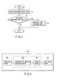
- FIG. 6 is a flowchart showing a processing flow of the smoothing and difference processing section 202.
- the smoothing and difference processing section 202 successively regards as the noted pixels the respective pixels in the image supplied from the image input section 201, and performs the processing described later.
- the smoothing and difference processing section 202 When the image is supplied from the image input section 201, the smoothing and difference processing section 202 performs smoothing processing (steps S21 to S23).
- This smoothing processing is similar to the processing of the steps S11 to S13 described in the first embodiment. That is, the smoothing and difference processing section 202 applies the median filter as the smoothing processing with respect to the noted pixel in the image acquired from the image input section 201, and calculates the intermediate value in the median filter (step S21). For example, in the smoothing and difference processing section 202 having the median filter with respect to 3x3 pixels, the intermediate value is calculated with respect to the image constituted of 3x3 pixels.
- the smoothing and difference processing section 202 calculates the magnitude (difference value) of the difference between the intermediate value and the luminance value of the noted pixel. On calculating the difference value between the intermediate value and the luminance value of the noted pixel, the smoothing and difference processing section 202 judges whether or not the calculated difference value is not less than a preset threshold value (step S22).
- the smoothing and difference processing section 202 leaves the luminance value of the noted pixel after smoothed as that of the noted pixel before smoothed.
- the smoothing and difference processing section 202 replaces the luminance value of the noted pixel after smoothed with the intermediate value (step S23).
- the smoothing and difference processing section 202 performs processing to calculate the difference value between the adjacent pixels as the processing of the difference between the pixels (step S24).
- the section calculates the difference value between the luminance value of the noted pixel and that of the pixel adjacent to the noted pixel.
- the processing of the difference between the pixels is calculated by the following equation 2.
- f ( x , y ) f ( x , y ) - f ( x - 1 , y ) , wherein f(x, y) denotes the luminance value of the noted pixel, and f(x-1, y) denotes the luminance value of the pixel adjacent to the noted pixel.
- the smoothing and difference processing section 202 checks whether or not the processing has ended with respect to all of the pixels in the image acquired from the image input section 201 (step S25).
- the smoothing and difference processing section 202 updates the noted pixel (step S26), and returns to the step S21. Accordingly, the smoothing and difference processing section 202 repeatedly performs processing similar to the above-described processing with respect to the next noted pixel.
- the smoothing and difference processing section 202 ends the smoothing and the processing of the difference between the pixels with respect to the whole image (i.e., all of the pixels in the image) acquired from the image input section 201.
- the image subjected to the smoothing and the processing of the difference between the pixels in this manner is supplied to the coding section 203.
- the processing of the difference between the pixels can be performed with respect to the image while retaining characteristics which are recognition objects such as image information in which the luminance value rapidly changes. Therefore, even in a case where the image information in which the luminance value rapidly changes is the characteristic which is the recognition object, the smoothing and difference processing section 202 can perform the processing of the difference between the pixels with respect to the image of a compression object smoothed while retaining the characteristics which are the recognition objects.
- the image of the compression object is subjected to smoothing processing to leave the luminance value of the noted pixel after smoothed as that of the noted pixel before smoothed in a case where the difference value between the intermediate luminance value and the luminance value of the noted pixel is not less than the predetermined threshold value, and to set the luminance value of the noted pixel after smoothed to the intermediate value in a case where the difference value between the intermediate luminance value and the luminance value of the noted pixel is less than the predetermined threshold value. Furthermore, the device performs the processing of the difference between the adjacent pixels in the smoothed image.
- the processing of the difference between the pixels can be performed with respect to the image smoothed while retaining the characteristics which are such recognition objects that the luminance value rapidly changes.
- redundancy can be imparted while retaining the characteristics which are the recognition objects, and a compression efficiency of the image can be raised.
- This third embodiment will be described mainly assuming a case where a character image is a characteristic which is a recognition object in an image regarded as a compression object.
- FIG. 7 schematically shows a constitution example of an image compression device 300 according to the third embodiment.
- the image compression device 300 comprises: an image input section 301; a characteristic extracting section 302; a gradation conversion processing section 303; a coding section 304; a data output section 305 and the like.
- the image input section 301, the coding section 304, and the data output section 305 are similar to the image input section 101, the coding section 103, and the data output section 104 in the above-described first embodiment. Therefore, detailed description of the image input section 301, coding section 304, and data output section 305 will be omitted.
- the characteristic extracting section 302 extracts characteristics as images which are recognition objects from the image supplied from the image input section 301.
- the characteristic extracting section 302 extracts the characteristics as the images of the recognition objects from a luminance value of each pixel constituting the image supplied from the image input section 301.
- the characteristic extracting section 302 outputs the extracted characteristics as the images of the recognition objects to the gradation conversion processing section 303.
- the image supplied from the image input section 301 is an image of a paper sheet which is an object of character recognition
- a pixel group (character region) constituting a character and a pixel group (background region) constituting a background are obtained as the characteristics from the image.
- the image of the paper sheet comprises the pixel group having a luminance value of the paper sheet itself as the background, and the pixel group having the luminance value of the character itself as the character.
- the luminance value of each pixel constituting the background and that of each pixel constituting the character are two maximums.
- the gradation conversion processing section 303 performs gradation conversion with respect to the image based on the characteristics of the image obtained by the characteristic extracting section 302. That is, the gradation conversion processing section 303 functions as a conversion processing section which performs conversion processing with respect to the image input from the image input section 301 and regarded as an object of compression processing.
- the gradation conversion processing section 303 performs such gradation conversion processing as to allocate a fixed value to each pixel of the image, for example, based on the characteristics of the image obtained by the characteristic extracting section 302.
- the gradation conversion processing section 303 outputs image data subjected to the gradation conversion processing to the coding section 304.
- the gradation conversion processing section 303 subjects to the gradation conversion processing a whole image (all of the pixels in the image) supplied from the image input section 301 based on two threshold values (Th1, Th2) supplied from the characteristic extracting section 302.
- FIGS. 8 and 9 show histograms of the luminance values in a certain image.
- FIG. 8 shows two maximum values (Max1, Max2) in the histogram of the luminance values.
- FIG. 9 shows two threshold values (Th1, Th2) in the histogram of the luminance values.
- the characteristic extracting section 302 prepares the histogram of the luminance values of the respective pixels in the image.
- the image supplied from the image input section 301 is the image of the paper sheet which is the object of the character recognition
- the characteristic extracting section 302 prepares the histogram shown in FIG. 8.
- the histogram shown in FIG. 8 has two maximum values (Max1, Max2). One maximum value (Max1) indicates a peak of the character region in the image. The other maximum value (Max2) indicates a peak of the background region in the image.
- the characteristic extracting section 302 extracts two maximum values from the prepared histogram.
- each pixel having the luminance value in the vicinity of the maximum value extracted from the histogram is the pixel of the character region or the pixel of the background region.
- each pixel having the luminance value in the vicinity of one maximum value (Max1) indicates the pixel group of the character region in the image.
- Each pixel having the luminance value in the vicinity of the other maximum value (Max2) indicates the pixel group of the background region in the image.
- the characteristic extracting section 302 judges the threshold values as the character region and the background region based on the maximum values extracted from the histogram.
- these threshold values a value distant from each maximum value by a predetermined value may be simply set as each threshold value (Th1, Th2), and a value corresponding to a certain accumulated value of the histogram may be set as each threshold value (Th1, Th2).
- the characteristic extracting section 302 supplies the judged threshold values (Th1, Th2) as the values indicating the characteristics of the image to the gradation conversion processing section 303.
- FIG. 10 is a diagram showing an example of the gradation conversion processing by the gradation conversion processing section 303.
- the pixel whose luminance value is smaller than the threshold value Th1 as the threshold value of the character region is converted into a predetermined luminance value as the luminance value of the pixel forming the character.
- the pixel whose luminance value is larger than the threshold value Th2 as the threshold value of the background region is converted into a predetermined luminance value as the luminance value of the pixel forming the background.
- redundancy can be imparted without losing the characteristics in the character region or the background region.
- a compression efficiency of the image can be raised without influencing the processing such as character recognition with respect to the compressed image.
- the characteristics which are objects of recognition processing are extracted from the acquired image, the image is subjected to the gradation conversion processing depending on the characteristics which are the objects of the recognition processing in the extracted image, and the image subjected to the gradation conversion processing is coded.
- the compression efficiency of the image can be raised while retaining the characteristics which are the objects of the recognition processing in the image which is the object of the compression processing.
- FIG. 11 schematically shows a constitution example of an image compression device 400 according to the fourth embodiment.
- the image compression device 400 according to the fourth embodiment is a modification of the third embodiment.
- the fourth embodiment will be described mainly assuming a case where a characteristic which is a recognition object in an image regarded as a compression object is a face image.
- the image compression device 400 comprises an image input section 401, a face region detecting section 402, a deviation value judgment section 403, a gradation conversion processing section 404, a coding section 405, and a data output section 406.
- the image input section 401, the gradation conversion processing section 404, the coding section 405, and the data output section 406 are similar to the image input section 301, the gradation conversion processing section 303, the coding section 304, and the data output section 305 in the third embodiment. Therefore, detailed description of the image input section 401, gradation conversion processing section 404, coding section 405, and data output section 406 will be omitted.
- the face region detecting section 402 performs processing to detect a face region of the face image from the image supplied from the image input section 401.
- the face region detecting section 402 supplies to the deviation value judgment section 403 information indicating the face region detected from the image supplied from the image input section 401.
- a method of extracting the face region may be used utilizing an inherent space method or a partial space method.
- the deviation value judgment section 403 judges the deviation value as a threshold value for use in gradation conversion processing by the gradation conversion processing section 404.
- the deviation value judgment section 403 supplies the judged deviation value as the threshold value to the gradation conversion processing section 404. It is to be noted that the deviation value judgment section 403 functions as a characteristic extracting section which performs characteristic extraction processing to extract the deviation value (threshold value) as the characteristic of the recognition object in the image of the compression object input by the image input section 401.
- the deviation value judgment section 403 judges the deviation value based on the luminance value of each pixel forming the face region detected by the face region detecting section 402.
- the deviation value is judged based on a minimum value (Min) and a maximum value (Max) of the luminance values of the respective pixels forming the face region. That is, when the face region detecting section 402 detects the face region, the deviation value judgment section 403 detects the maximum and minimum values from the luminance values of the respective pixels forming the face region detected by the face region detecting section 402.
- the deviation value judgment section 403 regards a luminance value which is smaller than the detected minimum value by a predetermined value as a first threshold value (Th1) as a first deviation value.
- the deviation value judgment section 403 regards a luminance value which is larger than the detected maximum value by a predetermined value as a second threshold value (Th2) as a second deviation value.
- the maximum and minimum values detected by the deviation value judgment section 403 may be statistically detected in a distribution of pixel values of the respective pixels forming the face region. That is, the deviation value judgment section 403 may detect the minimum and maximum values from the pixel values which are not less than a certain frequency in the distribution of the pixel values of the respective pixels forming the face region. In this case, the pixel value of the pixel which appears by an influence of noises or the like can be prevented from being detected as the minimum or maximum value.
- the gradation conversion processing section 404 performs the gradation conversion processing with respect to the image based on the threshold value judged by the deviation value judgment section 403. As described above, the threshold value as the deviation value is judged based on the minimum and maximum values of the face region. Therefore, the gradation conversion processing section 404 can perform the gradation conversion processing while retaining the pixel value of each pixel forming the face region which is the recognition object.
- a region other than the face region detected by the face region detecting section 402 is a region (background region) of a background image of the face image. That is, the pixel having a luminance value which is larger than the maximum value, or the pixel having a luminance value which is smaller than the minimum value is the pixel of the background region.
- the pixel whose luminance value is smaller than the threshold value (Th1) in the background region of the image is converted into a predetermined luminance value.
- the pixel whose luminance value is larger than the threshold value (Th2) in the background region of the image is converted into the predetermined luminance value.
- the gradation conversion processing can be performed even with respect to the image including the face image as the recognition object having a complicated distribution of the luminance values without influencing the face image as the recognition object.
- redundancy is imparted, and a compression efficiency can be enhanced while retaining characteristics as recognition objects.
- FIG. 12 shows an example of a histogram showing the distribution of the luminance values of the respective pixels forming the face region.
- FIG. 13 shows an example of a histogram showing the distribution of the pixel values of the respective pixels forming a whole image including the face region of FIG. 12.
- the luminance values of the respective pixels forming the face region are values ranging from the minimum value (Min) to the maximum value (Max).
- a distribution a appears in which the maximum is taken in the luminance values larger than the maximum value (Max) in addition to the distribution of the luminance values of the respective pixels forming the face region shown in FIG. 12.
- Each pixel forming the distribution a has a luminance value which is larger than the maximum value (Max). Therefore, each pixel forming the distribution a does not include any pixel that forms the face region.
- the distribution a in which the maximum is taken in the luminance values larger than the maximum value (Max) is supposed to be a distribution of the luminance values of the respective pixels forming the background region in the image. That is, the respective pixels forming the distribution a are the pixels of the background region totally unrelated to the face image which is the recognition object. Therefore, even when each pixel forming the distribution a is converted into a specific luminance value, any characteristic of the face image as the recognition object is not lost.
- the threshold value (Th1) shown in FIG. 13 is a value judged based on the minimum value (Min) shown in FIG. 12.
- the threshold value (Th1) is a luminance value smaller than the minimum value (Min).
- the threshold value (Th2) shown in FIG. 13 is a value judged based on the maximum value (Max) shown in FIG. 12.
- the threshold value (Th2) is a luminance value larger than the maximum value (Max).
- the image gradation-converted using the threshold values (Th1, Th2) the face image as the recognition object included in the image is retained. Moreover, the background region of the image is converted into a certain luminance value based on the threshold value. Therefore, the image of the background region can be provided with redundancy.
- the image of the compression object can be subjected to the conversion processing which imparts the redundancy for raising the compression efficiency while retaining the luminance value of each pixel forming the face region as the recognition object.
- the face region which is the object of the recognition processing is detected from the acquired image, the threshold value for the gradation conversion processing is judged based on the luminance value of each pixel forming the face region, the image is subjected to the gradation conversion processing by the threshold value, and the image subjected to the gradation conversion processing is coded.
- the compression efficiency of the image can be raised while retaining the face image which is the object of the recognition processing in the image which is the object of the compression processing.
- FIG. 14 schematically shows a constitution example of an image compression device 500 according to the fifth embodiment.
- the image compression device 500 comprises an image input section 501, a face region detecting section 502, a positioning section 503, a difference value calculating section 504, a coding section 505, a data output section 506 and the like.
- the coding section 505 and the data output section 506 are similar to the coding section 103 and the data output section 104 in the first embodiment. Therefore, detailed description of the coding section 505 and data output section 506 will be omitted. Additionally, the coding section 505 performs coding processing with respect to a difference image supplied from the difference value calculating section 504.
- the image input section 501 continuously inputs a plurality of images.
- the image input section 501 continuously inputs a plurality of images including characteristics which are objects of recognition processing.
- the image input section 501 continuously inputs a plurality of images including a face image as the characteristic which is the object of the recognition processing.
- the image input section 501 comprises, for example, a television camera or the like.
- the image input section 501 successively supplies each of the continuously input images to the face region detecting section 502.
- each of the images continuously input by the image input section 501 is digital image data in which values (pixel values) of pixels forming each image are represented by digital values.
- each of the images continuously input by the image input section 501 is digital image data including 512 pixels in a lateral direction and 512 pixels in a longitudinal direction.
- description will be given assuming that each image continuously input by the image input section 501 is image data in which the pixel value of each pixel is represented by a luminance value.
- each image continuously input by the image input section 501 may be image data in which the value (pixel value) of each pixel is represented by a density value.
- the face region detecting section 502 performs processing to detect a region (face region) of the face image with respect to each image successively supplied from the image input section 501. It is to be noted that the face detection processing performed with respect to each image by the face region detecting section 502 is similar to that by the face region detecting section 402 in the fourth embodiment. Therefore, detailed description of the face region detecting section 502 will be omitted.
- the positioning section 503 functions as a judgment processing section which judges characteristics of the image input by the image input section 501.
- the positioning section 503 judges the characteristics of the image input by the image input section 501, and selectively positions each image based on the judged characteristics of the image. That is, the positioning section 503 judges whether or not to perform positioning of the image and the previous image based on the face region of each image detected by the face region detecting section 502.
- the positioning section 503 supplies the image as such to the difference value calculating section 504.
- the positioning section 503 matches the position of the face region in the image with that of the face region in the immediately previous image. In this case, the positioning section 503 supplies to the difference value calculating section 504 the image in which the face region is positioned depending on the position of the face region in the immediately previous image.
- the positioning section 503 can perform positioning as the positioning of the face region, for example, using a position of a gravity of the face region detected by the face region detecting section 502.
- the face region detecting section 502 supplies to the positioning section 503 the information indicating a gravity position of the face region together with the information indicating the face region.
- the difference value calculating section 504 calculates an image (difference image) as the difference value between the previous and subsequent images continuously input by the image input section 501. That is, the difference value calculating section 504 calculates the difference image between each image and the immediately previous image.
- the difference value calculating section 504 calculates the difference image constituted of a difference value between the respective pixels based on a correspondence of the respective pixels in the previous and subsequent images depending on the characteristics of the image judged by the positioning section 503.
- the difference value calculating section 504 calculates the difference image between the positioned image and the immediately previous image especially with respect to the image positioned by the positioning section 503.
- the difference value calculating section 504 supplies the calculated difference image to the coding section 505.
- the value of the pixel in the difference image is "0".
- a compression efficiency of the difference image is high. That is, the more the pixels having the equal value in the same position exist in the previous and subsequent images, the higher the redundancy is. The compression efficiency is raised.
- FIG. 15A shows an example of an image including the face image input by the image input section 501.
- FIG. 15B shows an example of an image next to the image shown in FIG. 15A input by the image input section 501.
- FIG. 16A shows an example of an image including the face image input by the image input section 501.
- FIG. 16B shows an example of an image next to the image shown in FIG. 16A input by the image input section 501.
- a camera as the image input section 501 continuously photographs the image including the face image.
- a photographing position of the camera as the image input section 501 is fixed, and photographing conditions are the same, a background is photographed as the same image in the same position in a plurality of images photographed by the camera.
- the positioning section 503 matches the positions of the face regions in the previous and subsequent images in a case where the face region is large in the whole image.
- the positions of the face regions in the previous and subsequent images are matched, there are supposedly more pixels indicating "0" in the face region in the difference image between the previous and subsequent images.
- the position of the face region in the image shown in FIG. 16A is matched with that of the face region in the image shown in FIG. 16B to calculate the difference image, it is predicted that the value of each pixel easily indicates "0" in the face region shown by slant lines in FIG. 16B.
- the positioning section 503 judges whether or not to position the face regions in the previous and subsequent images depending on whether or not the size of the face region in the whole image is not less than a predetermined size.
- FIG. 17 is a flowchart showing the positioning processing by the positioning section 503.
- the positioning section 503 calculates the size of the face region as a ratio of the size of the face region occupying the whole image input by the image input section 501. It is to be noted that when the size of the whole image input by the image input section 501 is a fixed size, the size of the face region may be detected.
- the positioning section 503 judges whether or not the ratio of the face region occupying the whole image is not less than the preset threshold value (Th) (step S51). It is to be noted that when the size of the face region itself is detected, the positioning section 503 may judge whether or not the size of the face region is not less than the preset size.
- the positioning section 503 ends the processing without performing the positioning processing of the face regions in the previous and subsequent images.
- the positioning section 503 performs positioning processing of the face regions in the previous and subsequent images (step S52).
- the position of the face region in the image regarded as the processing object is matched with that (e.g., gravity position of the face region) of the face region in the immediately previous image.
- the positioning section 503 positions the face regions in the previous and subsequent images in a case where the size of the face region is not less than a predetermined threshold value, and does not position any image in a case where the size of the face region is less than the predetermined threshold value.
- the face regions in the previous and subsequent images are regarded as object regions of the difference in a case where the size of the face region is not less than the predetermined threshold value.
- the background regions in the previous and subsequent images are regarded as the object regions of the difference in a case where the size of the face region is less than the predetermined threshold value.
- the positioning section 503 switches the region regarded as the object of the difference to the face region or the background region depending on the size of the face region.
- the difference value calculating section 504 can calculate the difference image having a high compression efficiency irrespective of the characteristics of the image input by the image input section.
- the face regions are detected from a plurality of continuously acquired images, respectively, the previous and subsequent images are positioned depending on the size of the detected face region, the difference image is calculated from the positioned previous and subsequent images, and the calculated difference image is coded.
- the redundancy in the difference image is improved, and the compression efficiency of the image can be raised based on the characteristics of the respective continuous images.
Applications Claiming Priority (1)
| Application Number | Priority Date | Filing Date | Title |
|---|---|---|---|
| JP2005015629A JP2006202209A (ja) | 2005-01-24 | 2005-01-24 | 画像圧縮方法および画像圧縮装置 |
Publications (2)
| Publication Number | Publication Date |
|---|---|
| EP1684520A2 true EP1684520A2 (de) | 2006-07-26 |
| EP1684520A3 EP1684520A3 (de) | 2008-12-31 |
Family
ID=36218473
Family Applications (1)
| Application Number | Title | Priority Date | Filing Date |
|---|---|---|---|
| EP20050019462 Withdrawn EP1684520A3 (de) | 2005-01-24 | 2005-09-07 | Methode und Apparat für die Bildkompression |
Country Status (4)
| Country | Link |
|---|---|
| US (1) | US20060165305A1 (de) |
| EP (1) | EP1684520A3 (de) |
| JP (1) | JP2006202209A (de) |
| CA (1) | CA2518988A1 (de) |
Families Citing this family (6)
| Publication number | Priority date | Publication date | Assignee | Title |
|---|---|---|---|---|
| JP4814826B2 (ja) * | 2007-03-30 | 2011-11-16 | 株式会社イクス | 画像処理装置及び画像処理方法 |
| CN102325257A (zh) * | 2007-07-20 | 2012-01-18 | 富士胶片株式会社 | 图像处理设备和图像处理方法 |
| JP4927047B2 (ja) * | 2008-08-29 | 2012-05-09 | 富士通フロンテック株式会社 | 画像処理装置、画像処理方法および画像処理プログラム |
| US8805000B2 (en) * | 2011-08-23 | 2014-08-12 | Honeywell International Inc. | Mobile energy audit system and method |
| CN104025080B (zh) * | 2011-11-04 | 2017-05-03 | 富士通株式会社 | 对照控制程序、对照控制装置以及对照控制方法 |
| KR101499461B1 (ko) * | 2013-06-28 | 2015-03-16 | 전남대학교산학협력단 | 히스토그램 압축을 이용한 히스토그램 평활화 장치 |
Citations (3)
| Publication number | Priority date | Publication date | Assignee | Title |
|---|---|---|---|---|
| US5630036A (en) | 1992-11-02 | 1997-05-13 | Fujitsu Limited | Image data compression method involving deleting data in areas where predicted color value, based on color change between adjacent pixels, is small, and image data processing device implementing same method |
| EP0845716A2 (de) | 1996-11-28 | 1998-06-03 | Toshiba Corporation | Bildverarbeitungsgerät mit Bildbereichserkennungsfunktion und Bildverarbeitungsverfahren |
| EP1150513A1 (de) | 2000-04-28 | 2001-10-31 | Texas Instruments Incorporated | Vorverarbeitung für bewegungskompensierte prädiktive Bildcodierung |
Family Cites Families (20)
| Publication number | Priority date | Publication date | Assignee | Title |
|---|---|---|---|---|
| DE1762412A1 (de) * | 1968-06-12 | 1970-05-06 | Telefunken Patent | Einrichtung in einer Datenverarbeitungsanlage mit einer Analog-Digital-Umsetzungsstufe und einem dieser nachgeschalteten Digitalspeicher |
| EP0238045B1 (de) * | 1986-03-17 | 1996-06-19 | Fuji Photo Film Co., Ltd. | Verfahren zur Glättung von Bildsignalen |
| US5463470A (en) * | 1991-10-09 | 1995-10-31 | Fuji Photo Film Co., Ltd. | Methods of collecting photometric image data and determining light exposure by extracting feature image data from an original image |
| US5657403A (en) * | 1992-06-01 | 1997-08-12 | Cognex Corporation | Vision coprocessing |
| US5446501A (en) * | 1992-10-22 | 1995-08-29 | Accom, Incorporated | Three-dimensional median and recursive filtering apparatus and method for video image enhancement |
| US5367629A (en) * | 1992-12-18 | 1994-11-22 | Sharevision Technology, Inc. | Digital video compression system utilizing vector adaptive transform |
| US5715335A (en) * | 1993-12-02 | 1998-02-03 | U.S. Philips Corporation | Noise reduction |
| JPH07221987A (ja) * | 1994-02-04 | 1995-08-18 | Canon Inc | 画像処理装置 |
| JP3461626B2 (ja) * | 1995-07-28 | 2003-10-27 | シャープ株式会社 | 特定画像領域抽出方法及び特定画像領域抽出装置 |
| JPH10108202A (ja) * | 1996-09-30 | 1998-04-24 | Kiyoaki Kobayashi | 画像用及び印字用等のデータの圧縮方法 |
| US5832115A (en) * | 1997-01-02 | 1998-11-03 | Lucent Technologies Inc. | Ternary image templates for improved semantic compression |
| JP3881439B2 (ja) * | 1998-01-23 | 2007-02-14 | シャープ株式会社 | 画像処理装置 |
| US6735341B1 (en) * | 1998-06-18 | 2004-05-11 | Minolta Co., Ltd. | Image processing device and method and recording medium for recording image processing program for same |
| US7099041B1 (en) * | 1999-03-02 | 2006-08-29 | Seiko Epson Corporation | Image data background determining apparatus image data background determining method, and medium recording thereon image data background determination control program |
| US6724945B1 (en) * | 2000-05-24 | 2004-04-20 | Hewlett-Packard Development Company, L.P. | Correcting defect pixels in a digital image |
| US7206453B2 (en) * | 2001-05-03 | 2007-04-17 | Microsoft Corporation | Dynamic filtering for lossy compression |
| JP4177598B2 (ja) * | 2001-05-25 | 2008-11-05 | 株式会社東芝 | 顔画像記録装置、情報管理システム、顔画像記録方法、及び情報管理方法 |
| US7031540B2 (en) * | 2001-09-12 | 2006-04-18 | Mobitv, Inc. | Transformation to increase the lempel-ziv compressibility of images with minimal visual distortion |
| US6993181B2 (en) * | 2001-09-19 | 2006-01-31 | Kabushiki Kaisha Toshiba | Image compression decoding apparatus and method thereof |
| US20040260782A1 (en) * | 2003-01-31 | 2004-12-23 | Affleck Rhett L. | Data communication in a laboratory environment |
-
2005
- 2005-01-24 JP JP2005015629A patent/JP2006202209A/ja active Pending
- 2005-09-07 EP EP20050019462 patent/EP1684520A3/de not_active Withdrawn
- 2005-09-09 CA CA 2518988 patent/CA2518988A1/en not_active Abandoned
- 2005-09-14 US US11/225,100 patent/US20060165305A1/en not_active Abandoned
Patent Citations (3)
| Publication number | Priority date | Publication date | Assignee | Title |
|---|---|---|---|---|
| US5630036A (en) | 1992-11-02 | 1997-05-13 | Fujitsu Limited | Image data compression method involving deleting data in areas where predicted color value, based on color change between adjacent pixels, is small, and image data processing device implementing same method |
| EP0845716A2 (de) | 1996-11-28 | 1998-06-03 | Toshiba Corporation | Bildverarbeitungsgerät mit Bildbereichserkennungsfunktion und Bildverarbeitungsverfahren |
| EP1150513A1 (de) | 2000-04-28 | 2001-10-31 | Texas Instruments Incorporated | Vorverarbeitung für bewegungskompensierte prädiktive Bildcodierung |
Also Published As
| Publication number | Publication date |
|---|---|
| JP2006202209A (ja) | 2006-08-03 |
| US20060165305A1 (en) | 2006-07-27 |
| CA2518988A1 (en) | 2006-07-24 |
| EP1684520A3 (de) | 2008-12-31 |
Similar Documents
| Publication | Publication Date | Title |
|---|---|---|
| US7634150B2 (en) | Removing ringing and blocking artifacts from JPEG compressed document images | |
| US8086050B2 (en) | Multi-resolution segmentation and fill | |
| EP1684520A2 (de) | Methode und Apparat für die Bildkompression | |
| KR101907414B1 (ko) | 촬영 이미지 기반의 문자 인식 장치 및 방법 | |
| Ravi et al. | Compression noise based video forgery detection | |
| US20080118158A1 (en) | Image area extraction method, image reconstruction method using the extraction result and apparatus thereof | |
| KR101704775B1 (ko) | 다중해상도 영상 처리 장치 및 영상 처리 방법 | |
| US8260067B2 (en) | Detection technique for digitally altered images | |
| JP4257202B2 (ja) | 画像ブロック内のエッジを検出する装置 | |
| KR101244688B1 (ko) | 화상의 계조 해상도를 향상시키는 인코딩 및 디코딩 방법,그리고 이를 이용하는 인쇄시스템 | |
| US20040218790A1 (en) | Print segmentation system and method | |
| EP2383697A1 (de) | Vorrichtung zur extraktion von bilddentifikatoren | |
| US20090110313A1 (en) | Device for performing image processing based on image attribute | |
| US8275198B2 (en) | Image processing apparatus, image processing method and computer readable medium with compression processing for each color | |
| EP1457927A2 (de) | Vorrichtung und Verfahren zur Detektion von Bildschärfeverzerrung | |
| EP1006714A2 (de) | Verfahren zur Bearbeitung von gemischten Bildrasterinhaltsebenen | |
| Hämmerle-Uhl et al. | Improving compressed iris recognition accuracy using jpeg2000 roi coding | |
| US8213713B2 (en) | Image processing apparatus and computer readable medium | |
| JP4006276B2 (ja) | 画像認識方法、画像認識装置及びコンピュータプログラム | |
| JP4078136B2 (ja) | 画像認識方法、画像認識装置及びコンピュータプログラム | |
| JP4742632B2 (ja) | 画像処理装置、画像処理方法及びプログラム | |
| JP4228905B2 (ja) | 画像処理装置及びプログラム | |
| JP4078135B2 (ja) | 画像認識方法、画像認識装置及びコンピュータプログラム | |
| JP2005018466A (ja) | 画像領域の抽出及び画像の再生 | |
| JP2005244649A (ja) | 画像処理装置 |
Legal Events
| Date | Code | Title | Description |
|---|---|---|---|
| PUAI | Public reference made under article 153(3) epc to a published international application that has entered the european phase |
Free format text: ORIGINAL CODE: 0009012 |
|
| 17P | Request for examination filed |
Effective date: 20050907 |
|
| AK | Designated contracting states |
Kind code of ref document: A2 Designated state(s): AT BE BG CH CY CZ DE DK EE ES FI FR GB GR HU IE IS IT LI LT LU LV MC NL PL PT RO SE SI SK TR |
|
| AX | Request for extension of the european patent |
Extension state: AL BA HR MK YU |
|
| RIC1 | Information provided on ipc code assigned before grant |
Ipc: G06T 5/00 20060101ALI20080313BHEP Ipc: G06K 9/00 20060101ALI20080313BHEP Ipc: H04N 7/26 20060101AFI20060509BHEP |
|
| PUAL | Search report despatched |
Free format text: ORIGINAL CODE: 0009013 |
|
| AK | Designated contracting states |
Kind code of ref document: A3 Designated state(s): AT BE BG CH CY CZ DE DK EE ES FI FR GB GR HU IE IS IT LI LT LU LV MC NL PL PT RO SE SI SK TR |
|
| AX | Request for extension of the european patent |
Extension state: AL BA HR MK YU |
|
| RIC1 | Information provided on ipc code assigned before grant |
Ipc: H04N 1/40 20060101ALI20081124BHEP Ipc: G06T 5/00 20060101ALI20081124BHEP Ipc: G06K 9/00 20060101ALI20081124BHEP Ipc: H04N 7/26 20060101AFI20060509BHEP |
|
| 17Q | First examination report despatched |
Effective date: 20090213 |
|
| AKX | Designation fees paid |
Designated state(s): DE FR IT |
|
| STAA | Information on the status of an ep patent application or granted ep patent |
Free format text: STATUS: THE APPLICATION IS DEEMED TO BE WITHDRAWN |
|
| 18D | Application deemed to be withdrawn |
Effective date: 20120919 |