EP1684057A1 - Apparatus and method for detecting hot spots in an electric power conductor - Google Patents
Apparatus and method for detecting hot spots in an electric power conductor Download PDFInfo
- Publication number
- EP1684057A1 EP1684057A1 EP06001205A EP06001205A EP1684057A1 EP 1684057 A1 EP1684057 A1 EP 1684057A1 EP 06001205 A EP06001205 A EP 06001205A EP 06001205 A EP06001205 A EP 06001205A EP 1684057 A1 EP1684057 A1 EP 1684057A1
- Authority
- EP
- European Patent Office
- Prior art keywords
- power conductor
- electrically insulative
- temperature probe
- temperature
- conductive material
- Prior art date
- Legal status (The legal status is an assumption and is not a legal conclusion. Google has not performed a legal analysis and makes no representation as to the accuracy of the status listed.)
- Withdrawn
Links
- 239000004020 conductor Substances 0.000 title claims abstract description 128
- 238000000034 method Methods 0.000 title claims description 17
- 239000000523 sample Substances 0.000 claims abstract description 52
- 239000000463 material Substances 0.000 claims abstract description 6
- 238000012544 monitoring process Methods 0.000 claims description 10
- 230000008859 change Effects 0.000 claims description 6
- 230000004044 response Effects 0.000 claims description 4
- 238000002955 isolation Methods 0.000 abstract description 2
- 230000004888 barrier function Effects 0.000 description 4
- 239000000853 adhesive Substances 0.000 description 3
- 230000001070 adhesive effect Effects 0.000 description 3
- 238000001514 detection method Methods 0.000 description 2
- 230000004048 modification Effects 0.000 description 2
- 238000012986 modification Methods 0.000 description 2
- 239000007858 starting material Substances 0.000 description 2
- 239000004825 One-part adhesive Substances 0.000 description 1
- 230000008901 benefit Effects 0.000 description 1
- 239000011521 glass Substances 0.000 description 1
- 238000011065 in-situ storage Methods 0.000 description 1
- 238000007689 inspection Methods 0.000 description 1
- 238000009434 installation Methods 0.000 description 1
- 238000004519 manufacturing process Methods 0.000 description 1
- 239000002184 metal Substances 0.000 description 1
- 238000012806 monitoring device Methods 0.000 description 1
- 230000000737 periodic effect Effects 0.000 description 1
- 229920001225 polyester resin Polymers 0.000 description 1
- 239000004645 polyester resin Substances 0.000 description 1
Images


Classifications
-
- G—PHYSICS
- G01—MEASURING; TESTING
- G01K—MEASURING TEMPERATURE; MEASURING QUANTITY OF HEAT; THERMALLY-SENSITIVE ELEMENTS NOT OTHERWISE PROVIDED FOR
- G01K1/00—Details of thermometers not specially adapted for particular types of thermometer
- G01K1/16—Special arrangements for conducting heat from the object to the sensitive element
-
- G—PHYSICS
- G01—MEASURING; TESTING
- G01K—MEASURING TEMPERATURE; MEASURING QUANTITY OF HEAT; THERMALLY-SENSITIVE ELEMENTS NOT OTHERWISE PROVIDED FOR
- G01K1/00—Details of thermometers not specially adapted for particular types of thermometer
- G01K1/14—Supports; Fastening devices; Arrangements for mounting thermometers in particular locations
Definitions
- This invention relates to on-line detection of hot spots in electric power conductors.
- a potential problem in electric power equipment is the occurrence of hot spots in the power conductors within enclosures that can lead to failures. Such hot spots occur at bolted joints in the power conductors and at terminals and are often attributable to poor workmanship or vibrations that over time result in loosening of the joints.
- the power conductors in electrical equipment are continuously monitored for hot spots by the use of temperature sensors that are applied directly in physical contact with the conductors.
- the temperature sensors comprise an electrically insulative support member having a contact surface for engaging the power conductor with a cavity. Electrically insulative thermally conductive material in the cavity extends to the contact surface to bring the material into surface-to-surface contact with the power conductor. A temperature probe is embedded in the electrically insulative thermally conductive material spaced by the electrically insulative thermally conductive material from the power conductor sufficiently to be electrically isolated.
- the electrically insulative thermally conductive material has sufficient thermal conductivity to heat the temperature probe to within a specified tolerance of the temperature of the power conductor.
- the temperature probe can be for instance a resistance temperature detector or a thermocouple.
- the temperature probe could be spaced from the power conductor by a sufficient portion of the electrically insulative thermally conductive material to provide a basic impulse level of at least about 60 kV. Other suitable spacings for the temperature probe may be acceptable at various corresponding basic impulse levels.
- the electrically insulative support member can have at least one fastener member embedded in the contact surface and can be a support for the power conductor.
- the support member can have at least two fastener members for securing the joint.
- the support member can have a base section containing the cavity and a sleeve through which electrical leads for the temperature probe extend. If the supporting material possesses adequate thermal conductivity, then the temperature probe may be molded directly into the body of the support at the time of its manufacture.
- aspects of the invention can also be applied to electric power equipment having multiple phase conductors in which case electrically insulative thermally conductive material is placed in surface-to-surface contact with each of the phase conductors.
- a temperature probe encapsulated in the electrically insulative thermally conductive material generates a sensor signal for each phase conductor.
- a controller receives the sensor signals generated by each temperature probe and generates an alarm in response to selected temperature criteria. For instance, the controller can generate an alarm when any of the sensor signals exceeds a selected threshold. Alternatively, the controller can generate an alarm when there is an imbalance in the sensor signals monitoring the temperature of the power conductors.
- the invention also embraces a method of detecting hot spots in a conductor of electric power equipment that comprises: forming a cavity adjacent to the power conductor, inserting a temperature probe into the cavity, filling the cavity and encapsulating the temperature probe with an electrically insulative thermally conductive material, and curing the electrically insulative thermally conductive material while in surface-to-surface contact with the power conductor.
- the temperature probe is spaced from the power conductor sufficiently to electrically isolate the temperature probe from the power conductor and the electrically insulative thermally conductive material has sufficient thermal conductivity to heat the temperature probe to within a specified tolerance of the temperature of the power conductor:
- the cavity can be formed in an electrically and thermally insulative material that remains in place after curing.
- the temperature probe is spaced at least about one inch (25.4 mm) from the power conductor and the electrically insulative thermally conductive material can be a material, such as an adhesive, having a coefficient of thermal conductivity of at least about 1 watt per meter Kelvin.
- the invention also embraces a method of on-line monitoring of hot spots in power equipment having a power conductor housed in an electrical enclosure that comprises: placing in surface-to-surface contact with the power conductor within the electrical enclosure an electrically insulative thermally conductive material in which is encapsulated a temperature probe that provides a sensor signal indicative of temperature and that is spaced from the power conductor sufficiently to be electrically isolated therefrom.
- the method further includes monitoring the sensor signal and generating an alarm in response to selected temperature characteristics of the power conductor indicated by the sensor signal.
- the selected temperature characteristics can be a temperature of the power conductor above a selected level. It can also be a function of time and current carried by the conductor.
- the selected characteristic can be a selected increase in temperature over a selected time interval.
- an electrically insulative thermally conductive material in which is encapsulated a temperature probe is placed in surface-to-surface contact with each of the plurality of phase conductors and an alarm is generated when the sensor signals indicate an imbalance in temperature in the plurality of phase conductors.
- a single sensor may be positioned in appropriate proximity to provide temperature indication of multiple conductors, which has the benefit of reducing the total number of sensors required in a system.
- the invention is directed to monitors for detecting hot spots in electric power systems. It will be described as applied to medium-voltage electric power systems; however, it will be evident that it also has application to other power systems such as, for example, low-voltage power distribution systems.
- a monitor 1 for detecting hot spots in electric power conductors includes an electrically and thermally insulative support member 3 that in this particular embodiment is cylindrical.
- An end contact surface 5 has a cavity 7 that, again in the exemplary embodiment, can be cylindrical.
- a pair of fastener members 9, which in the exemplary embodiment are threaded inserts, are seated in bores 11 in the contact surface 5.
- Other types of fastener members 9 could be used, such as studs, which would project above the contact surface 5.
- a temperature probe 13, such as a resistance temperature detector (RTD) or a thermocouple, is embedded in an electrically insulative thermally conductive material 15 that fills the cavity 7 so that it is flush with the contact surface 5.
- RTD resistance temperature detector
- thermocouple is embedded in an electrically insulative thermally conductive material 15 that fills the cavity 7 so that it is flush with the contact surface 5.
- the temperature probe has a pair of electrical leads 17 that are directed out of the support member 3 so that they are spaced from the contact surface 5.
- the support member 3 has a base section 19 and an extension or sleeve 21 through which the electrical leads 17 extend.
- FIG. 2 illustrates a lap joint 23 between a pair of conductors 25 in the form of flat bus bars.
- the lap joint 23 is secured by bolts 27 that would typically be engaged by nuts (not shown) or would engage threaded inserts in a bus support.
- the support member 3 replaces such nuts or is incorporated into the bus support and also facilitates monitoring the lap joint 23 for hot spots.
- the bolts 27 engage the threaded inserts 9 in the monitor 1 to complete the lap joint and to press the electrically insulative thermally conductive material 15 into surface-to-surface contact with the underside of the lower power conductor 25.
- the temperature probe 13 is embedded in the electrically insulative thermally conductive material 15 and spaced by a distance, t, from the surface-to-surface contact with the conductor 25 sufficient that the temperature probe 13 is electrically isolated from the conductor 25.
- the electrically insulative thermally conductive material 15 has a thermal conductivity sufficient to heat the temperature probe 13 sufficiently to substantiate trends in temperature change in the power conductor 25.
- the electrically insulative thermally conductive material 15 has a thermal conductivity of at least about 1 Watt/m Kelvin. In this manner then, the temperature probe 13 is capable of detecting hot spots in the conductor such as would occur at the lap joint 23.
- the sleeve 21 has a length sufficient to provide the electrical leads 17 for the temperature probe 13 with a standoff distance (h) sufficient to protect the leads from flashover from the conductors 25.
- the electrically insulative thermally conductive material 15 was a thermally conductive adhesive manufactured by Dow Coming Corporation identified by their number 3-6751. This is a two part adhesive with a thermal conductivity of 1.1 watts/m Kelvin. Dow Coming product 3-6752; a one part adhesive, had a better thermal conductivity of 1.7 watts/m Kelvin but this product is more viscous and more difficult to work with.
- the diameter of the cavity 7 was 1 ⁇ 2 inch (12.7 mm) and the tip of the temperature probe 13 was one inch (25.4 mm) from the contact surface of the electrically insulated thermally conductive material 15.
- the standoff height (h) was three inches (76.2 mm).
- the temperature probe method indicated a temperature within approximately 5% of the actual bus temperature with a rate of change of 15 degrees Kelvin or less per hour. The rate of change is typically below 15 degrees Kelvin with the exception of initial start up of equipment.
- the support member 3 was a glass polyester resin. When used with medium voltage equipment such as medium voltage starters, the standoff distance (h) should meet the Underwriters Laboratory Standard UL347 of 60 kV (Basic Impulse Level) for high voltage industrial control equipment.
- the invention can be applied to a conventional support member 3 a commonly used to support bus bars in medium voltage applications to provide the monitor 1a.
- a hole 29 is bored through the insulative support member 3a.
- the temperature probe 13 can be positioned within this bore 29 at the proper distance from the upper contact surface 5a and held in place while the electrically insulative thermally conductive material 15 is injected into the bore 29.
- the support member 3a can be used to simultaneously support power conductors and monitor for hot spots.
- the height, h, of the support member 3a provides the appropriate standoff distance for the probe electrical leads 17.
- the inventory of support members 3a can be modified as shown in Figure 3 or the modification can be done in situ for an existing installation.
- FIG. 4 Another embodiment of the monitor 1b in accordance with aspects of the invention is shown in Figures 4 and 5.
- the support member 3b has only a single fastener member 9 in the form of a threaded insert embedded in the contact surface 5b.
- the sleeve 21b can be of reduced diameter from the diameter of the base section 19b.
- Such a monitor 1b is suitable, for instance, for use with a terminal conductor 31 for a piece of power equipment 33.
- the single threaded insert 9 receives a single bolt 27 that secures the terminal conductor 31 to a power conductor 25 while also positioning the temperature probe 13 for monitoring hot spots at the joint 23b between a terminal conductor 31 and the power conductor 25.
- Figure 6 illustrates application of the invention to a three phase electric power system 35 having the three phase conductors 25A, 25B and 25C housed within a metal enclosure 37.
- the monitoring system 39 includes the three monitors 1A, 1B and 1C having electrically insulative support members 3A, 3B and 3C bolted to joints 23A, 23B and 23C in the respective phase conductors.
- the leads 17A, 17B and 17C for each of the monitors provide sensor signals to a controller 41.
- the controller 41 analyzes the sensor signals for temperature/time characteristics indicative of a hot spot. For instance, the controller 41 can alarm on any one of the sensor signals indicating a temperature above a threshold value, or a designated change in temperature.
- the controller 41 could alarm on an imbalance of a selected level between the signals from the respective phase monitors.
- the monitor system 39 can include a local display 43 for providing a man-machine interface. Additionally, or in place of this display 43, the controller 39 can provide readouts and alarms to remote monitoring devices. In addition, the controller can simultaneously monitor signals from multiple additional sensors.
Landscapes
- Physics & Mathematics (AREA)
- General Physics & Mathematics (AREA)
- Testing Electric Properties And Detecting Electric Faults (AREA)
- Testing Of Short-Circuits, Discontinuities, Leakage, Or Incorrect Line Connections (AREA)
- Measuring Temperature Or Quantity Of Heat (AREA)
Abstract
Description
- This invention relates to on-line detection of hot spots in electric power conductors.
- A potential problem in electric power equipment, such as, for example, switchgear and starters for large motors, is the occurrence of hot spots in the power conductors within enclosures that can lead to failures. Such hot spots occur at bolted joints in the power conductors and at terminals and are often attributable to poor workmanship or vibrations that over time result in loosening of the joints.
- The possibility of such hot spots has induced many operators to resort to periodic inspections. The known state of the art in hot spot detection in electrical equipment is through infrared (IR) scanning. This requires removal of barriers and covers. The practice is expensive, time consuming, hit or miss, arid is discrete and not continuous. In many cases, it requires temporary outages for removal of isolation barriers that obstruct IR scanning range. This practice exposes the operator to high voltages when safety barriers are removed on energized equipment. In some cases, many parts that have a potential of failing are not optically accessible while the equipment is energized. As IR scanning must be performed while the system is energized, the inspector must wear special clothing to protect against possible flashover. As an alternative to IR scanning, the system can be deenergized and checked for loose joints, which results in loss of equipment use, and again typically requiring the removal of barriers and covers, and the associated risk that they may not be properly replaced or may not be replaced at all.
- There is a need, therefore, for improved apparatus and methods of checking for hot spots in electric power equipment, and preferably for on-line techniques that provide real time continuous monitoring for hot spots.
- In accordance with the invention, the power conductors in electrical equipment are continuously monitored for hot spots by the use of temperature sensors that are applied directly in physical contact with the conductors. In accordance with aspects of the invention, the temperature sensors comprise an electrically insulative support member having a contact surface for engaging the power conductor with a cavity. Electrically insulative thermally conductive material in the cavity extends to the contact surface to bring the material into surface-to-surface contact with the power conductor. A temperature probe is embedded in the electrically insulative thermally conductive material spaced by the electrically insulative thermally conductive material from the power conductor sufficiently to be electrically isolated. The electrically insulative thermally conductive material has sufficient thermal conductivity to heat the temperature probe to within a specified tolerance of the temperature of the power conductor. The temperature probe can be for instance a resistance temperature detector or a thermocouple. In accordance with certain aspects of the invention, the temperature probe could be spaced from the power conductor by a sufficient portion of the electrically insulative thermally conductive material to provide a basic impulse level of at least about 60 kV. Other suitable spacings for the temperature probe may be acceptable at various corresponding basic impulse levels.
- In accordance with additional aspects of the invention, the electrically insulative support member can have at least one fastener member embedded in the contact surface and can be a support for the power conductor. When a pair of power conductors form a joint, the support member can have at least two fastener members for securing the joint. In accordance with additional aspects, the support member can have a base section containing the cavity and a sleeve through which electrical leads for the temperature probe extend. If the supporting material possesses adequate thermal conductivity, then the temperature probe may be molded directly into the body of the support at the time of its manufacture.
- Aspects of the invention can also be applied to electric power equipment having multiple phase conductors in which case electrically insulative thermally conductive material is placed in surface-to-surface contact with each of the phase conductors. A temperature probe encapsulated in the electrically insulative thermally conductive material generates a sensor signal for each phase conductor. In this embodiment, a controller receives the sensor signals generated by each temperature probe and generates an alarm in response to selected temperature criteria. For instance, the controller can generate an alarm when any of the sensor signals exceeds a selected threshold. Alternatively, the controller can generate an alarm when there is an imbalance in the sensor signals monitoring the temperature of the power conductors.
- The invention also embraces a method of detecting hot spots in a conductor of electric power equipment that comprises: forming a cavity adjacent to the power conductor, inserting a temperature probe into the cavity, filling the cavity and encapsulating the temperature probe with an electrically insulative thermally conductive material, and curing the electrically insulative thermally conductive material while in surface-to-surface contact with the power conductor. The temperature probe is spaced from the power conductor sufficiently to electrically isolate the temperature probe from the power conductor and the electrically insulative thermally conductive material has sufficient thermal conductivity to heat the temperature probe to within a specified tolerance of the temperature of the power conductor: In accordance with an aspect of the invention, the cavity can be formed in an electrically and thermally insulative material that remains in place after curing. In an embodiment of the invention, the temperature probe is spaced at least about one inch (25.4 mm) from the power conductor and the electrically insulative thermally conductive material can be a material, such as an adhesive, having a coefficient of thermal conductivity of at least about 1 watt per meter Kelvin.
- The invention also embraces a method of on-line monitoring of hot spots in power equipment having a power conductor housed in an electrical enclosure that comprises: placing in surface-to-surface contact with the power conductor within the electrical enclosure an electrically insulative thermally conductive material in which is encapsulated a temperature probe that provides a sensor signal indicative of temperature and that is spaced from the power conductor sufficiently to be electrically isolated therefrom. The method further includes monitoring the sensor signal and generating an alarm in response to selected temperature characteristics of the power conductor indicated by the sensor signal. The selected temperature characteristics can be a temperature of the power conductor above a selected level. It can also be a function of time and current carried by the conductor. In accordance with another aspect of the invention, the selected characteristic can be a selected increase in temperature over a selected time interval. Where the power equipment is multi-phase having a plurality of phase conductors within the enclosure, an electrically insulative thermally conductive material in which is encapsulated a temperature probe is placed in surface-to-surface contact with each of the plurality of phase conductors and an alarm is generated when the sensor signals indicate an imbalance in temperature in the plurality of phase conductors. A single sensor may be positioned in appropriate proximity to provide temperature indication of multiple conductors, which has the benefit of reducing the total number of sensors required in a system.
- A full understanding of the invention can be gained from the following description of the preferred embodiments when read in conjunction with the accompanying drawings in which:
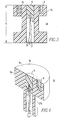
- Figure 1 is an isometric view of a hot spot detector in accordance with aspects of the invention.
- Figure 2 is a vertical cross section through the hot spot detector of Figure 1 shown mounted to monitor for hot spots at a lap joint between conductors of an electric power system.
- Figure 3 is a vertical cross section through a bus bar support adapted to incorporate aspects of the invention.
- Figure 4 is an isometric view of another embodiment of the invention which may be used to monitor hot spots at terminals in an electric power distribution system.
- Figure 5 is a vertical cross section through the hot spot monitor of Figure 4 shown in place for detecting hot spots in an electric power conductor at a terminal in an electric power distribution system.
- Figure 6 is a schematic view showing aspects of the invention applied to three-phase equipment in an electric power system.
- The invention is directed to monitors for detecting hot spots in electric power systems. It will be described as applied to medium-voltage electric power systems; however, it will be evident that it also has application to other power systems such as, for example, low-voltage power distribution systems.
- Turning to Figures 1 and 2, one embodiment of a
monitor 1 for detecting hot spots in electric power conductors includes an electrically and thermally insulative support member 3 that in this particular embodiment is cylindrical. Anend contact surface 5 has a cavity 7 that, again in the exemplary embodiment, can be cylindrical. A pair offastener members 9, which in the exemplary embodiment are threaded inserts, are seated inbores 11 in thecontact surface 5. Other types offastener members 9 could be used, such as studs, which would project above thecontact surface 5. Atemperature probe 13, such as a resistance temperature detector (RTD) or a thermocouple, is embedded in an electrically insulative thermallyconductive material 15 that fills the cavity 7 so that it is flush with thecontact surface 5. The temperature probe has a pair ofelectrical leads 17 that are directed out of the support member 3 so that they are spaced from thecontact surface 5. In the embodiment of Figures 1 and 2, the support member 3 has abase section 19 and an extension orsleeve 21 through which the electrical leads 17 extend. - Figure 2 illustrates a
lap joint 23 between a pair ofconductors 25 in the form of flat bus bars. Thelap joint 23 is secured bybolts 27 that would typically be engaged by nuts (not shown) or would engage threaded inserts in a bus support. In accordance with the invention, the support member 3 replaces such nuts or is incorporated into the bus support and also facilitates monitoring thelap joint 23 for hot spots. As shown, thebolts 27 engage the threadedinserts 9 in themonitor 1 to complete the lap joint and to press the electrically insulative thermallyconductive material 15 into surface-to-surface contact with the underside of thelower power conductor 25. - The
temperature probe 13 is embedded in the electrically insulative thermallyconductive material 15 and spaced by a distance, t, from the surface-to-surface contact with theconductor 25 sufficient that thetemperature probe 13 is electrically isolated from theconductor 25. At the same time, the electrically insulative thermallyconductive material 15 has a thermal conductivity sufficient to heat thetemperature probe 13 sufficiently to substantiate trends in temperature change in thepower conductor 25. In this regard, it is preferred that the electrically insulative thermallyconductive material 15 has a thermal conductivity of at least about 1 Watt/m Kelvin. In this manner then, thetemperature probe 13 is capable of detecting hot spots in the conductor such as would occur at the lap joint 23. Thesleeve 21 has a length sufficient to provide the electrical leads 17 for thetemperature probe 13 with a standoff distance (h) sufficient to protect the leads from flashover from theconductors 25. - Tests were conducted with a resistance temperature detector as the
temperature probe 13 available from Omega Engineering, Inc. identified as part number 1PT100GX1013 having a diameter of 1.3 mm and a length of 10 mm. The electrically insulative thermallyconductive material 15 was a thermally conductive adhesive manufactured by Dow Coming Corporation identified by their number 3-6751. This is a two part adhesive with a thermal conductivity of 1.1 watts/m Kelvin. Dow Coming product 3-6752; a one part adhesive, had a better thermal conductivity of 1.7 watts/m Kelvin but this product is more viscous and more difficult to work with. The diameter of the cavity 7 was ½ inch (12.7 mm) and the tip of thetemperature probe 13 was one inch (25.4 mm) from the contact surface of the electrically insulated thermallyconductive material 15. The standoff height (h) was three inches (76.2 mm). The temperature probe method indicated a temperature within approximately 5% of the actual bus temperature with a rate of change of 15 degrees Kelvin or less per hour. The rate of change is typically below 15 degrees Kelvin with the exception of initial start up of equipment. The support member 3 was a glass polyester resin. When used with medium voltage equipment such as medium voltage starters, the standoff distance (h) should meet the Underwriters Laboratory Standard UL347 of 60 kV (Basic Impulse Level) for high voltage industrial control equipment. - As shown in Figure 3, the invention can be applied to a
conventional support member 3 a commonly used to support bus bars in medium voltage applications to provide themonitor 1a. In this case, ahole 29 is bored through theinsulative support member 3a. Thetemperature probe 13 can be positioned within this bore 29 at the proper distance from theupper contact surface 5a and held in place while the electrically insulative thermallyconductive material 15 is injected into thebore 29. When the electrically insulative thermallyconductive material 15 cures, thesupport member 3a can be used to simultaneously support power conductors and monitor for hot spots. The height, h, of thesupport member 3a provides the appropriate standoff distance for the probe electrical leads 17. The inventory ofsupport members 3a can be modified as shown in Figure 3 or the modification can be done in situ for an existing installation. - Another embodiment of the
monitor 1b in accordance with aspects of the invention is shown in Figures 4 and 5. As illustrated there, thesupport member 3b has only asingle fastener member 9 in the form of a threaded insert embedded in thecontact surface 5b. In addition, thesleeve 21b can be of reduced diameter from the diameter of thebase section 19b. Such amonitor 1b is suitable, for instance, for use with aterminal conductor 31 for a piece ofpower equipment 33. The single threadedinsert 9 receives asingle bolt 27 that secures theterminal conductor 31 to apower conductor 25 while also positioning thetemperature probe 13 for monitoring hot spots at the joint 23b between aterminal conductor 31 and thepower conductor 25. - Figure 6 illustrates application of the invention to a three phase
electric power system 35 having the threephase conductors metal enclosure 37. Themonitoring system 39 includes the threemonitors support members joints controller 41. Thecontroller 41 analyzes the sensor signals for temperature/time characteristics indicative of a hot spot. For instance, thecontroller 41 can alarm on any one of the sensor signals indicating a temperature above a threshold value, or a designated change in temperature. As another example, thecontroller 41 could alarm on an imbalance of a selected level between the signals from the respective phase monitors. Themonitor system 39 can include alocal display 43 for providing a man-machine interface. Additionally, or in place of thisdisplay 43, thecontroller 39 can provide readouts and alarms to remote monitoring devices. In addition, the controller can simultaneously monitor signals from multiple additional sensors. - While specific embodiments of the invention have been described in detail, it will be appreciated by those skilled in the art that various modifications and alternatives to those details could be developed in light of the overall teachings of the disclosure. Accordingly, the particular arrangements disclosed are meant to be illustrative only and not limiting as to the scope of the invention which is to be given the full breadth of the claims appended and any and all equivalents thereof.
Claims (21)
- Apparatus for detecting hot spots in a power conductor in an electric power system, the apparatus comprising:an electrically insulative support member having a contact surface for engaging the power conductor and a cavity in the contact surface;an electrically insulative thermally conductive material in the cavity extending to the contact surface to bring the electrically insulative thermally conductive material into surface-to-surface contact with the power conductor; anda temperature probe embedded in the electrically insulative thermally conductive material spaced from the power conductor sufficiently to be electrically isolated from the power conductor, the electrically insulative thermally conductive material having sufficient thermal conductivity to heat the temperature probe sufficiently to substantiate trends in temperature change in the power conductor.
- The apparatus of Claim 1 wherein the temperature probe comprises a resistance temperature detector.
- The apparatus of Claim 1 wherein the temperature probe comprises a thermocouple.
- The apparatus of Claim 1 wherein the temperature probe is spaced from the power conductor at least about one inch.
- The apparatus of Claim 1 wherein the electrically insulative support member has at least one fastener member embedded in the contact surface.
- The apparatus of Claim 5 wherein the electrically insulative support member is a support for the power conductor.
- The apparatus of Claim 6 wherein the power conductor comprises a pair of power conductors forming a joint and the electrically insulative support member has at least two fastener members for securing the joint and positioning the temperature probe to substantiate the trends in temperature change at the joint.
- The apparatus of Claim 1 wherein the temperature probe has electrical leads adapted for external electrical connection and the electrically insulative support member comprises a base section containing the cavity and a sleeve through which the electrical leads extend.
- The apparatus of Claim 1 wherein the temperature probe is spaced from the power conductor by a sufficient portion of the electrically insulative thermally conductive material to provide a basic impulse level of at least about 60 kV.
- Apparatus for detecting hot spots in a conductor in an electric power system having multiple phase conductors, the apparatus comprising:an electrically insulative support member associated with each phase conductor and each having a cavity filled with an electrically insulative thermally conductive material in surface-to-surface contact with the associated phase conductor;a temperature probe in each cavity embedded in the electrically insulative thermally conductive material and generating a sensor signal and spaced from the associated power conductor to be electrically isolated therefrom; anda controller receiving the sensor signal generated by each temperature probe and generating an alarm in response to selected temperature criteria.
- The apparatus of Claim 10 wherein said controller generates an alarm when any of the sensor signals exceeds a selected threshold.
- The apparatus of Claim 10 wherein said controller generates an alarm when there is an imbalance in the sensor signals.
- A method of monitoring for hot spots in a power conductor of an electric power system comprising:forming a cavity adjacent to the power conductor;inserting a temperature probe in the cavity spaced from the power conductor;filling the cavity and encapsulating the temperature probe with an electrically insulative thermally conductive material; andcuring the electrically insulative thermally conductive material while in surface-to-surface contact with the power conductor, the temperature probe being spaced from the power conductor sufficiently to electrically isolate the temperature probe from the power conductor and the electrically insulative thermally conductive material conducting sufficient thermal energy to the temperature probe so that the temperature probe follows trending of temperature changes in the power conductor.
- The method of Claim 13 wherein the cavity is formed in an electrically and thermally insulative support member supporting the power conductor and that remains in place after curing of the electrically insulative thermally conductive material.
- The method of Claim 13 wherein the temperature probe is spaced at least about one inch from the power conductor.
- The method of Claim 15 wherein the electrically insulative thermally conductive material is a material having a coefficient of thermal conductivity of least about one watt per meter Kelvin.
- A method of on-line monitoring for hot spots in power equipment having a power conductor within an electrical enclosure, the method comprising:placing in surface-to-surface contact with the power conductor within the electrical enclosure an electrically insulative thermally conductive material in which is encapsulated a temperature probe that provides a sensor signal indicative of temperature and that is spaced from the power conductor sufficiently to be electrically isolated therefrom; andmonitoring the sensor signal and generating an alarm in response to selected temperature characteristics of the power conductor indicated by the sensor signal.
- The method of Claim 17 wherein the selected temperature characteristics at which the alarm is generated is a temperature of the power conductor above a selected level.
- The method of Claim 17 wherein the selected temperature characteristics is a function of current carried by the power conductor.
- The method of Claim 17 wherein the selected temperature characteristics is a selected increase in temperature over a selected time interval.
- The method of Claim 17 wherein the power equipment is multi-phased having a plurality of phase conductors within the electrical enclosure, and an electrically insulative thermally conductive material in which is encapsulated a temperature probe is placed in surface-to-surface contact with each of the plurality of phase conductors, and an alarm is generated when the sensor signals indicate an imbalance in temperature in the plurality of phase conductors.
Applications Claiming Priority (1)
| Application Number | Priority Date | Filing Date | Title |
|---|---|---|---|
| US11/040,669 US7188997B2 (en) | 2005-01-21 | 2005-01-21 | Apparatus and method for detecting hot spots in an electric power conductor |
Publications (1)
| Publication Number | Publication Date |
|---|---|
| EP1684057A1 true EP1684057A1 (en) | 2006-07-26 |
Family
ID=36218662
Family Applications (1)
| Application Number | Title | Priority Date | Filing Date |
|---|---|---|---|
| EP06001205A Withdrawn EP1684057A1 (en) | 2005-01-21 | 2006-01-20 | Apparatus and method for detecting hot spots in an electric power conductor |
Country Status (3)
| Country | Link |
|---|---|
| US (1) | US7188997B2 (en) |
| EP (1) | EP1684057A1 (en) |
| CA (1) | CA2533376C (en) |
Cited By (2)
| Publication number | Priority date | Publication date | Assignee | Title |
|---|---|---|---|---|
| EP2902760A1 (en) * | 2014-01-29 | 2015-08-05 | Siemens Aktiengesellschaft | Temperature measurement on semiconductor elements |
| WO2018011687A1 (en) * | 2016-07-11 | 2018-01-18 | Tyco Electronics (Shanghai) Co. Ltd. | Temperature measurement assembly, temperature measurement device and electrical device assembly |
Families Citing this family (24)
| Publication number | Priority date | Publication date | Assignee | Title |
|---|---|---|---|---|
| DE102004043059A1 (en) * | 2004-09-06 | 2006-03-09 | Kriwan Industrie-Elektronik Gmbh | Method and protection circuit for temperature monitoring of refrigerant-cooled electric motors |
| CA2535499C (en) * | 2006-01-31 | 2011-06-21 | Colin Harcourt | Temperature sensor |
| FI119405B (en) * | 2006-02-21 | 2008-10-31 | Abb Oy | Device for conditioning control of electrical connections |
| US20080051626A1 (en) * | 2006-08-28 | 2008-02-28 | Olympus Medical Systems Corp. | Fistulectomy method between first duct and second duct, ultrasonic endoscope, catheter with balloon, magnet retaining device, and magnet set |
| EP1898195B1 (en) * | 2006-09-06 | 2010-07-14 | Kistler Holding AG | Temperature sensor with processable front |
| US7712431B2 (en) * | 2006-09-12 | 2010-05-11 | Roche Richard M | Thermochromic washer for monitoring performance or integrity of electrical connections |
| US8118486B2 (en) * | 2008-09-04 | 2012-02-21 | AGlobal Tech, LLC | Very high speed temperature probe |
| US8118485B2 (en) * | 2008-09-04 | 2012-02-21 | AGlobal Tech, LLC | Very high speed thin film RTD sandwich |
| MX2011004874A (en) | 2008-11-06 | 2011-11-01 | Southwire Co | Real-time power line rating. |
| US20110238374A1 (en) * | 2010-03-23 | 2011-09-29 | Mark Lancaster | Power Line Maintenance Monitoring |
| US10205307B2 (en) | 2010-03-23 | 2019-02-12 | Southwire Company, Llc | Power line maintenance monitoring |
| CN102522270A (en) * | 2011-12-16 | 2012-06-27 | 张健 | Power supply switching device with heat protection device of main contact terminal circuit |
| CN104236622A (en) * | 2013-06-24 | 2014-12-24 | 江苏香江科技股份有限公司 | Intelligent machine room wall-mounted bus monitor |
| US9638733B2 (en) | 2013-12-13 | 2017-05-02 | General Electric Company | Computing device and methods of detecting thermal hotspots in a power distribution system |
| EP3171469A1 (en) * | 2015-11-19 | 2017-05-24 | ABB Schweiz AG | Method for loose joint detection in medium voltage switchgears and medium voltage switchgear itself |
| US10608830B2 (en) | 2017-02-06 | 2020-03-31 | Mh Gopower Company Limited | Power over fiber enabled sensor system |
| CN107219007A (en) * | 2017-07-04 | 2017-09-29 | 广州开能电气实业有限公司 | A kind of electronic type overtemperature alarm module |
| US11372060B2 (en) | 2017-10-20 | 2022-06-28 | Abb Power Electronics Inc. | Busway joint connection monitoring system and methods of assembling the same |
| US11141823B2 (en) | 2018-04-28 | 2021-10-12 | Laird Technologies, Inc. | Systems and methods of applying materials to components |
| CN110631465B (en) * | 2019-09-16 | 2021-04-16 | 太原理工大学 | On-line monitoring device and method for ash deposition and slagging based on differential measurement based on capacitance principle |
| US11781921B2 (en) * | 2019-10-30 | 2023-10-10 | University Of South Carolina | In-contact continuous temperature measurement probe for non-insulated electric-current carrying conductor |
| KR102967622B1 (en) * | 2020-07-21 | 2026-05-27 | 현대모비스 주식회사 | Temperature senser mounting apparatus and method for power relay assembly |
| CN113267270A (en) * | 2021-03-30 | 2021-08-17 | 贵州电网有限责任公司 | Real-time detection transformer pile head and line joint temperature rise early warning device |
| US12181349B2 (en) * | 2023-05-04 | 2024-12-31 | Applied Materials, Inc. | Color-changing torque seal for electrical connections |
Citations (3)
| Publication number | Priority date | Publication date | Assignee | Title |
|---|---|---|---|---|
| US4251794A (en) * | 1979-12-10 | 1981-02-17 | The United States Of America As Represented By The Secretary Of The Navy | Flexible linear thermal array |
| US4572878A (en) * | 1984-12-19 | 1986-02-25 | General Motors Corporation | Battery temperature sensor and housing therefor |
| US4635055A (en) * | 1983-04-13 | 1987-01-06 | Niagara Mohawk Power Corporation | Apparatus for measuring the temperature and other parameters of an electic power conductor |
Family Cites Families (10)
| Publication number | Priority date | Publication date | Assignee | Title |
|---|---|---|---|---|
| US2484585A (en) * | 1948-12-02 | 1949-10-11 | Gen Electric | Thermal responsive resistance device |
| US4164433A (en) * | 1978-05-05 | 1979-08-14 | Pneumo Corporation | Tube skin thermocouples and method of making same |
| US4265117A (en) * | 1979-01-26 | 1981-05-05 | Thoma Paul E | Surface temperature detecting apparatus |
| US4444990A (en) * | 1982-09-08 | 1984-04-24 | Servo Corporation Of America | Heat sensing device |
| DE8317881U1 (en) * | 1983-06-21 | 1983-12-01 | Degussa Ag, 6000 Frankfurt | FAST-SPEAKING ELECTRICAL THERMOMETER FOR MEASURING SURFACE TEMPERATURES |
| US4653827A (en) * | 1985-11-21 | 1987-03-31 | Pappas Phillip M | Circuit breaker apparatus |
| JPH0464025A (en) * | 1990-07-02 | 1992-02-28 | Matsushita Electric Ind Co Ltd | Temperature sensor for cooking apparatus |
| FR2775774B1 (en) * | 1998-03-06 | 2000-04-14 | Schneider Electric Ind Sa | MEASURING PROBE INCLUDING AT LEAST ONE OPTICAL FIBER, MEASURING DEVICE AND INSTALLATION INCLUDING AT LEAST ONE SUCH PROBE |
| FR2775781B1 (en) | 1998-03-06 | 2000-04-14 | Schneider Electric Ind Sa | FIBER OPTIC PROBE |
| US6466424B1 (en) * | 1999-12-29 | 2002-10-15 | General Electric Company | Circuit protective device with temperature sensing |
-
2005
- 2005-01-21 US US11/040,669 patent/US7188997B2/en not_active Expired - Fee Related
-
2006
- 2006-01-20 EP EP06001205A patent/EP1684057A1/en not_active Withdrawn
- 2006-01-20 CA CA2533376A patent/CA2533376C/en not_active Expired - Fee Related
Patent Citations (3)
| Publication number | Priority date | Publication date | Assignee | Title |
|---|---|---|---|---|
| US4251794A (en) * | 1979-12-10 | 1981-02-17 | The United States Of America As Represented By The Secretary Of The Navy | Flexible linear thermal array |
| US4635055A (en) * | 1983-04-13 | 1987-01-06 | Niagara Mohawk Power Corporation | Apparatus for measuring the temperature and other parameters of an electic power conductor |
| US4572878A (en) * | 1984-12-19 | 1986-02-25 | General Motors Corporation | Battery temperature sensor and housing therefor |
Cited By (2)
| Publication number | Priority date | Publication date | Assignee | Title |
|---|---|---|---|---|
| EP2902760A1 (en) * | 2014-01-29 | 2015-08-05 | Siemens Aktiengesellschaft | Temperature measurement on semiconductor elements |
| WO2018011687A1 (en) * | 2016-07-11 | 2018-01-18 | Tyco Electronics (Shanghai) Co. Ltd. | Temperature measurement assembly, temperature measurement device and electrical device assembly |
Also Published As
| Publication number | Publication date |
|---|---|
| US7188997B2 (en) | 2007-03-13 |
| CA2533376A1 (en) | 2006-07-21 |
| CA2533376C (en) | 2014-12-09 |
| US20060165153A1 (en) | 2006-07-27 |
Similar Documents
| Publication | Publication Date | Title |
|---|---|---|
| US7188997B2 (en) | Apparatus and method for detecting hot spots in an electric power conductor | |
| KR101529818B1 (en) | diagnosis system for monitoring status of switchboard | |
| RU2532417C2 (en) | Temperature control for distribution bus system | |
| US20110140686A1 (en) | Thermal extension structures for monitoring bus bar terminations | |
| KR102063833B1 (en) | Busbar monitoring device of switchgear | |
| EP2442121A2 (en) | Acoustic sensor system, acoustic signature simulator, and electrical distribution system | |
| US20070207656A1 (en) | Method and apparatus for condition monitoring of electrical connections | |
| JP5932996B2 (en) | Fiber optic temperature sensor | |
| EP4184726A1 (en) | Electrical power connector for contacting an elongated dc power distribution busbar, and method of monitoring a connection | |
| CN106918778A (en) | The method and medium-voltage switchgear detected for the loose joint in medium voltage switchgear equipment are in itself | |
| KR101663532B1 (en) | The heat prediction system of the distributing board with BUS-bar printed electronic pattern | |
| KR102356233B1 (en) | busduct joint and multi point temperature monitering system of busduct including the same | |
| KR102169705B1 (en) | multi point temperature monitering system of busduct and temperature monitering method thereof | |
| KR102238913B1 (en) | recognizing method of temperature sensor for multi point temperature monitering system of busduct | |
| KR102124659B1 (en) | busduct joint | |
| KR20230056989A (en) | Apparatus for Detecting Faulty Terminal Connection in Distribution Panel and Method Therefore | |
| Durocher et al. | Infrared windows applied in switchgear assemblies: Taking another look | |
| US6839212B2 (en) | Bus bar thermal detection | |
| JP5189426B2 (en) | Discharge device and temperature monitoring device | |
| MXPA06000847A (en) | Apparatus and method for detecting hot spots in an electric power conductor | |
| KR102406409B1 (en) | Earthquake resistant module to connect insulator and bus bar and insulator having the same | |
| JPH03256518A (en) | Device for detecting abnormality of insulator | |
| EP4345433B1 (en) | Switchgear device | |
| KR200157398Y1 (en) | Temperature sensor assembly for bus bar mounting of AC power supply | |
| JPH11150818A (en) | Abnormal overheat detection device for switchgear |
Legal Events
| Date | Code | Title | Description |
|---|---|---|---|
| PUAI | Public reference made under article 153(3) epc to a published international application that has entered the european phase |
Free format text: ORIGINAL CODE: 0009012 |
|
| AK | Designated contracting states |
Kind code of ref document: A1 Designated state(s): AT BE BG CH CY CZ DE DK EE ES FI FR GB GR HU IE IS IT LI LT LU LV MC NL PL PT RO SE SI SK TR |
|
| AX | Request for extension of the european patent |
Extension state: AL BA HR MK YU |
|
| 17P | Request for examination filed |
Effective date: 20070115 |
|
| 17Q | First examination report despatched |
Effective date: 20070221 |
|
| AKX | Designation fees paid |
Designated state(s): DE FR GB NL |
|
| STAA | Information on the status of an ep patent application or granted ep patent |
Free format text: STATUS: THE APPLICATION IS DEEMED TO BE WITHDRAWN |
|
| 18D | Application deemed to be withdrawn |
Effective date: 20080801 |