EP1683968B1 - Electroactive polymer actuator and diaphragm pump using the same - Google Patents
Electroactive polymer actuator and diaphragm pump using the same Download PDFInfo
- Publication number
- EP1683968B1 EP1683968B1 EP20060005400 EP06005400A EP1683968B1 EP 1683968 B1 EP1683968 B1 EP 1683968B1 EP 20060005400 EP20060005400 EP 20060005400 EP 06005400 A EP06005400 A EP 06005400A EP 1683968 B1 EP1683968 B1 EP 1683968B1
- Authority
- EP
- European Patent Office
- Prior art keywords
- laminate
- electroactive polymer
- diaphragm
- tubular member
- electrode
- Prior art date
- Legal status (The legal status is an assumption and is not a legal conclusion. Google has not performed a legal analysis and makes no representation as to the accuracy of the status listed.)
- Expired - Fee Related
Links
Images


Classifications
-
- F—MECHANICAL ENGINEERING; LIGHTING; HEATING; WEAPONS; BLASTING
- F16—ENGINEERING ELEMENTS AND UNITS; GENERAL MEASURES FOR PRODUCING AND MAINTAINING EFFECTIVE FUNCTIONING OF MACHINES OR INSTALLATIONS; THERMAL INSULATION IN GENERAL
- F16J—PISTONS; CYLINDERS; SEALINGS
- F16J3/00—Diaphragms; Bellows; Bellows pistons
- F16J3/02—Diaphragms
-
- H—ELECTRICITY
- H02—GENERATION; CONVERSION OR DISTRIBUTION OF ELECTRIC POWER
- H02N—ELECTRIC MACHINES NOT OTHERWISE PROVIDED FOR
- H02N1/00—Electrostatic generators or motors using a solid moving electrostatic charge carrier
- H02N1/002—Electrostatic motors
-
- F—MECHANICAL ENGINEERING; LIGHTING; HEATING; WEAPONS; BLASTING
- F04—POSITIVE - DISPLACEMENT MACHINES FOR LIQUIDS; PUMPS FOR LIQUIDS OR ELASTIC FLUIDS
- F04B—POSITIVE-DISPLACEMENT MACHINES FOR LIQUIDS; PUMPS
- F04B43/00—Machines, pumps, or pumping installations having flexible working members
- F04B43/0009—Special features
- F04B43/0054—Special features particularities of the flexible members
-
- F—MECHANICAL ENGINEERING; LIGHTING; HEATING; WEAPONS; BLASTING
- F04—POSITIVE - DISPLACEMENT MACHINES FOR LIQUIDS; PUMPS FOR LIQUIDS OR ELASTIC FLUIDS
- F04B—POSITIVE-DISPLACEMENT MACHINES FOR LIQUIDS; PUMPS
- F04B43/00—Machines, pumps, or pumping installations having flexible working members
- F04B43/02—Machines, pumps, or pumping installations having flexible working members having plate-like flexible members, e.g. diaphragms
- F04B43/04—Pumps having electric drive
-
- H—ELECTRICITY
- H10—SEMICONDUCTOR DEVICES; ELECTRIC SOLID-STATE DEVICES NOT OTHERWISE PROVIDED FOR
- H10N—ELECTRIC SOLID-STATE DEVICES NOT OTHERWISE PROVIDED FOR
- H10N30/00—Piezoelectric or electrostrictive devices
- H10N30/20—Piezoelectric or electrostrictive devices with electrical input and mechanical output, e.g. functioning as actuators or vibrators
- H10N30/204—Piezoelectric or electrostrictive devices with electrical input and mechanical output, e.g. functioning as actuators or vibrators using bending displacement, e.g. unimorph, bimorph or multimorph cantilever or membrane benders
- H10N30/2047—Membrane type
Definitions
- the present invention relates to an electroactive polymer actuator, which is preferably used for devices such as small-sized diaphragm pumps, and a diaphragm pump using the actuator.
- Japanese Patent Early Publication [kokai] No. 2001-263486 discloses a diaphragm pump using the electroactive effect. That is, as shown in FIG. 11, this diaphragm pump comprises a casing 1P having a concave 7P for providing a pump chamber in its top surface and intake and exhaust passages (2P, 3P ), and a diaphragm 10P for covering this concave.
- the diaphragm 10P is of a laminate structure, which is formed with a thin-sheet member 12P of an electroactive polymer material, and a pair of electrode layers 11P formed on both surfaces of the thin-sheet member by a physical vapor deposition such as sputtering.
- EP 0534082 Another prior art actuator is disclosed in EP 0534082 .
- a concern of the present invention is to provide an electroactive polymer actuator, which includes the capability of improving response speed and operation reliability of a device using electroactive effect.
- the electroactive polymer actuator comprises:
- the laminate of the electroactive polymer actuator further includes:
- an electroactive polymer actuator comprising:
- a further concern of the present invention is to provide an electroactive polymer actuator characterized by a unique arrangement of laminates described below, which includes the capability of improving response speed and operation reliability of a device using electroactive effect. That is, this actuator comprises:
- Another concern of the present invention is to provide an electroactive polymer actuator characterized by a spiral structure formed by winding an elongated laminate described below, which includes the capability of improving response speed and operation reliability of a device using electroactive effect. That is, this actuator comprises:
- the present invention provides a diaphragm pump comprising the electroactive polymer actuator of any one of the above-mentioned electroactive polymer actuators as a diaphragm drive means, and a thin sheet of a flexible material as a diaphragm, on a surface of which the laminate of the electroactive polymer actuator is mounted.
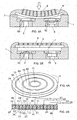
- an electroactive polymer actuator of the first embodiment has a disk-shaped laminate 5, which is formed by alternately placing first to sixth ring members 11 to 16 having different diameters of an electroactive polymer material such as silicon rubber and an acrylic material, and first to seventh ring electrodes 21 to 27 having different diameters in a concentric pattern such that each of the ring members is positioned between inner and outer peripheral surfaces of adjacent ring electrodes.
- the numeral 4 designates a flexible thin sheet as a diaphragm, which is attached to a bottom surface of the laminate 5 .
- the first ring electrode 21 can be obtained by forming a conductive layer on an inner peripheral surface of the first ring member 11, and the second ring electrode 22 can be obtained by forming a conductive layer on an outer peripheral surface of the first ring member 11.
- the conductive layer for example, it is preferred to use a physical vapor deposition such as sputtering.
- the second ring member 12 is placed around the second electrode 22 such that the outer peripheral surface of the first ring member 11 is connected to an inner peripheral surface of the second tubular member 12 through the second ring electrode 22 .
- the third ring electrode 23 can be obtained by forming a conductive layer on an outer peripheral surface of the second ring member 12B .
- the remaining ring electrodes (24-27) and the remaining ring members ( 13-16) are placed according to the same manner to obtain the laminate 5.
- the first ring electrode 21 is positioned between a center cylinder solid 40 and the first ring member 11.
- the electroactive polymer actuator has a voltage applying unit for applying a voltage between odd-numbered ring electrodes and even-numbered ring electrodes in the case of counting the number of the ring electrodes from an innermost ring electrode (i.e., first ring electrode 21 ) of the laminate 5, to thereby cause a deformation in the laminate 5.
- the first, third, fifth and seventh ring electrodes 21, 23, 25, 27
- the second, fourth and sixth ring electrodes 22, 24, 26
- the numeral 32 designates an on-off switch used to apply the voltage between those electrodes.
- the switch 32 when the switch 32 is turned on, a deformation of the laminate 5 happens such that the dimension in the radial direction of the laminate decreases, and the dimension in the axial direction of the laminate increases, as shown in FIG. 1A.
- the flexible thin sheet 4 When the laminate 5 is mounted on the flexible thin sheet 4, the flexible thin sheet 4 can be bent by the deformation force of the laminate, as shown in FIG. 2A. Then, when the switch 32 is turned off, the laminate 5 recovers its original shape, as shown in FIG. 2B. Therefore, by repeating this switch operation, the diaphragm of the flexible thin sheet 4 can be periodically deformed.
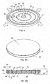
- This diaphragm pump has a casing 1 having a concave 7 for providing a pump chamber in its top surface and intake and exhaust passages ( 2, 3 ) connecting to the concave, and the thin sheet 4 of a flexible material for covering the concave as a diaphragm.
- the laminate 5 of the electroactive polymer actuator is mounted on a surface of the thin sheet that is opposed to the surface facing the concave 7 .
- the thin sheet 4 is made of a metal material, the laminate is connected to the thin sheet through a required insulation layer (not shown):
- the numerals 50 and 52 designate one-way valves built in the intake and exhaust passages ( 2 , 3 ).
- the diaphragm 4 When a voltage is applied to the actuator, the diaphragm 4 is bent by the deformation of the laminate 5 to decrease an internal volume of the pump chamber, as shown in FIG. 3A, so that a fluid such as air is exhausted from the pump chamber through the exhaust passage 3. Then, when the applied voltage is removed, the laminate 5 of the actuator recovers its original shape, as shown in FIG, 3B, so that the fluid comes into the pump chamber through the intake passage 2.
- the conventional electroactive polymer actuator uses, as a diaphragm, a laminate composed of a single sheet member of the electroactive polymer material and a pair of electrode layers formed on both surfaces of the sheet member, it is difficult to obtain a constant diaphragm motion during the pumping operation, as described above.
- the laminate 5 having the concentric arrangement of the plurality of ring members of the electroactive polymer material is used as the diaphragm drive means, it is possible to provide a controlled diaphragm motion at a high response speed.
- expansion and contraction forces of the laminate 5 are equal to a sum of the expansion and contraction forces of the respective ring members (11-16). Therefore, the actuator of this embodiment can provide a more powerful pumping action than the conventional actuator using only the single sheet member of the electroactive polymer material as the diaphragm. Moreover, there is another advantage that a deformation amount of the diaphragm can be controlled with accuracy in response to a magnitude of the voltage applied to the actuator.
- the number of the ring members of the electroactive polymer material is not limited.
- the actuator when using the actuator as the diaphragm drive means for the diaphragm pump, it is recommended to select the number of the ring members within a range of 3 to 10 to achieve the high pumping performance with reliability.
- the number of the ring members is more than 10, there is a case that the size of the actuator is too big for small-size devices.
- the production cost of the actuator may increase.
- the laminate of the electroactive polymer actuator of the present invention can be manufactured by the following method. First, a plurality of tubular members of the electroactive polymer material having different diameters and a plurality of tubular electrodes having different diameters are alternately placed to obtain a solid cylinder body having riumerous concentric layers. Each of the tubular electrodes can be obtained by forming a conductive film on the outer and/or inner peripheral surface of the respective ring members with use of a PVD method such as sputtering. Then, the solid cylinder body is cut (or sliced) in a direction perpendicular to its axial direction to obtain a disk-shaped laminate having a desired axial length. According to this method, it is possible to efficiently manufacture the laminate for the electroactive polymer actuator of the present invention.
- the first to sixth ring members ( 11-16 ) of the electroactive polymer actuator of this embodiment has a same wall thickness.
- a magnitude of voltage (V1) applied between the first and second ring electrodes (21 , 22) spaced by the first ring member 11 is smaller than the magnitude of voltage (V2) applied to the second and third ring electrodes ( 22, 23) spaced by the second ring member 12.
- the magnitude of voltage (V2) applied between the second and third ring electrodes (22, 23) spaced by the second ring member 12 is smaller than the magnitude of voltage (V3) applied to the third and fourth ring electrodes (23, 24 ) spaced by the third ring member 13.
- the magnitudes of the respective voltages applied between the ring electrodes are determined such that an expansion amount in the axial direction of each of the ring members is substantially equal to that of the adjacent ring member. As a result, it is possible to achieve a uniform elongation in the axial direction of the laminate.
- first insulation layers are formed on exposed ends of the even-numbered ring electrodes ( 22, 24, 26 ) on a top surface of the laminate 5
- second insulation layers are formed on exposed ends of the odd-numbered ring electrodes (21, 23, 25, 27) on a bottom surface of the laminate.
- first conductive layers 71, 72, 73, 74 are formed on the top surface of the laminate 5 such that each of the first conductive layers (e.g., 72) is separated from an adjacent first conductive layer (e.g., 73) by the insulation layer (e.g., 64).
- each of the first conductive layers (71-74) is connected to the exposed end of the odd-numbered ring electrodes (21, 23, 25, 27) on the top surface of the laminate 5.
- a single second conductive layer 80 is formed on the entire bottom surface of the laminate 5 such that the exposed ends of the even-numbered ring electrodes (22, 24, 26) are electrically connected to each other by the second conductive layer.
- the second conductive layer 80 is used as an earth electrode.
- a plurality of DC power sources (not shown) can be used.
- a Schenkel circuit may be used. In this case, a plurality of voltages can be obtained by a single power source.
- a laminate of the electroactive polymer actuator is formed such that wall thicknesses ( T1, T2, T3, T4 ) of first to fourth ring members ( 11, 12, 13, 14 ) satisfy the condition of T1 > T2 > T3 > T4 . That is, the wall thickness of each of the first to sixth ring members is determined such that when a constant voltage is applied between the odd-numbered ring electrodes connected to the positive pole and the even-numbered ring electrodes connected to the negative pole of the DC power supply 30 , an expansion amount in the axial direction of each of the ring members is substantially equal to that of the adjacent ring member. As a result, it is possible to achieve a uniform elongation in the axial direction of the laminate.
- first insulation layers ( 61, 63, 65 ) are formed on exposed ends of the odd-numbered ring electrodes ( 21, 23, 25 ) on a top surface of the laminate, and second insulation layers ( 62, 64 ) are formed on exposed ends of the even-numbered ring electrodes (22, 24) on a bottom surface of the laminate 5 .
- a first conductive layer 70 is formed on the entire top surface of the laminate 5 such that the exposed ends of the even-numbered ring electrodes (22, 24) on the top surface of the laminate are electrically connected to each other by the first conductive layer.
- a second conductive layer 80 is formed on the entire bottom surface of the laminate 5 such that the exposed ends of the odd-numbered ring electrodes (21, 23, 25) are electrically connected to each other by the second conductive layer.
- the DC power supply 30 is connected between the first and second conductive layers (70, 80) through the on-off switch 32.
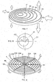
- each of the first to fifth ring members ( 21-25 ) may be formed in a cylinder hollow shape such that a center P2 of the inner circle C2 is displaced from the center P1 of the outer circle C1.
- a deformation of the laminate happens such that the dimension in the radial direction of the laminate decreases, and the dimension in the axial direction of the laminate increases.
- a contraction amount in the radial direction at the side R2 of the laminate is larger than the contraction amount at the side R1 of the laminate.
- an elongation in an axial direction at the side R2 of the laminate is greater than the elongation at the side R1 of the laminate, so that the laminate 5 is bent, as shown by the arrows in FIG. 7.
- ring members of the electroactive polymer actuator may be formed in similar elliptic rings, and placed such that center axes of those ring members are consistent with each other and the each of the ring members is positioned between adjacent ring electrodes.
- an electroactive polymer actuator has an arrangement of a plurality of laminates 5A each having a triangular prism shape.
- Each of the laminates 5A includes a plurality electrodes 20A and electroactive polymer materials 10A, which are alternately placed in a direction of a vertical line extending from a vertex P of a triangle that is a general surface of the triangular prism to a base S of the triangle.
- the number of the laminates is 8.
- Those laminates 5A are arranged as a whole in an octagonal pattern such that the vertex P of the triangle is positioned in the vicinity of a center of the octagonal pattern, and each of the laminates 5A is spaced from an adjacent laminate by a required distance d.
- This actuator also has a voltage applying unit (not shown) for applying a voltage between the electrodes 20A of each of the laminates to cause a deformation in the laminate.
- a diaphragm 4A attached to the arrangement of the laminates 5A can be bent as in the case of the first embodiment, as shown by the arrows in FIG. 9.
- an electroactive polymer actuator of the third embodiment has a spiral structure 5B formed by winding a laminate including an elongated sheet 10B of an electroactive polymer material such as silicon rubber and an acrylic material, a pair of electrode layers (21B, 22B) formed on both surfaces of the elongated sheet, and an insulation layer 60B formed on the electrode layer 22B.
- the insulation layer 60B prevents short circuit between the electrode layers ( 21B, 22B ) in the spiral structure.
- This actuator also has a voltage applying unit for applying a voltage between the electrode layers to cause a deformation in the spiral structure 5B.
- a voltage applying unit for applying a voltage between the electrode layers to cause a deformation in the spiral structure 5B.
- a unimorph type diaphragm drive unit which is characterized in that a single laminate 5 of the electroactive polymer actuator of the present invention is mounted on one surface of the diaphragm 4 .
- a bimorph-type diaphragm drive unit which is characterized in that a pair of laminates 5 of the electroactive polymer actuators of the present invention are mounted on both surfaces of a diaphragm 4 , may be used. In this case, by applying a voltage only to the laminate 5 of the upper actuator, the diaphragm 4 can be bent, as shown in FIG. 11A.
- this bimorph-type diaphragm drive unit can provide an increased range of the diaphragm motion.
Description
- The present invention relates to an electroactive polymer actuator, which is preferably used for devices such as small-sized diaphragm pumps, and a diaphragm pump using the actuator.
- In the past, for devices such as small-sized diaphragm pumps, it has been proposed to use a laminate composed of a sheet of an electroactive polymer material such as silicon rubber and an acrylic material, and a pair of electrode layers formed on both surfaces of the sheet. When a voltage is applied between the electrode layers, a deformation of the laminate happens such that a dimension in the thickness (vertical) direction of the laminate decreases, and the dimension in the horizontal direction of the laminate increases. This phenomenon is known as electroactive effect.
- For example, Japanese Patent Early Publication [kokai] No. 2001-263486 discloses a diaphragm pump using the electroactive effect. That is, as shown in FIG. 11, this diaphragm pump comprises a
casing 1P having a concave 7P for providing a pump chamber in its top surface and intake and exhaust passages (2P, 3P), and adiaphragm 10P for covering this concave. Thediaphragm 10P is of a laminate structure, which is formed with a thin-sheet member 12P of an electroactive polymer material, and a pair ofelectrode layers 11P formed on both surfaces of the thin-sheet member by a physical vapor deposition such as sputtering. - When a voltage is applied between the
electrode layers 11P, a dimension in the thickness direction of thediaphragm 10P decreases and the dimension in the horizontal direction thereof increases. This brings a volume change of the pump chamber that is a space surrounded by the concave 7P and thediaphragm 10P. On the other hand, when the applied voltage is removed, thediaphragm 10P recovers its original shape. Therefore, according to this volume change of the pump chamber, it is possible to suck a fluid such as air into the pump chamber through theintake passage 2P, and then exhaust the air in the pump chamber theexhaust passage 3P. By applying a RF voltage having a required frequency between theelectrode layers 11P, this pumping operation can be repeated. - However, in the case of using this
laminate 10P as the diaphragm, it is difficult to control the deformation of the diaphragm during the pumping operation. Therefore, it still has plenty of room for improvement from the viewpoint of providing a stable and reliable pumping operation. In addition, since the diaphragm is formed by thelaminate 10P including the single thin-sheet member 12P of the electroactive polymer material, there are problems that a deformation force of the diaphragm is relatively small, and a deformation speed thereof is relatively slow. These may lead to reductions in exhaust amount and response speed of the diaphragm pump. Thus, it is said that these problems are causes of preventing the actual use of the devices such as the small-sized diaphragm pump using the electroactive effect. - Another prior art actuator is disclosed in
EP 0534082 . - In view of the above problems, a concern of the present invention is to provide an electroactive polymer actuator, which includes the capability of improving response speed and operation reliability of a device using electroactive effect.
- That is, the electroactive polymer actuator comprises:
- a laminate including a tubular member of an electroactive polymer material, a first electrode formed on an inner peripheral surface of the tubular member, and a second electrode formed on an outer peripheral surface of the tubular member; and
- a voltage applying unit for applying a voltage between the first and second electrodes to cause a deformation in the laminate.
- In addition, it is preferred that the laminate of the electroactive polymer actuator further includes:
- a second tubular member of an electroactive polymer material, which is placed around the second electrode such that the outer peripheral surface of the tubular member is connected to an inner peripheral surface of the second tubular member through the second electrode; and
- a third electrode formed on an outer peripheral surface of the second tubular member;
- Moreover, to achieve further improved response speed and operation reliability of the device using electroactive effect, another concern of the present invention is to provide an electroactive polymer actuator comprising:
- a laminate formed by alternately placing a plurality of ring members of an electroactive polymer material having different diameters and a plurality of ring electrodes having different diameters such that each of the ring members is positioned between inner and outer peripheral surfaces of adjacent ring electrodes; and
- a voltage applying means for applying a voltage(s) between odd-numbered ring electrodes and even-numbered ring electrodes in the case of counting the ring electrodes in order from an innermost ring electrode of the laminate, to thereby cause a deformation in the laminate.
- A further concern of the present invention is to provide an electroactive polymer actuator characterized by a unique arrangement of laminates described below, which includes the capability of improving response speed and operation reliability of a device using electroactive effect. That is, this actuator comprises:
- a plurality of laminates each having a triangular prism shape, each of the laminates including a pair of electrodes and an electroactive polymer member, which are alternately placed in a direction of a vertical line extending from a vertex of a triangle that is a general surface of the triangular prism to a base of the triangle, the laminates being arranged as a whole in a regular polygonal pattern such that the vertex of the triangle is positioned in the vicinity of a center of the polygonal pattern, and each of the laminates is spaced from an adjacent laminate by a required distance; and
- a voltage applying means for applying a voltage between the electrodes spaced from each other by the electroactive polymer material with respect to each of the laminates, to thereby cause a deformation in the laminate.
- Another concern of the present invention is to provide an electroactive polymer actuator characterized by a spiral structure formed by winding an elongated laminate described below, which includes the capability of improving response speed and operation reliability of a device using electroactive effect. That is, this actuator comprises:
- the spiral structure formed by winding a laminate including an elongated sheet of an electroactive polymer material, a pair of first and second electrode layers formed on opposite surfaces of the elongated sheet, and an insulation layer formed on one of the electrode layers; and
- a voltage applying means for applying a voltage between the electrode layers to cause a deformation in the spiral structure.
- In addition, as a particularly preferred application of the electroactive polymer actuator, the present invention provides a diaphragm pump comprising the electroactive polymer actuator of any one of the above-mentioned electroactive polymer actuators as a diaphragm drive means, and a thin sheet of a flexible material as a diaphragm, on a surface of which the laminate of the electroactive polymer actuator is mounted.
- These and still other objects and advantages of the present invention will become apparent from the following detail description of the invention and preferred embodiments of the invention.
-
- FIGS. 1A and 1B are perspective and cross-sectional views of an electroactive polymer actuator according to a first embodiment of the present invention;
- FIGS. 2A and 2B are cross-sectional views illustrating a deformation of the electroactive polymer actuator caused when a voltage is applied;
- FIGS. 3A and 3B are schematic cross-sectional views of a diaphragm pump using the actuator;
- FIGS. 4A and 4B are perspective and cross-sectional views showing an electric circuit of the electroactive polymer actuator;
- FIG. 5 is a perspective view of a laminate of the electroactive polymer actuator according to a first modification of the first embodiment;
- FIGS. 6A and 6B are perspective and cross-sectional views showing an electric circuit of the electroactive polymer actuator of FIG. 5;
- FIG. 7 is a perspective view of a laminate of the electroactive polymer actuator according to a second modification of the first embodiment;
- FIG. 8 is a plan view of a ring member of the laminate of FIG. 7
- FIG. 9 is a perspective view of a laminate of an electroactive polymer actuator according to a second embodiment of the present invention;
- FIG. 10 is a perspective view of a laminate of an electroactive polymer actuator according to a third embodiment of the present invention;
- FIGS. 11A to 11C are schematic views showing operations of a bimorph-type diaphragm drive unit using a pair of the electroactive polymer actuators of the present invention; and
- FIG. 12 is a cross-sectional view of a conventional diaphragm pump.
- Preferred embodiments of the present invention are explained in detail referring to the attached drawings. However, these embodiments do not limit the scope of the present invention.
- As shown in FIGS. 1A and 1B, an electroactive polymer actuator of the first embodiment has a disk-shaped
laminate 5, which is formed by alternately placing first tosixth ring members 11 to 16 having different diameters of an electroactive polymer material such as silicon rubber and an acrylic material, and first toseventh ring electrodes 21 to 27 having different diameters in a concentric pattern such that each of the ring members is positioned between inner and outer peripheral surfaces of adjacent ring electrodes. In FIG. 1A, thenumeral 4 designates a flexible thin sheet as a diaphragm, which is attached to a bottom surface of thelaminate 5. - For example, the
first ring electrode 21 can be obtained by forming a conductive layer on an inner peripheral surface of thefirst ring member 11, and thesecond ring electrode 22 can be obtained by forming a conductive layer on an outer peripheral surface of thefirst ring member 11. To form the conductive layer, for example, it is preferred to use a physical vapor deposition such as sputtering. Then, thesecond ring member 12 is placed around thesecond electrode 22 such that the outer peripheral surface of thefirst ring member 11 is connected to an inner peripheral surface of the secondtubular member 12 through thesecond ring electrode 22. In addition, thethird ring electrode 23 can be obtained by forming a conductive layer on an outer peripheral surface of the second ring member 12B. The remaining ring electrodes (24-27) and the remaining ring members (13-16) are placed according to the same manner to obtain thelaminate 5. In this embodiment, thefirst ring electrode 21 is positioned between a center cylinder solid 40 and thefirst ring member 11. - As shown in FIG. 1B, the electroactive polymer actuator has a voltage applying unit for applying a voltage between odd-numbered ring electrodes and even-numbered ring electrodes in the case of counting the number of the ring electrodes from an innermost ring electrode (i.e., first ring electrode 21) of the
laminate 5, to thereby cause a deformation in thelaminate 5. In this embodiment, the first, third, fifth and seventh ring electrodes (21, 23, 25, 27) are connected to the negative pole of aDC power supply 30, and the second, fourth and sixth ring electrodes (22, 24, 26) are connected to the positive pole of theDC power supply 30. In FIG. 1B, the numeral 32 designates an on-off switch used to apply the voltage between those electrodes. - In the electroactive polymer actuator having the above structure, when the
switch 32 is turned on, a deformation of thelaminate 5 happens such that the dimension in the radial direction of the laminate decreases, and the dimension in the axial direction of the laminate increases, as shown in FIG. 1A. When thelaminate 5 is mounted on the flexiblethin sheet 4, the flexiblethin sheet 4 can be bent by the deformation force of the laminate, as shown in FIG. 2A. Then, when theswitch 32 is turned off, thelaminate 5 recovers its original shape, as shown in FIG. 2B. Therefore, by repeating this switch operation, the diaphragm of the flexiblethin sheet 4 can be periodically deformed. - As an example, in FIGS. 3A and 3B, a diaphragm pump using the electroactive polymer actuator of the present invention is explained. This diaphragm pump has a
casing 1 having a concave 7 for providing a pump chamber in its top surface and intake and exhaust passages (2, 3) connecting to the concave, and thethin sheet 4 of a flexible material for covering the concave as a diaphragm. Thelaminate 5 of the electroactive polymer actuator is mounted on a surface of the thin sheet that is opposed to the surface facing the concave 7. When thethin sheet 4 is made of a metal material, the laminate is connected to the thin sheet through a required insulation layer (not shown): Thenumerals - When a voltage is applied to the actuator, the
diaphragm 4 is bent by the deformation of thelaminate 5 to decrease an internal volume of the pump chamber, as shown in FIG. 3A, so that a fluid such as air is exhausted from the pump chamber through theexhaust passage 3. Then, when the applied voltage is removed, thelaminate 5 of the actuator recovers its original shape, as shown in FIG, 3B, so that the fluid comes into the pump chamber through theintake passage 2. - According to the above diaphragm pump of the present invention, it is possible to provide a stable pumping operation at an improved response speed. That is, since the conventional electroactive polymer actuator uses, as a diaphragm, a laminate composed of a single sheet member of the electroactive polymer material and a pair of electrode layers formed on both surfaces of the sheet member, it is difficult to obtain a constant diaphragm motion during the pumping operation, as described above. However; in the present invention, since the
laminate 5 having the concentric arrangement of the plurality of ring members of the electroactive polymer material is used as the diaphragm drive means, it is possible to provide a controlled diaphragm motion at a high response speed. - In addition, expansion and contraction forces of the
laminate 5 are equal to a sum of the expansion and contraction forces of the respective ring members (11-16). Therefore, the actuator of this embodiment can provide a more powerful pumping action than the conventional actuator using only the single sheet member of the electroactive polymer material as the diaphragm. Moreover, there is another advantage that a deformation amount of the diaphragm can be controlled with accuracy in response to a magnitude of the voltage applied to the actuator. - In the actuator of the present invention, the number of the ring members of the electroactive polymer material is not limited. However, when using the actuator as the diaphragm drive means for the diaphragm pump, it is recommended to select the number of the ring members within a range of 3 to 10 to achieve the high pumping performance with reliability. When the number of the ring members is more than 10, there is a case that the size of the actuator is too big for small-size devices. In addition, the production cost of the actuator may increase.
- As an example, the laminate of the electroactive polymer actuator of the present invention can be manufactured by the following method. First, a plurality of tubular members of the electroactive polymer material having different diameters and a plurality of tubular electrodes having different diameters are alternately placed to obtain a solid cylinder body having riumerous concentric layers. Each of the tubular electrodes can be obtained by forming a conductive film on the outer and/or inner peripheral surface of the respective ring members with use of a PVD method such as sputtering. Then, the solid cylinder body is cut (or sliced) in a direction perpendicular to its axial direction to obtain a disk-shaped laminate having a desired axial length. According to this method, it is possible to efficiently manufacture the laminate for the electroactive polymer actuator of the present invention.
- By the way, as shown in FIG. 1A, the first to sixth ring members (11-16) of the electroactive polymer actuator of this embodiment has a same wall thickness. In this case; it is preferred to apply a plurality of different voltages (V1, V2, V3, V4) between the odd-numbered ring electrodes (21, 23, 25, 27) connected to the positive pole and the even-numbered ring electrodes (22, 24, 26) connected to the negative pole of the DC power supply according to the following manner.
- That is, a magnitude of voltage (V1) applied between the first and second ring electrodes (21, 22) spaced by the
first ring member 11 is smaller than the magnitude of voltage (V2) applied to the second and third ring electrodes (22, 23) spaced by thesecond ring member 12. Similarly, the magnitude of voltage (V2) applied between the second and third ring electrodes (22, 23) spaced by thesecond ring member 12 is smaller than the magnitude of voltage (V3) applied to the third and fourth ring electrodes (23, 24) spaced by thethird ring member 13. The magnitudes of the respective voltages applied between the ring electrodes are determined such that an expansion amount in the axial direction of each of the ring members is substantially equal to that of the adjacent ring member. As a result, it is possible to achieve a uniform elongation in the axial direction of the laminate. - As described above, in the case of applying the different voltages between the odd-numbered ring electrodes and the even-numbered ring electrodes of the laminate, it is preferred to form an electric circuit, as shown in FIGS. 4A and 4B. That is, first insulation layers (62, 64, 66) are formed on exposed ends of the even-numbered ring electrodes (22, 24, 26) on a top surface of the
laminate 5, and second insulation layers (61, 63, 65, 67) are formed on exposed ends of the odd-numbered ring electrodes (21, 23, 25, 27) on a bottom surface of the laminate. - Then, a plurality of first conductive layers (71, 72, 73, 74) are formed on the top surface of the
laminate 5 such that each of the first conductive layers (e.g., 72) is separated from an adjacent first conductive layer (e.g., 73) by the insulation layer (e.g., 64). As a result, each of the first conductive layers (71-74) is connected to the exposed end of the odd-numbered ring electrodes (21, 23, 25, 27) on the top surface of thelaminate 5. On the other hand, a single secondconductive layer 80 is formed on the entire bottom surface of thelaminate 5 such that the exposed ends of the even-numbered ring electrodes (22, 24, 26) are electrically connected to each other by the second conductive layer. The secondconductive layer 80 is used as an earth electrode. To apply the required voltages (V1, V2, V3, V4) between the first conductive layers (71 -74) and theearth electrode 80, a plurality of DC power sources (not shown) can be used. Alternatively, a Schenkel circuit may be used. In this case, a plurality of voltages can be obtained by a single power source. - Next, modifications of the electroactive polymer actuator of this embodiment are explained.
- As a first modification, as shown in FIG. 5, it is preferred that a laminate of the electroactive polymer actuator is formed such that wall thicknesses (T1, T2, T3, T4) of first to fourth ring members (11, 12, 13, 14) satisfy the condition of T1>T2>T3>T4. That is, the wall thickness of each of the first to sixth ring members is determined such that when a constant voltage is applied between the odd-numbered ring electrodes connected to the positive pole and the even-numbered ring electrodes connected to the negative pole of the
DC power supply 30, an expansion amount in the axial direction of each of the ring members is substantially equal to that of the adjacent ring member. As a result, it is possible to achieve a uniform elongation in the axial direction of the laminate. - When applying the constant voltage between the odd-numbered ring electrodes (21, 23, 25) and the even-numbered ring electrodes (22, 24) of the
laminate 5, it is preferred to form an electric circuit, as shown in FIGS. 6A and 6B. That is, first insulation layers (61, 63, 65) are formed on exposed ends of the odd-numbered ring electrodes (21, 23, 25) on a top surface of the laminate, and second insulation layers (62, 64) are formed on exposed ends of the even-numbered ring electrodes (22, 24) on a bottom surface of thelaminate 5. - Then, a first
conductive layer 70 is formed on the entire top surface of thelaminate 5 such that the exposed ends of the even-numbered ring electrodes (22, 24) on the top surface of the laminate are electrically connected to each other by the first conductive layer. Similarly, a secondconductive layer 80 is formed on the entire bottom surface of thelaminate 5 such that the exposed ends of the odd-numbered ring electrodes (21, 23, 25) are electrically connected to each other by the second conductive layer. Finally, theDC power supply 30 is connected between the first and second conductive layers (70, 80) through the on-off switch 32. - As a second modification, as shown in FIGS. 7 and 8, each of the first to fifth ring members (21-25) may be formed in a cylinder hollow shape such that a center P2 of the inner circle C2 is displaced from the center P1 of the outer circle C1. When a voltage is applied to this
laminate 5, a deformation of the laminate happens such that the dimension in the radial direction of the laminate decreases, and the dimension in the axial direction of the laminate increases. In this case, a contraction amount in the radial direction at the side R2 of the laminate is larger than the contraction amount at the side R1 of the laminate. In other words, an elongation in an axial direction at the side R2 of the laminate is greater than the elongation at the side R1 of the laminate, so that thelaminate 5 is bent, as shown by the arrows in FIG. 7. - In addition, as a third modification, ring members of the electroactive polymer actuator may be formed in similar elliptic rings, and placed such that center axes of those ring members are consistent with each other and the each of the ring members is positioned between adjacent ring electrodes.
- As shown in FIG. 9, an electroactive polymer actuator according to the second embodiment of the present invention has an arrangement of a plurality of
laminates 5A each having a triangular prism shape. Each of thelaminates 5A includes aplurality electrodes 20A andelectroactive polymer materials 10A, which are alternately placed in a direction of a vertical line extending from a vertex P of a triangle that is a general surface of the triangular prism to a base S of the triangle. In this embodiment, the number of the laminates is 8. - Those
laminates 5A are arranged as a whole in an octagonal pattern such that the vertex P of the triangle is positioned in the vicinity of a center of the octagonal pattern, and each of thelaminates 5A is spaced from an adjacent laminate by a required distance d. This actuator also has a voltage applying unit (not shown) for applying a voltage between theelectrodes 20A of each of the laminates to cause a deformation in the laminate. By simultaneously applying the voltages to all of the laminates, adiaphragm 4A attached to the arrangement of thelaminates 5A can be bent as in the case of the first embodiment, as shown by the arrows in FIG. 9. - As shown in FIG. 10, an electroactive polymer actuator of the third embodiment has a
spiral structure 5B formed by winding a laminate including anelongated sheet 10B of an electroactive polymer material such as silicon rubber and an acrylic material, a pair of electrode layers (21B, 22B) formed on both surfaces of the elongated sheet, and aninsulation layer 60B formed on theelectrode layer 22B. Theinsulation layer 60B prevents short circuit between the electrode layers (21B, 22B) in the spiral structure. - This actuator also has a voltage applying unit for applying a voltage between the electrode layers to cause a deformation in the
spiral structure 5B. By applying the voltage between the electrode layers (21B, 22B) of thespiral structure 5B, adiaphragm 4B attached to thespiral structure 5B can be bent as in the case of the first embodiment, as shown by the arrows in FIG. 10. - In the above first to third embodiments, a unimorph type diaphragm drive unit, which is characterized in that a
single laminate 5 of the electroactive polymer actuator of the present invention is mounted on one surface of thediaphragm 4, was introduced. However, as shown in FIGS. 11A to 11C, a bimorph-type diaphragm drive unit, which is characterized in that a pair oflaminates 5 of the electroactive polymer actuators of the present invention are mounted on both surfaces of adiaphragm 4, may be used. In this case, by applying a voltage only to thelaminate 5 of the upper actuator, thediaphragm 4 can be bent, as shown in FIG. 11A. In addition, by applying a voltage only to thelaminate 5 of the lower actuator, thediaphragm 4 can be bent, as shown in FIG. 11C. Therefore, this bimorph-type diaphragm drive unit can provide an increased range of the diaphragm motion.
Claims (6)
- A diaphragm pump comprising:an electroactive polymer actuator as a diaphragm drive means, which comprises a laminate (5) including a tubular member (11) of an electroactive polymer material, a first electrode (21) formed on an inner peripheral surface of said tubular member, and a second electrode (22) formed on an outer peripheral surface of said tubular member, and a voltage applying means (30, 32) for applying a voltage between said first and second electrodes to cause a deformation in said laminate; and characterized bya thin sheet (4) of a flexible material as a diaphragm, on a surface of which said laminate (5) of the electroactive polymer actuator is mounted.
- The diaphragm pump as set forth in claim 1, wherein said laminate further includes:a second tubular member (12) of an electroactive polymer material, which is placed around said second electrode such that the outer peripheral surface of said tubular member (11) is connected to an inner peripheral surface of said second tubular member through said second electrode; anda third electrode (23) formed on an outer peripheral surface of said second tubular member ;wherein said voltage applying means applies the voltage(s) between said first and second electrodes and between said second and third electrodes to cause the deformation in said laminate.
- The diaphragm pump as set forth in claim 2, wherein said tubular member and said second tubular member are of hollow cylinder shapes having different diameters, which are concentrically arranged to obtain said laminate.
- The diaphragm pump as set forth in claim 2, wherein each of said tubular member and said second tubular member is formed in a hollow cylinder shape having a center of its outer circle displaced from the center of its inner circle.
- The diaphragm pump as set forth in any one of claims 1 to 4, wherein a pair of the electroactive polymer actuators are used as the diaphragm drive means, and said laminates (5) of the electroactive polymer actuators are mounted on opposite surfaces of said thin sheet (4).
- The diaphragm pump as set forth in any one of the claims 1 to 4, further comprising a casing (1) having a concave (7) for providing a pump chamber, whereas said thin sheet (4) is covering the concave (7).
Applications Claiming Priority (2)
| Application Number | Priority Date | Filing Date | Title |
|---|---|---|---|
| JP2001392700A JP3832338B2 (en) | 2001-12-25 | 2001-12-25 | Electrostrictive polymer actuator |
| EP20020025416 EP1323925B1 (en) | 2001-12-25 | 2002-11-14 | Electroactive polymer actuator and diaphragm pump using the same |
Related Parent Applications (1)
| Application Number | Title | Priority Date | Filing Date |
|---|---|---|---|
| EP20020025416 Division EP1323925B1 (en) | 2001-12-25 | 2002-11-14 | Electroactive polymer actuator and diaphragm pump using the same |
Publications (3)
| Publication Number | Publication Date |
|---|---|
| EP1683968A2 EP1683968A2 (en) | 2006-07-26 |
| EP1683968A3 EP1683968A3 (en) | 2006-08-16 |
| EP1683968B1 true EP1683968B1 (en) | 2007-08-01 |
Family
ID=19188676
Family Applications (2)
| Application Number | Title | Priority Date | Filing Date |
|---|---|---|---|
| EP20060005400 Expired - Fee Related EP1683968B1 (en) | 2001-12-25 | 2002-11-14 | Electroactive polymer actuator and diaphragm pump using the same |
| EP20020025416 Expired - Fee Related EP1323925B1 (en) | 2001-12-25 | 2002-11-14 | Electroactive polymer actuator and diaphragm pump using the same |
Family Applications After (1)
| Application Number | Title | Priority Date | Filing Date |
|---|---|---|---|
| EP20020025416 Expired - Fee Related EP1323925B1 (en) | 2001-12-25 | 2002-11-14 | Electroactive polymer actuator and diaphragm pump using the same |
Country Status (8)
| Country | Link |
|---|---|
| US (1) | US6960864B2 (en) |
| EP (2) | EP1683968B1 (en) |
| JP (1) | JP3832338B2 (en) |
| KR (1) | KR100510224B1 (en) |
| CN (3) | CN1901350A (en) |
| DE (2) | DE60210736T2 (en) |
| HK (1) | HK1054420B (en) |
| SG (1) | SG103368A1 (en) |
Families Citing this family (71)
| Publication number | Priority date | Publication date | Assignee | Title |
|---|---|---|---|---|
| WO2004037152A2 (en) * | 2002-10-07 | 2004-05-06 | Pavad Medical, Inc. | Vascular assist device and methods |
| US20040230090A1 (en) * | 2002-10-07 | 2004-11-18 | Hegde Anant V. | Vascular assist device and methods |
| US20050113892A1 (en) * | 2003-11-26 | 2005-05-26 | Sproul Michael E. | Surgical tool with an electroactive polymer for use in a body |
| AU2005280005A1 (en) * | 2004-08-25 | 2006-03-09 | Pavad Medical, Inc. | Artificial sphincter |
| JP2006090189A (en) * | 2004-09-22 | 2006-04-06 | Omron Healthcare Co Ltd | Air pump, pump system, electronic sphygmomanometer and massaging machine |
| US7544260B2 (en) * | 2004-10-20 | 2009-06-09 | Mark Banister | Micro thruster, micro thruster array and polymer gas generator |
| JP2006154390A (en) * | 2004-11-30 | 2006-06-15 | Seiko Precision Inc | Lens driving device, and imaging apparatus |
| AU2005317188B2 (en) * | 2004-12-14 | 2011-06-09 | Mark Banister | Actuator pump system |
| EP1841966B1 (en) * | 2005-01-26 | 2010-04-28 | Panasonic Electric Works Co., Ltd. | Piezoelectric-driven diaphragm pump |
| KR100617616B1 (en) | 2005-04-08 | 2006-09-01 | 한국생산기술연구원 | Method for manufacturing a multi-layer polymer actuator equipped with nano-scale thin-film dielectric elastomers |
| KR100664395B1 (en) | 2005-04-08 | 2007-01-03 | 한국생산기술연구원 | Polymer actuator capable of fine control of contractive displacement, and control method thereof |
| US7352111B2 (en) * | 2005-12-01 | 2008-04-01 | Schlumberger Technology Corporation | Electroactive polymer pumping system |
| KR20080077374A (en) * | 2005-12-20 | 2008-08-22 | 코닌클리케 필립스 일렉트로닉스 엔.브이. | Blended sensor system and method |
| WO2007072411A1 (en) * | 2005-12-20 | 2007-06-28 | Koninklijke Philips Electronics N.V. | Camera diaphragm and lens positioning system employing a dielectrical polymer actuator |
| DE102005062479A1 (en) * | 2005-12-27 | 2007-07-05 | BSH Bosch und Siemens Hausgeräte GmbH | Dosing arrangement for adding an additive into a chamber of a household appliance comprises actuators formed as electro-active polymers for driving conveyor units |
| KR100791378B1 (en) | 2005-12-29 | 2008-01-07 | 삼성전자주식회사 | User command input apparatus supporting variable input modes, and device using the input apparatus |
| DE102006015493B4 (en) * | 2006-04-03 | 2010-12-23 | Atlas Elektronik Gmbh | Electroacoustic transducer |
| US7951186B2 (en) * | 2006-04-25 | 2011-05-31 | Boston Scientific Scimed, Inc. | Embedded electroactive polymer structures for use in medical devices |
| US10208158B2 (en) | 2006-07-10 | 2019-02-19 | Medipacs, Inc. | Super elastic epoxy hydrogel |
| US20080122589A1 (en) * | 2006-11-28 | 2008-05-29 | Ivanov Yuri A | Tactile Output Device |
| WO2008111397A1 (en) * | 2007-03-12 | 2008-09-18 | Murata Manufacturing Co., Ltd. | Fluid transportation device |
| JP2008251833A (en) * | 2007-03-30 | 2008-10-16 | Tokai Rubber Ind Ltd | Actuator, and actuator convergence object |
| US7719167B2 (en) * | 2007-05-14 | 2010-05-18 | Samsung Electronics Co., Ltd. | Electroactive polymer actuator and manufacturing method thereof |
| KR20100053536A (en) | 2007-06-29 | 2010-05-20 | 아트피셜 머슬, 인코퍼레이션 | Electroactive polymer transducers for sensory feedback applications |
| GB2452047A (en) * | 2007-08-21 | 2009-02-25 | Joseph Anthony Griffiths | Diaphragm for use in a fluid pump comprising a disc of resilient material whose curvature is formed from a plurality of steps |
| FR2920591B1 (en) * | 2007-09-04 | 2009-12-18 | Renault Sas | ELECTROACTIVE MEMBRANE ACTUATOR DEVICE |
| US9995295B2 (en) | 2007-12-03 | 2018-06-12 | Medipacs, Inc. | Fluid metering device |
| DE102008006832A1 (en) * | 2008-01-30 | 2009-08-13 | Eads Deutschland Gmbh | Electromagnetic membrane microactuator |
| JP5209539B2 (en) * | 2008-03-25 | 2013-06-12 | 東海ゴム工業株式会社 | Mechanical impedance adjuster |
| EP2282789B1 (en) | 2008-03-26 | 2015-09-09 | Heart Biotech Limited | Heart assist device |
| US20090259093A1 (en) * | 2008-04-14 | 2009-10-15 | Bhat Nikhil D | Artificial sphincter with piezoelectric actuator |
| EP2294317B1 (en) | 2008-04-30 | 2013-04-17 | Danfoss Polypower A/S | A pump powered by a polymer transducer |
| CN101814577B (en) * | 2009-02-24 | 2013-06-05 | 清华大学 | Electrostrictive material and preparation method thereof as well as electrothermal type actuator |
| GR20090100384A (en) * | 2009-07-08 | 2011-02-18 | Αχιλλεας Τσουκαλης | Insulin pump |
| US9238102B2 (en) | 2009-09-10 | 2016-01-19 | Medipacs, Inc. | Low profile actuator and improved method of caregiver controlled administration of therapeutics |
| KR101113897B1 (en) | 2009-12-07 | 2012-02-29 | 한국과학기술원 | Solenoid System Using Spiral Transparant Material of Conductivity, Apparatus Providing Passive Haptic Feedback Using the Same, Touchpad Using the Same and Control Method |
| JP5733964B2 (en) * | 2009-12-24 | 2015-06-10 | キヤノン株式会社 | Polymer actuator |
| US9500186B2 (en) | 2010-02-01 | 2016-11-22 | Medipacs, Inc. | High surface area polymer actuator with gas mitigating components |
| KR101229211B1 (en) * | 2010-04-21 | 2013-02-01 | 성균관대학교산학협력단 | Fluid jet propulsion system |
| DE102011075127B4 (en) | 2010-05-04 | 2014-10-30 | Electronics And Telecommunications Research Institute | Microvalve structure with a polymer actuator and Lab-on-a-chip module |
| CA2828809A1 (en) | 2011-03-01 | 2012-09-07 | Francois EGRON | Automated manufacturing processes for producing deformable polymer devices and films |
| CN102261325A (en) * | 2011-06-21 | 2011-11-30 | 南京航空航天大学 | Logarithmic solenoid valve pressure-free electric pump |
| CN102330663A (en) * | 2011-06-21 | 2012-01-25 | 无锡长辉机电科技有限公司 | Hyperbolic spiral flow pipe valveless piezoelectric pump |
| CN102330662A (en) * | 2011-06-21 | 2012-01-25 | 无锡长辉机电科技有限公司 | Fermat spiral flow pipe valveless piezoelectric pump |
| DE102011080128A1 (en) * | 2011-07-29 | 2013-01-31 | Robert Bosch Gmbh | Process for producing bendable EAP generators |
| JP5541419B2 (en) | 2011-08-24 | 2014-07-09 | 株式会社村田製作所 | Actuator element and method of manufacturing the actuator element |
| JP5742944B2 (en) * | 2011-08-24 | 2015-07-01 | 株式会社村田製作所 | Actuator element and method of manufacturing the actuator element |
| US8692442B2 (en) | 2012-02-14 | 2014-04-08 | Danfoss Polypower A/S | Polymer transducer and a connector for a transducer |
| US8891222B2 (en) | 2012-02-14 | 2014-11-18 | Danfoss A/S | Capacitive transducer and a method for manufacturing a transducer |
| EP2847249A4 (en) | 2012-03-14 | 2016-12-28 | Medipacs Inc | Smart polymer materials with excess reactive molecules |
| EP2828901B1 (en) | 2012-03-21 | 2017-01-04 | Parker Hannifin Corporation | Roll-to-roll manufacturing processes for producing self-healing electroactive polymer devices |
| WO2013192143A1 (en) | 2012-06-18 | 2013-12-27 | Bayer Intellectual Property Gmbh | Stretch frame for stretching process |
| US9590193B2 (en) | 2012-10-24 | 2017-03-07 | Parker-Hannifin Corporation | Polymer diode |
| US10105504B2 (en) * | 2012-12-18 | 2018-10-23 | Koninklijke Philips N.V. | EAP-driven air pump for patient interfaces |
| US20160025429A1 (en) * | 2013-03-15 | 2016-01-28 | Parker-Hannifin Corporation | Electroactive polymer actuated air flow thermal management module |
| GB2516845A (en) * | 2013-07-31 | 2015-02-11 | Ingegneria Ceramica S R L | An Improved Actuator and Method of Driving Thereof |
| US9166242B2 (en) * | 2013-08-13 | 2015-10-20 | The United States Of America, As Represented By The Secretary Of The Navy | Multi-modal energy harvester |
| US10125758B2 (en) * | 2013-08-30 | 2018-11-13 | Novasentis, Inc. | Electromechanical polymer pumps |
| DE102014205117A1 (en) * | 2014-03-19 | 2015-09-24 | Gemü Gebr. Müller Apparatebau Gmbh & Co. Kommanditgesellschaft | Membrane and process for its production |
| US10744295B2 (en) * | 2015-01-13 | 2020-08-18 | ResMed Pty Ltd | Respiratory therapy apparatus |
| US10119532B2 (en) | 2015-02-16 | 2018-11-06 | Hamilton Sundstrand Corporation | System and method for cooling electrical components using an electroactive polymer actuator |
| WO2017094520A1 (en) | 2015-12-02 | 2017-06-08 | 株式会社村田製作所 | Piezoelectric element, piezoelectric microphone, piezoelectric resonator and method for manufacturing piezoelectric element |
| DE102016004673B4 (en) | 2016-04-18 | 2020-01-02 | Kastriot Merlaku | Drive system for a freely rotatable camera |
| EP3278728A1 (en) * | 2016-08-01 | 2018-02-07 | Nokia Technologies Oy | An apparatus, system and method for detecting analytes from a user's skin |
| EP3282494B1 (en) | 2016-08-11 | 2020-07-22 | Postech Academy-Industry Foundation | Electroactive actuator, mechanical device including the same, and polymer electrolyte |
| US11148048B2 (en) * | 2017-03-07 | 2021-10-19 | Sony Corporation | Content presentation system, content presentation device, and wind presenting device |
| CN109011132B (en) * | 2018-08-28 | 2022-03-22 | 京东方科技集团股份有限公司 | Microneedle system drive structure and microneedle system |
| CN109372729A (en) * | 2018-11-29 | 2019-02-22 | 西安理工大学 | A kind of software pump based on dielectric elastomer driving |
| KR20220020836A (en) * | 2019-06-18 | 2022-02-21 | 스토로브 가부시키가이샤 | electrostatic actuator |
| DE102020117221A1 (en) * | 2020-06-30 | 2021-12-30 | Fresenius Medical Care Deutschland Gmbh | Pump with electroactive polymers and reset element |
| DE102020211553A1 (en) * | 2020-09-15 | 2022-03-17 | B.Braun Avitum Ag | Medical Fluid Pump System |
Family Cites Families (38)
| Publication number | Priority date | Publication date | Assignee | Title |
|---|---|---|---|---|
| US3215078A (en) * | 1964-08-31 | 1965-11-02 | Charles L Stec | Controlled volume piezoelectric pumps |
| US3314103A (en) * | 1965-07-01 | 1967-04-18 | Schluderberg Kurdle Co Inc | Method of electrically stunning animals |
| US3598506A (en) * | 1969-04-23 | 1971-08-10 | Physics Int Co | Electrostrictive actuator |
| US3781955A (en) * | 1970-12-21 | 1974-01-01 | V Lavrinenko | Method of making a piezoelectric element |
| US3858065A (en) * | 1970-12-31 | 1974-12-31 | Becton Dickinson Co | Annular 3m class piezoelectric crystal transducer |
| US3805097A (en) * | 1972-08-07 | 1974-04-16 | B Kravtsov | Piezoelectric accelerometer |
| US4398116A (en) * | 1981-04-30 | 1983-08-09 | Siemens Gammasonics, Inc. | Transducer for electronic focal scanning in an ultrasound imaging device |
| US4435667A (en) * | 1982-04-28 | 1984-03-06 | Peizo Electric Products, Inc. | Spiral piezoelectric rotary actuator |
| JPS6211910A (en) * | 1985-07-01 | 1987-01-20 | Hitachi Electronics Eng Co Ltd | Position controller |
| JPS63242183A (en) * | 1987-03-27 | 1988-10-07 | Hitachi Maxell Ltd | Cylindrical ultrasonic quadrupole motor |
| JPS6455081A (en) * | 1987-08-20 | 1989-03-02 | Komatsu Mfg Co Ltd | Piezo-electric motor |
| JP2690907B2 (en) * | 1987-09-25 | 1997-12-17 | 株式会社日立製作所 | Composite piezoelectric motor |
| DE3839057A1 (en) * | 1988-11-18 | 1990-05-23 | Fraunhofer Ges Forschung | Array-type probe |
| JPH0722578B2 (en) * | 1988-12-09 | 1995-03-15 | 松下電器産業株式会社 | Ultrasonic probe |
| JPH03270943A (en) * | 1990-03-20 | 1991-12-03 | Fujitsu Ltd | Laminated type piezoelectric actuator |
| US5210455A (en) * | 1990-07-26 | 1993-05-11 | Ngk Insulators, Ltd. | Piezoelectric/electrostrictive actuator having ceramic substrate having recess defining thin-walled portion |
| US5262696A (en) * | 1991-07-05 | 1993-11-16 | Rockwell International Corporation | Biaxial transducer |
| DE4127860A1 (en) | 1991-08-22 | 1993-02-25 | Deutsche Aerospace | PUMP SYSTEM FOR CONVEYING LIQUID OR GASEOUS MEDIA |
| JP3218702B2 (en) * | 1992-06-22 | 2001-10-15 | 株式会社村田製作所 | Vibrating gyro |
| US5460181A (en) * | 1994-10-06 | 1995-10-24 | Hewlett Packard Co. | Ultrasonic transducer for three dimensional imaging |
| DE4333871C2 (en) * | 1993-10-05 | 1997-02-20 | Daimler Benz Aerospace Ag | Electro-hydraulic actuator |
| US5559387A (en) * | 1994-05-13 | 1996-09-24 | Beurrier; Henry R. | Piezoelectric actuators |
| US5825386A (en) * | 1995-03-09 | 1998-10-20 | Brother Kogyo Kabushiki Kaisha | Piezoelectric ink-jet device and process for manufacturing the same |
| JP3267151B2 (en) * | 1996-04-12 | 2002-03-18 | ミノルタ株式会社 | Piezoelectric vibrating member and method of manufacturing the same |
| RU2161364C2 (en) * | 1996-06-05 | 2000-12-27 | Окатов Юрий Владимирович | Piezoelectric stepping motor |
| US5961298A (en) * | 1996-06-25 | 1999-10-05 | California Institute Of Technology | Traveling wave pump employing electroactive actuators |
| GB9618052D0 (en) | 1996-08-29 | 1996-10-09 | Univ Birmingham | Piezoelectric elements and devices incorporating same |
| US6891317B2 (en) * | 2001-05-22 | 2005-05-10 | Sri International | Rolled electroactive polymers |
| GB9713872D0 (en) * | 1997-07-02 | 1997-09-03 | Xaar Ltd | Droplet deposition apparatus |
| AUPP307398A0 (en) | 1998-04-21 | 1998-05-14 | Mitchell, William Richard | Fluid pump and actuating system incorporating piezoceramic elements |
| JP3206551B2 (en) * | 1998-06-12 | 2001-09-10 | 株式会社村田製作所 | Vibrator and vibrating gyroscope using it |
| US6362559B1 (en) * | 1999-02-12 | 2002-03-26 | Face International Corp. | Piezoelectric transformer with segmented electrodes |
| DE19938239B4 (en) | 1999-08-12 | 2004-11-25 | Hirschmann, Karl-Heinz, Prof.Dr. | Micropump for conveying, dosing and placing liquids |
| US6362946B1 (en) | 1999-11-02 | 2002-03-26 | Varian Semiconductor Equipment Associates, Inc. | Electrostatic wafer clamp having electrostatic seal for retaining gas |
| JP3893841B2 (en) | 2000-03-22 | 2007-03-14 | 松下電工株式会社 | Diaphragm, diaphragm pump, and method for manufacturing diaphragm |
| US6411014B1 (en) * | 2000-05-09 | 2002-06-25 | Measurement Specialties, Inc. | Cylindrical transducer apparatus |
| US6439556B1 (en) * | 2001-02-15 | 2002-08-27 | Delphi Technologies, Inc. | Active decoupler hydraulic mount |
| SG103371A1 (en) * | 2001-12-28 | 2004-04-29 | Matsushita Electric Works Ltd | Wearable human motion applicator |
-
2001
- 2001-12-25 JP JP2001392700A patent/JP3832338B2/en not_active Expired - Fee Related
-
2002
- 2002-11-05 US US10/287,500 patent/US6960864B2/en not_active Expired - Fee Related
- 2002-11-06 SG SG200206681A patent/SG103368A1/en unknown
- 2002-11-09 KR KR10-2002-0069404A patent/KR100510224B1/en not_active IP Right Cessation
- 2002-11-14 EP EP20060005400 patent/EP1683968B1/en not_active Expired - Fee Related
- 2002-11-14 EP EP20020025416 patent/EP1323925B1/en not_active Expired - Fee Related
- 2002-11-14 DE DE2002610736 patent/DE60210736T2/en not_active Expired - Lifetime
- 2002-11-14 DE DE2002621586 patent/DE60221586T2/en not_active Expired - Lifetime
- 2002-11-18 CN CNA2006101086927A patent/CN1901350A/en active Pending
- 2002-11-18 CN CN2006101086931A patent/CN1901351B/en not_active Expired - Fee Related
- 2002-11-18 CN CNB021506701A patent/CN1272899C/en not_active Expired - Fee Related
-
2003
- 2003-09-20 HK HK03106758.6A patent/HK1054420B/en not_active IP Right Cessation
Non-Patent Citations (1)
| Title |
|---|
| None * |
Also Published As
| Publication number | Publication date |
|---|---|
| EP1683968A3 (en) | 2006-08-16 |
| HK1054420B (en) | 2006-08-18 |
| KR20030055104A (en) | 2003-07-02 |
| EP1323925A3 (en) | 2004-07-07 |
| DE60221586T2 (en) | 2008-04-17 |
| US6960864B2 (en) | 2005-11-01 |
| DE60210736D1 (en) | 2006-05-24 |
| EP1323925B1 (en) | 2006-04-19 |
| CN1901350A (en) | 2007-01-24 |
| HK1054420A1 (en) | 2003-11-28 |
| CN1428926A (en) | 2003-07-09 |
| DE60210736T2 (en) | 2007-03-29 |
| JP3832338B2 (en) | 2006-10-11 |
| JP2003199365A (en) | 2003-07-11 |
| CN1272899C (en) | 2006-08-30 |
| CN1901351B (en) | 2010-09-29 |
| EP1323925A2 (en) | 2003-07-02 |
| DE60221586D1 (en) | 2007-09-13 |
| SG103368A1 (en) | 2004-04-29 |
| KR100510224B1 (en) | 2005-08-30 |
| EP1683968A2 (en) | 2006-07-26 |
| CN1901351A (en) | 2007-01-24 |
| US20030117044A1 (en) | 2003-06-26 |
Similar Documents
| Publication | Publication Date | Title |
|---|---|---|
| EP1683968B1 (en) | Electroactive polymer actuator and diaphragm pump using the same | |
| EP1848046B1 (en) | Transducers of electroactive polymers | |
| US6583533B2 (en) | Electroactive polymer electrodes | |
| US7911115B2 (en) | Monolithic electroactive polymers | |
| US6940211B2 (en) | Electroactive polymers transducers and actuators | |
| US6543110B1 (en) | Electroactive polymer fabrication | |
| US8508109B2 (en) | Electroactive polymer manufacturing | |
| US20010026165A1 (en) | Monolithic electroactive polymers | |
| JP2008527234A (en) | Method and apparatus for exhausting energy during pump operation | |
| EP1540807A1 (en) | An elastomer actuator and a method of making an actuator | |
| EP1482571A3 (en) | Cell driving type piezoelectric/electrostrictive actuator and method of manufacturing the same | |
| EP3987584A1 (en) | Piezoelectric actuator and microfluidic device | |
| EP1994574A1 (en) | Heat efficient micromotor | |
| JP4063301B2 (en) | Method for manufacturing electrostrictive polymer actuator | |
| WO2007043976A1 (en) | Electro-active valveless pump | |
| US6604915B1 (en) | Compact, high efficiency, smart material actuated hydraulic pump | |
| JP4063300B2 (en) | Electrostrictive polymer actuator | |
| US20070140875A1 (en) | Piezoelectric pump | |
| WO2004095596A1 (en) | Electro-active device | |
| US6297576B1 (en) | Piezoelectric actuator | |
| Tominaga et al. | A bending and expanding motion actuator | |
| JPS61106075A (en) | Actuator using laminated piezoelectric ceramic as drive source and stepping motor utilizing the same | |
| JPH0942215A (en) | Film actuator element and its manufacture |
Legal Events
| Date | Code | Title | Description |
|---|---|---|---|
| PUAI | Public reference made under article 153(3) epc to a published international application that has entered the european phase |
Free format text: ORIGINAL CODE: 0009012 |
|
| PUAL | Search report despatched |
Free format text: ORIGINAL CODE: 0009013 |
|
| 17P | Request for examination filed |
Effective date: 20060316 |
|
| AC | Divisional application: reference to earlier application |
Ref document number: 1323925 Country of ref document: EP Kind code of ref document: P |
|
| AK | Designated contracting states |
Kind code of ref document: A2 Designated state(s): DE FI FR GB |
|
| AK | Designated contracting states |
Kind code of ref document: A3 Designated state(s): DE FI FR GB |
|
| GRAP | Despatch of communication of intention to grant a patent |
Free format text: ORIGINAL CODE: EPIDOSNIGR1 |
|
| AKX | Designation fees paid |
Designated state(s): DE FI FR GB |
|
| GRAS | Grant fee paid |
Free format text: ORIGINAL CODE: EPIDOSNIGR3 |
|
| GRAA | (expected) grant |
Free format text: ORIGINAL CODE: 0009210 |
|
| AC | Divisional application: reference to earlier application |
Ref document number: 1323925 Country of ref document: EP Kind code of ref document: P |
|
| AK | Designated contracting states |
Kind code of ref document: B1 Designated state(s): DE FI FR GB |
|
| REG | Reference to a national code |
Ref country code: GB Ref legal event code: FG4D |
|
| REF | Corresponds to: |
Ref document number: 60221586 Country of ref document: DE Date of ref document: 20070913 Kind code of ref document: P |
|
| ET | Fr: translation filed | ||
| PLBE | No opposition filed within time limit |
Free format text: ORIGINAL CODE: 0009261 |
|
| STAA | Information on the status of an ep patent application or granted ep patent |
Free format text: STATUS: NO OPPOSITION FILED WITHIN TIME LIMIT |
|
| 26N | No opposition filed |
Effective date: 20080506 |
|
| REG | Reference to a national code |
Ref country code: GB Ref legal event code: 746 Effective date: 20111004 |
|
| REG | Reference to a national code |
Ref country code: DE Ref legal event code: R084 Ref document number: 60221586 Country of ref document: DE Effective date: 20110927 |
|
| PGFP | Annual fee paid to national office [announced via postgrant information from national office to epo] |
Ref country code: FR Payment date: 20131108 Year of fee payment: 12 Ref country code: GB Payment date: 20131113 Year of fee payment: 12 Ref country code: DE Payment date: 20131106 Year of fee payment: 12 |
|
| PGFP | Annual fee paid to national office [announced via postgrant information from national office to epo] |
Ref country code: FI Payment date: 20131112 Year of fee payment: 12 |
|
| REG | Reference to a national code |
Ref country code: DE Ref legal event code: R119 Ref document number: 60221586 Country of ref document: DE |
|
| GBPC | Gb: european patent ceased through non-payment of renewal fee |
Effective date: 20141114 |
|
| PG25 | Lapsed in a contracting state [announced via postgrant information from national office to epo] |
Ref country code: FI Free format text: LAPSE BECAUSE OF NON-PAYMENT OF DUE FEES Effective date: 20141114 |
|
| REG | Reference to a national code |
Ref country code: FR Ref legal event code: ST Effective date: 20150731 |
|
| PG25 | Lapsed in a contracting state [announced via postgrant information from national office to epo] |
Ref country code: DE Free format text: LAPSE BECAUSE OF NON-PAYMENT OF DUE FEES Effective date: 20150602 Ref country code: GB Free format text: LAPSE BECAUSE OF NON-PAYMENT OF DUE FEES Effective date: 20141114 |
|
| PG25 | Lapsed in a contracting state [announced via postgrant information from national office to epo] |
Ref country code: FR Free format text: LAPSE BECAUSE OF NON-PAYMENT OF DUE FEES Effective date: 20141201 |