EP1683464A2 - Gelenkigen Verlängungsrohr für Staubsauger - Google Patents
Gelenkigen Verlängungsrohr für Staubsauger Download PDFInfo
- Publication number
- EP1683464A2 EP1683464A2 EP05356173A EP05356173A EP1683464A2 EP 1683464 A2 EP1683464 A2 EP 1683464A2 EP 05356173 A EP05356173 A EP 05356173A EP 05356173 A EP05356173 A EP 05356173A EP 1683464 A2 EP1683464 A2 EP 1683464A2
- Authority
- EP
- European Patent Office
- Prior art keywords
- extension pipe
- articulative
- sealing cover
- coupling
- locking button
- Prior art date
- Legal status (The legal status is an assumption and is not a legal conclusion. Google has not performed a legal analysis and makes no representation as to the accuracy of the status listed.)
- Withdrawn
Links
Images


Classifications
-
- A—HUMAN NECESSITIES
- A47—FURNITURE; DOMESTIC ARTICLES OR APPLIANCES; COFFEE MILLS; SPICE MILLS; SUCTION CLEANERS IN GENERAL
- A47L—DOMESTIC WASHING OR CLEANING; SUCTION CLEANERS IN GENERAL
- A47L9/00—Details or accessories of suction cleaners, e.g. mechanical means for controlling the suction or for effecting pulsating action; Storing devices specially adapted to suction cleaners or parts thereof; Carrying-vehicles specially adapted for suction cleaners
- A47L9/24—Hoses or pipes; Hose or pipe couplings
- A47L9/242—Hose or pipe couplings
-
- A—HUMAN NECESSITIES
- A47—FURNITURE; DOMESTIC ARTICLES OR APPLIANCES; COFFEE MILLS; SPICE MILLS; SUCTION CLEANERS IN GENERAL
- A47L—DOMESTIC WASHING OR CLEANING; SUCTION CLEANERS IN GENERAL
- A47L9/00—Details or accessories of suction cleaners, e.g. mechanical means for controlling the suction or for effecting pulsating action; Storing devices specially adapted to suction cleaners or parts thereof; Carrying-vehicles specially adapted for suction cleaners
- A47L9/009—Carrying-vehicles; Arrangements of trollies or wheels; Means for avoiding mechanical obstacles
-
- A—HUMAN NECESSITIES
- A47—FURNITURE; DOMESTIC ARTICLES OR APPLIANCES; COFFEE MILLS; SPICE MILLS; SUCTION CLEANERS IN GENERAL
- A47L—DOMESTIC WASHING OR CLEANING; SUCTION CLEANERS IN GENERAL
- A47L9/00—Details or accessories of suction cleaners, e.g. mechanical means for controlling the suction or for effecting pulsating action; Storing devices specially adapted to suction cleaners or parts thereof; Carrying-vehicles specially adapted for suction cleaners
- A47L9/24—Hoses or pipes; Hose or pipe couplings
- A47L9/248—Parts, details or accessories of hoses or pipes
Definitions
- the present invention relates to a vacuum cleaner. More particularly, the present invention relates to an articulative extension pipe of a vacuum cleaner with which a user can clean limited spaces such as recess under the furniture such as bed and couch.
- a vacuum cleaner has a main body, a vacuum source housed in the main body to generate suction force, a dust chamber also housed in the main body to receive collected dusts, a suction brush for moving in contact with a surface being cleaned, and an extension passage connecting the main body with the suction brush.
- the type of extension passage may vary depending on the types of vacuum cleaner in use. For example, a flexible hose connecting the main body with an operation handle, and an extension pipe connecting the operation handle and the suction brush, are usually provided for a canister vacuum cleaner.
- Korean Patent No. 10-0451728 has suggested an articulative extension pipe of a vacuum cleaner, which includes a lower extension pipe, an upper extension pipe, an articulation joint disposed between the upper and lower extension pipes and enabling the lower extension pipe to move within a predetermined range, and a locking means for selectively moving the articulative joint.
- the lower extension pipe When locked in a stationery position, the lower extension pipe is held by a single locking protrusion. Therefore, the lower extension pipe is frequently released from the stationery position during use.
- the articulative extension pipe is not easy to use, especially because the user has to tighten and then release the locking means to move the lower extension pipe.
- the lower extension pipe is also exposed to a shock, which is generated by the locking protrusion during articulative movement to an extended position.
- the projected part of the articulative joint can hit the surface being cleaned, and when it happens, the projected part and the cleaning surface are both damaged due to friction. Furthermore, it is not easy for the user to move the suction brush due to frictional force.
- An aspect of the present invention is to provide an extension pipe of a vacuum cleaner, which is capable of articulatively moving with a simple structure, and maintaining tight coupling between extension pipes when the extension pipes are not moved.
- an articulative extension pipe for a vacuum cleaner including a first extension pipe having a joint, a second extension pipe having a joint receiving part in which a joint of the first extension pipe is inserted, a sealing cover enclosing the first and the second extension pipes, and a locking button disposed between the sealing cover and the first extension pipe, and having at least one coupling protrusion on the outer circumference.
- One of the sealing cover, and the first and the second extension pipes has at least one coupling recess in which the coupling protrusion of the locking button is selectively inserted so that the first extension pipe can rotate with respect to the second extension pipe.
- An elastic member may be disposed between the locking button and the first extension pipe, to elastically bias the locking button to a direction away from the first extension pipe.
- the sealing cover may preferably have a button hole through which a part of the locking button can protrude.
- the coupling recess may be a plurality of spaces defined among a plurality of protrusions of the sealing cover and the first extension pipe.
- the coupling recess includes a first coupling recess formed on the circumference of a button hole of the sealing cover, and a second and a third coupling recesses formed on a position corresponding to the first coupling recess on a joint of the first extension pipe.
- the third coupling recess may include a plurality of linear protrusions.
- the sealing cover may further include a wheel, which rolls in contact with the surface being cleaned.
- a cotton flannel may preferably be disposed on the outer circumference of the wheel.
- FIG. 1 is a perspective view of an articulative extension pipe according to an embodiment of the present invention
- FIG. 2 is an exploded perspective view of the articulative extension pipe of FIG. 1;
- FIG. 3 is a rear perspective view of a first sealing cover of FIG. 2;
- FIG. 4A is a view illustrating relation between first, second and third coupling recesses and coupling protrusions before the articulative bending of the first extension pipe;
- FIG. 4B is a partial sectional view illustrating the main part of FIG. 4A;
- FIG. 5A is a view illustrating relation between first, second and third coupling recesses and coupling protrusions after the articulative bending of the first extension pipe;
- FIG. 5B is a partial sectional view illustrating the main part of FIG. 5A;
- FIG. 6 is a perspective view of an articulative extension pipe according to another embodiment of the present invention.
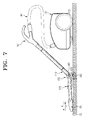
- FIG. 7 is a perspective view of a vacuum cleaner employing therein the articulative extension pipe of FIG. 6.
- an articulative extension pipe 100 includes a first extension pipe 110, a second extension pipe 120, a sealing cover 130, a locking button 140 and an elastic member 150.
- the first extension pipe 110 has a cylindrical joint J1 for insertion into a joint receiving part J2 of the second extension pipe 120.
- the cylindrical joint J1 has an elongated hole 117 in its front side for maintaining a fluid communication with the suction port 121 even when the first extension pipe 110 is in bent position.
- the cylindrical joint J1 has a second coupling recess 112 in its circumference in a position corresponding to the first coupling recess 131c of the first cover 131.
- the cylindrical joint J1 has a third coupling recess 114 in a bottom side in a position corresponding to the first coupling recess 131 c.
- the second coupling recess 112 is defined by the cooperation of a plurality of protrusions 111.
- a pair of protrusions 111 defines one second coupling recess 112.
- a total of eight (8) protrusions 111 are used to define a total of four (4) coupling recesses 112.
- the third coupling recess 114 is defined by the cooperation of a plurality oflinear or curvilinear protrusions 113.
- a pair of linear protrusions 113 define a third coupling recess 114. That is, a pair of protrusions 113 form a third coupling recess 114, and as shown in the embodiment shown in FIG. 2, a total of four (4) linear protrusions 113 are used to define a total of four (4) coupling recesses 114.
- the cylindrical joint J1 has a first seating hole 115 at the center of the bottom, for the elastic member 150 to seat thereon.
- the second extension pipe 120 has a joint receiving part J2 corresponding to the cylindrical joint J1, so that the cylindrical joint J1 of the first extension pipe 110 can be articulatively coupled therewith.
- the joint receiving part J2 has, in its front side, a cutaway oval part 122 and a connection part 123.
- the presence of the cutaway oval part 122 limits the angle ( ⁇ ) of articulative movement of the first extension pipe 110.
- Due to the connection part 123 the joint part J1 of the first extension pipe 110 is enabled to insert into the joint receiving part J2 in the direction indicated by the arrow A.
- a reference numeral 125 indicates a button for attaching or detaching another extension pipe to the second extension pipe 120.
- the sealing cover 130 prevents loss of suction force between the joints J1 and J2 of the first and second extension pipes 110 and 120, and also prevents separation of the locking button 140.
- the sealing cover 130 includes first and second covers 131 and 132.
- the first and second covers 131 and 132 are coupled by screws, and the first cover 131 has a first cut 131d and the second cover 132 has a second cut 132d.
- the first and second cuts 131d and 132d define, in an exemplary embodiment, an opening having a shape and size that corresponds to that of the oval shape defined in cutaway oval part 122. Accordingly, due to the presence of the first and second cuts 131d and 132d, the first extension pipe 110 is movable in the direction of arrow G or arrow H as shown in FIG. 5A even when the first and second covers 131 and 132 are connected with each other.
- the first cover 131 has a button hole 131a sized to correspond to the outer circumference of the locking button 140. Accordingly, the locking button 140 is exposed to the outside through the button hole 131a.
- the button hole 131a has a first coupling recess 131c formed in its circumference.
- the first coupling recess 131c is formed by the cooperation of a plurality of protrusions 131b. That is, a pair of protrusions 131b form a first coupling recess 131c, and as shown in this embodiment, a total of four (4) protrusions 131b may be used to form a total of four (4) first coupling recesses.
- Each of the protrusions 131b is formed in a stepwise manner to form a friction part 131bb (see FIG. 3). Accordingly, as shown in FIG. 5A, when the locking button 140 is pushed to the direction of arrow A, upper part 143aa (see FIG. 2) of the coupling protrusion 141 contacts with the friction part 131bb and slides.
- the locking button 140 includes a press part 141, a anti-separation part 142 and a coupling protrusion 143.
- the press part 141 is a cylindrical protrusion for insertion into the button hole 131a in the direction indicated by an arrow B. When pushed by the user, the press part 141 pushes the locking button 140.
- the press part 141 has, on its rear side, a second seating hole 141a for the elastic member 150 to seat thereon, and there is a cross part 141 aa provided at the center of the second seating hole 141 a to which a part of the elastic member 150 is inserted to more firmly support the elastic member 150.
- the anti-separation part 142 is an annular plate which encloses the press part 141 so that the press part 141 can prevent the locking button 140 from passing through the button hole 131a in the direction of arrow B once the locking button 140 is inserted.
- the coupling protrusion 143 includes first and second coupling protrusion parts 143a and 143b.
- the first coupling protrusion part 143a is a quadrangle, which is formed on the circumference of the press part 141 and above the anti-separation part 142. Referring to FIGS. 4B and 5B, the first coupling protrusion part 143a remains inserted in the first coupling recess 131c during release of the locking button 140 (FIG. 4B), and separates from the first coupling recess 131c when the locking button 140 is pushed in the direction of arrow A (FIG. 5B).
- the second coupling protrusion part 143b is connected with the first coupling protrusion part 143a.
- the second coupling protrusion part 143b also is a quadrangle, but is slimmer than the first coupling protrusion part 143a.
- the second coupling protrusion part 143b remains inserted in the second coupling recess 112 during the release of the locking button 140 (FIG. 4B), and is inserted in both the second and third coupling recesses 112 and 114 when the locking button 140 is pushed in the direction of arrow A (FIG. 5B).
- the first coupling protrusion part 143a can be separated from the first coupling recess 131c, and therefore, the first extension pipe 110 is enabled to move.
- the present embodiment depicts four coupling protrusions 143 arranged radially around the press part 141.
- this is only for the exemplary purpose, and therefore, the number of coupling protrusions 143 may vary as necessary.
- two coupling protrusions 143 can be provided in a symmetrical relation with each other.
- the elastic member 150 can be a coil spring seated between the first and the second seating holes 115 and 141 a.
- the elastic member 150 biases the locking button 140 to the arrowed direction B, the direction in which the locking button 140 is moved further away from the first extension pipe 110. Accordingly, when the force that was pushing the locking button 140 is removed, the locking button 140 can automatically be released.
- FIG. 4A shows the relation between the first, second and third coupling recesses 131c, 112, 114 and the coupling protrusion 141 before the articulative bending of the first extension pipe 110.
- illustration of the sealing cover 130 is omitted except for the area where the first coupling recess 131 c is formed.
- FIG. 4B particularly shows the main part of FIG. 4A in cross section.
- the angle ( ⁇ ) of articulative movement (FIG. 5A) is fixed at 0°.
- the first coupling protrusion part 143a is inserted in the first coupling recess 131c
- the second coupling protrusion part 143b is inserted in the second coupling recess 112.
- the first extension pipe 110 is restricted to move in the direction indicated by arrow G, because the first coupling protrusion part 143a is inserted in the first coupling recess 131 c of the first cover 131, which is fixed with respect to the first extension pipe 110.
- FIG. 5A shows the relation between the first, second and third coupling recesses 131 c, 112, 114 and the coupling protrusion 141 after the articulative movement of the first extension pipe 110.
- illustration of the sealing cover 130 is omitted except for the area where the first coupling recess 131c is formed.
- FIG. 5B particularly shows the main part of FIG. 5A in cross section.
- the user may bend the first extension pipe 110 in the direction of arrow G so as to clean the spaces under the bed or the couch with ease.
- the user pushes the locking button 130 in the direction of arrow A.
- the locking button 130 is pushed, from the state shown in FIGS. 4A and 4B, the first coupling protrusion part 143a is separated from the first coupling recess 131c, and the second coupling protrusion part 143b is inserted in both of the second and third coupling recesses 112 and 114 (FIGS. 5A and 5B).
- the first coupling protrusion part 143a when the first coupling protrusion part 143a is separated from the first coupling recess 131c, the upper side 143aa of the first coupling protrusion part 143a in the position as indicated by arrow E in FIG. 4A, contacts the friction part 131bb and moves to the position as indicated by arrow F of FIG. 5A. Therefore, unlike in the situation as shown in FIG. 5A, the first extension pipe 110 is no more restricted by the first cover 131, and freely moves in the direction of arrow G.
- the angle ( ⁇ ) of articulative movement may preferably be 45° at the maximum.
- the angle ( ⁇ ) of articulative movement may be adjusted by the cutaway part 122 (FIG. 2) of the joint receiving part J2 of the second extension pipe 120 and/or the first and second cuts 131d and 132d of first and second covers 131 and 132, when assembled.
- the user With the completion of cleaning on the space under the furniture, the user un-bends the first extension pipe 110 to the angle ( ⁇ ) of articulative movement of 0°.
- the user may directly un-bend the first extension pipe 110 in the direction of arrow H.
- the user may hold the first extension pipe 110 to a predetermined height so that the second extension pipe 120 can drop by its own weight, letting the first extension pipe 110 un-bend in the direction of arrow H.
- the locking button 140 is exposed through the button hole 131 a (FIG. 2) due to recovery force of the elastic member 150 (FIG. 2), and at the same time, the first coupling protrusion part 143a is re-inserted in the first coupling recess 131c. As a result, the first extension pipe 110 unfolds.
- the articulative extension pipe 200 according to the second embodiment of the present invention will now be described with reference to FIGS. 6 and 7.
- the elements that are similar to, or identical with those of the first embodiment will be referenced by the same reference numerals and the elements that are already described in the first embodiment will not be described.
- the sealing cover 130 further includes a wheel 160, which runs in contact with the surface 10 being cleaned.
- a cotton flannel 170 is disposed on the outer circumference of the wheel 160.
- the wheel 160 is rotatably disposed on the lower end of the sealing cover 130.
- the wheel 160 may preferably be formed of rubber or urethane so that it can roll smoothly, without giving any damage to the surface 10 being cleaned.
- the wheel 160 rotates in the direction of arrow C when the user pushes the suction brush 20 in the direction of arrow X with the bent extension pipe 200 for the cleaning of the space under the furniture.
- the wheel 160 rotates in the direction of arrow D when the suction brush 20 is pulled to the direction of arrow Y.
- the cotton flannel 170 are planed on the outer circumference of the wheel 160, and therefore, the wheel 160 rotates in the direction of C or D due to the friction between the cotton flannel 170 and the surface 10 being cleaned.
- the sealing cover 130 does not directly touch the surface 10 being cleaned when the bent extension pipe 200 is at cleaning operation with respect to the space under the furniture.
- the articulation part does not directly contact the surface 10 being cleaned. Accordingly, damages to the surface 10 being cleaned - especially the carpet - or the sealing cover 130 due to the friction therebetween.
- the suction brush 20 is smoothly moved. Because it becomes easier to push or pull the suction brush 20, user convenience in operating the vacuum cleaner also increases.
- the cotton flannel 170 includes a plurality of bristles, and is attached or press-fit to the outer circumference of the wheel 160. Due to the presence of the cotton flannel 170, damages to the surface 10 being cleaned, especially the carpet, can be effectively prevented. More specifically, because soft texture of the cotton flannel 170 protects the surface 10 being cleaned, impact can be reduced compared to when the wheel 160 directly contacts the surface 10 being cleaned.
- a reference numeral 30 denotes a cleaner body, 40 denotes a flexible hose, and 50 denotes an operation part.
- the user can have the extension pipe bend by a simple manipulation of a locking button, and therefore, the user is freed from the physical burden of bending or lowering his body. Accordingly, the user convenience increases and user can clean even the limited spaces under the furniture such as bed or couch with ease.
- the coupling protrusion of the locking button is inserted in both of the first and second coupling recesses. Therefore, the first and second extension pipes can be firmly fastened with each other, and the reliability increases.
- first and second extension pipes can be freely moved, or fixed in relative with each other with the simple cooperation between the coupling protrusion and first, second and third coupling recesses. Accordingly, the articulative extension pipe can have simple structure, and manufacturing cost decreases.
Landscapes
- Engineering & Computer Science (AREA)
- Mechanical Engineering (AREA)
- Electric Vacuum Cleaner (AREA)
Applications Claiming Priority (2)
| Application Number | Priority Date | Filing Date | Title |
|---|---|---|---|
| KR20050003689 | 2005-01-14 | ||
| KR1020050012644A KR20060083095A (ko) | 2005-01-14 | 2005-02-16 | 진공청소기용 굴절 연장관 |
Publications (1)
| Publication Number | Publication Date |
|---|---|
| EP1683464A2 true EP1683464A2 (de) | 2006-07-26 |
Family
ID=36255792
Family Applications (1)
| Application Number | Title | Priority Date | Filing Date |
|---|---|---|---|
| EP05356173A Withdrawn EP1683464A2 (de) | 2005-01-14 | 2005-09-26 | Gelenkigen Verlängungsrohr für Staubsauger |
Country Status (5)
| Country | Link |
|---|---|
| US (1) | US20060156510A1 (de) |
| EP (1) | EP1683464A2 (de) |
| JP (1) | JP2006192248A (de) |
| AU (1) | AU2005211695B2 (de) |
| RU (1) | RU2311867C2 (de) |
Cited By (1)
| Publication number | Priority date | Publication date | Assignee | Title |
|---|---|---|---|---|
| EP4278937A1 (de) * | 2022-05-19 | 2023-11-22 | Beijing Xiaomi Mobile Software Co., Ltd. | Biegbares gelenk, reinigerverbindungsrohr und reiniger |
Families Citing this family (41)
| Publication number | Priority date | Publication date | Assignee | Title |
|---|---|---|---|---|
| KR100572891B1 (ko) * | 2003-10-20 | 2006-04-24 | 삼성광주전자 주식회사 | 진공청소기의 굴절 연장관 |
| US8296901B2 (en) * | 2008-01-24 | 2012-10-30 | Euro-Pro Operating Llc | Reconfigurable airflow wand |
| TWI391116B (zh) * | 2008-04-22 | 2013-04-01 | Hitachi Appliances Inc | Electric vacuum cleaner |
| JP5055190B2 (ja) * | 2008-04-22 | 2012-10-24 | 日立アプライアンス株式会社 | 電気掃除機 |
| US20100229315A1 (en) * | 2009-03-12 | 2010-09-16 | Euro-Pro Operating Llc | Handle for surface cleaning apparatus |
| US9138114B2 (en) | 2009-03-13 | 2015-09-22 | Omachron Intellectual Property Inc. | Surface cleaning apparatus |
| CA2674761C (en) | 2009-03-13 | 2016-10-04 | G.B.D. Corp. | Surface cleaning apparatus with different cleaning configurations |
| US9226633B2 (en) | 2009-03-13 | 2016-01-05 | Omachron Intellectual Property Inc. | Surface cleaning apparatus |
| US9480373B2 (en) | 2009-03-13 | 2016-11-01 | Omachron Intellectual Property Inc. | Surface cleaning apparatus |
| US9591953B2 (en) | 2009-03-13 | 2017-03-14 | Omachron Intellectual Property Inc. | Surface cleaning apparatus |
| US9392916B2 (en) | 2009-03-13 | 2016-07-19 | Omachron Intellectual Property Inc. | Surface cleaning apparatus |
| US9427122B2 (en) | 2009-03-13 | 2016-08-30 | Omachron Intellectual Property Inc. | Surface cleaning apparatus |
| US8813297B2 (en) * | 2010-03-12 | 2014-08-26 | Euro-Pro Operating Llc | Floor cleaning device |
| JP2011224224A (ja) * | 2010-04-22 | 2011-11-10 | Hitachi Appliances Inc | 電気掃除機 |
| CN102727139B (zh) * | 2011-04-14 | 2014-12-17 | 科沃斯机器人有限公司 | 用于吸尘器的伸缩管 |
| US9215960B2 (en) | 2013-02-28 | 2015-12-22 | Omachron Intellectual Property Inc. | Surface cleaning apparatus |
| USD744184S1 (en) * | 2014-02-20 | 2015-11-24 | Samsung Electronics Co., Ltd. | Cleaner |
| USD740506S1 (en) * | 2014-02-20 | 2015-10-06 | Samsung Electronics Co., Ltd. | Cleaner |
| USD743649S1 (en) * | 2014-02-20 | 2015-11-17 | Samsung Electronics Co., Ltd. | Cleaner |
| USD745232S1 (en) * | 2014-02-20 | 2015-12-08 | Samsung Electronics Co., Ltd. | Cleaner |
| JP6129811B2 (ja) * | 2014-12-01 | 2017-05-17 | 日立アプライアンス株式会社 | 電気掃除機 |
| USD810369S1 (en) * | 2015-03-26 | 2018-02-13 | Samsung Electronics Co., Ltd. | Cleaner |
| KR102321298B1 (ko) * | 2015-09-07 | 2021-11-03 | 삼성전자주식회사 | 오물흡입가이드장치 및 이를 포함하는 청소기 |
| US10966581B2 (en) * | 2015-10-22 | 2021-04-06 | Sharkninja Operating Llc | Vacuum cleaning device with foldable wand to provide storage configuration |
| US10729295B2 (en) | 2016-08-29 | 2020-08-04 | Omachron Intellectual Property Inc. | Surface cleaning apparatus |
| US10441124B2 (en) | 2016-08-29 | 2019-10-15 | Omachron Intellectual Property Inc. | Surface cleaning apparatus |
| US11478117B2 (en) | 2016-08-29 | 2022-10-25 | Omachron Intellectual Property Inc. | Surface cleaning apparatus |
| US10413141B2 (en) | 2016-08-29 | 2019-09-17 | Omachron Intellectual Property Inc. | Surface cleaning apparatus |
| US10136779B2 (en) | 2016-08-29 | 2018-11-27 | Omachron Intellectual Property Inc. | Surface cleaning apparatus |
| US10321794B2 (en) | 2016-08-29 | 2019-06-18 | Omachron Intellectual Property Inc. | Surface cleaning apparatus |
| US9962050B2 (en) | 2016-08-29 | 2018-05-08 | Omachron Intellectual Property Inc. | Surface cleaning apparatus |
| US10441125B2 (en) | 2016-08-29 | 2019-10-15 | Omachron Intellectual Property Inc. | Surface cleaning apparatus |
| US10405711B2 (en) | 2016-08-29 | 2019-09-10 | Omachron Intellectual Property Inc. | Surface cleaning apparatus |
| US10292550B2 (en) | 2016-08-29 | 2019-05-21 | Omachron Intellectual Property Inc. | Surface cleaning apparatus |
| US10136780B2 (en) | 2016-08-29 | 2018-11-27 | Omachron Intellectual Property Inc. | Surface cleaning apparatus |
| US10433689B2 (en) | 2016-08-29 | 2019-10-08 | Omachron Intellectual Property Inc. | Surface cleaning apparatus |
| KR102321633B1 (ko) * | 2016-11-21 | 2021-11-05 | 삼성전자주식회사 | 청소기 및 이를 갖는 청소장치 |
| FR3088819B1 (fr) | 2018-11-22 | 2021-01-08 | Seb Sa | Conduit d’aspirateur pour aspirateur balai équipé d’un fil électrique |
| WO2021029654A1 (en) * | 2019-08-14 | 2021-02-18 | Samsung Electronics Co., Ltd. | Vacuum cleaner |
| JP7625728B2 (ja) | 2021-06-18 | 2025-02-03 | シャークニンジャ オペレーティング エルエルシー | 真空クリーナー用のワンド |
| USD1107192S1 (en) | 2023-10-31 | 2025-12-23 | Telebrands Corp. | Pivot connector |
Family Cites Families (4)
| Publication number | Priority date | Publication date | Assignee | Title |
|---|---|---|---|---|
| JP2001269294A (ja) * | 2000-03-23 | 2001-10-02 | Sharp Corp | 電気掃除機 |
| US6695352B2 (en) * | 2001-01-29 | 2004-02-24 | Lg Electronics Inc. | Extension tube in vacuum cleaner |
| SE519073C2 (sv) * | 2001-05-31 | 2003-01-07 | Electrolux Ab | Rörskaft för en dammsugare |
| KR20030072000A (ko) * | 2002-03-05 | 2003-09-13 | 삼성광주전자 주식회사 | 진공청소기의 관절조립체 및 이를 구비하는 진공청소기 |
-
2005
- 2005-06-17 JP JP2005177234A patent/JP2006192248A/ja active Pending
- 2005-08-19 US US11/207,454 patent/US20060156510A1/en not_active Abandoned
- 2005-09-26 AU AU2005211695A patent/AU2005211695B2/en not_active Expired - Fee Related
- 2005-09-26 EP EP05356173A patent/EP1683464A2/de not_active Withdrawn
- 2005-09-30 RU RU2005130314/12A patent/RU2311867C2/ru not_active IP Right Cessation
Cited By (2)
| Publication number | Priority date | Publication date | Assignee | Title |
|---|---|---|---|---|
| EP4278937A1 (de) * | 2022-05-19 | 2023-11-22 | Beijing Xiaomi Mobile Software Co., Ltd. | Biegbares gelenk, reinigerverbindungsrohr und reiniger |
| US12446746B2 (en) | 2022-05-19 | 2025-10-21 | Beijing Xiaomi Mobile Software Co., Ltd. | Bendable joint, cleaner connecting pipe, and cleaner |
Also Published As
| Publication number | Publication date |
|---|---|
| RU2005130314A (ru) | 2007-04-10 |
| JP2006192248A (ja) | 2006-07-27 |
| AU2005211695A1 (en) | 2006-08-03 |
| US20060156510A1 (en) | 2006-07-20 |
| RU2311867C2 (ru) | 2007-12-10 |
| AU2005211695B2 (en) | 2007-12-13 |
Similar Documents
| Publication | Publication Date | Title |
|---|---|---|
| EP1683464A2 (de) | Gelenkigen Verlängungsrohr für Staubsauger | |
| JP5055190B2 (ja) | 電気掃除機 | |
| RU2265390C1 (ru) | Удлинительная трубка для пылесоса с шарниром | |
| RU2261646C1 (ru) | Удлинительная труба с шарниром, предназначенная для пылесоса (варианты) | |
| KR100572891B1 (ko) | 진공청소기의 굴절 연장관 | |
| EP1382286B1 (de) | Gelenkverbindung für ein elektrisches Haushaltsgerät und elektrisches Haushaltsgerät mit einer solchen Verbindung | |
| JP5452065B2 (ja) | 電気掃除機 | |
| CN102232814B (zh) | 电动吸尘器 | |
| GB2386054A (en) | Joint assembly for a vacuum cleaner | |
| US7559112B2 (en) | Passage conversion valve assembly for a vacuum cleaner | |
| US7996954B2 (en) | Path-conversion valve assembly for vacuum cleaner | |
| EP1733673A2 (de) | Staubsauger | |
| EP1764021A1 (de) | Verlängerungsrohr für ein Haushaltsreinigungsgerät und Haushaltsreinigungsgerät mit solch einem Verlängerungsrohr | |
| JP2009297370A (ja) | 電気掃除機 | |
| CN100360072C (zh) | 真空吸尘器的铰接延伸管 | |
| JP3916609B2 (ja) | 電気掃除機 | |
| KR100730948B1 (ko) | 진공 청소기의 굴절 연장관 | |
| JP5719920B2 (ja) | 電気掃除機 | |
| EP2127582B1 (de) | Saugkopf für einen Staubsauger | |
| CN206434267U (zh) | 地刷组件和具有其的吸尘器 | |
| JP2005137684A (ja) | 電気掃除機用管継手及び電気掃除機 | |
| KR200489333Y1 (ko) | 접이 가능한 진공청소기의 흡입관 | |
| TWI391116B (zh) | Electric vacuum cleaner | |
| JP2005152038A (ja) | 電気掃除機用管継手及び電気掃除機 | |
| HK1061188A (en) | Articulated joint for an electric household appliance and electric household appliance comprising said joint |
Legal Events
| Date | Code | Title | Description |
|---|---|---|---|
| PUAI | Public reference made under article 153(3) epc to a published international application that has entered the european phase |
Free format text: ORIGINAL CODE: 0009012 |
|
| 17P | Request for examination filed |
Effective date: 20051001 |
|
| AK | Designated contracting states |
Kind code of ref document: A2 Designated state(s): AT BE BG CH CY CZ DE DK EE ES FI FR GB GR HU IE IS IT LI LT LU LV MC NL PL PT RO SE SI SK TR |
|
| AX | Request for extension of the european patent |
Extension state: AL BA HR MK YU |
|
| STAA | Information on the status of an ep patent application or granted ep patent |
Free format text: STATUS: THE APPLICATION HAS BEEN WITHDRAWN |
|
| 18W | Application withdrawn |
Effective date: 20080124 |