EP1683122B1 - System for detecting radio-frequency identification tags - Google Patents
System for detecting radio-frequency identification tags Download PDFInfo
- Publication number
- EP1683122B1 EP1683122B1 EP04795513A EP04795513A EP1683122B1 EP 1683122 B1 EP1683122 B1 EP 1683122B1 EP 04795513 A EP04795513 A EP 04795513A EP 04795513 A EP04795513 A EP 04795513A EP 1683122 B1 EP1683122 B1 EP 1683122B1
- Authority
- EP
- European Patent Office
- Prior art keywords
- tag
- signal
- antennas
- interrogation
- reader
- Prior art date
- Legal status (The legal status is an assumption and is not a legal conclusion. Google has not performed a legal analysis and makes no representation as to the accuracy of the status listed.)
- Expired - Lifetime
Links
Images


Classifications
-
- G—PHYSICS
- G06—COMPUTING OR CALCULATING; COUNTING
- G06K—GRAPHICAL DATA READING; PRESENTATION OF DATA; RECORD CARRIERS; HANDLING RECORD CARRIERS
- G06K17/00—Methods or arrangements for effecting co-operative working between equipments covered by two or more of main groups G06K1/00 - G06K15/00, e.g. automatic card files incorporating conveying and reading operations
-
- G—PHYSICS
- G06—COMPUTING OR CALCULATING; COUNTING
- G06K—GRAPHICAL DATA READING; PRESENTATION OF DATA; RECORD CARRIERS; HANDLING RECORD CARRIERS
- G06K7/00—Methods or arrangements for sensing record carriers, e.g. for reading patterns
- G06K7/08—Methods or arrangements for sensing record carriers, e.g. for reading patterns by means detecting the change of an electrostatic or magnetic field, e.g. by detecting change of capacitance between electrodes
-
- G—PHYSICS
- G06—COMPUTING OR CALCULATING; COUNTING
- G06K—GRAPHICAL DATA READING; PRESENTATION OF DATA; RECORD CARRIERS; HANDLING RECORD CARRIERS
- G06K7/00—Methods or arrangements for sensing record carriers, e.g. for reading patterns
- G06K7/10—Methods or arrangements for sensing record carriers, e.g. for reading patterns by electromagnetic radiation, e.g. optical sensing; by corpuscular radiation
- G06K7/10009—Methods or arrangements for sensing record carriers, e.g. for reading patterns by electromagnetic radiation, e.g. optical sensing; by corpuscular radiation sensing by radiation using wavelengths larger than 0.1 mm, e.g. radio-waves or microwaves
- G06K7/10019—Methods or arrangements for sensing record carriers, e.g. for reading patterns by electromagnetic radiation, e.g. optical sensing; by corpuscular radiation sensing by radiation using wavelengths larger than 0.1 mm, e.g. radio-waves or microwaves resolving collision on the communication channels between simultaneously or concurrently interrogated record carriers.
- G06K7/10029—Methods or arrangements for sensing record carriers, e.g. for reading patterns by electromagnetic radiation, e.g. optical sensing; by corpuscular radiation sensing by radiation using wavelengths larger than 0.1 mm, e.g. radio-waves or microwaves resolving collision on the communication channels between simultaneously or concurrently interrogated record carriers. the collision being resolved in the time domain, e.g. using binary tree search or RFID responses allocated to a random time slot
- G06K7/10039—Methods or arrangements for sensing record carriers, e.g. for reading patterns by electromagnetic radiation, e.g. optical sensing; by corpuscular radiation sensing by radiation using wavelengths larger than 0.1 mm, e.g. radio-waves or microwaves resolving collision on the communication channels between simultaneously or concurrently interrogated record carriers. the collision being resolved in the time domain, e.g. using binary tree search or RFID responses allocated to a random time slot interrogator driven, i.e. synchronous
-
- G—PHYSICS
- G08—SIGNALLING
- G08B—SIGNALLING SYSTEMS, e.g. PERSONAL CALLING SYSTEMS; ORDER TELEGRAPHS; ALARM SYSTEMS
- G08B13/00—Burglar, theft or intruder alarms
- G08B13/22—Electrical actuation
- G08B13/24—Electrical actuation by interference with electromagnetic field distribution
- G08B13/2402—Electronic Article Surveillance [EAS], i.e. systems using tags for detecting removal of a tagged item from a secure area, e.g. tags for detecting shoplifting
- G08B13/2451—Specific applications combined with EAS
- G08B13/2462—Asset location systems combined with EAS
-
- G—PHYSICS
- G08—SIGNALLING
- G08B—SIGNALLING SYSTEMS, e.g. PERSONAL CALLING SYSTEMS; ORDER TELEGRAPHS; ALARM SYSTEMS
- G08B13/00—Burglar, theft or intruder alarms
- G08B13/22—Electrical actuation
- G08B13/24—Electrical actuation by interference with electromagnetic field distribution
- G08B13/2402—Electronic Article Surveillance [EAS], i.e. systems using tags for detecting removal of a tagged item from a secure area, e.g. tags for detecting shoplifting
- G08B13/2465—Aspects related to the EAS system, e.g. system components other than tags
- G08B13/2468—Antenna in system and the related signal processing
- G08B13/2474—Antenna or antenna activator geometry, arrangement or layout
-
- G—PHYSICS
- G08—SIGNALLING
- G08B—SIGNALLING SYSTEMS, e.g. PERSONAL CALLING SYSTEMS; ORDER TELEGRAPHS; ALARM SYSTEMS
- G08B13/00—Burglar, theft or intruder alarms
- G08B13/22—Electrical actuation
- G08B13/24—Electrical actuation by interference with electromagnetic field distribution
- G08B13/2402—Electronic Article Surveillance [EAS], i.e. systems using tags for detecting removal of a tagged item from a secure area, e.g. tags for detecting shoplifting
- G08B13/2465—Aspects related to the EAS system, e.g. system components other than tags
- G08B13/248—EAS system combined with another detection technology, e.g. dual EAS and video or other presence detection system
-
- G—PHYSICS
- G08—SIGNALLING
- G08B—SIGNALLING SYSTEMS, e.g. PERSONAL CALLING SYSTEMS; ORDER TELEGRAPHS; ALARM SYSTEMS
- G08B13/00—Burglar, theft or intruder alarms
- G08B13/22—Electrical actuation
- G08B13/24—Electrical actuation by interference with electromagnetic field distribution
- G08B13/2402—Electronic Article Surveillance [EAS], i.e. systems using tags for detecting removal of a tagged item from a secure area, e.g. tags for detecting shoplifting
- G08B13/2465—Aspects related to the EAS system, e.g. system components other than tags
- G08B13/2485—Simultaneous detection of multiple EAS tags
-
- G—PHYSICS
- G08—SIGNALLING
- G08B—SIGNALLING SYSTEMS, e.g. PERSONAL CALLING SYSTEMS; ORDER TELEGRAPHS; ALARM SYSTEMS
- G08B13/00—Burglar, theft or intruder alarms
- G08B13/22—Electrical actuation
- G08B13/24—Electrical actuation by interference with electromagnetic field distribution
- G08B13/2402—Electronic Article Surveillance [EAS], i.e. systems using tags for detecting removal of a tagged item from a secure area, e.g. tags for detecting shoplifting
- G08B13/2465—Aspects related to the EAS system, e.g. system components other than tags
- G08B13/2488—Timing issues, e.g. synchronising measures to avoid signal collision, with multiple emitters or a single emitter and receiver
-
- G—PHYSICS
- G08—SIGNALLING
- G08C—TRANSMISSION SYSTEMS FOR MEASURED VALUES, CONTROL OR SIMILAR SIGNALS
- G08C17/00—Arrangements for transmitting signals characterised by the use of a wireless electrical link
Definitions
- the invention relates to the use of radio frequency identification systems for management of articles within a protected area and, more specifically, to techniques for detecting unauthorized removal of articles from a protected area.
- RFID Radio-Frequency Identification
- An RFID system often includes an interrogation zone or corridor located near the exit of a protected area for detection of RFID tags attached to the articles to be protected.
- Each tag usually includes information that uniquely identifies the article to which it is affixed.
- the article may be a book, a manufactured item, a vehicle, an animal or individual, or virtually any other tangible article. Additional data as required by the particular application may also be provided for the article.
- the RF reader To detect a tag, the RF reader outputs RF signals through the antenna to create an electromagnetic field within the interrogation corridor.
- the field activates tags within the corridor.
- the tags produce a characteristic response.
- the tags once activated, the tags communicate using a pre-defined protocol, allowing the RFID reader to receive the identifying information from one or more tags in the corridor. If the communication indicates that removal of an article has not been authorized, the RFID system initiates some appropriate security action, such as sounding an audible alarm, locking an exit gate, and the like.
- This process can be time-consuming, especially if several tags exist in the field. For example, in order to obtain a complete tag serial number, only one tag can respond at a time. If more than one tag responds at a time, a collision occurs, the data received may be invalid, and neither tag's serial number can be obtained. To deal with this, some systems use an anti-collision process, which requires each tag to respond in a different time slot until all tags are heard. This added delay is undesirable in an exit control system because patrons are in the interrogation corridor for a very short period of time. Also, each patron can be carrying multiple books. The time required to determine whether every one of the books is checked-out is often much longer than the time a patron spends in the corridor.
- US 2002/0 044 096 discloses a system comprising a plurality of radio frequency antennae which are coupled to a RF reader.
- EP 0 435 198 discloses a tag detection system with a single interrogation corridor, the system combining a patron signal and a tag detection signal in order to reduce false alarms.
- US 5,353,011 discloses an electronic article surveillance system with one or more tag detection systems, the system combining detection of a person and a tag detection signal in order to reduce false alarms. An alarm is generated when a person is present within one of the corridors and a tag is detected within one of the corridors within a time period.
- the invention relates to a Radio-Frequency Identification (RFID) system for detecting radio-frequency identification tags according to claim 1, to a method for detecting radio-frequency identification tags according to claim 10, and a computer-readable medium comprising instructions for a processor for detecting radio-frequency identification tags according to claim 18.
- RFID Radio-Frequency Identification
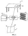
- FIG. 1 is a block diagram illustrating a radio frequency identification (RFID) system 10.
- Exit control system 5 detects unauthorized removal of articles from a protected area 7.
- the protected area will be assumed to be a library and the articles will be assumed to be books or other articles to be checked out.
- the system will be described with respect to detecting checked-in tags to prevent their unauthorized removal from a facility, it shall be understood that the present invention is not limited in this respect, and that the techniques described herein are not dependent upon the particular application in which the RFID system is used. For example, the system could also be used to check for other kinds of status or type information without departing from the scope of the present invention.
- Exit control system 5 includes lattices 9A and 9B which define an interrogation zone or corridor located near the exit of protected area 7.
- the lattices 9A and 9B include antennas for interrogating the RFID tags as they pass through the corridor to determine whether removal of the item to which the tag is attached is authorized.
- exit control system 5 utilizes a single reader to drive multiple antennas.
- an RF reader outputs RF power through the antennas to create an electromagnetic field within the interrogation corridor.
- the RF reader outputs RF power from a single port to multiple antennas via a splitter/combiner. In this way, a single RF reader with only one transmitter/receiver port simultaneously interrogates the corridor using multiple antennas.
- the field activates the tags and the tags, in turn, produce a characteristic response.
- the RF reader receives the tag information via the single transmitter/receiver port and the exit control system determines whether removal of the article is authorized. If removal of the article is not authorized, the exit control system initiates some appropriate security action, such as sounding an audible alarm, locking an exit gate, etc.
- the overall RFID system 10 may include a number of "smart storage areas" 12 within protected area 7.
- a smart storage area 12 includes tag interrogation capability which enables tracking of articles throughout a facility.
- a book could be tracked after check-in while en route to a shelf 12A on a smart cart 12C.
- the RFID tags themselves may take any number of forms without departing from the scope of the present invention. Examples of commercially available RFID tags include 3M TM RFID tags available from 3M Company, St. Paul, MN, or "Tag-it" RFID transponders available from Texas Instruments, Dallas, TX.
- An RFID tag typically includes an integrated circuit operatively connected to an antenna that receives RF energy from a source and backscatters RF energy in a manner well known in the art. The backscattered RF energy provides a signal that may be received by an interrogator within RFID system 10 to obtain information about the RFID tag, and its associated article.
- An article management system 14 provides a centralized database of the tag information for each article in the facility.
- Article management system 14 may be networked or otherwise coupled to one or more computers so that individuals, such as a librarian, at various locations, can access data relative to those items. For example, a user may request the location and status of a particular article, such as a book.
- Article management system 14 may retrieve the article information from a database, and report to the user the last location at which the article was located within one of the smart storage areas.
- the system can re-poll or otherwise re-acquire the current location of the article to verify that the article is in the location indicated in the database.
- FIG. 2 shows a more detailed block diagram of an example embodiment of the RFID exit control system 5.
- exit control system 5 is configured for transmitting and/or receiving data from one port of RF reader 20 to/from multiple antennas according to the techniques described herein.
- exit control system 5 includes antennas 8A, 8B and 8C (collectively referred to as "antennas 8") positioned to provide multiple interrogation zones 40A and 40B.
- Each antenna 8A-C includes an associated tuner 18A-C through which the antennas are connected to RF reader 20 and ultimately to controller 14.
- FIG. 2 shows system 10 as including three antennas 8A-8C and two interrogation zones 40A and 40B, it shall be understood that exit control system 5 can include any number of antennas set to provide any number of interrogation zones depending upon the needs of the facility.
- the field produced may have a magnitude that exceeds the threshold magnitude for 50%, 75%, 90%, 99%, or more of the volume of the interrogation corridor, thus increasing the likelihood that unauthorized (i.e., tags that are still checked-in) RF tags in the corridor are successfully detected.
- RF reader 20 receives a response from the RFID tags through the same splitter/combiner 42 and transmitter/receiver port 21.
- the received signal is analyzed by the system to determine whether a checked-in (e.g., not checked out) article is present in an interrogation corridor 40.
- RF reader 20 receives a response from the RFID tags through the same splitter/combiner 42, the return signal from any RF tags in the corridor are combined going back through the splitter/combiner 42 into the RF reader transmitter/receiver port 21.
- the two weak signals from antennas 8A and 8B are combined at splitter/combiner 42.
- the combined signal is then input into RF reader 20 through transmitter/receiver port 21. This greatly increases the likelihood detecting even weak tag signals.
- the present exit control system is thus designed such that even when numerous tags are present in the corridor, if at least one of them has checked-in status, the system will alarm. Similarly, when numerous tags are present in the corridor and more than one of them has checked-in status, the system will alarm.
- the librarian or other designated employee can then check the articles to determine which of the articles present when the system alarmed have not been properly checked-out.
- the methods by which the system may determine presence of a checked-in tag i.e., one that has not been properly checked-out and is therefore not authorized to be removed from the facility are described in further detail below with respect to FIGS. 7-14.
- Photocells 24A and 24B one for each interrogation corridor 40A and 40B, respectively, signal presence of a patron in their respective corridors.
- Interconnects 16A, 16B and 16C connect the alarms 12 and photocells 24 to controller 14.
- a counter 22 may also be included which increments each time one of photocells 24 detect a patron in the corridor.
- each antenna 8 nominally receives the same amount of RF power from RF reader 20, but, as will be described in more detail below, is driven ninety degrees out of phase with its neighboring antennas.
- the phase shift by creating a rotating field between antennas, enhances the ability of the system to detect tags regardless of the orientation of the tag.
- the exit control system 5 transmits and receives from one RF reader transmitter/receiver port 21 to multiple antennas 8 via a splitter/combiner 42.
- Antennas 8 receive nominally the same amount of power from the RF reader, but are driven 90° out of phase with each other.
- FIG. 3 is a graph that shows the resulting phase shift of the RF drive signals 43A-C for each antenna 8A-8C (FIG. 2), respectively.
- the RF drive signal 43B for antenna 8B is 90° out of phase with the RF drive signal 43A for antenna 8A; the RF drive signal 43C for antenna 8C is 180° out of phase with antenna 8A, etc.
- phase shift allows the system to detect RF tags in all orientations by creating a rotating field between the antennas. Thus, regardless of the orientation of the RF tag as it travels through the interrogation corridor, the likelihood of detection is increased.
- the antennas are connected using transmission lines that differ by 1 ⁇ 4 wavelength between neighboring antennas to achieve the desired 90° phase shift.
- lines 32A, 32B and 32C which connect the antennas 8A, 8B and 8C to splitter/combiner 42 could be implemented by coupling lengths of 1 ⁇ 4 wave transmission lines as appropriate to drive each successive antenna 90° out of phase as shown in FIG. 3.
- FIG. 4 is a block diagram that illustrates controller 14 in further detail.
- controller 14 receives an input signal 45 from interconnect 16A that indicates a patron has been detected in corridors 40.
- controller 14 receives an input signal 47 from RF reader 20 that indicates that the RF reader has detected at least one signal within corridors 40In an embodiment, as described in further detail below, controller 14 continually monitors input signals 45 and 47. When input signals 45 and 47 indicate that both a patron and a checked-in tag have been detected, controller 14 initiates an alarm.
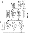
- FIG. 5 is a flowchart 50 further illustrating operation of controller 14.
- controller 14 performs a continuous loop monitoring that looks for a checked-in tag in the corridor, or for a patron to enter the corridor, and initiates an alarm only when both a patron and a checked-in RF tag are detected in an interrogation corridor.
- controller 14 continually monitors input signals 45 and 47 to determine whether a checked-in RF tag (52) or a patron (54) is present in any of corridors 40A or 40B. If either one of these conditions is met, controller 14 starts a timer (56 or 58, respectively). The purpose of the timer is to ensure presence of both a patron and a checked-in RF tag in the corridor at essentially the same time, for example, within 0.5 seconds, or some other time as may be appropriate.
- Controller 14 next determines whether the other criteria, namely either a patron (60) or a checked-in RF tag (62) is present. If not, controller 14 checks whether the timer has timed out (64 or 66, respectively). If so, then both a patron and a checked-in RF tag were not present within the allotted time frame, and controller 14 returns to the beginning of the loop. In the event that both a patron and a checked-in tag are present in the corridor within the allotted time frame, controller 14 activates the alarm (68).
- the techniques described herein allow RF reader 20 to quickly determine whether any articles that are not properly checked-out (in other words, articles that have checked-in status and are therefore not authorized to be removed from the facility) are in the interrogation corridor.
- the techniques allow RF reader 20 to rapidly and accurately determine the presence of articles with checked-in status in the corridor, and will minimizes the adverse impact of tag collisions that may otherwise degrade the system performance.
- the RF reader 20 and the RF tags communicate using a known protocol in which each message is embedded within one or more frames of a predefined format.
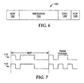
- the format of an example RFID transmission frame 100 is shown in FIG. 6.
- the frame 100 includes a start of frame (SOF) 102, a message 104, cyclical redundancy check (CRC) 106 and end of file (EOF) 108.
- SOF 102 indicates the beginning of the frame.
- EOF 108 indicates that the entire frame has been transmitted. Any non-fixed data is embedded in the message 104 portion of the frame 100 and CRC 106 reflects the data in the message 104.
- CRC 106 is used to check the integrity of the data. To calculate CRC 106, all bits of the data are pushed through a predetermined algorithm. Once the frame is transmitted, the receiver decodes CRC 106 using the received data to determine whether the message 104 was properly transmitted. If the CRC generated from the received data does not match the CRC contained within the frame itself, an error occurred.
- One aspect of the presently described techniques is directed to ensuring that only tags that are not checked-out (i.e., still checked-in) respond when passing through the interrogation corridor. This can be accomplished by making use of a feature called the Application Family Identifier (AFI) byte.
- AFI Application Family Identifier
- the AFI byte is a piece of memory in the RFID tag that contains one 8-bit value.
- the AFI is normally used to identify the type of article to which the tag is attached, such as book, CD, videotape, etc.
- the value stored in the AFI location can be changed through a defined series of commands described in the ISO 15693 standard. When the RF reader issues an AFI command it sends an AFI value.
- the techniques described herein use the AFI byte to indicate the status of the article, for example, whether the article has been checked-out.
- the AFI field is therefore used as a checked-in/checked-out status byte.
- the AFI byte is set to a designated "checked-in” value.
- a librarian checks out the book or a patron checks out at a self check station the AFI value is changed to a different, "checked-out" value.
- the RF reader scans for tags containing the checked-in value in their AFI memory location. This will cause all tags with their AFI byte set to "checked-in" to respond. If the RF reader receives a response from the tags then the item was not properly checked-out. This is because any item that was properly checked-out would not have the checked-in value in their AFI byte and would not respond.
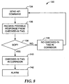
- FIG. 8 is a flowchart 130 of the present technique for verifying presence of an unchecked tag in an interrogation corridor using the AFI byte as a status byte and the SOF as verification that an unchecked tag is in the field.
- the RF reader sends the AFI command with the AFI value set to checked-in (134).
- Each tag with a matching checked-in AFI byte responds, and the possible checked-in tag response is received (136).
- the system checks for the SOF (138). If a valid SOF was received, at least one checked-in tag is present in the interrogation corridor (140) and the alarm is activated (142). The alarm is activated for a predetermined duration. On the other hand, if a valid SOF is not received, the system assumes that noise caused the response, and that therefore there is not a checked-in tag in the corridor (146). The loop then restarts by sending an AFI command (134).
- FIG. 9 shows an example of tag signal frame in the presence of noise.
- the tag signal 114 is shown on top of a noise floor 120. This noise floor is measured and analyzed as described below to verify a valid SOF.
- FIG. 12 shows another embodiment of a method by which the RF reader may determine whether a checked-in tag is present in the interrogation corridor.
- This process 250 is used with the "Tag-it" type tags available from Texas Instruments as mentioned above.
- There is a command in the Tag-it protocol where all tags in the interrogation field respond with the data stored in an defined block and they will all respond at the same time.
- the present technique sets one block of data in the tag as the "check-out status block.”
- the command is then used to determine whether at least one unchecked-out (checked-in) tag is in the field.
- the following discussion is directed toward a method for use with the new Electronic Product Code (EPC).
- EPC Electronic Product Code
- UPC Universal Product Code
- the EPC is set to supplant the Universal Product Code (UPC) in certain applications by using RFID for item identification.
- UPC Universal Product Code
- UPC Universal Product Code
- a "destroy” command that when executed renders the RFID tag destroyed or nonfunctional.
- the method creates a "key” for this destroy command which is difficult to detect as well as secure so that malicious use of the destroy command will not affect performance of the RFID tag.
- the present method creates a secure "key" for the destruction of RFID tags. If one key was used for all tags at all locations, if someone were to break the key, they could in theory destroy all RFID at that location. For example: Tag A Tag B Tag C Destroy Code: G G G
Landscapes
- Physics & Mathematics (AREA)
- Engineering & Computer Science (AREA)
- General Physics & Mathematics (AREA)
- Automation & Control Theory (AREA)
- Electromagnetism (AREA)
- Computer Security & Cryptography (AREA)
- Theoretical Computer Science (AREA)
- Health & Medical Sciences (AREA)
- Toxicology (AREA)
- Computer Networks & Wireless Communication (AREA)
- Artificial Intelligence (AREA)
- Computer Vision & Pattern Recognition (AREA)
- Signal Processing (AREA)
- General Health & Medical Sciences (AREA)
- Multimedia (AREA)
- Burglar Alarm Systems (AREA)
- Radar Systems Or Details Thereof (AREA)
- Near-Field Transmission Systems (AREA)
- Variable-Direction Aerials And Aerial Arrays (AREA)
Priority Applications (1)
| Application Number | Priority Date | Filing Date | Title |
|---|---|---|---|
| EP07113593A EP1852839B1 (en) | 2003-11-10 | 2004-10-18 | System for detecting radio-frequency identification tags |
Applications Claiming Priority (2)
| Application Number | Priority Date | Filing Date | Title |
|---|---|---|---|
| US10/705,677 US7119692B2 (en) | 2003-11-10 | 2003-11-10 | System for detecting radio-frequency identification tags |
| PCT/US2004/034366 WO2005048211A2 (en) | 2003-11-10 | 2004-10-18 | System for detecting radio-frequency identification tags |
Related Child Applications (1)
| Application Number | Title | Priority Date | Filing Date |
|---|---|---|---|
| EP07113593A Division EP1852839B1 (en) | 2003-11-10 | 2004-10-18 | System for detecting radio-frequency identification tags |
Publications (2)
| Publication Number | Publication Date |
|---|---|
| EP1683122A2 EP1683122A2 (en) | 2006-07-26 |
| EP1683122B1 true EP1683122B1 (en) | 2007-12-19 |
Family
ID=34552421
Family Applications (2)
| Application Number | Title | Priority Date | Filing Date |
|---|---|---|---|
| EP04795513A Expired - Lifetime EP1683122B1 (en) | 2003-11-10 | 2004-10-18 | System for detecting radio-frequency identification tags |
| EP07113593A Expired - Lifetime EP1852839B1 (en) | 2003-11-10 | 2004-10-18 | System for detecting radio-frequency identification tags |
Family Applications After (1)
| Application Number | Title | Priority Date | Filing Date |
|---|---|---|---|
| EP07113593A Expired - Lifetime EP1852839B1 (en) | 2003-11-10 | 2004-10-18 | System for detecting radio-frequency identification tags |
Country Status (11)
| Country | Link |
|---|---|
| US (2) | US7119692B2 (https=) |
| EP (2) | EP1683122B1 (https=) |
| JP (1) | JP4723507B2 (https=) |
| KR (1) | KR20060118474A (https=) |
| AT (2) | ATE381752T1 (https=) |
| AU (1) | AU2004289012B2 (https=) |
| BR (1) | BRPI0416347A (https=) |
| CA (1) | CA2545720A1 (https=) |
| DE (2) | DE602004025995D1 (https=) |
| TW (1) | TW200519759A (https=) |
| WO (1) | WO2005048211A2 (https=) |
Families Citing this family (55)
| Publication number | Priority date | Publication date | Assignee | Title |
|---|---|---|---|---|
| JP4019986B2 (ja) * | 2003-03-20 | 2007-12-12 | セイコーエプソン株式会社 | 非接触データ通信システム、位置情報管理システム、データ通信装置及びデータ通信装置制御プログラム |
| US7119692B2 (en) * | 2003-11-10 | 2006-10-10 | 3M Innovative Properties Company | System for detecting radio-frequency identification tags |
| US7372364B2 (en) * | 2003-11-10 | 2008-05-13 | 3M Innovative Properties Company | Algorithm for RFID security |
| US7420458B1 (en) | 2004-01-20 | 2008-09-02 | Charles A. Eldering | Secondary card reader |
| US7298264B1 (en) | 2004-01-20 | 2007-11-20 | Charles A. Eldering | RFID tag filtering and monitoring |
| EP1738295A1 (en) | 2004-03-03 | 2007-01-03 | Caducys L.L.C. | Interrogator and interrogation system employing the same |
| WO2005091889A2 (en) * | 2004-03-05 | 2005-10-06 | Seknion, Inc. | Method and apparatus for improving the efficiency and accuracy of rfid systems |
| WO2006072111A2 (en) * | 2004-12-30 | 2006-07-06 | Invitrogen Corporation | System and method for controlling access to a local inventory storage system via a remote e-commerce application |
| DE102005018402B4 (de) * | 2005-04-20 | 2009-10-01 | Gea Westfaliasurge Gmbh | Diagnoseverfahren sowie Diagnoseeinrichtung für ein Tieridentifikationssystem, insbesondere ein Tieridentifikationssystem einer Melkanlage und Melkanlage mit einem Tieridentifikationssystem |
| JP2006319710A (ja) * | 2005-05-13 | 2006-11-24 | Brother Ind Ltd | 無線タグ通信システム |
| US20070164865A1 (en) * | 2005-11-04 | 2007-07-19 | Gerald Giasson | Security sensor system |
| US7564354B2 (en) * | 2005-12-29 | 2009-07-21 | International Business Machines Corporation | Monitoring device for detecting opening of packaging |
| US7548165B2 (en) * | 2006-04-04 | 2009-06-16 | Pintey Bowes Inc. | Performance enhancement algorithm for radio frequency identification (RFID) systems |
| US7561044B2 (en) * | 2006-04-04 | 2009-07-14 | Pitney Bowes Inc. | Adaptive radio frequency identification control algorithm |
| US7663486B2 (en) * | 2006-06-16 | 2010-02-16 | Motorola, Inc. | RFID tag user memory indication |
| US20080065496A1 (en) * | 2006-08-29 | 2008-03-13 | Ncr Corporation | Methods and Apparatus for Managing RFID and Other Data |
| US8207826B2 (en) * | 2006-10-03 | 2012-06-26 | Ncr Corporation | Methods and apparatus for analyzing signal conditions affecting operation of an RFID communication device |
| KR100842958B1 (ko) * | 2006-10-19 | 2008-07-01 | 한국정보통신대학교 산학협력단 | Rfid 시스템의 쿼리 트리 기반 태그 인식 방법 |
| KR100845666B1 (ko) * | 2006-10-19 | 2008-07-10 | 한국정보통신대학교 산학협력단 | Rfid 시스템에서의 두 슬롯 트리 기반의 태그 인식 방법 |
| US20080120167A1 (en) * | 2006-11-17 | 2008-05-22 | Ac Technologies S.A. | Personal Inventory and Marketing Electronic System and Method |
| US7916022B2 (en) * | 2006-11-21 | 2011-03-29 | Deere & Company | Agricultural information gathering system |
| US20080204234A1 (en) * | 2007-02-28 | 2008-08-28 | Vijay Pillai | Systems and methods for increased memory capacity in a low-power environment |
| US20080278320A1 (en) * | 2007-05-07 | 2008-11-13 | Sensormatic Electronics Corporation | Method and system for reduction of electronic article surveillance system false alarms |
| CN101079111B (zh) * | 2007-05-30 | 2010-08-11 | 上海复旦天臣新技术有限公司 | 智能货架及货物监控方法 |
| US8330579B2 (en) | 2007-07-05 | 2012-12-11 | Baxter International Inc. | Radio-frequency auto-identification system for dialysis systems |
| KR101396430B1 (ko) * | 2007-10-31 | 2014-05-20 | 삼성전자주식회사 | 전자식별시스템에서 태그 충돌 방지 방법 및 장치 |
| NL2001161C2 (nl) * | 2008-01-07 | 2009-01-27 | Nedap Nv | Systeem voor detecteren van artikelen. |
| KR101204091B1 (ko) * | 2008-01-23 | 2012-11-22 | 한양대학교 산학협력단 | 인식 오류를 방지하는 rfid 시스템 및 그 통신 방법 |
| EP2294544A4 (en) | 2008-04-30 | 2013-01-16 | Ecolab Inc | VALIDATED HEALTHCARE CLEANING AND DISINFECTION PRACTICES |
| US8639527B2 (en) | 2008-04-30 | 2014-01-28 | Ecolab Usa Inc. | Validated healthcare cleaning and sanitizing practices |
| JP5183501B2 (ja) * | 2009-01-08 | 2013-04-17 | 三菱電機株式会社 | 判定装置及びコンピュータプログラム及び判定方法 |
| EP2441063B1 (en) | 2009-06-12 | 2015-03-11 | Ecolab USA Inc. | Hand hygiene compliance monitoring |
| USRE48951E1 (en) | 2015-08-05 | 2022-03-01 | Ecolab Usa Inc. | Hand hygiene compliance monitoring |
| US8610574B2 (en) | 2009-06-15 | 2013-12-17 | Gerald Isaac Kestenbaum | Item storage and tracking system |
| US9007181B2 (en) * | 2010-01-08 | 2015-04-14 | Tyco Fire & Security Gmbh | Method and system for discovery and transparent status reporting for sensor networks |
| ES2381542B1 (es) * | 2010-02-04 | 2013-05-08 | Agotek Desarrollo Tecnologico, S.L. | Sistema de aparcamiento seguro para bicicletas u otros objetos moviles o transportables por parte del ser humano |
| US8448072B1 (en) * | 2010-04-07 | 2013-05-21 | Sprint Communications Company L.P. | Interception of automatic status updates for a social networking system |
| DE102010054087A1 (de) * | 2010-12-10 | 2012-06-14 | Audi Ag | Verfahren zur drahtlosen Kommunikation zwischen einem Kraftfahrzeug und wenigstens einem anderen Kommunikationsteilnehmer und Kraftfahrzeug |
| US20140210620A1 (en) | 2013-01-25 | 2014-07-31 | Ultraclenz Llc | Wireless communication for dispenser beacons |
| DE102011005610A1 (de) * | 2011-03-16 | 2012-09-20 | Deutsche Post Ag | Verfahren und System zur Überwachung von Gegenständen |
| US9311586B2 (en) | 2011-03-22 | 2016-04-12 | Jamie Robinette | Apparatus and method for locating, tracking, controlling and recognizing tagged objects using active RFID technology |
| US8717165B2 (en) | 2011-03-22 | 2014-05-06 | Tassilo Gernandt | Apparatus and method for locating, tracking, controlling and recognizing tagged objects using RFID technology |
| US8536816B2 (en) | 2011-09-12 | 2013-09-17 | General Electric Company | Method and system for detecting faults in a brushless exciter |
| US8836197B2 (en) | 2012-03-23 | 2014-09-16 | General Electric Company | Brush holder having radio frequency identification (RFID)temperature monitoring system |
| EP2932477B1 (en) | 2012-12-12 | 2019-04-24 | Life Technologies Corporation | Self-locking door and product dispensing enclosure having a self-locking door |
| CN106030606B (zh) * | 2014-02-21 | 2019-07-05 | 索尼公司 | 检测未授权标签的计算机实现方法和移动通信终端 |
| CN106462778A (zh) * | 2014-05-13 | 2017-02-22 | 惠普发展公司,有限责任合伙企业 | 可穿戴验证 |
| TWI650730B (zh) * | 2014-07-21 | 2019-02-11 | 中國鋼鐵股份有限公司 | 載送板台移動識別系統 |
| US10614413B2 (en) | 2014-10-24 | 2020-04-07 | Life Technologies Corporation | Inventory management system and method of use |
| DK178276B1 (en) | 2014-12-19 | 2015-10-26 | Conpleks Innovation Aps | Method for recording and predicting position data for a selfpropelled wheeled vehicle, and delivery or pick up system comprising a self-propelled, self-guided wheeled vehicle |
| CN110383355B (zh) | 2017-03-07 | 2021-08-27 | 埃科莱布美国股份有限公司 | 用于手部卫生分配器的监测模块 |
| JP6951912B2 (ja) * | 2017-09-01 | 2021-10-20 | 東芝テック株式会社 | 通報装置 |
| US10529219B2 (en) | 2017-11-10 | 2020-01-07 | Ecolab Usa Inc. | Hand hygiene compliance monitoring |
| EP3900307A1 (en) | 2018-12-20 | 2021-10-27 | Ecolab USA, Inc. | Adaptive route, bi-directional network communication |
| US11704986B2 (en) | 2020-01-31 | 2023-07-18 | Sensormatic Electronics, LLC | System and method for foil detection using millimeter wave for retail applications |
Family Cites Families (48)
| Publication number | Priority date | Publication date | Assignee | Title |
|---|---|---|---|---|
| US4281321A (en) | 1980-06-09 | 1981-07-28 | Sensormatic Electronics Corporation | Surveillance system employing a floor mat radiator |
| DK148106C (da) * | 1983-04-12 | 1987-10-19 | 2 M Security System Aps | Tyverisikringsanlaeg, navnlig til butiksarealer |
| US4739328A (en) | 1986-07-14 | 1988-04-19 | Amtech Corporation | System for identifying particular objects |
| US5103234A (en) | 1987-08-28 | 1992-04-07 | Sensormatic Electronics Corporation | Electronic article surveillance system |
| FR2623311B1 (fr) | 1987-11-18 | 1991-05-17 | Izadnegahdar Ali | Systeme d'identification a interrogation sans contact d'une etiquette electronique |
| US4864158A (en) | 1988-01-28 | 1989-09-05 | Amtech Corporation | Rapid signal validity checking apparatus |
| US4870391A (en) * | 1988-04-05 | 1989-09-26 | Knogo Corporation | Multiple frequency theft detection system |
| US4888591A (en) | 1988-10-06 | 1989-12-19 | Amtech Technology Corporation | Signal discrimination system |
| US5126749A (en) * | 1989-08-25 | 1992-06-30 | Kaltner George W | Individually fed multiloop antennas for electronic security systems |
| US5030941A (en) | 1989-12-27 | 1991-07-09 | Checkpoint Systems, Inc. | Electronic article surveillance system incorporating an auxiliary sensor |
| US5055659A (en) | 1990-02-06 | 1991-10-08 | Amtech Technology Corp. | High speed system for reading and writing data from and into remote tags |
| JPH0676185A (ja) | 1990-12-26 | 1994-03-18 | W Karutoner George | 電子的警備システム用個別給電多重ループアンテナ |
| US5387900A (en) * | 1992-11-19 | 1995-02-07 | Sensormatic Electronics Corporation | EAS system with improved processing of antenna signals |
| US5353011A (en) | 1993-01-04 | 1994-10-04 | Checkpoint Systems, Inc. | Electronic article security system with digital signal processing and increased detection range |
| NL9300124A (nl) | 1993-01-22 | 1994-08-16 | Nedap Nv | Verbeterde antenneconfiguratie bij winkeldiefstaldetectiesystemen in supermarkten. |
| CN1312549C (zh) * | 1995-02-13 | 2007-04-25 | 英特特拉斯特技术公司 | 用于安全交易管理和电子权利保护的系统和方法 |
| DE19513203A1 (de) | 1995-04-11 | 1996-10-17 | Bayer Ag | Begasungsvorrichtung für Drehrohröfen |
| AU702622B2 (en) * | 1995-05-30 | 1999-02-25 | Sensormatic Electronics Corporation | EAS system antenna configuration for providing improved interrogation field distribution |
| US5929779A (en) * | 1996-05-31 | 1999-07-27 | Lucent Technologies Inc. | Read/write protocol for radio frequency identification tags |
| JP3457816B2 (ja) | 1996-11-27 | 2003-10-20 | 東芝テック株式会社 | 非接触通信式記憶媒体のデータ書換機能を有する商品販売データ登録処理装置 |
| US6104333A (en) | 1996-12-19 | 2000-08-15 | Micron Technology, Inc. | Methods of processing wireless communication, methods of processing radio frequency communication, and related systems |
| US6094173A (en) * | 1997-04-18 | 2000-07-25 | Motorola, Inc. | Method and apparatus for detecting an RFID tag signal |
| US5841350A (en) * | 1997-06-27 | 1998-11-24 | Checkpoint Systems, Inc. | Electronic security tag useful in electronic article indentification and surveillance system |
| US5926093A (en) | 1997-08-15 | 1999-07-20 | Checkpoint Systems, Inc. | Drive circuit for reactive loads |
| US6037879A (en) | 1997-10-02 | 2000-03-14 | Micron Technology, Inc. | Wireless identification device, RFID device, and method of manufacturing wireless identification device |
| US5909178A (en) * | 1997-11-28 | 1999-06-01 | Sensormatic Electronics Corporation | Signal detection in high noise environments |
| US6487395B1 (en) * | 1998-03-16 | 2002-11-26 | Motorola, Inc. | Radio frequency electronic switch |
| US6388628B1 (en) * | 1998-05-18 | 2002-05-14 | Db Tag, Inc. | Systems and methods for wirelessly projecting power using in-phase current loops |
| US6028518A (en) * | 1998-06-04 | 2000-02-22 | Checkpoint Systems, Inc. | System for verifying attachment of an EAS marker to an article after tagging |
| EP1862981B1 (en) * | 1998-08-14 | 2014-12-31 | 3M Innovative Properties Company | Applications for radio frequency identification systems |
| DE69909301T2 (de) * | 1998-08-14 | 2004-04-22 | 3M Innovative Properties Co., St. Paul | Verwendung für ein hochfrequenz-identifikationssystem |
| US6069564A (en) * | 1998-09-08 | 2000-05-30 | Hatano; Richard | Multi-directional RFID antenna |
| US6307517B1 (en) * | 2000-06-13 | 2001-10-23 | Applied Wireless Identifications Group, Inc. | Metal compensated radio frequency identification reader |
| US6696954B2 (en) * | 2000-10-16 | 2004-02-24 | Amerasia International Technology, Inc. | Antenna array for smart RFID tags |
| AU2002213128A1 (en) | 2000-10-16 | 2002-04-29 | Amerasia International Technology, Inc. | Article tracking system and method |
| US7253717B2 (en) * | 2000-11-29 | 2007-08-07 | Mobile Technics Llc | Method and system for communicating with and tracking RFID transponders |
| US6396341B1 (en) | 2000-12-29 | 2002-05-28 | Ericsson Inc. | Class E Doherty amplifier topology for high efficiency signal transmitters |
| US7100052B2 (en) * | 2001-02-01 | 2006-08-29 | Loran Technologies, Inc. | Electronic vehicle product and personal monitoring |
| WO2002063586A2 (en) * | 2001-02-08 | 2002-08-15 | Sensormatic Electronics Corporation | Differencially coherent combining for electronic article surveillance systems |
| US20020180587A1 (en) * | 2001-03-05 | 2002-12-05 | Datamars Sa | Method for communication with multiple transponders |
| AUPR850501A0 (en) | 2001-10-29 | 2001-11-29 | Tagsys Australia Pty. Ltd. | Electronic label interrogation through incidental electromagnetic radiation |
| US6703935B1 (en) | 2001-05-14 | 2004-03-09 | Amerasia International Technology, Inc. | Antenna arrangement for RFID smart tags |
| DE60215382T2 (de) | 2001-11-02 | 2007-08-23 | Avid Identification Systems, Inc., Norco | Doppelantennenspulentranspondersystem |
| US6816538B2 (en) * | 2002-06-26 | 2004-11-09 | Elster Electricity, Llc | Frequency hopping spread spectrum decoder |
| JP3565217B2 (ja) | 2002-10-29 | 2004-09-15 | オムロン株式会社 | 物品管理システム、非接触電子タグ、及び物品管理プログラム |
| US7333001B2 (en) * | 2002-11-23 | 2008-02-19 | Kathleen Lane | Secure personal RFID documents and method of use |
| US7119692B2 (en) * | 2003-11-10 | 2006-10-10 | 3M Innovative Properties Company | System for detecting radio-frequency identification tags |
| US7372364B2 (en) * | 2003-11-10 | 2008-05-13 | 3M Innovative Properties Company | Algorithm for RFID security |
-
2003
- 2003-11-10 US US10/705,677 patent/US7119692B2/en not_active Expired - Fee Related
-
2004
- 2004-10-18 CA CA002545720A patent/CA2545720A1/en not_active Abandoned
- 2004-10-18 AT AT04795513T patent/ATE381752T1/de not_active IP Right Cessation
- 2004-10-18 BR BRPI0416347-8A patent/BRPI0416347A/pt not_active IP Right Cessation
- 2004-10-18 WO PCT/US2004/034366 patent/WO2005048211A2/en not_active Ceased
- 2004-10-18 EP EP04795513A patent/EP1683122B1/en not_active Expired - Lifetime
- 2004-10-18 DE DE602004025995T patent/DE602004025995D1/de not_active Expired - Lifetime
- 2004-10-18 JP JP2006539517A patent/JP4723507B2/ja not_active Expired - Fee Related
- 2004-10-18 KR KR1020067009094A patent/KR20060118474A/ko not_active Abandoned
- 2004-10-18 AU AU2004289012A patent/AU2004289012B2/en not_active Ceased
- 2004-10-18 AT AT07113593T patent/ATE460718T1/de not_active IP Right Cessation
- 2004-10-18 DE DE602004010838T patent/DE602004010838T2/de not_active Expired - Lifetime
- 2004-10-18 EP EP07113593A patent/EP1852839B1/en not_active Expired - Lifetime
- 2004-11-04 TW TW093133693A patent/TW200519759A/zh unknown
-
2006
- 2006-10-09 US US11/539,716 patent/US7405663B2/en not_active Expired - Fee Related
Also Published As
| Publication number | Publication date |
|---|---|
| CA2545720A1 (en) | 2005-05-26 |
| US20050099302A1 (en) | 2005-05-12 |
| ATE460718T1 (de) | 2010-03-15 |
| EP1852839A1 (en) | 2007-11-07 |
| KR20060118474A (ko) | 2006-11-23 |
| WO2005048211A3 (en) | 2005-09-15 |
| AU2004289012B2 (en) | 2010-04-15 |
| US20070075836A1 (en) | 2007-04-05 |
| EP1852839B1 (en) | 2010-03-10 |
| WO2005048211A2 (en) | 2005-05-26 |
| DE602004010838T2 (de) | 2008-12-04 |
| ATE381752T1 (de) | 2008-01-15 |
| EP1683122A2 (en) | 2006-07-26 |
| JP2007514215A (ja) | 2007-05-31 |
| DE602004025995D1 (de) | 2010-04-22 |
| TW200519759A (en) | 2005-06-16 |
| BRPI0416347A (pt) | 2007-03-13 |
| US7405663B2 (en) | 2008-07-29 |
| DE602004010838D1 (de) | 2008-01-31 |
| JP4723507B2 (ja) | 2011-07-13 |
| HK1096188A1 (en) | 2007-05-25 |
| AU2004289012A1 (en) | 2005-05-26 |
| US7119692B2 (en) | 2006-10-10 |
Similar Documents
| Publication | Publication Date | Title |
|---|---|---|
| EP1683122B1 (en) | System for detecting radio-frequency identification tags | |
| EP1683069B1 (en) | Algorithm for rfid security | |
| US12437621B2 (en) | System and method for foil detection using millimeter wave for retail applications | |
| US7079009B2 (en) | Anticollision protocol with fast read request and additional schemes for reading multiple transponders in an RFID system | |
| US6028518A (en) | System for verifying attachment of an EAS marker to an article after tagging | |
| US20140035748A1 (en) | Electronic article surveillance systems, apparatus, and methods | |
| US20060187029A1 (en) | Security zones for casino gaming | |
| US20070046439A1 (en) | Radio frequency identification system with device for protecting privacy and method of operation | |
| EP4097701B1 (en) | System and method for increased exit interrogation of rfid tags | |
| EP3452997B1 (en) | Rolling code security scheme for tag detection robustness | |
| HK1096188B (en) | System for detecting radio-frequency identification tags | |
| HK1096178B (en) | Algorithm for rfid security | |
| US20240144798A1 (en) | System and method for detection of near moving radio frequency identification (rfid) tags | |
| CN116686021A (zh) | 射频识别(rfid)标签杂散警报减少 | |
| AU2006269814A1 (en) | Radio frequency identification (RFID) tags and techniques |
Legal Events
| Date | Code | Title | Description |
|---|---|---|---|
| PUAI | Public reference made under article 153(3) epc to a published international application that has entered the european phase |
Free format text: ORIGINAL CODE: 0009012 |
|
| 17P | Request for examination filed |
Effective date: 20060525 |
|
| AK | Designated contracting states |
Kind code of ref document: A2 Designated state(s): AT BE BG CH CY CZ DE DK EE ES FI FR GB GR HU IE IT LI LU MC NL PL PT RO SE SI SK TR |
|
| DAX | Request for extension of the european patent (deleted) | ||
| GRAP | Despatch of communication of intention to grant a patent |
Free format text: ORIGINAL CODE: EPIDOSNIGR1 |
|
| REG | Reference to a national code |
Ref country code: HK Ref legal event code: DE Ref document number: 1096188 Country of ref document: HK |
|
| GRAS | Grant fee paid |
Free format text: ORIGINAL CODE: EPIDOSNIGR3 |
|
| 17Q | First examination report despatched |
Effective date: 20071009 |
|
| GRAA | (expected) grant |
Free format text: ORIGINAL CODE: 0009210 |
|
| AK | Designated contracting states |
Kind code of ref document: B1 Designated state(s): AT BE BG CH CY CZ DE DK EE ES FI FR GB GR HU IE IT LI LU MC NL PL PT RO SE SI SK TR |
|
| REG | Reference to a national code |
Ref country code: GB Ref legal event code: FG4D |
|
| REG | Reference to a national code |
Ref country code: IE Ref legal event code: FG4D |
|
| REG | Reference to a national code |
Ref country code: CH Ref legal event code: EP |
|
| REF | Corresponds to: |
Ref document number: 602004010838 Country of ref document: DE Date of ref document: 20080131 Kind code of ref document: P |
|
| PG25 | Lapsed in a contracting state [announced via postgrant information from national office to epo] |
Ref country code: CH Free format text: LAPSE BECAUSE OF FAILURE TO SUBMIT A TRANSLATION OF THE DESCRIPTION OR TO PAY THE FEE WITHIN THE PRESCRIBED TIME-LIMIT Effective date: 20071219 Ref country code: SE Free format text: LAPSE BECAUSE OF FAILURE TO SUBMIT A TRANSLATION OF THE DESCRIPTION OR TO PAY THE FEE WITHIN THE PRESCRIBED TIME-LIMIT Effective date: 20080319 Ref country code: LI Free format text: LAPSE BECAUSE OF FAILURE TO SUBMIT A TRANSLATION OF THE DESCRIPTION OR TO PAY THE FEE WITHIN THE PRESCRIBED TIME-LIMIT Effective date: 20071219 |
|
| PG25 | Lapsed in a contracting state [announced via postgrant information from national office to epo] |
Ref country code: FI Free format text: LAPSE BECAUSE OF FAILURE TO SUBMIT A TRANSLATION OF THE DESCRIPTION OR TO PAY THE FEE WITHIN THE PRESCRIBED TIME-LIMIT Effective date: 20071219 Ref country code: PL Free format text: LAPSE BECAUSE OF FAILURE TO SUBMIT A TRANSLATION OF THE DESCRIPTION OR TO PAY THE FEE WITHIN THE PRESCRIBED TIME-LIMIT Effective date: 20071219 Ref country code: NL Free format text: LAPSE BECAUSE OF FAILURE TO SUBMIT A TRANSLATION OF THE DESCRIPTION OR TO PAY THE FEE WITHIN THE PRESCRIBED TIME-LIMIT Effective date: 20071219 Ref country code: SI Free format text: LAPSE BECAUSE OF FAILURE TO SUBMIT A TRANSLATION OF THE DESCRIPTION OR TO PAY THE FEE WITHIN THE PRESCRIBED TIME-LIMIT Effective date: 20071219 |
|
| NLV1 | Nl: lapsed or annulled due to failure to fulfill the requirements of art. 29p and 29m of the patents act | ||
| REG | Reference to a national code |
Ref country code: CH Ref legal event code: PL |
|
| PG25 | Lapsed in a contracting state [announced via postgrant information from national office to epo] |
Ref country code: AT Free format text: LAPSE BECAUSE OF FAILURE TO SUBMIT A TRANSLATION OF THE DESCRIPTION OR TO PAY THE FEE WITHIN THE PRESCRIBED TIME-LIMIT Effective date: 20071219 |
|
| ET | Fr: translation filed | ||
| PG25 | Lapsed in a contracting state [announced via postgrant information from national office to epo] |
Ref country code: ES Free format text: LAPSE BECAUSE OF FAILURE TO SUBMIT A TRANSLATION OF THE DESCRIPTION OR TO PAY THE FEE WITHIN THE PRESCRIBED TIME-LIMIT Effective date: 20080330 Ref country code: CZ Free format text: LAPSE BECAUSE OF FAILURE TO SUBMIT A TRANSLATION OF THE DESCRIPTION OR TO PAY THE FEE WITHIN THE PRESCRIBED TIME-LIMIT Effective date: 20071219 |
|
| REG | Reference to a national code |
Ref country code: HK Ref legal event code: GR Ref document number: 1096188 Country of ref document: HK |
|
| PG25 | Lapsed in a contracting state [announced via postgrant information from national office to epo] |
Ref country code: SK Free format text: LAPSE BECAUSE OF FAILURE TO SUBMIT A TRANSLATION OF THE DESCRIPTION OR TO PAY THE FEE WITHIN THE PRESCRIBED TIME-LIMIT Effective date: 20071219 Ref country code: BE Free format text: LAPSE BECAUSE OF FAILURE TO SUBMIT A TRANSLATION OF THE DESCRIPTION OR TO PAY THE FEE WITHIN THE PRESCRIBED TIME-LIMIT Effective date: 20071219 Ref country code: RO Free format text: LAPSE BECAUSE OF FAILURE TO SUBMIT A TRANSLATION OF THE DESCRIPTION OR TO PAY THE FEE WITHIN THE PRESCRIBED TIME-LIMIT Effective date: 20071219 |
|
| PG25 | Lapsed in a contracting state [announced via postgrant information from national office to epo] |
Ref country code: PT Free format text: LAPSE BECAUSE OF FAILURE TO SUBMIT A TRANSLATION OF THE DESCRIPTION OR TO PAY THE FEE WITHIN THE PRESCRIBED TIME-LIMIT Effective date: 20080519 |
|
| PLBE | No opposition filed within time limit |
Free format text: ORIGINAL CODE: 0009261 |
|
| STAA | Information on the status of an ep patent application or granted ep patent |
Free format text: STATUS: NO OPPOSITION FILED WITHIN TIME LIMIT |
|
| PG25 | Lapsed in a contracting state [announced via postgrant information from national office to epo] |
Ref country code: DK Free format text: LAPSE BECAUSE OF FAILURE TO SUBMIT A TRANSLATION OF THE DESCRIPTION OR TO PAY THE FEE WITHIN THE PRESCRIBED TIME-LIMIT Effective date: 20071219 |
|
| 26N | No opposition filed |
Effective date: 20080922 |
|
| PG25 | Lapsed in a contracting state [announced via postgrant information from national office to epo] |
Ref country code: GR Free format text: LAPSE BECAUSE OF FAILURE TO SUBMIT A TRANSLATION OF THE DESCRIPTION OR TO PAY THE FEE WITHIN THE PRESCRIBED TIME-LIMIT Effective date: 20080320 |
|
| PG25 | Lapsed in a contracting state [announced via postgrant information from national office to epo] |
Ref country code: BG Free format text: LAPSE BECAUSE OF FAILURE TO SUBMIT A TRANSLATION OF THE DESCRIPTION OR TO PAY THE FEE WITHIN THE PRESCRIBED TIME-LIMIT Effective date: 20080319 Ref country code: EE Free format text: LAPSE BECAUSE OF FAILURE TO SUBMIT A TRANSLATION OF THE DESCRIPTION OR TO PAY THE FEE WITHIN THE PRESCRIBED TIME-LIMIT Effective date: 20071219 |
|
| PG25 | Lapsed in a contracting state [announced via postgrant information from national office to epo] |
Ref country code: MC Free format text: LAPSE BECAUSE OF NON-PAYMENT OF DUE FEES Effective date: 20081031 |
|
| PG25 | Lapsed in a contracting state [announced via postgrant information from national office to epo] |
Ref country code: CY Free format text: LAPSE BECAUSE OF FAILURE TO SUBMIT A TRANSLATION OF THE DESCRIPTION OR TO PAY THE FEE WITHIN THE PRESCRIBED TIME-LIMIT Effective date: 20071219 |
|
| PG25 | Lapsed in a contracting state [announced via postgrant information from national office to epo] |
Ref country code: IE Free format text: LAPSE BECAUSE OF NON-PAYMENT OF DUE FEES Effective date: 20081020 |
|
| PGFP | Annual fee paid to national office [announced via postgrant information from national office to epo] |
Ref country code: IT Payment date: 20091026 Year of fee payment: 6 |
|
| PG25 | Lapsed in a contracting state [announced via postgrant information from national office to epo] |
Ref country code: LU Free format text: LAPSE BECAUSE OF NON-PAYMENT OF DUE FEES Effective date: 20081018 Ref country code: HU Free format text: LAPSE BECAUSE OF FAILURE TO SUBMIT A TRANSLATION OF THE DESCRIPTION OR TO PAY THE FEE WITHIN THE PRESCRIBED TIME-LIMIT Effective date: 20080620 |
|
| PG25 | Lapsed in a contracting state [announced via postgrant information from national office to epo] |
Ref country code: TR Free format text: LAPSE BECAUSE OF FAILURE TO SUBMIT A TRANSLATION OF THE DESCRIPTION OR TO PAY THE FEE WITHIN THE PRESCRIBED TIME-LIMIT Effective date: 20071219 |
|
| PGFP | Annual fee paid to national office [announced via postgrant information from national office to epo] |
Ref country code: FR Payment date: 20101020 Year of fee payment: 7 |
|
| PGFP | Annual fee paid to national office [announced via postgrant information from national office to epo] |
Ref country code: DE Payment date: 20101013 Year of fee payment: 7 |
|
| PGFP | Annual fee paid to national office [announced via postgrant information from national office to epo] |
Ref country code: GB Payment date: 20101013 Year of fee payment: 7 |
|
| PG25 | Lapsed in a contracting state [announced via postgrant information from national office to epo] |
Ref country code: IT Free format text: LAPSE BECAUSE OF NON-PAYMENT OF DUE FEES Effective date: 20101018 |
|
| GBPC | Gb: european patent ceased through non-payment of renewal fee |
Effective date: 20111018 |
|
| REG | Reference to a national code |
Ref country code: FR Ref legal event code: ST Effective date: 20120629 |
|
| PG25 | Lapsed in a contracting state [announced via postgrant information from national office to epo] |
Ref country code: DE Free format text: LAPSE BECAUSE OF NON-PAYMENT OF DUE FEES Effective date: 20120501 |
|
| REG | Reference to a national code |
Ref country code: DE Ref legal event code: R119 Ref document number: 602004010838 Country of ref document: DE Effective date: 20120501 |
|
| PG25 | Lapsed in a contracting state [announced via postgrant information from national office to epo] |
Ref country code: GB Free format text: LAPSE BECAUSE OF NON-PAYMENT OF DUE FEES Effective date: 20111018 Ref country code: FR Free format text: LAPSE BECAUSE OF NON-PAYMENT OF DUE FEES Effective date: 20111102 |