EP1682207B1 - Geschützte injektionsspritzenvorrichtung - Google Patents
Geschützte injektionsspritzenvorrichtung Download PDFInfo
- Publication number
- EP1682207B1 EP1682207B1 EP04817285A EP04817285A EP1682207B1 EP 1682207 B1 EP1682207 B1 EP 1682207B1 EP 04817285 A EP04817285 A EP 04817285A EP 04817285 A EP04817285 A EP 04817285A EP 1682207 B1 EP1682207 B1 EP 1682207B1
- Authority
- EP
- European Patent Office
- Prior art keywords
- injection
- piston
- configuration
- stroke
- syringe body
- Prior art date
- Legal status (The legal status is an assumption and is not a legal conclusion. Google has not performed a legal analysis and makes no representation as to the accuracy of the status listed.)
- Active
Links
- 238000002347 injection Methods 0.000 title claims abstract description 86
- 239000007924 injection Substances 0.000 title claims abstract description 86
- 230000001681 protective effect Effects 0.000 claims description 26
- 239000003112 inhibitor Substances 0.000 claims description 11
- 230000002401 inhibitory effect Effects 0.000 description 20
- 230000005764 inhibitory process Effects 0.000 description 6
- 238000006073 displacement reaction Methods 0.000 description 4
- 230000001960 triggered effect Effects 0.000 description 4
- 230000036961 partial effect Effects 0.000 description 3
- 230000000717 retained effect Effects 0.000 description 3
- 210000002105 tongue Anatomy 0.000 description 3
- 230000000694 effects Effects 0.000 description 2
- 239000007788 liquid Substances 0.000 description 2
- 208000031968 Cadaver Diseases 0.000 description 1
- 238000011109 contamination Methods 0.000 description 1
- 229920001971 elastomer Polymers 0.000 description 1
- 239000000806 elastomer Substances 0.000 description 1
- 230000037431 insertion Effects 0.000 description 1
- 238000003780 insertion Methods 0.000 description 1
- 230000000670 limiting effect Effects 0.000 description 1
- 210000000056 organ Anatomy 0.000 description 1
- 230000009897 systematic effect Effects 0.000 description 1
Images


Classifications
-
- A—HUMAN NECESSITIES
- A61—MEDICAL OR VETERINARY SCIENCE; HYGIENE
- A61M—DEVICES FOR INTRODUCING MEDIA INTO, OR ONTO, THE BODY; DEVICES FOR TRANSDUCING BODY MEDIA OR FOR TAKING MEDIA FROM THE BODY; DEVICES FOR PRODUCING OR ENDING SLEEP OR STUPOR
- A61M5/00—Devices for bringing media into the body in a subcutaneous, intra-vascular or intramuscular way; Accessories therefor, e.g. filling or cleaning devices, arm-rests
- A61M5/178—Syringes
- A61M5/31—Details
- A61M5/32—Needles; Details of needles pertaining to their connection with syringe or hub; Accessories for bringing the needle into, or holding the needle on, the body; Devices for protection of needles
- A61M5/3205—Apparatus for removing or disposing of used needles or syringes, e.g. containers; Means for protection against accidental injuries from used needles
- A61M5/321—Means for protection against accidental injuries by used needles
- A61M5/3243—Means for protection against accidental injuries by used needles being axially-extensible, e.g. protective sleeves coaxially slidable on the syringe barrel
- A61M5/326—Fully automatic sleeve extension, i.e. in which triggering of the sleeve does not require a deliberate action by the user
-
- A—HUMAN NECESSITIES
- A61—MEDICAL OR VETERINARY SCIENCE; HYGIENE
- A61M—DEVICES FOR INTRODUCING MEDIA INTO, OR ONTO, THE BODY; DEVICES FOR TRANSDUCING BODY MEDIA OR FOR TAKING MEDIA FROM THE BODY; DEVICES FOR PRODUCING OR ENDING SLEEP OR STUPOR
- A61M5/00—Devices for bringing media into the body in a subcutaneous, intra-vascular or intramuscular way; Accessories therefor, e.g. filling or cleaning devices, arm-rests
- A61M5/178—Syringes
- A61M5/31—Details
- A61M5/32—Needles; Details of needles pertaining to their connection with syringe or hub; Accessories for bringing the needle into, or holding the needle on, the body; Devices for protection of needles
- A61M5/3205—Apparatus for removing or disposing of used needles or syringes, e.g. containers; Means for protection against accidental injuries from used needles
- A61M5/321—Means for protection against accidental injuries by used needles
- A61M5/3243—Means for protection against accidental injuries by used needles being axially-extensible, e.g. protective sleeves coaxially slidable on the syringe barrel
- A61M5/3257—Semi-automatic sleeve extension, i.e. in which triggering of the sleeve extension requires a deliberate action by the user, e.g. manual release of spring-biased extension means
-
- A—HUMAN NECESSITIES
- A61—MEDICAL OR VETERINARY SCIENCE; HYGIENE
- A61M—DEVICES FOR INTRODUCING MEDIA INTO, OR ONTO, THE BODY; DEVICES FOR TRANSDUCING BODY MEDIA OR FOR TAKING MEDIA FROM THE BODY; DEVICES FOR PRODUCING OR ENDING SLEEP OR STUPOR
- A61M5/00—Devices for bringing media into the body in a subcutaneous, intra-vascular or intramuscular way; Accessories therefor, e.g. filling or cleaning devices, arm-rests
- A61M5/178—Syringes
- A61M5/31—Details
- A61M5/315—Pistons; Piston-rods; Guiding, blocking or restricting the movement of the rod or piston; Appliances on the rod for facilitating dosing ; Dosing mechanisms
- A61M5/31501—Means for blocking or restricting the movement of the rod or piston
- A61M2005/31508—Means for blocking or restricting the movement of the rod or piston provided on the piston-rod
-
- A—HUMAN NECESSITIES
- A61—MEDICAL OR VETERINARY SCIENCE; HYGIENE
- A61M—DEVICES FOR INTRODUCING MEDIA INTO, OR ONTO, THE BODY; DEVICES FOR TRANSDUCING BODY MEDIA OR FOR TAKING MEDIA FROM THE BODY; DEVICES FOR PRODUCING OR ENDING SLEEP OR STUPOR
- A61M5/00—Devices for bringing media into the body in a subcutaneous, intra-vascular or intramuscular way; Accessories therefor, e.g. filling or cleaning devices, arm-rests
- A61M5/178—Syringes
- A61M5/31—Details
- A61M5/32—Needles; Details of needles pertaining to their connection with syringe or hub; Accessories for bringing the needle into, or holding the needle on, the body; Devices for protection of needles
- A61M5/3205—Apparatus for removing or disposing of used needles or syringes, e.g. containers; Means for protection against accidental injuries from used needles
- A61M5/321—Means for protection against accidental injuries by used needles
- A61M5/3243—Means for protection against accidental injuries by used needles being axially-extensible, e.g. protective sleeves coaxially slidable on the syringe barrel
- A61M5/3245—Constructional features thereof, e.g. to improve manipulation or functioning
- A61M2005/3247—Means to impede repositioning of protection sleeve from needle covering to needle uncovering position
-
- A—HUMAN NECESSITIES
- A61—MEDICAL OR VETERINARY SCIENCE; HYGIENE
- A61M—DEVICES FOR INTRODUCING MEDIA INTO, OR ONTO, THE BODY; DEVICES FOR TRANSDUCING BODY MEDIA OR FOR TAKING MEDIA FROM THE BODY; DEVICES FOR PRODUCING OR ENDING SLEEP OR STUPOR
- A61M5/00—Devices for bringing media into the body in a subcutaneous, intra-vascular or intramuscular way; Accessories therefor, e.g. filling or cleaning devices, arm-rests
- A61M5/178—Syringes
- A61M5/31—Details
- A61M5/32—Needles; Details of needles pertaining to their connection with syringe or hub; Accessories for bringing the needle into, or holding the needle on, the body; Devices for protection of needles
- A61M5/3205—Apparatus for removing or disposing of used needles or syringes, e.g. containers; Means for protection against accidental injuries from used needles
- A61M5/321—Means for protection against accidental injuries by used needles
- A61M5/3243—Means for protection against accidental injuries by used needles being axially-extensible, e.g. protective sleeves coaxially slidable on the syringe barrel
- A61M5/326—Fully automatic sleeve extension, i.e. in which triggering of the sleeve does not require a deliberate action by the user
- A61M2005/3261—Fully automatic sleeve extension, i.e. in which triggering of the sleeve does not require a deliberate action by the user triggered by radial deflection of the anchoring parts between sleeve and syringe barrel, e.g. spreading of sleeve retaining hooks having slanted surfaces by engagement with conically shaped collet of the piston rod during the last portion of the injection stroke of the plunger
- A61M2005/3264—Trigger provided at the proximal end, i.e. syringe end opposite to needle mounting end
-
- A—HUMAN NECESSITIES
- A61—MEDICAL OR VETERINARY SCIENCE; HYGIENE
- A61M—DEVICES FOR INTRODUCING MEDIA INTO, OR ONTO, THE BODY; DEVICES FOR TRANSDUCING BODY MEDIA OR FOR TAKING MEDIA FROM THE BODY; DEVICES FOR PRODUCING OR ENDING SLEEP OR STUPOR
- A61M5/00—Devices for bringing media into the body in a subcutaneous, intra-vascular or intramuscular way; Accessories therefor, e.g. filling or cleaning devices, arm-rests
- A61M5/178—Syringes
- A61M5/31—Details
- A61M5/3129—Syringe barrels
- A61M5/3135—Syringe barrels characterised by constructional features of the proximal end
-
- A—HUMAN NECESSITIES
- A61—MEDICAL OR VETERINARY SCIENCE; HYGIENE
- A61M—DEVICES FOR INTRODUCING MEDIA INTO, OR ONTO, THE BODY; DEVICES FOR TRANSDUCING BODY MEDIA OR FOR TAKING MEDIA FROM THE BODY; DEVICES FOR PRODUCING OR ENDING SLEEP OR STUPOR
- A61M5/00—Devices for bringing media into the body in a subcutaneous, intra-vascular or intramuscular way; Accessories therefor, e.g. filling or cleaning devices, arm-rests
- A61M5/178—Syringes
- A61M5/31—Details
- A61M5/315—Pistons; Piston-rods; Guiding, blocking or restricting the movement of the rod or piston; Appliances on the rod for facilitating dosing ; Dosing mechanisms
- A61M5/31501—Means for blocking or restricting the movement of the rod or piston
-
- A—HUMAN NECESSITIES
- A61—MEDICAL OR VETERINARY SCIENCE; HYGIENE
- A61M—DEVICES FOR INTRODUCING MEDIA INTO, OR ONTO, THE BODY; DEVICES FOR TRANSDUCING BODY MEDIA OR FOR TAKING MEDIA FROM THE BODY; DEVICES FOR PRODUCING OR ENDING SLEEP OR STUPOR
- A61M5/00—Devices for bringing media into the body in a subcutaneous, intra-vascular or intramuscular way; Accessories therefor, e.g. filling or cleaning devices, arm-rests
- A61M5/178—Syringes
- A61M5/31—Details
- A61M5/32—Needles; Details of needles pertaining to their connection with syringe or hub; Accessories for bringing the needle into, or holding the needle on, the body; Devices for protection of needles
- A61M5/3202—Devices for protection of the needle before use, e.g. caps
-
- A—HUMAN NECESSITIES
- A61—MEDICAL OR VETERINARY SCIENCE; HYGIENE
- A61M—DEVICES FOR INTRODUCING MEDIA INTO, OR ONTO, THE BODY; DEVICES FOR TRANSDUCING BODY MEDIA OR FOR TAKING MEDIA FROM THE BODY; DEVICES FOR PRODUCING OR ENDING SLEEP OR STUPOR
- A61M5/00—Devices for bringing media into the body in a subcutaneous, intra-vascular or intramuscular way; Accessories therefor, e.g. filling or cleaning devices, arm-rests
- A61M5/178—Syringes
- A61M5/31—Details
- A61M5/32—Needles; Details of needles pertaining to their connection with syringe or hub; Accessories for bringing the needle into, or holding the needle on, the body; Devices for protection of needles
- A61M5/3205—Apparatus for removing or disposing of used needles or syringes, e.g. containers; Means for protection against accidental injuries from used needles
- A61M5/321—Means for protection against accidental injuries by used needles
- A61M5/3243—Means for protection against accidental injuries by used needles being axially-extensible, e.g. protective sleeves coaxially slidable on the syringe barrel
Definitions
- the present invention relates to a secure injection device, comprising a syringe having a syringe body, a needle and a piston adapted to be moved into the body for injection, and safety means which comprise a protective sheath, the body of the syringe and the protective sheath being slidable relative to each other between an injection configuration in which the needle protrudes out of the protective sheath which is arranged around the syringe body, and a configuration of protection in which the needle extends inside said sheath, the device comprising a trigger member adapted to cause the passage of the injection configuration to the protection configuration at the end of the injection stroke.
- this syringe body and the protective sheath are in their injection configuration.
- the trigger member allows them to pass through the protective configuration to prevent the user from accidentally prick with the needle and therefore limit the risk of possible contamination.
- the device adopts its protective configuration.
- This is for example the case when such a device is used with a syringe not pre-filled, to be manipulated before injection.
- the piston is placed at the end of travel forward and, from this situation, to move the piston backwards, that is to say in the direction away from the needle, so that the liquid to be injected enters the syringe body. It is then necessary that, during this filling and during the injection that follows, the syringe body and the protective sheath are in their injection configuration.
- WO 98/35714 discloses a device according to the preamble of claim 1.
- the present invention aims to provide a secure injection device of the aforementioned type in which the passage in configuration protection is triggered at the end of the injection stroke, but not systematically.
- the device comprises an inhibiting member adapted to occupy an inhibiting position in which the injection end-of-stroke situation is said first situation and to be displaced with respect to this inhibition position to allow the end situation injection stroke is said second situation.
- This inhibiting member preferably constitutes an easily manipulable part which, initially, is in its position of inhibition.
- the tripping member is integral with the movement of the piston and the device comprises means for defining a first and a second piston injection end position respectively corresponding to the first and second situations of the piston. end of injection stroke.
- the two piston injection end-of-stroke positions are close to one another, so that in both cases the syringe body contains little or no pressure. air or liquid.
- the device comprises stop means capable of being put into service to define the first end of injection stroke position and out of service to enable the second end of injection stroke position to be obtained.
- stop means When these stop means are in use, they define the first end of injection stroke position for the piston, in which the front end of this piston is situated in the vicinity of the front end of the syringe body to which is arranged the needle, without however reach this front end. On the other hand, when the stop means are out of service, the front end of the piston can go slightly beyond this first end of injection stroke position.
- the inhibiting member in its inhibiting position, is connected to the piston being integral with the displacement of the latter and is able to cooperate in abutment with a fixed device element relative to the syringe body to define the first position of the end of injection stroke.
- the first end of injection stroke position is automatically obtained by pushing the piston forward until the inhibiting member comes into abutment.
- the triggering member is connected to the piston and is able to be displaced with respect to the latter between a position capable of being triggered in which, at the end of the injection stroke of the piston, said actuator trigger is able to cause the passage of the injection configuration to the protection configuration and a position unfit for triggering in which, at the end of the injection stroke of the piston, the triggering member is unable to cause the passage of the injection configuration to the protection configuration.
- the trigger member is placed in its position unfit for triggering for manipulations of the device prior to injection.
- the trigger member can be placed in its position capable of triggering so that the protection configuration is obtained at the end of the injection.
- the trigger member is axially movable relative to the piston, the position capable of being triggered being shifted toward the end of the piston directed towards the needle relative to the position unfit for triggering.
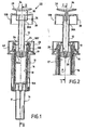
- the device shown in the figures comprises a syringe which has a syringe body 10, a needle 11 and a piston 12 which can slide in this body for injection.
- the piston 12 is in its position of waiting for injection, in which its front end 12A is located towards the rear end 10B, remote from the needle, of the syringe body 10.
- the device is shown before the injection and, in a manner known per se, the needle 11 is protected by a protective cap 14 which is attached to the front end 10A of the syringe body 10.
- the device also comprises security means which comprise a protective sheath 16.
- this protective sheath 16 is in a waiting position, in which it is arranged around the syringe body 10; it is the injection configuration.
- this sheath relative to the syringe body 10 has been triggered, and it is seen that the sleeve 16 protrudes beyond the front end 10A of the syringe body so that the needle 11 extends inside the sheath; it's the protection configuration.
- the protection means are similar to those disclosed in the document FR 2 801 795 and, at the end of injection, it is the sheath 16 which moves relative to the syringe body to advance and come to be placed around the needle.
- the syringe body is disposed in a support sleeve 18 inside which the protective sheath 16 is retracted in the waiting position, being disposed in an annular space formed between the syringe body and this sheath. support.
- the rear end of the support sleeve 18 is formed by an end portion 20 which makes it possible to retain the syringe body in a fixed manner inside the support sleeve by the collar 10B 'of this rear end. More precisely, as we see on the figure 3 the portion 20 has radial wall members 22 forming rearwardly facing shoulder portions on which the collar 10B 'rests so as to prevent the syringe body from moving forward relative to the support sleeve .
- the portion 20 also comprises retaining tongues 24 which are resilient and radially deviate during the insertion of the flange 10B 'in the portion 20 to the shoulder portions 22, before returning to their initial position to retain this flange vis-à-vis a movement backwards.
- the rear end of the sheath 18 has, in its zone of connection with the portion 20, a rearward-facing inner shoulder 19 on which, in the injection configuration, resilient tabs 17 of the rear end the protective sheath 16 are hooked to prevent the movement of the protective sheath forward.
- Part 20 has actuating tabs 26 which, as seen on the figure 2 are located opposite legs 17.
- the protective sheath 16 In the vicinity of its rear end, the protective sheath 16 has a recess 17 'forming a rearward-facing inner shoulder for the front end of a spring 28.
- the rear end of this spring rests against the front face of the wall elements that constitute the shoulder portions 22 previously mentioned.
- the spring 28 is compressed.
- the rear head 12B of the piston 12 has a skirt 30 which constitutes a trigger member for passing the device into its protective configuration.
- the front end 30A of this skirt cooperates with the elastic tabs 26 to push the latter radially inwards, that is to say say to the axis A of the device, so that these tabs push the tabs 17 of the protective sleeve also inwardly. Then, the latter is no longer retained by the shoulder 19 and can advance under the effect of the force exerted by the spring 28 to reach the position shown in FIG. figure 6 wherein the device is in its protection configuration.
- the security means that have just been described correspond to those defined in the document FR 2 801 795 and the syringe body is stationary, while it is the protective sheath that advances relative thereto to obtain the protection configuration.
- the invention also applies to inverse devices, in which the syringe body moves back relative to the protective sheath to define the protection configuration.
- the device of the invention comprises means for defining two distinct situations of end of injection stroke, one in which the triggering of the injection configuration is not achieved, and the other in which this triggering is realized.
- the trigger member constituted by the skirt 30 is integral with the displacement of the piston 12 and the first and second injection end-of-stroke situations respectively correspond to a first and a second piston injection end-of-stroke position. .
- the first end of injection stroke position is represented on the Figures 4 and 5 and it is seen that the front end 12A of the piston 12 does not quite come into contact with the front end 10A of the syringe body.
- the space 32 which is delimited between these two ends is exaggerated on the drawing for the perfect understanding of the invention.
- this space has a very small volume and it can even be expected that, in this first end position, the front end of the piston comes into contact with the wall formed at the front end 10A of the syringe body, because this front end of the piston E is formed by a flexible piece, for example elastomer, whose deformability allows it to be slightly compressed to, in the second end-of-stroke configuration, allow the piston to advance further forward for occupy his second end position as shown in the figure 6 .
- a flexible piece for example elastomer
- the device comprises an inhibitory organ 34 which, on the Figures 1 to 5 , in its inhibiting position in which it is connected to the head 12B of the piston 12.
- the inhibiting member 34 is formed by a head piece 34 which is attached to the head 12B of the piston in its position of inhibition and which can be separated from this head to allow the obtaining of the second position of piston injection end of stroke. More precisely, in its position of inhibition represented on the Figures 1 to 5 , the inhibiting member 34 passes through the piston head which, for this purpose, has a slot 36. It is a longitudinal portion of the piece 34, formed by a tenon or a wall element 38, which passes through this slot.
- the front end 38A of the post or this wall element is therefore in an interior space of the piston head formed between the inner face of the skirt 30 and the piston rod.
- the tenon 38 advances toward the end of the piston opposite its head 12B, further than the skirt 30.
- the inhibiting member could cooperate in abutment with another element of the device than the rear end of the syringe body. It may in fact be any fixed element with respect to the syringe body, in particular any suitable part of the outer sheath 18 or of the part 20.
- the interior space of the portion 20 forms a housing 40 in which, as seen on the figure 6 , the piston head 12B is substantially retracted into the second end-of-stroke injection position, so that the piston is no longer or practically more usable.
- the piston head protrudes out of this housing. It thus provides the user with a plug that allows the piston to be pulled backwards to prepare the device for injection.
- the trigger member is formed by the skirt 52 of a cap 50 which is arranged around the head 12B of the piston and which is movable relative thereto.
- FIG. 7 shows the cap 50 in its position unsuitable for triggering, in which it is moved backward relative to the head 12B.
- the front end 52A of the skirt 52 does not reach until contact with the actuating tabs 26 previously mentioned at the end of the injection stroke.
- an actuating tab 26 is shown in phantom on the Figures 7 and 8 although it is not in the plane of section of these figures.
- the cap 50 is advanced on the head 12B of the piston so that its skirt 52 can, at the end of the injection stroke, cooperate with the tongues 26 by its front end as does the skirt 30 of the previous embodiment on the figure 6 .
- the sliding of the trigger member 50 relative to the piston 12 comprises a hard point for maintaining the trigger member in its position unfit for triggering.
- the inner wall of the skirt 52 has a clipping rib 53 which, in the position unfit for triggering the figure 7 is retained between two ribs 54A and 54B formed on the outer wall of the skirt 30 of the head 12B.
- the rear end wall thereof has a central opening 56 through which the user can insert a finger to support directly on the piston head 12B.
- the piston can be brought back by manipulating it by the cap 50, which is retained by the rib 54B vis-à-vis a rearward displacement.
- the outer wall of the skirt 30 has another rib 56A, which is located near its front end and in front of which is disposed the rib 53 of the skirt 52 when the cap 50 is in its position capable of triggering .
- the cap 50 which is unfit for triggering, it is the front end 30A of the skirt 30 of the piston head which prevents this piston from being moved forward beyond its first end position represented in the figure 7 cooperating in abutment with a fixed element relative to the syringe body, in this case constituted by the rear ends of the tongues 24.
- the means (inhibitor member 54 or trigger member 50) which, associated with the piston, make it possible to avoid a systematic passage in the protective configuration at the end of the injection are reported on the piston head and may be separated or be moved relative to this head to allow obtaining the second end of injection stroke situation.
- These two examples are external means to the piston.
- an internal member of the piston for example passing through the inside of the hollow rod of the latter, in order to cooperate or not in abutment with a fixed element of the device, for example the collar of the syringe or an element in solidarity with Part 20.
Landscapes
- Health & Medical Sciences (AREA)
- Engineering & Computer Science (AREA)
- Heart & Thoracic Surgery (AREA)
- Vascular Medicine (AREA)
- Anesthesiology (AREA)
- Biomedical Technology (AREA)
- Environmental & Geological Engineering (AREA)
- Hematology (AREA)
- Life Sciences & Earth Sciences (AREA)
- Animal Behavior & Ethology (AREA)
- General Health & Medical Sciences (AREA)
- Public Health (AREA)
- Veterinary Medicine (AREA)
- Infusion, Injection, And Reservoir Apparatuses (AREA)
Claims (10)
- Gesicherte Injektionsvorrichtung, umfassend eine Spritze mit einem Spritzenkörper (10), einer Nadel (11) und einem Kolben (12), der geeignet ist, für eine Injektion in diesem Körper bewegt zu werden, sowie Sicherheitsmittel, die eine Schutzhülse (16) umfassen, wobei der Spritzenkörper und die Schutzhülse (16) zwischen einer Injektionsausführung, in der die Nadel (11) aus der Schutzhülse (16), welche um den Spritzenkörper (10) herum angeordnet ist, hinausragt, und einer Schutzausführung, in der die Nadel innerhalb der Hülse verläuft, zueinander verschieblich sind, wobei die Vorrichtung ein Auslöseorgan (30, 52) umfaßt, das mit dem Betätigungskopf (12B) des Kolbens (12) fest verbunden und geeignet ist, den Übergang von der Injektionsausführung in die Schutzausführung in der Injektionsendstellung zu bewirken, wobei die Vorrichtung ein Hemmorgan (34, 50) umfaßt, das geeignet ist, eine Ausgangshemmposition einzunehmen, in der das Hemmorgan (34, 50) eine erste Injektionsendstellung des Kolbens definiert, in welcher das Auslöseorgan (30, 52) nicht in der Lage ist, den Übergang von der Injektionsausführung in die Schutzausführung zu bewirken, sowie von dem Kolben (12) getrennt oder ihm gegenüber bewegt zu werden, um eine zweite Injektionsendstellung des Kolbens zu ermöglichen, in der das Auslöseorgan (30, 52) in der Lage ist, den Übergang von der Injektionsausführung in die Schutzausführung zu bewirken,
dadurch gekennzeichnet, daß das Hemmorgan (34, 50) in seiner Ausgangshemmposition auf den Betätigungskopf (12B) des Kolbens (12) aufgesetzt ist, so daß der Benutzer auf das Hemmorgan (34, 50) drückt, um den Kolben (12) bis zu seiner ersten Injektionsendstellung zu bewegen, und daß der Benutzer für den Übergang von der Hemmposition in die zweite Position, wobei das Hemmorgan (34, 50) gegenüber dem Kolben (12) bewegt oder hiervon getrennt wird, auf den Betätigungskopf (12B) des Kolbens drückt. - Vorrichtung nach Anspruch 1, dadurch gekennzeichnet, daß das Hemmorgan (34) in seiner Hemmposition den Kopf (12B) des Kolbens (12) durchgreift.
- Vorrichtung nach Anspruch 2, dadurch gekennzeichnet, daß ein Längsabschnitt des Hemmorgans (34), der von einem Zapfen oder von einem Wandelement (38) gebildet ist, den Betätigungskopf (12B) des Kolbens durch einen Schlitz (36) durchgreift.
- Vorrichtung nach einem der Ansprüche 1 bis 3, dadurch gekennzeichnet, daß sie Anschlagmittel (38A, 10B) umfaßt, die geeignet sind, in Gebrauch gesetzt zu werden, um die erste Injektionsendstellung zu definieren, und außer Gebrauch gesetzt zu werden, um das Erreichen der zweiten Injektionsendstellung zu ermöglichen.
- Vorrichtung nach Anspruch 4, dadurch gekennzeichnet, daß das Hemmorgan (34) in seiner Hemmposition geeignet ist, mit einem Element (10B) der Vorrichtung, das gegenüber dem Spritzenkörper (10) fest ist, anschlagend zusammenzuwirken, um die erste Injektionsendstellung zu definieren.
- Vorrichtung nach einem der Ansprüche 1 bis 5, dadurch gekennzeichnet, daß sie eine Aufnahme (40) umfaßt, in welcher der Kopf (12B) des Kolbens (12) in der zweiten Injektionsendstellung im wesentlichen eingezogen ist, und daß in der ersten Injektionsendstellung der Kopf des Kolbens aus dieser Aufnahme hinausragt, um eine Greifstelle zu bieten, die ermöglicht, den Kolben -ihn von der Nadel entfernend- zu ziehen.
- Vorrichtung nach Anspruch 1, dadurch gekennzeichnet, daß das Hemmorgan eine Kappe (50) ist, von der ein Mantelteil (52) das Auslöseorgan bildet und die gegenüber dem Kolben (12) axial beweglich ist, wobei die für das Auslösen geeignete Position gegenüber der für das Auslösen ungeeigneten Position in Richtung des der Nadel zugewandten Endes (12A) des Kolbens (12) versetzt ist.
- Vorrichtung nach Anspruch 7, dadurch gekennzeichnet, daß das Hemmorgan Mittel (53, 54A, 54B) umfaßt, um eine schwergängige Stelle beim Verschieben der Kappe (50) gegenüber dem Kolben (12) zu definieren, um das Auslöseorgan (52) in seiner für das Auslösen ungeeigneten Position zu halten.
- Vorrichtung nach einem der Ansprüche 1 bis 8, dadurch gekennzeichnet, daß das Auslöseorgan (30, 52) von einem Mantel gebildet ist, der geeignet ist, über Laschen (26) mit elastischen Laschen (17) der Schutzhülse (16) zusammenzuwirken, um den Übergang von der Injektionsausführung in die Schutzausführung zu bewirken.
- Vorrichtung nach einem der Ansprüche 1 bis 9, dadurch gekennzeichnet, daß die Schutzhülse (16) zwischen dem Spritzenkörper (10) und einer Traghülse (18) angeordnet ist.
Applications Claiming Priority (2)
| Application Number | Priority Date | Filing Date | Title |
|---|---|---|---|
| FR0312327A FR2861310B1 (fr) | 2003-10-22 | 2003-10-22 | Dispositif de seringue d'injection securise |
| PCT/FR2004/002654 WO2005039678A2 (fr) | 2003-10-22 | 2004-10-18 | Dispositif de seringue d'injection securise |
Publications (2)
| Publication Number | Publication Date |
|---|---|
| EP1682207A2 EP1682207A2 (de) | 2006-07-26 |
| EP1682207B1 true EP1682207B1 (de) | 2012-07-18 |
Family
ID=34400692
Family Applications (1)
| Application Number | Title | Priority Date | Filing Date |
|---|---|---|---|
| EP04817285A Active EP1682207B1 (de) | 2003-10-22 | 2004-10-18 | Geschützte injektionsspritzenvorrichtung |
Country Status (5)
| Country | Link |
|---|---|
| US (1) | US9314575B2 (de) |
| EP (1) | EP1682207B1 (de) |
| JP (1) | JP2007508883A (de) |
| FR (1) | FR2861310B1 (de) |
| WO (1) | WO2005039678A2 (de) |
Families Citing this family (69)
| Publication number | Priority date | Publication date | Assignee | Title |
|---|---|---|---|---|
| US8562583B2 (en) | 2002-03-26 | 2013-10-22 | Carmel Pharma Ab | Method and assembly for fluid transfer and drug containment in an infusion system |
| US7867215B2 (en) | 2002-04-17 | 2011-01-11 | Carmel Pharma Ab | Method and device for fluid transfer in an infusion system |
| SE523001C2 (sv) | 2002-07-09 | 2004-03-23 | Carmel Pharma Ab | En kopplingsdel, en koppling, en infusionspåse, en infusionsanordning och ett förfarande för överföring av medicinska substanser |
| EP1590024B1 (de) | 2003-01-21 | 2016-04-27 | Carmel Pharma AB | Nadel zum durchstechen einer membran |
| FR2852851B1 (fr) * | 2003-03-25 | 2006-01-06 | Sedat | Dispositif de protection d'aiguille destine a une seringue, et dispositif d'injection comprenant une seringue et ce dispositif de protection |
| IL157981A (en) | 2003-09-17 | 2014-01-30 | Elcam Medical Agricultural Cooperative Ass Ltd | Auto injector |
| FR2861310B1 (fr) | 2003-10-22 | 2006-09-22 | Plastef Investissements | Dispositif de seringue d'injection securise |
| GB2414399B (en) | 2004-05-28 | 2008-12-31 | Cilag Ag Int | Injection device |
| GB2414403B (en) | 2004-05-28 | 2009-01-07 | Cilag Ag Int | Injection device |
| GB2414775B (en) | 2004-05-28 | 2008-05-21 | Cilag Ag Int | Releasable coupling and injection device |
| GB2414401B (en) | 2004-05-28 | 2009-06-17 | Cilag Ag Int | Injection device |
| GB2414409B (en) | 2004-05-28 | 2009-11-18 | Cilag Ag Int | Injection device |
| GB2414402B (en) | 2004-05-28 | 2009-04-22 | Cilag Ag Int | Injection device |
| GB2414406B (en) | 2004-05-28 | 2009-03-18 | Cilag Ag Int | Injection device |
| GB2414400B (en) | 2004-05-28 | 2009-01-14 | Cilag Ag Int | Injection device |
| US7294119B2 (en) | 2004-06-10 | 2007-11-13 | Safety Syringes, Inc. | Passive delivery system diluents mixing and delivery |
| GB2424838B (en) | 2005-04-06 | 2011-02-23 | Cilag Ag Int | Injection device (adaptable drive) |
| GB2425062B (en) | 2005-04-06 | 2010-07-21 | Cilag Ag Int | Injection device |
| GB2424835B (en) | 2005-04-06 | 2010-06-09 | Cilag Ag Int | Injection device (modified trigger) |
| GB2424836B (en) | 2005-04-06 | 2010-09-22 | Cilag Ag Int | Injection device (bayonet cap removal) |
| GB2427826B (en) | 2005-04-06 | 2010-08-25 | Cilag Ag Int | Injection device comprising a locking mechanism associated with integrally formed biasing means |
| DE602005018480D1 (de) | 2005-08-30 | 2010-02-04 | Cilag Gmbh Int | Nadelvorrichtung für eine vorgefüllte Spritze |
| US20110098656A1 (en) | 2005-09-27 | 2011-04-28 | Burnell Rosie L | Auto-injection device with needle protecting cap having outer and inner sleeves |
| GB2438590B (en) | 2006-06-01 | 2011-02-09 | Cilag Gmbh Int | Injection device |
| GB2438591B (en) † | 2006-06-01 | 2011-07-13 | Cilag Gmbh Int | Injection device |
| GB2438593B (en) | 2006-06-01 | 2011-03-30 | Cilag Gmbh Int | Injection device (cap removal feature) |
| EP2029202B1 (de) * | 2006-06-16 | 2013-12-25 | Marc Brunel | Sicherheitsvorrichtung zur injektion eines medizinprodukts, z.b. eines lyophiliserten produkts |
| FR2905873B1 (fr) * | 2006-09-20 | 2008-11-14 | Becton Dickinson France Soc Pa | Dispositif d'injection prevenant le recul du piston lors du deploiement du systeme de securite |
| US7942860B2 (en) | 2007-03-16 | 2011-05-17 | Carmel Pharma Ab | Piercing member protection device |
| US7975733B2 (en) | 2007-05-08 | 2011-07-12 | Carmel Pharma Ab | Fluid transfer device |
| US9044378B2 (en) * | 2007-05-31 | 2015-06-02 | Safety Syringes, Inc. | Anti-needle stick safety device or system for use with drugs requiring reconstitution |
| US8622985B2 (en) | 2007-06-13 | 2014-01-07 | Carmel Pharma Ab | Arrangement for use with a medical device |
| US8657803B2 (en) | 2007-06-13 | 2014-02-25 | Carmel Pharma Ab | Device for providing fluid to a receptacle |
| US8029747B2 (en) | 2007-06-13 | 2011-10-04 | Carmel Pharma Ab | Pressure equalizing device, receptacle and method |
| US10398834B2 (en) | 2007-08-30 | 2019-09-03 | Carmel Pharma Ab | Device, sealing member and fluid container |
| US8287513B2 (en) | 2007-09-11 | 2012-10-16 | Carmel Pharma Ab | Piercing member protection device |
| JP5329546B2 (ja) | 2007-09-17 | 2013-10-30 | カルメル ファルマ アクチボラゲット | バッグコネクタ |
| FR2922456B1 (fr) | 2007-10-23 | 2009-12-11 | Plastef Investissements | Dispositif de securite pour une seringue. |
| FR2922455B1 (fr) | 2007-10-23 | 2010-10-29 | Plastef Investissements | Dispositif de seringue comprenant un corps de seringue et un manchon de support. |
| JP5502743B2 (ja) * | 2007-11-21 | 2014-05-28 | ベクトン・ディキンソン・フランス・エス.エー.エス. | 安全システムが展開されたときにピストンの復帰を妨げる注射器具 |
| US8105292B2 (en) * | 2008-02-11 | 2012-01-31 | Safety Syringes, Inc. | Reconstitution means for safety device |
| GB2461086B (en) | 2008-06-19 | 2012-12-05 | Cilag Gmbh Int | Injection device |
| GB2461087B (en) | 2008-06-19 | 2012-09-26 | Cilag Gmbh Int | Injection device |
| GB2461089B (en) | 2008-06-19 | 2012-09-19 | Cilag Gmbh Int | Injection device |
| GB2461085B (en) | 2008-06-19 | 2012-08-29 | Cilag Gmbh Int | Injection device |
| GB2461084B (en) | 2008-06-19 | 2012-09-26 | Cilag Gmbh Int | Fluid transfer assembly |
| US8075550B2 (en) * | 2008-07-01 | 2011-12-13 | Carmel Pharma Ab | Piercing member protection device |
| US8790330B2 (en) | 2008-12-15 | 2014-07-29 | Carmel Pharma Ab | Connection arrangement and method for connecting a medical device to the improved connection arrangement |
| US8523838B2 (en) | 2008-12-15 | 2013-09-03 | Carmel Pharma Ab | Connector device |
| JP4361962B1 (ja) | 2009-01-30 | 2009-11-11 | 株式会社アルテ | 容器兼用注射器 |
| JP5551764B2 (ja) * | 2009-05-07 | 2014-07-16 | ベクトン ディキンソン フランス | フランジ付き容器のための支持スリーブ |
| USD637713S1 (en) | 2009-11-20 | 2011-05-10 | Carmel Pharma Ab | Medical device adaptor |
| US8480646B2 (en) | 2009-11-20 | 2013-07-09 | Carmel Pharma Ab | Medical device connector |
| US8920385B2 (en) | 2010-05-05 | 2014-12-30 | Safety Syringes, Inc. | Extended finger flange for syringe systems |
| US9168203B2 (en) | 2010-05-21 | 2015-10-27 | Carmel Pharma Ab | Connectors for fluid containers |
| US8162013B2 (en) | 2010-05-21 | 2012-04-24 | Tobias Rosenquist | Connectors for fluid containers |
| US9022990B2 (en) | 2011-04-04 | 2015-05-05 | Tech Group Europe Limited | Needle safety shield |
| US9050416B2 (en) | 2012-11-01 | 2015-06-09 | Tech Group Europe Limited | Needle Safety device with floating ring |
| EP2752211A1 (de) * | 2013-01-07 | 2014-07-09 | F. Hoffmann-La Roche Ltd. | Sicherheitsvorrichtung für eine Injektionsspritze |
| GB2515032A (en) | 2013-06-11 | 2014-12-17 | Cilag Gmbh Int | Guide for an injection device |
| GB2515038A (en) | 2013-06-11 | 2014-12-17 | Cilag Gmbh Int | Injection device |
| GB2517896B (en) | 2013-06-11 | 2015-07-08 | Cilag Gmbh Int | Injection device |
| GB2515039B (en) | 2013-06-11 | 2015-05-27 | Cilag Gmbh Int | Injection Device |
| RU2695560C2 (ru) * | 2013-08-29 | 2019-07-24 | Санофи | Предохранительное устройство для резервуара для лекарственного препарата |
| JP5881762B2 (ja) * | 2014-03-13 | 2016-03-09 | ベクトン・ディキンソン・フランス・エス.エー.エス. | 安全システムが展開されたときにピストンの復帰を妨げる注射器具 |
| USD765838S1 (en) | 2015-03-26 | 2016-09-06 | Tech Group Europe Limited | Syringe retention clip |
| FR3038840B1 (fr) * | 2015-07-16 | 2017-07-21 | Nemera La Verpilliere | Dispositif de securite pour une seringue d'injection. |
| CN108290011A (zh) * | 2015-11-27 | 2018-07-17 | 赛诺菲-安万特德国有限公司 | 具有针护罩移除机构的注射装置 |
| JP1691374S (de) | 2019-11-01 | 2021-08-02 |
Family Cites Families (115)
| Publication number | Priority date | Publication date | Assignee | Title |
|---|---|---|---|---|
| US1921034A (en) | 1931-10-31 | 1933-08-08 | Marche Norman O La | Syringe container and ejector |
| US3880163A (en) | 1973-10-26 | 1975-04-29 | Jack H Ritterskamp | Medicinal syringe actuating device |
| US4631057A (en) | 1985-12-17 | 1986-12-23 | Dolores A. Smith | Shielded needle |
| US4723943A (en) | 1986-12-31 | 1988-02-09 | Montana Deaconess Medical Center | Sheathed syringe |
| US4832696A (en) | 1987-03-05 | 1989-05-23 | Luther Medical Products, Inc. | Assembly of needle and protector |
| US4828548A (en) | 1987-03-16 | 1989-05-09 | Walter Gregory W | Safety catheter |
| US4747831A (en) | 1987-04-29 | 1988-05-31 | Phase Medical, Inc. | Cannula insertion set with safety retracting needle |
| US4927416A (en) | 1987-12-02 | 1990-05-22 | National Medical Device Corporation | User-protective hypodermic syringe holder |
| US4887998A (en) | 1987-12-14 | 1989-12-19 | Martin Catherine L | Hypodermic needle guard |
| US4931040A (en) | 1988-04-13 | 1990-06-05 | Habley Medical Technology | Safety syringe having a combination needle cannula and articulating hub for retracting said cannula into a medication carpule |
| US4923446A (en) | 1988-04-14 | 1990-05-08 | Page Mary J | Shield for devices capable of penetrating skin |
| US4871355A (en) | 1988-05-17 | 1989-10-03 | Steven Kikkawa | Injury resistant needle and blood collection tube holder |
| US5026349A (en) | 1988-10-05 | 1991-06-25 | Autoject Systems Inc. | Liquid medicament injector system |
| US4911693A (en) | 1988-10-17 | 1990-03-27 | Paris Frassetti R | Hypodermic syringe needle guard |
| US4929237A (en) | 1988-11-07 | 1990-05-29 | David Medway | Hypodermic needle protection device |
| US5858000A (en) | 1988-12-14 | 1999-01-12 | Inviro Medical Devices Ltd. | Safety syringe needle device with interchangeable and retractable needle platform |
| US4923447A (en) | 1989-02-17 | 1990-05-08 | Morgan Michael W | Syringe assembly |
| US5141500A (en) | 1989-03-02 | 1992-08-25 | Lawrence W. Hake | Hypodermic needle guard |
| US4966592A (en) | 1989-05-05 | 1990-10-30 | Burns Cameron A | Protective sleeve for hypodermic needle |
| DE69024815T2 (de) * | 1989-09-18 | 1996-05-23 | Robb Pascal Patent Pty Ltd | Spritze |
| US4986819A (en) | 1989-09-26 | 1991-01-22 | Daniel Sobel | Pressure sensitive needle guard |
| FR2653667B1 (fr) * | 1989-11-02 | 1992-03-06 | Floquet Nicole | Seringue a usage unique - non reutilisable - avec protection automatique de l'aiguille en fin d'injection et verrouillage. |
| US5558651A (en) | 1990-04-20 | 1996-09-24 | Becton Dickinson And Company | Apparatus and method for a needle tip cover |
| US5112307A (en) | 1990-04-24 | 1992-05-12 | Habley Medical Technology Corp. | Dental syringe having a medication filled carpule and an automatically-detaching piston stem |
| US5279581A (en) | 1990-05-09 | 1994-01-18 | Firth John R | Disposable self-shielding hypodermic syringe |
| US5108378A (en) | 1990-05-09 | 1992-04-28 | Safety Syringes, Inc. | Disposable self-shielding hypodermic syringe |
| EP0467173B1 (de) * | 1990-07-19 | 1995-11-08 | Nardino Righi | Sicherheitsspritze zum einmaligen Gebrauch |
| US5324272A (en) | 1990-07-27 | 1994-06-28 | Sterling Winthrop Inc. | Multiple-celled safety package, needle guard and safe disposal module for prefilled medication cartridge |
| US5360410A (en) | 1991-01-16 | 1994-11-01 | Senetek Plc | Safety syringe for mixing two-component medicaments |
| US5306258A (en) | 1991-04-03 | 1994-04-26 | Fuente Ricardo L De | Safety syringe and method of using same |
| US5106379A (en) | 1991-04-09 | 1992-04-21 | Leap E Jack | Syringe shielding assembly |
| US5201708A (en) | 1992-02-03 | 1993-04-13 | Timothy A. Kershenstine | Self-locking safety syringe |
| US5261880A (en) | 1992-03-10 | 1993-11-16 | Injectimed, Inc. | Single use syringes with second use lockout |
| US5201720A (en) | 1992-04-21 | 1993-04-13 | Joseph Borgia | Syringe holding and ejecting assembly |
| GB9212742D0 (en) | 1992-06-16 | 1992-07-29 | Sterimatic Holdings Ltd | Syringe or blood collection system |
| US5267972A (en) | 1992-07-20 | 1993-12-07 | Anderson Wayne W | Hypodermic syringe with needle guard |
| US5411487A (en) | 1992-12-07 | 1995-05-02 | Castagna; John F. | Hypodermic syringe with automatic needle cover |
| US5346480A (en) | 1992-12-14 | 1994-09-13 | Q-Med, Inc. | Syringe with retractable needle |
| US5803918A (en) | 1993-05-06 | 1998-09-08 | Becton Dickinson And Company | Syringe for medicinal purposes |
| DE9321547U1 (de) | 1993-05-06 | 1999-07-15 | Becton Dickinson Co | Spritze für medzinische Zwecke |
| US5338311A (en) | 1993-08-23 | 1994-08-16 | Mahurkar Sakharam D | Hypodermic needle assembly |
| US5385551A (en) * | 1993-09-22 | 1995-01-31 | Shaw; Thomas J. | Nonreusable medical device with front retraction |
| GB9323447D0 (en) | 1993-11-13 | 1994-01-05 | Seldoren Ltd | Syringes |
| FR2733687B1 (fr) | 1995-05-04 | 1997-10-03 | Brunel Marc | Procede de fabrication d'un dispositif d'injection du type pre-rempli renfermant une dose de liquide a injecter, et dispositif d'injection realise |
| ZA964503B (en) | 1995-06-02 | 1996-12-09 | Louis Hubert Jacobs | Medical apparatus |
| US5591138A (en) | 1995-08-10 | 1997-01-07 | Vaillancourt; Vincent L. | Protected needle assembly |
| US5817064A (en) | 1995-10-23 | 1998-10-06 | American Home Products Corporation | Syringe needle guard |
| US5997513A (en) | 1995-11-22 | 1999-12-07 | Smith; Jerry A. | Syringe cover cooperating with needle cover |
| US5913846A (en) | 1996-06-13 | 1999-06-22 | Becton, Dickinson And Company | Shielded needle assembly |
| FR2757067B1 (fr) | 1996-12-17 | 1999-07-16 | Sedat | Seringue d'injection a protecteur d'aiguille deplacable |
| US5891104A (en) | 1997-01-10 | 1999-04-06 | Univec, Inc. | Hypodermic syringe having retractable needle |
| ATE252925T1 (de) | 1997-02-12 | 2003-11-15 | Sergio Restelli | Einwegsicherheitsspritze |
| US6159184A (en) | 1997-03-10 | 2000-12-12 | Safety Syringes, Inc. | Disposable self-shielding unit dose syringe guard |
| FR2762790B1 (fr) | 1997-05-05 | 1999-08-13 | Stephane Dreystadt | Systeme d'injection a longueur d'aiguille variable |
| US6569115B1 (en) | 1997-08-28 | 2003-05-27 | Mdc Investment Holdings, Inc. | Pre-filled retractable needle injection device |
| US5951526A (en) | 1997-09-24 | 1999-09-14 | Korisch; Marina | Syringe holder with integral dose divider |
| IT1304761B1 (it) * | 1998-01-20 | 2001-03-29 | Nardino Righi | Siringa monouso di sicurezza. |
| US6616639B2 (en) | 1998-04-17 | 2003-09-09 | Becton, Dickinson And Company | Safety shield system for syringes |
| US6319233B1 (en) | 1998-04-17 | 2001-11-20 | Becton, Dickinson And Company | Safety shield system for prefilled syringes |
| US6719730B2 (en) | 1998-04-17 | 2004-04-13 | Becton, Dickinson And Company | Safety shield system for prefilled syringes |
| US7455661B2 (en) | 1998-04-17 | 2008-11-25 | Becton, Dickinson And Company | Safety shield system for prefilled syringe |
| US6679864B2 (en) | 1998-04-17 | 2004-01-20 | Becton Dickinson And Company | Safety shield system for prefilled syringes |
| FR2778853B1 (fr) | 1998-05-19 | 2000-12-22 | Sedat | Seringue d'injection a protecteur d'aiguille charge par un ressort |
| FR2794650B1 (fr) | 1999-06-10 | 2001-09-14 | Marc Brunel | Dispositif d'injection a usage unique |
| US20010031949A1 (en) | 1999-06-18 | 2001-10-18 | Asbaghi Hooman A. | Protective device for a prefilled injection syringe |
| US6379336B1 (en) | 1999-06-18 | 2002-04-30 | Hooman A. Asbaghi | Protective device for injection or aspiration needle |
| DE19929325A1 (de) | 1999-06-26 | 2001-01-18 | Vetter & Co Apotheker | Spritze für medizinische Zwecke |
| FR2799376B1 (fr) | 1999-10-07 | 2002-01-18 | Marc Brunel | Dispositif d'injection a usage unique |
| FR2799976B1 (fr) | 1999-10-26 | 2002-06-21 | Plastic Omnium Cie | Dispositif de securite pour seringue d'injection |
| US7029461B2 (en) | 1999-11-04 | 2006-04-18 | Tyco Healthcare Group Lp | Safety shield for medical needles |
| US7198618B2 (en) | 1999-11-04 | 2007-04-03 | Tyco Healthcare Group Lp | Safety shield for medical needles |
| WO2001037898A2 (en) | 1999-11-29 | 2001-05-31 | Mdc Investment Holdings, Inc. | Combination safety needle assembly and medical apparatus |
| FR2801795B1 (fr) | 1999-12-07 | 2002-07-05 | Plastef Investissements | Dispositif de support de securite pour une seringue et ensemble d'un tel dispositif et d'une seringue |
| DE60015805T2 (de) | 2000-01-27 | 2005-11-17 | Biomd Ltd., Perth | Einwegspritze |
| GB0003790D0 (en) * | 2000-02-18 | 2000-04-05 | Astrazeneca Uk Ltd | Medical device |
| US6171284B1 (en) | 2000-03-15 | 2001-01-09 | Wang-Hsiang Kao | Syringe needle cover structure |
| US6475194B2 (en) | 2000-04-05 | 2002-11-05 | Gem Plastics, Inc. | Safety syringe |
| DE10018827A1 (de) | 2000-04-15 | 2001-10-25 | Vetter & Co Apotheker | Spritze für medizinische Zwecke |
| US6613022B1 (en) | 2000-05-05 | 2003-09-02 | Safety Syringes, Inc. | Passive needle guard for syringes |
| US6623459B1 (en) | 2000-05-05 | 2003-09-23 | Safety Syringes, Inc. | Passive needle guard for syringes |
| US6416323B1 (en) | 2000-05-11 | 2002-07-09 | Safety Syringes, Inc. | Aspirating dental syringe with needle shield |
| BR0110933B1 (pt) | 2000-05-18 | 2009-08-11 | seringa controlada eletricamente ou computadorizada para distribuir um material fluido. | |
| US6547764B2 (en) | 2000-05-31 | 2003-04-15 | Novo Nordisk A/S | Double pointed injection needle |
| AU8466901A (en) | 2000-07-28 | 2002-02-13 | Mdc Invest Holdings Inc | Retractable needle medical device for injecting fluid from a pre-filled cartridge |
| US7144389B2 (en) | 2001-03-14 | 2006-12-05 | Tyco Healthcare Group, Lp | Safety shield for medical needles |
| AUPR373001A0 (en) * | 2001-03-14 | 2001-04-12 | Glenord Pty Ltd | Improved non-reusable syringe |
| GB0110443D0 (en) | 2001-04-28 | 2001-06-20 | Owen Mumford Ltd | Improvements relating to syringe holders |
| FR2830764B1 (fr) | 2001-10-15 | 2004-07-23 | Plastic Omnium Cie | Dispositif de securite pour une seringue |
| FR2830765B1 (fr) | 2001-10-15 | 2004-07-23 | Plastic Omnium Cie | Dispositif de securite pour une seringue |
| FR2835753B1 (fr) | 2002-02-11 | 2004-10-29 | Plastef Investissements | Dispositif de support de securite pour une seringue et ensemble d'un tel dispositif et d'une seringue |
| FR2837107B1 (fr) | 2002-03-18 | 2005-02-25 | Sedat | Dispositif de protection d'aiguille destine a une seringue, et dispositif d'injection comprenant une seringue et ce dispositif de protection |
| US6976976B2 (en) | 2002-03-27 | 2005-12-20 | Safety Syringes, Inc. | Syringe with needle guard injection device |
| US20030187401A1 (en) | 2002-03-27 | 2003-10-02 | Safety Syringes, Inc. | Syringe with integral safety system |
| US7004929B2 (en) | 2002-03-29 | 2006-02-28 | Mdc Investment Holdings, Inc. | Safety pre-filled cartridge injector |
| AU2002350135A1 (en) | 2002-11-06 | 2004-06-03 | Becton, Dickinson And Company | Passive safety shield system for injection devices |
| ATE434457T1 (de) * | 2002-11-18 | 2009-07-15 | Sergio Restelli | Schutzvorrichtung befestigbar an einer standardspritze um sie in eine sicherheitsspritze umzuwandeln |
| US7300421B1 (en) | 2002-11-26 | 2007-11-27 | Suzanne L. Lowry | Safety syringe and safety syringe adapter |
| US7544180B2 (en) | 2003-02-27 | 2009-06-09 | B. Braun Melsungen Ag | Safety syringes |
| FR2852851B1 (fr) | 2003-03-25 | 2006-01-06 | Sedat | Dispositif de protection d'aiguille destine a une seringue, et dispositif d'injection comprenant une seringue et ce dispositif de protection |
| CN1226059C (zh) * | 2003-05-21 | 2005-11-09 | 江西洪达医疗器械集团有限公司 | 自毁式安全注射器 |
| FR2860162B1 (fr) | 2003-09-26 | 2006-06-02 | Becton Dickinson France | Dispositif de protection d'un appareil d'injection |
| FR2861310B1 (fr) | 2003-10-22 | 2006-09-22 | Plastef Investissements | Dispositif de seringue d'injection securise |
| FR2861598B1 (fr) | 2003-10-29 | 2006-06-16 | Plastef Investissements | Dispositif d'injection securise pour une seringue |
| US7635348B2 (en) | 2003-11-04 | 2009-12-22 | Meridian Medical Technologies, Inc. | Container for medicament automatic injector and automatic injector adapted therefor |
| FR2862542B1 (fr) | 2003-11-24 | 2006-11-17 | Sedat | Dispositif de protection d'aiguille destine a une carpule, et dispositif d'injection comprenant une carpule et ce dispositif de protection |
| FR2874505B1 (fr) | 2004-08-27 | 2007-06-08 | Sedat Sa | Dispositif d'injection comprenant une seringue |
| US7699814B2 (en) | 2005-05-17 | 2010-04-20 | Ralph Lande | Syringe sheath |
| CN101437561B (zh) | 2006-03-21 | 2011-09-28 | 泰科保健集团有限合伙公司 | 用于注射装置的被动式栓锁环安全防护装置 |
| GB0704351D0 (en) | 2007-03-07 | 2007-04-11 | Medical House Plc The | Improved autoinjector |
| FR2922457B1 (fr) | 2007-10-23 | 2010-10-29 | Plastef Investissements | Dispositif de seringue a capuchon de protection. |
| FR2922455B1 (fr) | 2007-10-23 | 2010-10-29 | Plastef Investissements | Dispositif de seringue comprenant un corps de seringue et un manchon de support. |
| FR2922456B1 (fr) | 2007-10-23 | 2009-12-11 | Plastef Investissements | Dispositif de securite pour une seringue. |
| GB0907534D0 (en) | 2009-05-01 | 2009-06-10 | Owen Mumford Ltd | Injection devices |
| US9022990B2 (en) | 2011-04-04 | 2015-05-05 | Tech Group Europe Limited | Needle safety shield |
| US9050416B2 (en) | 2012-11-01 | 2015-06-09 | Tech Group Europe Limited | Needle Safety device with floating ring |
-
2003
- 2003-10-22 FR FR0312327A patent/FR2861310B1/fr not_active Expired - Lifetime
-
2004
- 2004-10-18 EP EP04817285A patent/EP1682207B1/de active Active
- 2004-10-18 WO PCT/FR2004/002654 patent/WO2005039678A2/fr active Application Filing
- 2004-10-18 JP JP2006536115A patent/JP2007508883A/ja active Pending
- 2004-10-18 US US10/576,938 patent/US9314575B2/en active Active
Also Published As
| Publication number | Publication date |
|---|---|
| FR2861310A1 (fr) | 2005-04-29 |
| US20070179441A1 (en) | 2007-08-02 |
| WO2005039678A3 (fr) | 2005-07-28 |
| US9314575B2 (en) | 2016-04-19 |
| EP1682207A2 (de) | 2006-07-26 |
| FR2861310B1 (fr) | 2006-09-22 |
| WO2005039678A2 (fr) | 2005-05-06 |
| JP2007508883A (ja) | 2007-04-12 |
Similar Documents
| Publication | Publication Date | Title |
|---|---|---|
| EP1682207B1 (de) | Geschützte injektionsspritzenvorrichtung | |
| EP1436026B1 (de) | Sicherheitsvorrichtung für eine spritze | |
| EP1605997B1 (de) | Nadelschutzvorrichtung für eine spritze, und injektionsvorrichtung mit einer spritze und dieser nadelschutzvorrichtung | |
| EP1673121B1 (de) | Vorrichtung zum schutz einer injektionsvorrichtung | |
| EP1485153A2 (de) | Nadelschutzvorrichtung für eine spritze sowie injektionsvorrichtung bestehend aus einer spritze und dieser schutzvorrichtung | |
| EP2809525B1 (de) | Schreibinstrument mit einer einziehbaren spitze und einer schutzhülle | |
| FR2774294A1 (fr) | Dispositif d'injection automatique d'une dose de produit medicamenteux | |
| FR2884721A1 (fr) | Ensemble d'injection et dispositif d'assistance a l'injection | |
| WO2001041841A2 (fr) | Ensemble de securite pour une seringue | |
| EP1532997B1 (de) | Nadelschutzvorrichtung für eine Karpulle | |
| EP1985417B1 (de) | Sicherheitsmesser mit automatischem Rückzugsmechanismus der Schneide nach Beenden des Schneidevorgangs | |
| EP2200680B1 (de) | Sicherheitsgerät für eine spritze | |
| FR2930162A1 (fr) | Ensemble de protection d'aiguille comportant un element de verrouillage. | |
| EP1330279A1 (de) | Injektionsspritze mit einem verschiebbaren nadelschutz | |
| EP1224001B1 (de) | Hypodermatische wegwerfspritze mit arretierbarer schutzhülse | |
| EP3522957A1 (de) | Manuelle injektionsvorrichtung | |
| WO2005120861A1 (fr) | Instrument d'ecriture a pointe retractable | |
| FR2881053A1 (fr) | Dispositif de protection d'aiguille destine a une seringue, et ensemble d'injection associe | |
| EP3116344B1 (de) | Gehäuse, insbesondere für einen stift wie einen lippenstift, und produkt mit in solch einem gehäuse verpackten stift | |
| FR2905873A1 (fr) | Dispositif d'injection prevenant le recul du piston lors du deploiement du systeme de securite | |
| WO2010012876A2 (fr) | Dispositif sécurisé d'injection à usage unique |
Legal Events
| Date | Code | Title | Description |
|---|---|---|---|
| PUAI | Public reference made under article 153(3) epc to a published international application that has entered the european phase |
Free format text: ORIGINAL CODE: 0009012 |
|
| 17P | Request for examination filed |
Effective date: 20060519 |
|
| AK | Designated contracting states |
Kind code of ref document: A2 Designated state(s): AT BE BG CH CY CZ DE DK EE ES FI FR GB GR HU IE IT LI LU MC NL PL PT RO SE SI SK TR |
|
| DAX | Request for extension of the european patent (deleted) | ||
| 17Q | First examination report despatched |
Effective date: 20081222 |
|
| RAP1 | Party data changed (applicant data changed or rights of an application transferred) |
Owner name: TECH GROUP EUROPE LIMITED |
|
| GRAP | Despatch of communication of intention to grant a patent |
Free format text: ORIGINAL CODE: EPIDOSNIGR1 |
|
| GRAS | Grant fee paid |
Free format text: ORIGINAL CODE: EPIDOSNIGR3 |
|
| GRAA | (expected) grant |
Free format text: ORIGINAL CODE: 0009210 |
|
| AK | Designated contracting states |
Kind code of ref document: B1 Designated state(s): AT BE BG CH CY CZ DE DK EE ES FI FR GB GR HU IE IT LI LU MC NL PL PT RO SE SI SK TR |
|
| REG | Reference to a national code |
Ref country code: GB Ref legal event code: FG4D Free format text: NOT ENGLISH |
|
| REG | Reference to a national code |
Ref country code: CH Ref legal event code: EP |
|
| REG | Reference to a national code |
Ref country code: AT Ref legal event code: REF Ref document number: 566789 Country of ref document: AT Kind code of ref document: T Effective date: 20120815 Ref country code: IE Ref legal event code: FG4D Free format text: LANGUAGE OF EP DOCUMENT: FRENCH |
|
| REG | Reference to a national code |
Ref country code: DE Ref legal event code: R096 Ref document number: 602004038617 Country of ref document: DE Effective date: 20120913 |
|
| REG | Reference to a national code |
Ref country code: NL Ref legal event code: VDEP Effective date: 20120718 |
|
| REG | Reference to a national code |
Ref country code: AT Ref legal event code: MK05 Ref document number: 566789 Country of ref document: AT Kind code of ref document: T Effective date: 20120718 |
|
| PG25 | Lapsed in a contracting state [announced via postgrant information from national office to epo] |
Ref country code: FI Free format text: LAPSE BECAUSE OF FAILURE TO SUBMIT A TRANSLATION OF THE DESCRIPTION OR TO PAY THE FEE WITHIN THE PRESCRIBED TIME-LIMIT Effective date: 20120718 Ref country code: CY Free format text: LAPSE BECAUSE OF FAILURE TO SUBMIT A TRANSLATION OF THE DESCRIPTION OR TO PAY THE FEE WITHIN THE PRESCRIBED TIME-LIMIT Effective date: 20120718 Ref country code: AT Free format text: LAPSE BECAUSE OF FAILURE TO SUBMIT A TRANSLATION OF THE DESCRIPTION OR TO PAY THE FEE WITHIN THE PRESCRIBED TIME-LIMIT Effective date: 20120718 |
|
| PG25 | Lapsed in a contracting state [announced via postgrant information from national office to epo] |
Ref country code: SI Free format text: LAPSE BECAUSE OF FAILURE TO SUBMIT A TRANSLATION OF THE DESCRIPTION OR TO PAY THE FEE WITHIN THE PRESCRIBED TIME-LIMIT Effective date: 20120718 Ref country code: PL Free format text: LAPSE BECAUSE OF FAILURE TO SUBMIT A TRANSLATION OF THE DESCRIPTION OR TO PAY THE FEE WITHIN THE PRESCRIBED TIME-LIMIT Effective date: 20120718 Ref country code: PT Free format text: LAPSE BECAUSE OF FAILURE TO SUBMIT A TRANSLATION OF THE DESCRIPTION OR TO PAY THE FEE WITHIN THE PRESCRIBED TIME-LIMIT Effective date: 20121119 Ref country code: SE Free format text: LAPSE BECAUSE OF FAILURE TO SUBMIT A TRANSLATION OF THE DESCRIPTION OR TO PAY THE FEE WITHIN THE PRESCRIBED TIME-LIMIT Effective date: 20120718 Ref country code: GR Free format text: LAPSE BECAUSE OF FAILURE TO SUBMIT A TRANSLATION OF THE DESCRIPTION OR TO PAY THE FEE WITHIN THE PRESCRIBED TIME-LIMIT Effective date: 20121019 |
|
| PG25 | Lapsed in a contracting state [announced via postgrant information from national office to epo] |
Ref country code: NL Free format text: LAPSE BECAUSE OF FAILURE TO SUBMIT A TRANSLATION OF THE DESCRIPTION OR TO PAY THE FEE WITHIN THE PRESCRIBED TIME-LIMIT Effective date: 20120718 |
|
| BERE | Be: lapsed |
Owner name: TECH GROUP EUROPE LIMITED Effective date: 20121031 |
|
| PG25 | Lapsed in a contracting state [announced via postgrant information from national office to epo] |
Ref country code: RO Free format text: LAPSE BECAUSE OF FAILURE TO SUBMIT A TRANSLATION OF THE DESCRIPTION OR TO PAY THE FEE WITHIN THE PRESCRIBED TIME-LIMIT Effective date: 20120718 Ref country code: ES Free format text: LAPSE BECAUSE OF FAILURE TO SUBMIT A TRANSLATION OF THE DESCRIPTION OR TO PAY THE FEE WITHIN THE PRESCRIBED TIME-LIMIT Effective date: 20121029 Ref country code: DK Free format text: LAPSE BECAUSE OF FAILURE TO SUBMIT A TRANSLATION OF THE DESCRIPTION OR TO PAY THE FEE WITHIN THE PRESCRIBED TIME-LIMIT Effective date: 20120718 Ref country code: CZ Free format text: LAPSE BECAUSE OF FAILURE TO SUBMIT A TRANSLATION OF THE DESCRIPTION OR TO PAY THE FEE WITHIN THE PRESCRIBED TIME-LIMIT Effective date: 20120718 Ref country code: EE Free format text: LAPSE BECAUSE OF FAILURE TO SUBMIT A TRANSLATION OF THE DESCRIPTION OR TO PAY THE FEE WITHIN THE PRESCRIBED TIME-LIMIT Effective date: 20120718 |
|
| PLBE | No opposition filed within time limit |
Free format text: ORIGINAL CODE: 0009261 |
|
| STAA | Information on the status of an ep patent application or granted ep patent |
Free format text: STATUS: NO OPPOSITION FILED WITHIN TIME LIMIT |
|
| PG25 | Lapsed in a contracting state [announced via postgrant information from national office to epo] |
Ref country code: IT Free format text: LAPSE BECAUSE OF FAILURE TO SUBMIT A TRANSLATION OF THE DESCRIPTION OR TO PAY THE FEE WITHIN THE PRESCRIBED TIME-LIMIT Effective date: 20120718 Ref country code: MC Free format text: LAPSE BECAUSE OF NON-PAYMENT OF DUE FEES Effective date: 20121031 Ref country code: SK Free format text: LAPSE BECAUSE OF FAILURE TO SUBMIT A TRANSLATION OF THE DESCRIPTION OR TO PAY THE FEE WITHIN THE PRESCRIBED TIME-LIMIT Effective date: 20120718 |
|
| REG | Reference to a national code |
Ref country code: CH Ref legal event code: PL |
|
| 26N | No opposition filed |
Effective date: 20130419 |
|
| GBPC | Gb: european patent ceased through non-payment of renewal fee |
Effective date: 20121018 |
|
| REG | Reference to a national code |
Ref country code: IE Ref legal event code: MM4A |
|
| PG25 | Lapsed in a contracting state [announced via postgrant information from national office to epo] |
Ref country code: BE Free format text: LAPSE BECAUSE OF NON-PAYMENT OF DUE FEES Effective date: 20121031 Ref country code: BG Free format text: LAPSE BECAUSE OF FAILURE TO SUBMIT A TRANSLATION OF THE DESCRIPTION OR TO PAY THE FEE WITHIN THE PRESCRIBED TIME-LIMIT Effective date: 20121018 Ref country code: LI Free format text: LAPSE BECAUSE OF NON-PAYMENT OF DUE FEES Effective date: 20121031 Ref country code: CH Free format text: LAPSE BECAUSE OF NON-PAYMENT OF DUE FEES Effective date: 20121031 Ref country code: IE Free format text: LAPSE BECAUSE OF NON-PAYMENT OF DUE FEES Effective date: 20121018 Ref country code: GB Free format text: LAPSE BECAUSE OF NON-PAYMENT OF DUE FEES Effective date: 20121018 |
|
| REG | Reference to a national code |
Ref country code: DE Ref legal event code: R097 Ref document number: 602004038617 Country of ref document: DE Effective date: 20130419 |
|
| PG25 | Lapsed in a contracting state [announced via postgrant information from national office to epo] |
Ref country code: TR Free format text: LAPSE BECAUSE OF FAILURE TO SUBMIT A TRANSLATION OF THE DESCRIPTION OR TO PAY THE FEE WITHIN THE PRESCRIBED TIME-LIMIT Effective date: 20120718 |
|
| PG25 | Lapsed in a contracting state [announced via postgrant information from national office to epo] |
Ref country code: LU Free format text: LAPSE BECAUSE OF NON-PAYMENT OF DUE FEES Effective date: 20121018 |
|
| PG25 | Lapsed in a contracting state [announced via postgrant information from national office to epo] |
Ref country code: HU Free format text: LAPSE BECAUSE OF FAILURE TO SUBMIT A TRANSLATION OF THE DESCRIPTION OR TO PAY THE FEE WITHIN THE PRESCRIBED TIME-LIMIT Effective date: 20041018 |
|
| REG | Reference to a national code |
Ref country code: FR Ref legal event code: PLFP Year of fee payment: 12 |
|
| REG | Reference to a national code |
Ref country code: FR Ref legal event code: PLFP Year of fee payment: 13 |
|
| REG | Reference to a national code |
Ref country code: FR Ref legal event code: PLFP Year of fee payment: 14 |
|
| REG | Reference to a national code |
Ref country code: FR Ref legal event code: PLFP Year of fee payment: 15 |
|
| P01 | Opt-out of the competence of the unified patent court (upc) registered |
Effective date: 20230529 |
|
| PGFP | Annual fee paid to national office [announced via postgrant information from national office to epo] |
Ref country code: FR Payment date: 20231025 Year of fee payment: 20 Ref country code: DE Payment date: 20231027 Year of fee payment: 20 |