EP1681756A1 - Stator of a reciprocating compressor and fabrication method - Google Patents
Stator of a reciprocating compressor and fabrication method Download PDFInfo
- Publication number
- EP1681756A1 EP1681756A1 EP05021257A EP05021257A EP1681756A1 EP 1681756 A1 EP1681756 A1 EP 1681756A1 EP 05021257 A EP05021257 A EP 05021257A EP 05021257 A EP05021257 A EP 05021257A EP 1681756 A1 EP1681756 A1 EP 1681756A1
- Authority
- EP
- European Patent Office
- Prior art keywords
- core
- frame
- core blocks
- blocks
- coupled
- Prior art date
- Legal status (The legal status is an assumption and is not a legal conclusion. Google has not performed a legal analysis and makes no representation as to the accuracy of the status listed.)
- Granted
Links
- 238000000034 method Methods 0.000 title claims description 23
- 238000004519 manufacturing process Methods 0.000 title description 7
- 238000010168 coupling process Methods 0.000 claims abstract description 43
- 238000005859 coupling reaction Methods 0.000 claims abstract description 43
- 230000008878 coupling Effects 0.000 claims abstract description 41
- 238000010030 laminating Methods 0.000 claims description 10
- 238000003466 welding Methods 0.000 claims description 8
- 239000000853 adhesive Substances 0.000 claims description 7
- 230000001070 adhesive effect Effects 0.000 claims description 7
- 238000004804 winding Methods 0.000 claims description 5
- 239000012778 molding material Substances 0.000 abstract description 12
- 230000007547 defect Effects 0.000 abstract description 4
- 230000008569 process Effects 0.000 description 8
- 238000000465 moulding Methods 0.000 description 7
- 230000006835 compression Effects 0.000 description 5
- 238000007906 compression Methods 0.000 description 5
- 238000007599 discharging Methods 0.000 description 4
- 238000002347 injection Methods 0.000 description 4
- 239000007924 injection Substances 0.000 description 4
- 239000003507 refrigerant Substances 0.000 description 3
- 230000004907 flux Effects 0.000 description 2
- 239000012212 insulator Substances 0.000 description 2
- 238000005057 refrigeration Methods 0.000 description 2
- 239000004593 Epoxy Substances 0.000 description 1
- 230000015556 catabolic process Effects 0.000 description 1
- 230000003247 decreasing effect Effects 0.000 description 1
- 238000006731 degradation reaction Methods 0.000 description 1
- 230000000694 effects Effects 0.000 description 1
- 230000006872 improvement Effects 0.000 description 1
- 230000001939 inductive effect Effects 0.000 description 1
- 238000001746 injection moulding Methods 0.000 description 1
- 239000000463 material Substances 0.000 description 1
- 230000007246 mechanism Effects 0.000 description 1
- 230000009467 reduction Effects 0.000 description 1
- 239000011347 resin Substances 0.000 description 1
- 229920005989 resin Polymers 0.000 description 1
Images




Classifications
-
- E—FIXED CONSTRUCTIONS
- E06—DOORS, WINDOWS, SHUTTERS, OR ROLLER BLINDS IN GENERAL; LADDERS
- E06B—FIXED OR MOVABLE CLOSURES FOR OPENINGS IN BUILDINGS, VEHICLES, FENCES OR LIKE ENCLOSURES IN GENERAL, e.g. DOORS, WINDOWS, BLINDS, GATES
- E06B7/00—Special arrangements or measures in connection with doors or windows
- E06B7/16—Sealing arrangements on wings or parts co-operating with the wings
- E06B7/22—Sealing arrangements on wings or parts co-operating with the wings by means of elastic edgings, e.g. elastic rubber tubes; by means of resilient edgings, e.g. felt or plush strips, resilient metal strips
- E06B7/23—Plastic, sponge rubber, or like strips or tubes
- E06B7/2305—Plastic, sponge rubber, or like strips or tubes with an integrally formed part for fixing the edging
- E06B7/2307—Plastic, sponge rubber, or like strips or tubes with an integrally formed part for fixing the edging with a single sealing-line or -plane between the wing and the part co-operating with the wing
-
- H—ELECTRICITY
- H02—GENERATION; CONVERSION OR DISTRIBUTION OF ELECTRIC POWER
- H02K—DYNAMO-ELECTRIC MACHINES
- H02K33/00—Motors with reciprocating, oscillating or vibrating magnet, armature or coil system
- H02K33/16—Motors with reciprocating, oscillating or vibrating magnet, armature or coil system with polarised armatures moving in alternate directions by reversal or energisation of a single coil system
-
- E—FIXED CONSTRUCTIONS
- E06—DOORS, WINDOWS, SHUTTERS, OR ROLLER BLINDS IN GENERAL; LADDERS
- E06B—FIXED OR MOVABLE CLOSURES FOR OPENINGS IN BUILDINGS, VEHICLES, FENCES OR LIKE ENCLOSURES IN GENERAL, e.g. DOORS, WINDOWS, BLINDS, GATES
- E06B3/00—Window sashes, door leaves, or like elements for closing wall or like openings; Layout of fixed or moving closures, e.g. windows in wall or like openings; Features of rigidly-mounted outer frames relating to the mounting of wing frames
- E06B3/32—Arrangements of wings characterised by the manner of movement; Arrangements of movable wings in openings; Features of wings or frames relating solely to the manner of movement of the wing
- E06B3/34—Arrangements of wings characterised by the manner of movement; Arrangements of movable wings in openings; Features of wings or frames relating solely to the manner of movement of the wing with only one kind of movement
- E06B3/42—Sliding wings; Details of frames with respect to guiding
- E06B3/46—Horizontally-sliding wings
- E06B3/4609—Horizontally-sliding wings for windows
-
- F—MECHANICAL ENGINEERING; LIGHTING; HEATING; WEAPONS; BLASTING
- F04—POSITIVE - DISPLACEMENT MACHINES FOR LIQUIDS; PUMPS FOR LIQUIDS OR ELASTIC FLUIDS
- F04B—POSITIVE-DISPLACEMENT MACHINES FOR LIQUIDS; PUMPS
- F04B35/00—Piston pumps specially adapted for elastic fluids and characterised by the driving means to their working members, or by combination with, or adaptation to, specific driving engines or motors, not otherwise provided for
- F04B35/04—Piston pumps specially adapted for elastic fluids and characterised by the driving means to their working members, or by combination with, or adaptation to, specific driving engines or motors, not otherwise provided for the means being electric
- F04B35/045—Piston pumps specially adapted for elastic fluids and characterised by the driving means to their working members, or by combination with, or adaptation to, specific driving engines or motors, not otherwise provided for the means being electric using solenoids
-
- H—ELECTRICITY
- H02—GENERATION; CONVERSION OR DISTRIBUTION OF ELECTRIC POWER
- H02K—DYNAMO-ELECTRIC MACHINES
- H02K1/00—Details of the magnetic circuit
- H02K1/06—Details of the magnetic circuit characterised by the shape, form or construction
- H02K1/12—Stationary parts of the magnetic circuit
- H02K1/14—Stator cores with salient poles
- H02K1/145—Stator cores with salient poles having an annular coil, e.g. of the claw-pole type
-
- E—FIXED CONSTRUCTIONS
- E05—LOCKS; KEYS; WINDOW OR DOOR FITTINGS; SAFES
- E05Y—INDEXING SCHEME ASSOCIATED WITH SUBCLASSES E05D AND E05F, RELATING TO CONSTRUCTION ELEMENTS, ELECTRIC CONTROL, POWER SUPPLY, POWER SIGNAL OR TRANSMISSION, USER INTERFACES, MOUNTING OR COUPLING, DETAILS, ACCESSORIES, AUXILIARY OPERATIONS NOT OTHERWISE PROVIDED FOR, APPLICATION THEREOF
- E05Y2800/00—Details, accessories and auxiliary operations not otherwise provided for
- E05Y2800/10—Additional functions
- E05Y2800/12—Sealing
-
- H—ELECTRICITY
- H02—GENERATION; CONVERSION OR DISTRIBUTION OF ELECTRIC POWER
- H02K—DYNAMO-ELECTRIC MACHINES
- H02K5/00—Casings; Enclosures; Supports
- H02K5/04—Casings or enclosures characterised by the shape, form or construction thereof
- H02K5/14—Means for supporting or protecting brushes or brush holders
Definitions
- the present invention relates to a reciprocating compressor, and particularly, to a stator fixing apparatus of a reciprocating compressor and a fabrication method thereof capable of preventing deformation of an original shape or increase of a defect rate due to a molding material by omitting an over-molding process using the molding material in a stator fabricating process, and of improving efficiency and reliability of the reciprocating compressor by facilitating discharging of heat and moisture.
- compressors convert electrical energy into kinetic energy and compress a refrigerant gas by the kinetic energy.
- the compressors as a main component making up a refrigeration cycle system, include various types such as a rotary compressor, a scroll compressor, a reciprocating compressor and the like according to a compression mechanism.
- the refrigeration cycle system including such compressors are used in refrigerators, air-conditioners, showcase coolers and the like.
- the reciprocating compressor among those compressors is a compressor in which a piston linearly reciprocates in a cylinder, and sucks and compresses gas for discharging it, an example of which will be shown as follows.
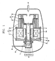
- Fig. 1 is a sectional view showing an example of the conventional reciprocating compressor
- Fig. 2 is an exploded perspective view showing an outer stator fixing apparatus of the conventional reciprocating compressor
- Fig. 3 is a front sectional view showing a fixed state of the outer stator in the conventional reciprocating compressor.
- the conventional reciprocating compressor includes: a frame unit 20 elastically supported in a casing 10; a reciprocating motor 30 supported by the frame unit 20, and having a mover 33 which linearly reciprocates; a compression unit 40 connected to the reciprocating motor 30 and supported by the frame unit 20; and a resonant spring unit 50 for elastically supporting the reciprocating motor 30 and inducing its resonant motion.
- the frame unit 20 includes: a front frame 21 for supporting a front side of the reciprocating motor 30, a middle frame 22 coupled to the front frame 21, for supporting a rear side of the reciprocating motor 30; and a rear frame 23 coupled to the middle frame 22, for supporting the resonant spring unit 50.
- the reciprocating motor 30 includes: an outer stator 31 having a coil winding and fixed to the front frame 21; an inner stator 32 positioned inside the outer stator 31 spaced therefrom by a certain air gap and fixedly inserted into a cylinder 41; a mover 33 interposed in the air gap between the outer stator 31 and the inner stator 32, for linearly reciprocating.
- the outer stator 31 includes a bobbin body 31 a in which the coil bonding is inserted; several core blocks 31 b are formed by laminating a plurality of stator core sheets in a circular arc shape, and inserted in both sides of the bobbin body 31 a to be coupled thereto; a molding body 31 c fixed to the bobbin body 31 a by molding a connected portion of each core block 31 b.
- the molding body 31 c is formed of an insulator such as epoxy so as to consecutively fix an outer circumferential surface of the bobbin body 31 a and the connected portion of each core block 31 b.
- the compression unit 40 includes: a cylinder 41 fixed to the front frame 21; a piston 42 slidably inserted in the cylinder 41 and coupled to the mover 33 of the reciprocating motor 30, for reciprocating in upper and lower directions; a suction valve 43 mounted on a front end surface of the piston 42, for opening/closing a suction path F; a discharge valve 44 mounted in an outlet of the cylinder 41, for restricting the discharge of a compressed gas; a valve spring 45 for elastically supporting the discharge valve 44; a discharge cover 46 having the discharge valve 44 and the valve spring 45 therein and covering the outlet of the cylinder 41.
- the resonant spring unit 50 includes: a spring support 51 coupled to a portion connected between the mover 33 and the piston 42; and a first resonant spring 52 and a second resonant spring 53 provided at upper and lower sides of the spring support 51 and formed of a compressed coil spring to elastically support the piston 42.
- M denotes a magnet
- P denotes a compression space
- SP denotes a suction pipe
- DP denotes a discharge pipe.
- the core block 31 b is formed by perforating a plurality of stator core sheets as a thin plate and laminating them. Afterwards, this core block 31 b is inserted in an outer side surface of the bobbin body 31 a having the coil winding in a particular mold, and then the molding body 31c is formed by performing an overmolding between a connected portion, between the outer circumferential surface of the bobbin body 31a and the core block 31b, and a space, between the outer circumferential surface of the bobbin body 31a and an inner circumferential surface of the core block 31 b, thereby resulting in forming the outer stator 31.
- the outer stator 31 is separated from the mold.
- the outer stator 31 positions between the front frame 21 and the middle frame 22 together with the inner stator 32 and then is fixedly coupled to the frame unit 20 by using a coupling bolt 24 and a coupling nut 25.
- a molding pressure generated when a molding material is injected during the process for fabricating the outer stator 31 of the reciprocating motor 30 or a contracting force generated when the molding material is hardened pressurize the core block 31 b, which may cause deformation of parts of the core block 31 b.
- a distance between cores positioned between the outer stator 31 and the inner stator 32 is narrower, and accordingly an appropriate air gap between the outer stator 31 and the inner stator 32 is not maintained, thereby causing degradation of efficiency and reliability of the compressor.
- an initial loss may occur when conditions of temperature and pressure for the molding material are established, and a defect rate may be increased due to the ununiformity of the product according to the injection molding temperature.
- the outer stator 31 is formed in a hemi-sealed shape, which may make it difficult to discharge heat and moisture from the coil winding and thus lower a motor efficiency.
- an object of the present invention is to provide a stator fixing apparatus of a reciprocating compressor and fabrication method thereof capable of preventing deformation of an initial shape or increase of a defect rate due to a molding material by omitting an overmolding process using the molding material in a fabrication method for a stator, and of improving efficiency and reliability of the reciprocating compressor by facilitating discharging of heat and moisture.
- a stator fixing apparatus of a reciprocating compressor comprising: a first frame on which a plurality of first core blocks formed by laminating a plurality of stator core sheets are radially coupled, the plurality of first core blocks being coupled to one side surface of a bobbin body; a second frame on which a plurality of second core blocks formed by laminating a plurality of stator core sheets are radially coupled, the plurality of second core blocks being coupled to the other side surface of the bobbin body; and a coupling portion formed at each contact portion between the first core block and the second core block, for coupling the first and second core blocks.
- a stator fixing apparatus of a reciprocating compressor comprises: a first frame on which a plurality of first core blocks formed by laminating a plurality of stator core sheets are radially coupled, the plurality of first core blocks being coupled to one side surface of a bobbin body; a second frame on which a plurality of second core blocks formed by laminating a plurality of stator core sheets are radially coupled, the plurality of second core blocks being coupled to the other side of the bobbin body; and a coupling member for coupling the first frame and the second frame so that the first and second core blocks are contact with each other to thusly be adhered closely to both sides of the bobbin body.
- a fabrication method for a stator fixing apparatus of a reciprocating compressor comprising the steps of: fabricating first core blocks and second core blocks by winding a coil on a bobbin body, perforating a plurality of stator core sheets in an appropriate shape, and thereafter laminating the perforated stator core sheets; radially positioning the first core blocks and the second core blocks on facing surfaces of a first frame and a second frame, respectively, whereby the arranged first and second core blocks respectively form a circular inner circumferential surface and an outer circumferential surface at which the first and second core blocks are arranged with a certain interval; fixedly-coupling each core block to each frame; and contacting the first core blocks and the second core blocks with each other to be adhered closely to both sides of the bobbin body.
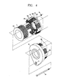
- Fig. 4 is a disassembled perspective view showing a fixing apparatus for an outer stator in a reciprocating compressor according to the present invention
- Fig. 5 is a front view showing a fixed state of the outer stator in the reciprocating compressor according to the present invention
- Fig. 6 is a lateral sectional view showing a fixed state of the outer stator in the reciprocating compressor according to the present invention.
- the stator fixing apparatus of the reciprocating compressor includes: a front frame 21 on which a plurality of first core blocks 130 formed by laminating a plurality of stator core sheets are radially coupled, the plurality of first core blocks 130 being coupled to one side surface of a bobbin body 110; a middle frame 22 on which a plurality of second core blocks 140 formed by laminating a plurality of stator core sheets are radially coupled, the plurality of second core blocks 140 being coupled to the other side surface of the bobbin body 110; and a coupling portion formed at each contact portion between the first core block 130 and the second core block 140, for coupling the first and second core blocks 130 and 140.
- the bobbin body 110 with a cylindrical shape has a space of which one side is open, and a coil C is wound on an outer circumferential surface of the bobbin body 110.
- the bobbin body 110 is formed by a molding using resin such as plastic so as to act as an insulator.
- Each core block 130 and 140 includes a horizontal portion (not shown and 141) horizontally coupled to an inner side surface of each frame 21 and 22, and a vertical portion (not shown and 142) integrally formed with the horizontal portion (not shown and 141) and vertically extending inwardly to the inside of each frame 21 and 22.
- a welded portion 125 for fixedly coupling the middle frame 22 and the second core blocks 140 is provided at an interface between the second core blocks 140 and the middle frame 22.
- Each welded portion 125 is preferably formed and fixed near the middle part of the horizontal portion 141 of the second core block 140 by welding.
- the welded portion 125 may also be formed on an outer side surface where the horizontal portion 141 meets the vertical portion 142 to be contact with the middle frame 22, namely, a position where an outer circumferential surface of the second core block 140 is contact with the middle frame 22. Otherwise, the welded portion 125 may not be formed anywhere, but rather the middle frame 22 and the second core blocks 140 may be bonded on the contact surface between the horizontal portion 141 and the middle frame 22 by using an adhesive.
- the front frame 21 and the first core blocks 130 may also be coupled to each other according to the same ways as aforementioned.
- the coupling portion 150 for coupling the first core block 130 and the second core block 140 is preferably formed at the most outer side surface of the contact portion 135 between the first core block 130 and the second core block 140 in a radius direction.
- the coupling portion 150 can be formed by welding, and also be formed by being bonded with the adhesive.
- a coupling force therebetween may be weak, so that the two core blocks 130 and 140 may preferably be coupled to each other more firmly by tightening each frame 21 and 22 using the bolt 24 and the nut 25.
- the coupling portion 150 may not be formed between two core blocks by such welding, but each frame 21 and 22 may be coupled only using the coupling member such as the bolt and nut. That is, the coupling member adheres the first core block 130 and the second core block 140 closely to both sides of the bobbin body 110 by contacting the first and second core blocks 130 and 140 with each other.
- the coupling member is not limited on the bolt and nut, but may include the adhesive or other rivets or any other type of connecting device or any combination thereof.
- stator fixing apparatus of the reciprocating compressor A fabrication method for the stator fixing apparatus of the reciprocating compressor according to the present invention will now be explained.
- the coil C is wound on the bobbin body 110.
- a plurality of stator core sheets are perforated or stamped out in an appropriate shape and laminated so as to fabricate the first core block 130 and the second core block 140.
- first core block 130 and the second core block 140 are radially positioned on facing surfaces of each of the front frame 21 and the middle frame 22.
- first and second core blocks 130 and 140 form a circular inner circumferential surface and an outer circumferential surface at which first and second core blocks 130 and 140 are arranged with a certain interval.
- the welded portion 125 is formed at a part of an interface between each core block 130 and 140 and each frame 21 and 22, so as to couple each core block 130 and 140 and each frame 21 and 22 by welding.
- each frame 21 and 22 are first fixed by the coupling member, the coupling portion 150 of each core block 130 and 140 may be welded.
- each frame 21 and 22 is fixed only using the coupling member and each core block 130 and 140 may not individually be coupled to each other by such welding.
- the assembling process for the stator can simplified, by welding the core blocks for coupling thereto, which leads to reduction of fabrication cost and improvement of productivity.
- the open side of the bobbin body is not sealed by the molding material.
- heat generated from the coil can easily be discharged, and the inside of the bobbin body can be protected from moisture, thereby improving efficiency and reliability of the reciprocating compressor.
Landscapes
- Engineering & Computer Science (AREA)
- Power Engineering (AREA)
- Civil Engineering (AREA)
- Structural Engineering (AREA)
- Mechanical Engineering (AREA)
- General Engineering & Computer Science (AREA)
- Compressor (AREA)
- Reciprocating, Oscillating Or Vibrating Motors (AREA)
Abstract
Description
- The present disclosure relates to subject matter contained in priority Korean Application No. 03405/2005, filed on January 13, 2005, the disclosure of which is herein expressly incorporated by reference in its entirety.
- The present invention relates to a reciprocating compressor, and particularly, to a stator fixing apparatus of a reciprocating compressor and a fabrication method thereof capable of preventing deformation of an original shape or increase of a defect rate due to a molding material by omitting an over-molding process using the molding material in a stator fabricating process, and of improving efficiency and reliability of the reciprocating compressor by facilitating discharging of heat and moisture.
- In general, compressors convert electrical energy into kinetic energy and compress a refrigerant gas by the kinetic energy. The compressors, as a main component making up a refrigeration cycle system, include various types such as a rotary compressor, a scroll compressor, a reciprocating compressor and the like according to a compression mechanism. The refrigeration cycle system including such compressors are used in refrigerators, air-conditioners, showcase coolers and the like.
- The reciprocating compressor among those compressors is a compressor in which a piston linearly reciprocates in a cylinder, and sucks and compresses gas for discharging it, an example of which will be shown as follows.
- Fig. 1 is a sectional view showing an example of the conventional reciprocating compressor, Fig. 2 is an exploded perspective view showing an outer stator fixing apparatus of the conventional reciprocating compressor, and Fig. 3 is a front sectional view showing a fixed state of the outer stator in the conventional reciprocating compressor.
- As shown in those drawings, the conventional reciprocating compressor includes: a
frame unit 20 elastically supported in acasing 10; areciprocating motor 30 supported by theframe unit 20, and having amover 33 which linearly reciprocates; acompression unit 40 connected to thereciprocating motor 30 and supported by theframe unit 20; and aresonant spring unit 50 for elastically supporting the reciprocatingmotor 30 and inducing its resonant motion. - The
frame unit 20 includes: afront frame 21 for supporting a front side of the reciprocatingmotor 30, amiddle frame 22 coupled to thefront frame 21, for supporting a rear side of the reciprocatingmotor 30; and arear frame 23 coupled to themiddle frame 22, for supporting theresonant spring unit 50. Thereciprocating motor 30 includes: anouter stator 31 having a coil winding and fixed to thefront frame 21; aninner stator 32 positioned inside theouter stator 31 spaced therefrom by a certain air gap and fixedly inserted into acylinder 41; amover 33 interposed in the air gap between theouter stator 31 and theinner stator 32, for linearly reciprocating. - The
outer stator 31 includes abobbin body 31 a in which the coil bonding is inserted;several core blocks 31 b are formed by laminating a plurality of stator core sheets in a circular arc shape, and inserted in both sides of thebobbin body 31 a to be coupled thereto; amolding body 31 c fixed to thebobbin body 31 a by molding a connected portion of eachcore block 31 b. - The
molding body 31 c is formed of an insulator such as epoxy so as to consecutively fix an outer circumferential surface of thebobbin body 31 a and the connected portion of eachcore block 31 b. - The
compression unit 40 includes: acylinder 41 fixed to thefront frame 21; apiston 42 slidably inserted in thecylinder 41 and coupled to themover 33 of the reciprocatingmotor 30, for reciprocating in upper and lower directions; asuction valve 43 mounted on a front end surface of thepiston 42, for opening/closing a suction path F; adischarge valve 44 mounted in an outlet of thecylinder 41, for restricting the discharge of a compressed gas; avalve spring 45 for elastically supporting thedischarge valve 44; adischarge cover 46 having thedischarge valve 44 and thevalve spring 45 therein and covering the outlet of thecylinder 41. - The
resonant spring unit 50 includes: aspring support 51 coupled to a portion connected between themover 33 and thepiston 42; and a firstresonant spring 52 and a secondresonant spring 53 provided at upper and lower sides of thespring support 51 and formed of a compressed coil spring to elastically support thepiston 42. - Among previously unexplained reference symbols, M denotes a magnet, P denotes a compression space, SP denotes a suction pipe, and DP denotes a discharge pipe.
- An operation of such conventional reciprocating compressor and a structure thereof will now be explained.
- When power is applied to the
outer stator 31 of thereciprocating motor 30, a flux is formed between theouter stator 31 and theinner stator 32, and thus themover 33 and thepiston 42 move along the direction of the flux. A this time, themover 33 linearly reciprocates by theresonant spring unit 50 and thepiston 42 also linearly reciprocates in thecylinder 41, whereby a pressure difference occurs in the compression space P of thecylinder 41. As a result, a series of processes, namely, sucking a refrigerant gas, compressing the refrigerant gas until it has a certain pressure, and discharging it, are repeatedly performed. - Here, in order to assemble the reciprocating compressor, as shown in Fig. 2, the
core block 31 b is formed by perforating a plurality of stator core sheets as a thin plate and laminating them. Afterwards, thiscore block 31 b is inserted in an outer side surface of thebobbin body 31 a having the coil winding in a particular mold, and then themolding body 31c is formed by performing an overmolding between a connected portion, between the outer circumferential surface of thebobbin body 31a and thecore block 31b, and a space, between the outer circumferential surface of thebobbin body 31a and an inner circumferential surface of thecore block 31 b, thereby resulting in forming theouter stator 31. Thereafter, theouter stator 31 is separated from the mold. Theouter stator 31 positions between thefront frame 21 and themiddle frame 22 together with theinner stator 32 and then is fixedly coupled to theframe unit 20 by using acoupling bolt 24 and acoupling nut 25. - However, in the conventional reciprocating compressor, a molding pressure generated when a molding material is injected during the process for fabricating the
outer stator 31 of the reciprocatingmotor 30 or a contracting force generated when the molding material is hardened pressurize thecore block 31 b, which may cause deformation of parts of thecore block 31 b. As a result, a distance between cores positioned between theouter stator 31 and theinner stator 32 is narrower, and accordingly an appropriate air gap between theouter stator 31 and theinner stator 32 is not maintained, thereby causing degradation of efficiency and reliability of the compressor. - Moreover, at the time of an initial injection of the
outer stator 31, an initial loss may occur when conditions of temperature and pressure for the molding material are established, and a defect rate may be increased due to the ununiformity of the product according to the injection molding temperature. In addition, in case of the overmolding structure at the time of assembling theouter stator 31 by injection, as shown in Fig. 3, theouter stator 31 is formed in a hemi-sealed shape, which may make it difficult to discharge heat and moisture from the coil winding and thus lower a motor efficiency. - Therefore, an object of the present invention is to provide a stator fixing apparatus of a reciprocating compressor and fabrication method thereof capable of preventing deformation of an initial shape or increase of a defect rate due to a molding material by omitting an overmolding process using the molding material in a fabrication method for a stator, and of improving efficiency and reliability of the reciprocating compressor by facilitating discharging of heat and moisture.
- To achieve these and other advantages and in accordance with the purpose of the present invention, as embodied and broadly described herein, there is provided a stator fixing apparatus of a reciprocating compressor comprising: a first frame on which a plurality of first core blocks formed by laminating a plurality of stator core sheets are radially coupled, the plurality of first core blocks being coupled to one side surface of a bobbin body; a second frame on which a plurality of second core blocks formed by laminating a plurality of stator core sheets are radially coupled, the plurality of second core blocks being coupled to the other side surface of the bobbin body; and a coupling portion formed at each contact portion between the first core block and the second core block, for coupling the first and second core blocks.
- According to another embodiment of the present invention, a stator fixing apparatus of a reciprocating compressor comprises: a first frame on which a plurality of first core blocks formed by laminating a plurality of stator core sheets are radially coupled, the plurality of first core blocks being coupled to one side surface of a bobbin body; a second frame on which a plurality of second core blocks formed by laminating a plurality of stator core sheets are radially coupled, the plurality of second core blocks being coupled to the other side of the bobbin body; and a coupling member for coupling the first frame and the second frame so that the first and second core blocks are contact with each other to thusly be adhered closely to both sides of the bobbin body.
- To achieve these and other advantages and in accordance with the purpose of the present invention, as embodied and broadly described herein, there is provided a fabrication method for a stator fixing apparatus of a reciprocating compressor comprising the steps of: fabricating first core blocks and second core blocks by winding a coil on a bobbin body, perforating a plurality of stator core sheets in an appropriate shape, and thereafter laminating the perforated stator core sheets; radially positioning the first core blocks and the second core blocks on facing surfaces of a first frame and a second frame, respectively, whereby the arranged first and second core blocks respectively form a circular inner circumferential surface and an outer circumferential surface at which the first and second core blocks are arranged with a certain interval; fixedly-coupling each core block to each frame; and contacting the first core blocks and the second core blocks with each other to be adhered closely to both sides of the bobbin body.
- The foregoing and other objects, features, aspects and advantages of the present invention will become more apparent from the following detailed description of the present invention when taken in conjunction with the accompanying drawings.
- The present invention is further described in the detailed description which follows, by reference to the noted plurality of drawings by way of non-limiting examples of preferred embodiments of the present invention, in which like reference numerals represent similar parts throughout the several views of the drawings, and wherein:
- Fig. 1 is a sectional view showing an embodiment of the conventional reciprocating compressor;
- Fig. 2 is a disassembled perspective view showing an outer stator fixing apparatus in the conventional reciprocating compressor;
- Fig. 3 is a front view showing a fixed state of the outer stator in the conventional reciprocating compressor;
- Fig. 4 is a disassembled perspective view showing an outer stator fixing apparatus in a reciprocating compressor according to the present invention;
- Fig. 5 is a front view showing a fixed state of the outer stator in the reciprocating compressor according to the present invention; and
- Fig. 6 is a lateral sectional view showing a fixed state of the outer stator in the reciprocating compressor according to the present invention.
- The above and other objects, features and advantages of the present invention will be made apparent from the following description of the preferred embodiments, given as non-limiting examples, with reference to the accompanying drawings.
- Fig. 4 is a disassembled perspective view showing a fixing apparatus for an outer stator in a reciprocating compressor according to the present invention, Fig. 5 is a front view showing a fixed state of the outer stator in the reciprocating compressor according to the present invention, and Fig. 6 is a lateral sectional view showing a fixed state of the outer stator in the reciprocating compressor according to the present invention.
- As shown in those drawings, the stator fixing apparatus of the reciprocating compressor includes: a
front frame 21 on which a plurality offirst core blocks 130 formed by laminating a plurality of stator core sheets are radially coupled, the plurality offirst core blocks 130 being coupled to one side surface of abobbin body 110; amiddle frame 22 on which a plurality ofsecond core blocks 140 formed by laminating a plurality of stator core sheets are radially coupled, the plurality ofsecond core blocks 140 being coupled to the other side surface of thebobbin body 110; and a coupling portion formed at each contact portion between thefirst core block 130 and thesecond core block 140, for coupling the first andsecond core blocks - The
bobbin body 110 with a cylindrical shape has a space of which one side is open, and a coil C is wound on an outer circumferential surface of thebobbin body 110. Thebobbin body 110 is formed by a molding using resin such as plastic so as to act as an insulator. - Each
core block frame frame - Preferably, a
welded portion 125 for fixedly coupling themiddle frame 22 and thesecond core blocks 140 is provided at an interface between thesecond core blocks 140 and themiddle frame 22. Eachwelded portion 125 is preferably formed and fixed near the middle part of thehorizontal portion 141 of thesecond core block 140 by welding. Thewelded portion 125 may also be formed on an outer side surface where thehorizontal portion 141 meets thevertical portion 142 to be contact with themiddle frame 22, namely, a position where an outer circumferential surface of thesecond core block 140 is contact with themiddle frame 22. Otherwise, thewelded portion 125 may not be formed anywhere, but rather themiddle frame 22 and thesecond core blocks 140 may be bonded on the contact surface between thehorizontal portion 141 and themiddle frame 22 by using an adhesive. Thefront frame 21 and thefirst core blocks 130 may also be coupled to each other according to the same ways as aforementioned. - The
coupling portion 150 for coupling thefirst core block 130 and thesecond core block 140 is preferably formed at the most outer side surface of thecontact portion 135 between thefirst core block 130 and thesecond core block 140 in a radius direction. - The
coupling portion 150 can be formed by welding, and also be formed by being bonded with the adhesive. - Here, when the two
core blocks core blocks frame bolt 24 and thenut 25. - On the other hand, the
coupling portion 150 may not be formed between two core blocks by such welding, but eachframe first core block 130 and thesecond core block 140 closely to both sides of thebobbin body 110 by contacting the first andsecond core blocks - The coupling member is not limited on the bolt and nut, but may include the adhesive or other rivets or any other type of connecting device or any combination thereof.
- A fabrication method for the stator fixing apparatus of the reciprocating compressor according to the present invention will now be explained. First, the coil C is wound on the
bobbin body 110. A plurality of stator core sheets are perforated or stamped out in an appropriate shape and laminated so as to fabricate thefirst core block 130 and thesecond core block 140. - Next, the
first core block 130 and thesecond core block 140 are radially positioned on facing surfaces of each of thefront frame 21 and themiddle frame 22. Thus, the first and second core blocks 130 and 140 form a circular inner circumferential surface and an outer circumferential surface at which first and second core blocks 130 and 140 are arranged with a certain interval. Next, the weldedportion 125 is formed at a part of an interface between eachcore block frame core block frame - Next, when the
first core block 130 and thesecond core block 140 are coupled to both side surfaces of thebobbin body 110 so as to be in contact with each other, one side of the contact portion between the twocore blocks coupling portion 150. At this time, preferably, the twocore blocks front frame 21 and themiddle frame 22 using thebolt 24 and thenut 25. Conversely, after eachframe coupling portion 150 of eachcore block frame core block - Hereinafter, an effect of the present invention will now be described. By omitting the process for performing the overmolding by injecting the molding material in the process for fabricating the stator, the deformation of the stator caused by the injection pressure of the molding material generated at the time of injecting the molding material can be prevented. In addition, by decreasing the deformation of the stator caused by the injection pressure, the gap between the outer and inner stators is uniformly maintained, which can improve stability and reliability of the reciprocating compressor.
- Furthermore, the assembling process for the stator can simplified, by welding the core blocks for coupling thereto, which leads to reduction of fabrication cost and improvement of productivity.
- In addition, the open side of the bobbin body is not sealed by the molding material. As a result, heat generated from the coil can easily be discharged, and the inside of the bobbin body can be protected from moisture, thereby improving efficiency and reliability of the reciprocating compressor.
- Although the invention has been described with reference to an exemplary embodiment, it is understood that the words that have been used are words of description and illustration, rather than words of limitation. Changes may be made, within the purview of the appended claims, as presently stated and as amended, without departing from the scope and spirit of the present invention in its aspects. Although the invention has been described herein with reference to particular means, materials and embodiments, the invention is not intended to be limited to the particulars disclosed herein. Instead, the invention extends to all functionally equivalent structures, methods and uses, such as are within the scope of the appended claims.
- The particulars shown herein are by way of example and for purposes of illustrative discussion of the embodiments of the present invention only and are presented in the cause of providing what is believed to be the most useful and readily understood description of the principles and conceptual aspects of the present invention. In this regard, no attempt is made to show structural details of the present invention I more detail than is necessary for the fundamental understanding of the present invention, the description is taken with the drawings making apparent to those skilled in the art how the forms of the present invention may be embodied in practice.
Claims (26)
- A stator fixing apparatus of a reciprocating compressor comprising:a first frame on which a plurality of first core blocks, each comprising a plurality of laminated stator core sheets, are radially coupled, the plurality of first core blocks being configured to be coupled to one side surface of a bobbin body;a second frame on which a plurality of second core blocks, each comprising a plurality of laminated stator core sheets, are radially coupled, the plurality of second core blocks being configured to be coupled to the other side surface of the bobbin body; anda coupling portion provided at each contact portion between the first core block and the second core block, for coupling the first and second core blocks.
- The apparatus of claim 1, wherein each core block comprises:a first portion coupled to an inner side surface of each frame and that extend away from the frame; anda second portion integral with the first portion and extending along a surface of each frame.
- The apparatus of claim 1, wherein each frame and each core block are coupled by a weld at an interface therebetween.
- The apparatus of claim 1, wherein each frame and each core block are coupled by an adhesive on a contact surface therebetween.
- The apparatus of claim 1, wherein the coupling portion comprises a weld between outer side surfaces of the contact portion between the first core block and the second core block.
- The apparatus of claim 1, further comprising a coupling member for fixing each frame so that the first core block and the second core block contact each other and contact both sides of the bobbin body.
- The apparatus of claim 6, wherein the coupling member is one of a bolt, a nut, an adhesive and a rivet.
- A stator fixing apparatus of a reciprocating compressor comprising:a first frame on which a plurality of first core blocks, each comprising a plurality of laminated stator core sheets, are radially coupled, the plurality of first core blocks being configured to be coupled to one side surface of a bobbin body;a second frame on which a plurality of second core blocks, each comprising a plurality of laminated stator core sheets, are radially coupled, the plurality of second core blocks being configured to be coupled to the other side of the bobbin body; anda coupling member for coupling the first frame and the second frame so that the first and second core blocks contact each other and contact both sides of the bobbin body.
- The apparatus of claim 8, wherein each core block comprises:a first portion coupled to an inner side surface of each frame and that extend away from the frame; anda second portion integral with the first portion and extending along a surface of each frame.
- The apparatus of claim 8, wherein each frame and each core block are coupled by a weld at an interface therebetween.
- The apparatus of claim 8, wherein each frame and each core block are coupled by an adhesive on a contact surface therebetween.
- The apparatus of claim 8, further comprising a coupling portion for coupling the first core block and the second core block at a contact between the first core block and the second core block.
- The apparatus of claim 12, wherein the coupling portion comprises a weld at outer side surfaces of the contact between the first core block and the second core block
- A method for fabricating a stator fixing apparatus of a reciprocating compressor, the method comprising:fabricating first core blocks and second core blocks by winding a coil on a bobbin body, cutting a plurality of stator core sheets in an appropriate shape, andlaminating the plurality of stator core sheets;radially positioning the first core blocks and the second core blocks on facing surfaces of a first frame and a second frame, respectively, wherein the first andsecond core blocks are positioned to form a circular inner circumferential surface and an outer circumferential surface at which the first and second core blocks are spaced by a certain interval;fixedly-coupling each core block to each frame; andcontacting the first core blocks and the second core blocks with each other to contact both sides of the bobbin body.
- The method of claim 14, wherein the fixedly coupling comprises forming a weld at an interface between each core block and each frame so as to fix each core block and each frame.
- The method of claim 14, wherein contacting comprises coupling the first and second core blocks by welding a side of the contact portion between the two core blocks when the first and second core blocks contact both side surfaces of the bobbin body and contact each other.
- The method of claim 14, wherein contacting comprises coupling the first frame and the second frame to each other by using a coupling member.
- The method of claim 14, wherein contacting comprises coupling the first frame and the second frame to each other using a coupling member, and thereafter welding the first and second core blocks to each other at a side of the contact portion between the two core blocks such that the first and second core blocks are coupled to both side surfaces of the bobbin body and thus contact each other.
- The method of claim 14, wherein contacting the first and second core blocks are welded to each other at a side of the contact portion between the two core blocks such that the first and second core blocks are coupled to both side surfaces of the bobbin body and thus contact each other, and thereafter the first frame and the second frame are coupled to each other using a coupling member.
- A stator comprising:a first frame, a plurality of first core blocks attached about a periphery of the first frame and extending outwardly from the first frame;a second frame, a plurality of second core blocks attached about a periphery of the second frame and extending outwardly from the second frame;each of the core blocks comprising a plurality of core sheets secured together;wherein each of the first core blocks is attached, at a free end, to a corresponding one of the second core blocks at a free end of the second core block, the first and second frames, with the first and second core blocks extending therefrom and attached to each other, being configured to be coupled about a bobbin body and to be secured to the bobbin body.
- The stator according to claim 20, each of said first and second core blocks having a first portion extending along a surface of one of the first and second frames and extending inwardly from a periphery of one of the first and second frames, and a second portion, at the periphery of one of the first and second frames that extends outwardly from the frames and terminates in the free end of the core blocks.
- The stator according to claim 20, wherein the attachment between the free ends of the first and second core blocks comprises a weld.
- The stator according to claim 20, wherein attachment of the core blocks to the frames comprises a weld.
- The stator according to claim 20, wherein each of the first and second core blocks comprises a plurality of laminated core sheets.
- The stator according to claim 20, wherein each of the first and second frames are configured to be fixed to each other by one of an adhesive, rivets or nuts and bolts.
- A method for fabricating a stator, comprising:securing first core blocks about a periphery of a first frame;securing second core blocks about a periphery of a second frame;positioning the first and second frames, with core blocks attached, about a bobbin, such that free ends of the first and second core blocks are in contact; andfixing the first and second core blocks to each other at the contacting free ends of the core blocks.
Applications Claiming Priority (1)
| Application Number | Priority Date | Filing Date | Title |
|---|---|---|---|
| KR1020050003405A KR100565264B1 (en) | 2005-01-13 | 2005-01-13 | External stator fixing device for reciprocating compressor |
Publications (2)
| Publication Number | Publication Date |
|---|---|
| EP1681756A1 true EP1681756A1 (en) | 2006-07-19 |
| EP1681756B1 EP1681756B1 (en) | 2013-11-06 |
Family
ID=36096270
Family Applications (1)
| Application Number | Title | Priority Date | Filing Date |
|---|---|---|---|
| EP05021257.0A Ceased EP1681756B1 (en) | 2005-01-13 | 2005-09-29 | Stator of a reciprocating compressor |
Country Status (5)
| Country | Link |
|---|---|
| US (1) | US7659642B2 (en) |
| EP (1) | EP1681756B1 (en) |
| JP (1) | JP2006194236A (en) |
| KR (1) | KR100565264B1 (en) |
| CN (1) | CN100563081C (en) |
Cited By (1)
| Publication number | Priority date | Publication date | Assignee | Title |
|---|---|---|---|---|
| EP3521617A1 (en) * | 2018-02-01 | 2019-08-07 | Lg Electronics Inc. | Linear compressor |
Families Citing this family (4)
| Publication number | Priority date | Publication date | Assignee | Title |
|---|---|---|---|---|
| US8810103B2 (en) * | 2007-08-14 | 2014-08-19 | Gang Liu | Conductive wire unit and generator with closed magnetic path |
| WO2015033488A1 (en) * | 2013-09-05 | 2015-03-12 | パナソニックIpマネジメント株式会社 | Compressor |
| US9841011B2 (en) * | 2014-07-21 | 2017-12-12 | Lg Electronics Inc. | Linear compressor and a linear motor for a linear compressor |
| KR102240028B1 (en) * | 2014-07-21 | 2021-04-14 | 엘지전자 주식회사 | Linear compressor and linear motor |
Citations (8)
| Publication number | Priority date | Publication date | Assignee | Title |
|---|---|---|---|---|
| JPS5475005A (en) * | 1977-11-28 | 1979-06-15 | Hitachi Ltd | Method for fixing rotor core of flat motor |
| GB2037093A (en) * | 1978-11-06 | 1980-07-02 | Jones & Co Ltd W | Stator assemblies for electrical rotating machines |
| JPS62281743A (en) * | 1986-05-29 | 1987-12-07 | Matsushita Electric Ind Co Ltd | How to assemble a stepping motor |
| US5318412A (en) * | 1992-04-03 | 1994-06-07 | General Electric Company | Flexible suspension for an oil free linear motor compressor |
| US20020105247A1 (en) * | 2001-02-02 | 2002-08-08 | Park Kyeong Bae | Stator structure of reciprocating motor |
| US20030147759A1 (en) * | 2002-02-01 | 2003-08-07 | Samsung Electronics Co., Ltd | Linear compressor |
| WO2004006413A1 (en) * | 2002-07-03 | 2004-01-15 | Empresa Brasileira De Compressores S/A Embraco | Process for forming the stator of a linear motor, annular stack of lamination elements and stator for an electric motor |
| US20040025325A1 (en) * | 2000-09-26 | 2004-02-12 | Shinichiro Kawano | Linear actuator |
Family Cites Families (28)
| Publication number | Priority date | Publication date | Assignee | Title |
|---|---|---|---|---|
| US3119940A (en) * | 1961-05-16 | 1964-01-28 | Sperry Rand Corp | Magnetomotive actuators of the rectilinear output type |
| FR2544926B1 (en) * | 1983-04-20 | 1986-05-30 | Jarret Jacques | MAGNETIC RING FOR RECTILINEAR FREE PISTON GENERATORS |
| JP2642361B2 (en) | 1987-09-11 | 1997-08-20 | 株式会社東芝 | Method of manufacturing elevator hoist |
| US5261799A (en) * | 1992-04-03 | 1993-11-16 | General Electric Company | Balanced linear motor compressor |
| US5257915A (en) * | 1992-04-03 | 1993-11-02 | General Electric Company | Oil free linear motor compressor |
| US6942469B2 (en) * | 1997-06-26 | 2005-09-13 | Crystal Investments, Inc. | Solenoid cassette pump with servo controlled volume detection |
| JP3560450B2 (en) * | 1997-10-29 | 2004-09-02 | アルプス電気株式会社 | Game console operating device |
| US6077054A (en) * | 1997-12-23 | 2000-06-20 | Samsung Electronics Co., Ltd. | Stator of linear compressor |
| KR100349709B1 (en) * | 1997-12-23 | 2002-11-23 | 삼성전자 주식회사 | Stator of Linear Compressor |
| KR100504848B1 (en) * | 1998-12-17 | 2005-10-14 | 엘지전자 주식회사 | Motor mounting structure |
| US6242823B1 (en) * | 1999-02-05 | 2001-06-05 | Wayne Griswold | Linear electric machine |
| JP2000333436A (en) * | 1999-05-18 | 2000-11-30 | Matsushita Electric Ind Co Ltd | Magnetic circuit of linear motor drive |
| ATE397802T1 (en) * | 1999-06-21 | 2008-06-15 | Fisher & Paykel Appliances Ltd | LINEAR MOTOR |
| JP2002119035A (en) * | 2000-10-03 | 2002-04-19 | Nippon Pachinko Buhin Kk | Actuator and gaming machine part using the same |
| BR0102566A (en) * | 2001-05-14 | 2003-02-25 | Brasil Compressores Sa | Linear motor and linear compressor including said motor |
| NZ515578A (en) * | 2001-11-20 | 2004-03-26 | Fisher & Paykel Appliances Ltd | Reduction of power to free piston linear motor to reduce piston overshoot |
| KR100442389B1 (en) * | 2001-11-23 | 2004-07-30 | 엘지전자 주식회사 | Reciprocating compressor |
| JP2004064838A (en) * | 2002-07-26 | 2004-02-26 | Sankyo Seiki Mfg Co Ltd | Linear actuator, pump device and compressor device using the same |
| KR100533043B1 (en) * | 2002-11-01 | 2005-12-05 | 엘지전자 주식회사 | Winding coil structure for reciprocating and manufacture method thereof |
| JP3866209B2 (en) * | 2003-03-18 | 2007-01-10 | 日本電産サンキョー株式会社 | Linear actuator, pump device and compressor device using the same |
| KR100548270B1 (en) * | 2003-04-18 | 2006-02-02 | 엘지전자 주식회사 | Stator Fastening Structure of Reciprocating Compressor |
| KR100529902B1 (en) | 2003-06-04 | 2005-11-22 | 엘지전자 주식회사 | Outer stator mounting structure of linear compressor |
| KR100529901B1 (en) * | 2003-06-04 | 2005-11-22 | 엘지전자 주식회사 | The linear motor of a linear compressor |
| KR100707418B1 (en) * | 2003-06-05 | 2007-04-13 | 엘지전자 주식회사 | Control method of linear compressor |
| JP3579416B1 (en) * | 2003-06-16 | 2004-10-20 | シャープ株式会社 | Linear motor device and manufacturing method thereof, linear compressor and Stirling engine |
| CN2632922Y (en) | 2003-06-26 | 2004-08-11 | 中纺机电研究所 | Switch magnetic resistance motor for lowering noise |
| KR100556800B1 (en) * | 2004-03-25 | 2006-03-10 | 엘지전자 주식회사 | Inner stator fixing device of reciprocating compressor |
| KR100556974B1 (en) * | 2004-04-29 | 2006-03-03 | 엘지전자 주식회사 | Outer core assembly structure of stator for linear motor and its method |
-
2005
- 2005-01-13 KR KR1020050003405A patent/KR100565264B1/en not_active Expired - Fee Related
- 2005-08-01 JP JP2005223054A patent/JP2006194236A/en active Pending
- 2005-09-29 EP EP05021257.0A patent/EP1681756B1/en not_active Ceased
- 2005-09-30 US US11/239,127 patent/US7659642B2/en not_active Expired - Fee Related
- 2005-10-25 CN CNB2005101180110A patent/CN100563081C/en not_active Expired - Fee Related
Patent Citations (8)
| Publication number | Priority date | Publication date | Assignee | Title |
|---|---|---|---|---|
| JPS5475005A (en) * | 1977-11-28 | 1979-06-15 | Hitachi Ltd | Method for fixing rotor core of flat motor |
| GB2037093A (en) * | 1978-11-06 | 1980-07-02 | Jones & Co Ltd W | Stator assemblies for electrical rotating machines |
| JPS62281743A (en) * | 1986-05-29 | 1987-12-07 | Matsushita Electric Ind Co Ltd | How to assemble a stepping motor |
| US5318412A (en) * | 1992-04-03 | 1994-06-07 | General Electric Company | Flexible suspension for an oil free linear motor compressor |
| US20040025325A1 (en) * | 2000-09-26 | 2004-02-12 | Shinichiro Kawano | Linear actuator |
| US20020105247A1 (en) * | 2001-02-02 | 2002-08-08 | Park Kyeong Bae | Stator structure of reciprocating motor |
| US20030147759A1 (en) * | 2002-02-01 | 2003-08-07 | Samsung Electronics Co., Ltd | Linear compressor |
| WO2004006413A1 (en) * | 2002-07-03 | 2004-01-15 | Empresa Brasileira De Compressores S/A Embraco | Process for forming the stator of a linear motor, annular stack of lamination elements and stator for an electric motor |
Non-Patent Citations (3)
| Title |
|---|
| PATENT ABSTRACTS OF JAPAN vol. 003, no. 096 (E - 130) 15 August 1979 (1979-08-15) * |
| PATENT ABSTRACTS OF JAPAN vol. 012, no. 174 (E - 612) 24 May 1988 (1988-05-24) * |
| PATENT ABSTRACTS OF JAPAN vol. 013, no. 295 (E - 783) 7 July 1989 (1989-07-07) * |
Cited By (3)
| Publication number | Priority date | Publication date | Assignee | Title |
|---|---|---|---|---|
| EP3521617A1 (en) * | 2018-02-01 | 2019-08-07 | Lg Electronics Inc. | Linear compressor |
| EP3848583A1 (en) * | 2018-02-01 | 2021-07-14 | LG Electronics Inc. | Linear compressor |
| US11225958B2 (en) | 2018-02-01 | 2022-01-18 | Lg Electronics Inc. | Linear compressor |
Also Published As
| Publication number | Publication date |
|---|---|
| KR100565264B1 (en) | 2006-03-30 |
| CN1805243A (en) | 2006-07-19 |
| CN100563081C (en) | 2009-11-25 |
| EP1681756B1 (en) | 2013-11-06 |
| US7659642B2 (en) | 2010-02-09 |
| JP2006194236A (en) | 2006-07-27 |
| US20060152102A1 (en) | 2006-07-13 |
Similar Documents
| Publication | Publication Date | Title |
|---|---|---|
| JP4727950B2 (en) | Outer stator of motor for linear compressor | |
| EP1580427B1 (en) | Structure for fixing motor stator of reciprocating compressor | |
| US20100310393A1 (en) | Stator for linear compressor | |
| US7617594B2 (en) | Apparatus for fixing a stator of a motor of a reciprocal compressor | |
| KR100442389B1 (en) | Reciprocating compressor | |
| US20090079292A1 (en) | Interphase insulating sheet of rotating electric machine, method for manufacturing interphase insulating sheet, and electric compressor | |
| US7385319B2 (en) | Motor fixing structure of reciprocating compressor | |
| US20130115116A1 (en) | Reciprocating compressor | |
| JP4109249B2 (en) | Stator fixing device for reciprocating compressor | |
| US8678788B2 (en) | Linear compressor | |
| WO2005040611A1 (en) | Reciprocating compressor | |
| EP1681756A1 (en) | Stator of a reciprocating compressor and fabrication method | |
| KR100480376B1 (en) | Structure for fixing magnet in reciprocating compressor | |
| KR20090100690A (en) | Stator of linear compressor | |
| US7061145B2 (en) | Apparatus for fixing stator of reciprocating compressor | |
| KR100273430B1 (en) | Magnet fixed structure of linear compressor | |
| KR100648788B1 (en) | Permanent magnet fixing structure of linear compressor | |
| KR100608695B1 (en) | Inner stator fixing structure of reciprocating compressor | |
| JP2005307959A (en) | Linear compressor | |
| KR101065794B1 (en) | Method of manufacturing the mover of the linear motor | |
| KR101204547B1 (en) | Linear motor for linear compressor | |
| KR100543327B1 (en) | Linear compressor | |
| KR20180091451A (en) | Linear compressor | |
| KR20070068183A (en) | Reciprocating compressor | |
| KR20050060931A (en) | Device for fixing inner stator of reciprocating compressor |
Legal Events
| Date | Code | Title | Description |
|---|---|---|---|
| PUAI | Public reference made under article 153(3) epc to a published international application that has entered the european phase |
Free format text: ORIGINAL CODE: 0009012 |
|
| AK | Designated contracting states |
Kind code of ref document: A1 Designated state(s): AT BE BG CH CY CZ DE DK EE ES FI FR GB GR HU IE IS IT LI LT LU LV MC NL PL PT RO SE SI SK TR |
|
| AX | Request for extension of the european patent |
Extension state: AL BA HR MK YU |
|
| 17P | Request for examination filed |
Effective date: 20060915 |
|
| 17Q | First examination report despatched |
Effective date: 20061030 |
|
| AKX | Designation fees paid |
Designated state(s): DE |
|
| GRAJ | Information related to disapproval of communication of intention to grant by the applicant or resumption of examination proceedings by the epo deleted |
Free format text: ORIGINAL CODE: EPIDOSDIGR1 |
|
| GRAP | Despatch of communication of intention to grant a patent |
Free format text: ORIGINAL CODE: EPIDOSNIGR1 |
|
| GRAP | Despatch of communication of intention to grant a patent |
Free format text: ORIGINAL CODE: EPIDOSNIGR1 |
|
| INTG | Intention to grant announced |
Effective date: 20130712 |
|
| GRAS | Grant fee paid |
Free format text: ORIGINAL CODE: EPIDOSNIGR3 |
|
| GRAA | (expected) grant |
Free format text: ORIGINAL CODE: 0009210 |
|
| AK | Designated contracting states |
Kind code of ref document: B1 Designated state(s): DE |
|
| REG | Reference to a national code |
Ref country code: DE Ref legal event code: R096 Ref document number: 602005041722 Country of ref document: DE Effective date: 20140102 |
|
| REG | Reference to a national code |
Ref country code: DE Ref legal event code: R097 Ref document number: 602005041722 Country of ref document: DE |
|
| PLBE | No opposition filed within time limit |
Free format text: ORIGINAL CODE: 0009261 |
|
| STAA | Information on the status of an ep patent application or granted ep patent |
Free format text: STATUS: NO OPPOSITION FILED WITHIN TIME LIMIT |
|
| 26N | No opposition filed |
Effective date: 20140807 |
|
| PGFP | Annual fee paid to national office [announced via postgrant information from national office to epo] |
Ref country code: DE Payment date: 20140812 Year of fee payment: 10 |
|
| REG | Reference to a national code |
Ref country code: DE Ref legal event code: R097 Ref document number: 602005041722 Country of ref document: DE Effective date: 20140807 |
|
| REG | Reference to a national code |
Ref country code: DE Ref legal event code: R119 Ref document number: 602005041722 Country of ref document: DE |
|
| PG25 | Lapsed in a contracting state [announced via postgrant information from national office to epo] |
Ref country code: DE Free format text: LAPSE BECAUSE OF NON-PAYMENT OF DUE FEES Effective date: 20160401 |