EP1681237A1 - Chariot de service pour des cabines de passagers - Google Patents
Chariot de service pour des cabines de passagers Download PDFInfo
- Publication number
- EP1681237A1 EP1681237A1 EP05000953A EP05000953A EP1681237A1 EP 1681237 A1 EP1681237 A1 EP 1681237A1 EP 05000953 A EP05000953 A EP 05000953A EP 05000953 A EP05000953 A EP 05000953A EP 1681237 A1 EP1681237 A1 EP 1681237A1
- Authority
- EP
- European Patent Office
- Prior art keywords
- serving trolley
- trolley according
- conveyor belts
- drive
- trays
- Prior art date
- Legal status (The legal status is an assumption and is not a legal conclusion. Google has not performed a legal analysis and makes no representation as to the accuracy of the status listed.)
- Granted
Links
- 230000015572 biosynthetic process Effects 0.000 claims abstract description 6
- 238000005755 formation reaction Methods 0.000 claims abstract description 6
- 239000000463 material Substances 0.000 claims description 7
- 239000004743 Polypropylene Substances 0.000 claims description 4
- 229920001155 polypropylene Polymers 0.000 claims description 4
- RNFJDJUURJAICM-UHFFFAOYSA-N 2,2,4,4,6,6-hexaphenoxy-1,3,5-triaza-2$l^{5},4$l^{5},6$l^{5}-triphosphacyclohexa-1,3,5-triene Chemical compound N=1P(OC=2C=CC=CC=2)(OC=2C=CC=CC=2)=NP(OC=2C=CC=CC=2)(OC=2C=CC=CC=2)=NP=1(OC=1C=CC=CC=1)OC1=CC=CC=C1 RNFJDJUURJAICM-UHFFFAOYSA-N 0.000 claims description 3
- 239000003990 capacitor Substances 0.000 claims description 3
- 239000003063 flame retardant Substances 0.000 claims description 3
- -1 polypropylene Polymers 0.000 claims description 3
- 239000000654 additive Substances 0.000 claims description 2
- 230000008901 benefit Effects 0.000 description 11
- 238000012549 training Methods 0.000 description 5
- 230000004888 barrier function Effects 0.000 description 4
- 238000004146 energy storage Methods 0.000 description 4
- 238000010276 construction Methods 0.000 description 2
- 230000008878 coupling Effects 0.000 description 2
- 238000010168 coupling process Methods 0.000 description 2
- 238000005859 coupling reaction Methods 0.000 description 2
- 238000011161 development Methods 0.000 description 2
- 230000018109 developmental process Effects 0.000 description 2
- 230000000694 effects Effects 0.000 description 2
- 230000002349 favourable effect Effects 0.000 description 2
- 230000005484 gravity Effects 0.000 description 2
- 238000000034 method Methods 0.000 description 2
- 230000008569 process Effects 0.000 description 2
- 230000001737 promoting effect Effects 0.000 description 2
- 229920000049 Carbon (fiber) Polymers 0.000 description 1
- HBBGRARXTFLTSG-UHFFFAOYSA-N Lithium ion Chemical compound [Li+] HBBGRARXTFLTSG-UHFFFAOYSA-N 0.000 description 1
- 229910000831 Steel Inorganic materials 0.000 description 1
- 229910052782 aluminium Inorganic materials 0.000 description 1
- XAGFODPZIPBFFR-UHFFFAOYSA-N aluminium Chemical compound [Al] XAGFODPZIPBFFR-UHFFFAOYSA-N 0.000 description 1
- 238000005452 bending Methods 0.000 description 1
- 239000004917 carbon fiber Substances 0.000 description 1
- 230000001419 dependent effect Effects 0.000 description 1
- 238000013461 design Methods 0.000 description 1
- 238000010790 dilution Methods 0.000 description 1
- 239000012895 dilution Substances 0.000 description 1
- 238000005516 engineering process Methods 0.000 description 1
- 229920002457 flexible plastic Polymers 0.000 description 1
- PCHJSUWPFVWCPO-UHFFFAOYSA-N gold Chemical compound [Au] PCHJSUWPFVWCPO-UHFFFAOYSA-N 0.000 description 1
- 239000010931 gold Substances 0.000 description 1
- 229910052737 gold Inorganic materials 0.000 description 1
- 239000004615 ingredient Substances 0.000 description 1
- 238000003780 insertion Methods 0.000 description 1
- 230000037431 insertion Effects 0.000 description 1
- 229910001416 lithium ion Inorganic materials 0.000 description 1
- 238000012423 maintenance Methods 0.000 description 1
- 229910052751 metal Inorganic materials 0.000 description 1
- 239000002184 metal Substances 0.000 description 1
- VNWKTOKETHGBQD-UHFFFAOYSA-N methane Chemical compound C VNWKTOKETHGBQD-UHFFFAOYSA-N 0.000 description 1
- 238000012544 monitoring process Methods 0.000 description 1
- 239000002245 particle Substances 0.000 description 1
- 230000035515 penetration Effects 0.000 description 1
- 238000005096 rolling process Methods 0.000 description 1
- 238000000926 separation method Methods 0.000 description 1
- 239000000243 solution Substances 0.000 description 1
- 239000010959 steel Substances 0.000 description 1
- 239000012815 thermoplastic material Substances 0.000 description 1
- 231100000331 toxic Toxicity 0.000 description 1
- 230000002588 toxic effect Effects 0.000 description 1
- 230000007704 transition Effects 0.000 description 1
- 238000012800 visualization Methods 0.000 description 1
Images



Classifications
-
- B—PERFORMING OPERATIONS; TRANSPORTING
- B64—AIRCRAFT; AVIATION; COSMONAUTICS
- B64D—EQUIPMENT FOR FITTING IN OR TO AIRCRAFT; FLIGHT SUITS; PARACHUTES; ARRANGEMENT OR MOUNTING OF POWER PLANTS OR PROPULSION TRANSMISSIONS IN AIRCRAFT
- B64D11/00—Passenger or crew accommodation; Flight-deck installations not otherwise provided for
- B64D11/0007—Devices specially adapted for food or beverage distribution services
-
- A—HUMAN NECESSITIES
- A47—FURNITURE; DOMESTIC ARTICLES OR APPLIANCES; COFFEE MILLS; SPICE MILLS; SUCTION CLEANERS IN GENERAL
- A47B—TABLES; DESKS; OFFICE FURNITURE; CABINETS; DRAWERS; GENERAL DETAILS OF FURNITURE
- A47B31/00—Service or tea tables, trolleys, or wagons
- A47B2031/002—Catering trolleys
Definitions
- the invention relates to a serving trolley for passenger cabins, in particular aircraft, with a box-shaped main body, the interior of which is designed as a receiving space and receiving elements for holding a plurality of filled trays spaced, and a removal position for removing the trays from the receiving space is provided.
- Known serving trays for trays are formed to have a box-shaped main body. This is open on one or opposite sides, and possibly closed with a door. In this main body, a plurality of filled trays are stacked one upon the other at a distance along side guides. They can be taken by the service personnel and issued to the passengers. The removal is usually done from top to bottom. This means that the fewer servings in the serving rolls the servicing staff has to bend over, the lower their removal. Since usually only one tray can be removed for reasons of safety, the service personnel must perform a large number of bending movements. This is exhausting for the staff. In addition, it is accident-prone, as it can easily lead to accidents when re-erecting, z. B. with moving passengers who have got up to remove luggage from the upper luggage compartments.
- the invention has for its object to improve a serving trolley of the type mentioned in such a way that it is easier to handle and thus also contributes to reducing the risk of accidents.
- a serving trolley for passenger cabins, in particular of airplanes with a box-shaped main body whose interior is designed as a receiving space and the receiving elements for the spaced holder a plurality of filled trays, provided that a conveying device is provided with a vertical conveying direction for the filled trays, comprising a drive and conveyor belts, which are designed to attack on opposite sides of the trays, and in an upper region of the main body a storage space for the Bands is formed.
- the invention is based on the idea to provide with the conveyor an elevator for the filled trays. This is designed so that the trays are brought to a removal position in the upper region, from which they are individually removable.
- conveyor belts are provided, which are arranged so that they detect trays on opposite sides. This arrangement not only allows a correct position lifting the trays, but is also very space-saving.
- the conveyor belts operating in the vertical conveying direction require only little depth, so that the serving trolley according to the invention does not turn out to be wider than conventional ones.
- This space-saving arrangement is therefore possible, since the invention provides a storage space in the upper region of the main body, in which parts of the conveyor belts merge to save space, after they have passed over the removal position and the trays are removed.
- the folding can be done in various ways, for example by folding or rolling up. Additional space for a down-running section of the conveyor belts is not required thanks to the invention. The required space for the conveyor according to the invention in the width is therefore minimized.
- the space required for the conveyor designed according to the invention is reduced to those values which are of the order of magnitude of the existing clearance between tray and side wall of the main body.
- a serving trolley provided with the conveyor according to the invention need not be wider than a conventional serving trolley.
- the invention makes it possible to arrange the conveyor while maintaining the standard width substantially laterally. Unlike an arrangement on one of the end faces, this makes it possible to load or remove the trays from the front and from behind. This is especially for trolleys with doors on both ends a significant handling advantage.
- the invention is based on the knowledge to enable a separation of loading and unloading with the conveyor according to the invention.
- the trays are removed from the trolley exactly where they were used. Trays inserted in the bottom of the trolley must be removed below.
- the invention is due to the merit of lifting this fixed coupling between loading and unloading position. While the loading can be carried out unchanged on the different floors (simultaneously), it is possible thanks to the invention to remove the trays at a convenient top position to be reached, regardless of which floor the respective tray was used during loading. The removal is thus considerably easier.
- the invention thus combines the advantages in terms of better handling, reduced risk of accidents with the advantage of compliance with the standard geometry, both in terms of the housing relevant for the external dimensions as well as the relevant for the tray recording internal dimensions.
- the conveyor belts are configured to extend over a substantial portion of the length of a side wall of the main body.
- a substantial part is understood to mean a proportion of 50% or more. This allows the formation of elongated receiving elements for the trays. This results in a secure guidance of the trays not only in the stationary state, but also during the conveying process.
- such a design of the bands has the advantage that with constant cross-section, the thickness of the bands can be chosen to be smaller. This reduces the space requirement of the conveyor according to the invention.
- it is achieved that the side wall is largely covered by the conveyor belts. This achieves an implicit protection against undesired attachment of food particles to the interior of the side wall.
- the conveyor belts are preferably provided with formations that cause a predefined folding process.
- Training is understood here to be all that imprints the conveyor belt on a predetermined fold.
- the formations can be designed so that they determine fold lines on the conveyor belt.
- the training is preferably carried out as a dilution, more preferably as a notch. Their location and arrangement determines the location and direction that the adjacent areas of the band occupy when folded.
- the training thus facilitate an orderly and targeted folding of the conveyor belts in the storage space.
- the training expediently arranged transversely to the conveying direction.
- the training can also be designed as joints, are connected to the inside rigid plates.
- the conveyor belts are preferably biased in a direction transverse to their belt plane.
- Such a bias serves to impart to the conveyor belt with its material a preferred direction when folding.
- the bias can be done in different ways. For example, it can result from the properties of the material. It has been proven to thermally clamp the promotional bands. Thus, it can be achieved in a particularly simple and expedient manner that the conveyor belts collapse in the desired manner in the storage space.
- a thermoplastic material such.
- B. polypropylene provided.
- the material is pretreated to be flame retardant.
- the drive is expediently designed so that it comprises a motor, an energy storage and a switching device.
- the motor is used to drive the promotional belts in the conveying direction. Since this is associated with lifting the filled trays, the required energy is supplied to it from the energy store.
- the drive will often be carried out electrically with an electric motor.
- the energy store preferably comprises high-capacity capacitors. They offer the advantage of low weight and avoid the risks posed by electrochemical cells with their sometimes aggressive or toxic ingredients. But it can also be provided other drive concepts.
- Alternatives are, for example, an air motor with a pressure accumulator, such as a compressed air cylinder, as energy storage. This alternative has the advantage that there are no dangers due to fire or short circuit as with an electric drive concept.
- the drive is provided with an indexing device.
- the indexing device is designed to switch on the drive for a certain period of time until the next tray has reached the removal position. The drive then switches off automatically. The user is thus relieved of the task of monitoring the activity of the drive and switching it off at the appropriate moment when the next tray has reached the picking position.
- the standard step size is specified here by the distance of the receiving elements on the bands. But it can also happen that trays are overfilled. In such cases, a tray is not used at each predetermined position by the receiving elements, but only in every second or even third. To bring the next tray to the picking position, the indexer must provide a step of twice or even three times the width.
- the indexing device has a Shampfeneinstell Surprise. The user then only needs to set the distance at which the trays are inserted into the serving trolley. The indexing device then ensures that the conveyor belts are actuated by the appropriate amount so far that even with over-loaded trays, the next tray is available at the removal position.
- an end stop is provided in the upper region of the conveyor.
- a safety switch in the form of a light barrier or a mechanical contact device can be provided in an advantageous manner. This avoids that the trays are conveyed too far up. Damage due to over-loaded trays, for example. With too high a foreign body, thereby effectively prevented.
- a safety switch is further provided in the lower area. It is arranged so that it triggers when a tray is in the lowest position. This can be used as Gearstoppsignal when loading the Serviertrolleys invention with trays.
- An inventive serving trolley consists essentially of a main body 1, each with a door 10 at its end faces and a set of four double rollers 8 on its underside.
- the double rollers 8 are each arranged steerable on the underside. At least a pair of the rollers 8 can be fixed by means of a brake.
- a set of pedals 9 is provided at the end faces of the Serviertrolleys.
- the main body 1 is of box-like shape with two opposite side walls 11, a bottom 12 and a cover plate 13. At its end faces 14, the main body 1 is formed open. There, a door 10 for closing the end face 14 is arranged in each case via hinges 19.
- the front door 10 is open in the figures, the rear door (not numbered) shown closed.
- the side walls 11, the bottom 12 and the cover plate 13 are designed as metal sheets which are mounted on a chassis 16.
- the chassis 16 is the supporting structure of the main body 1.
- the main body 1 is not required to have such a chassis; It may also be provided a self-supporting construction.
- the self-supporting construction offers the advantage of less weight, especially in a version made of modern materials such as carbon fiber instead of conventional steel or aluminum sheet.
- Fig. 2 shows the main body 1 with removed side wall 11, door 10 and cover plate 13.
- the main body has in its interior a cavity which serves as a receiving space for trays (not shown).
- 11 receiving elements 21 are provided on the inside of the side walls.
- the receiving elements 21 are of a strip-like shape and run in the horizontal direction almost over the entire depth of the main body 1. They act as holding elements for the tiers in the serving trolley trays, and at the same time they serve as guide rails during insertion or removal of the trays from the Serviertrolley ,
- the receiving elements 21 are not arranged directly on the inside of the side wall 11, but rather are located on the inside of a wide conveyor belt 20.
- the conveyor belt 20 is guided vertically displaceable on the inside of the side wall 11.
- the conveyor belt 20 from its illustrated basic position in which the receiving elements 21 extend to the bottom 12, are moved vertically upwards.
- receiving elements 21 also move upwards, whereby the content on the receiving elements 21 trays are conveyed upwards.
- the structure of the conveyor belt 20 will be explained below with reference to FIGS. 4 to 6.
- the conveyor belt 20 is preferably made of a flexible plastic material, such as polypropylene (PP). It is provided with such additives that it is flame retardant according to relevant aviation regulations. At a thickness of about 2 mm, it has dimensions such that its width extends over a majority of the depth of the main body 1. In the illustrated embodiment, the conveyor belt extends over about 90% of the depth.
- the width dimensions of the conveyor belt 20 correspond approximately to the total length dimensions of the trays to be received per floor. As a rule, two or three large trays or six small trays per floor are provided.
- the strip-like receiving elements 21 are arranged on the inside facing surfaces of the conveyor belt 20. They may be attached, but it is also possible to form them integrally with the conveyor belt 20. The receiving elements 21 are arranged transversely to the conveying direction, which is symbolized by an arrow in Fig. 4.
- the conveyor belt 20 has two types of configurations to achieve a predefined folding.
- grooves 23, 24 extending transversely to the conveying direction are arranged on the conveyor belt 20.
- two grooves 23 are adjacent to each other formed on the inside of the conveyor belt 20, while at the outside of the conveyor belt 20 at some distance, a further groove 24 is provided.
- the conveyor belt 20 is thus divided into sections each having two inwardly facing grooves 23 and an outwardly facing groove 24.
- the formation of these grooves 23, 24 in the conveyor belt 20 has the effect that it can be folded like a folding wall (see Fig. 7).
- the conveyor belt 20 is guided by means of a guide, not shown, that it is guided over the largest part of the height of the main body 1 starting from the bottom 12 along the side wall 11, and when entering the folding space 19 of his leadership is free to on this way in the folding space 19 merges.
- the volume of the folding space 19 is dimensioned so that the folded bands of the two side walls 11 are receivable therein.
- the conveyor belt 20 is preferably preformed thermally. This ensures that it folds automatically when entering the folding space 19 in the manner specified by the grooves 23, 24 way.
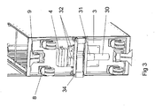
- a drive unit 3 For driving the conveyor belts 20, a drive unit 3 is provided. It comprises a motor 30, which acts via a gear 31 on two parallel drive rollers 32. To power the drive motor 30, an accumulator 4 is provided as energy storage.
- the accumulator 4 may be embodied, for example, in lithium-ion technology.
- a weight-saving alternative is to provide the accumulator 4 with high-capacity capacitors (so-called gold caps).
- the actuation is effected by means of an actuating unit 5, which is preferably arranged in a recess 15 at the edge of the cover plate 13 of the main body 1.
- the drive unit 3 is expediently arranged on the underside of the base 12.
- This arrangement has the advantage that it costs no storage space in the main body 1, that the drive there is also relatively protected between rollers 8, and that thanks to the low attachment results in a favorable effect on the center of gravity of the Serviertrolleys.
- the components of the drive unit 3 are covered by means of a housing, not shown.
- the drive rollers 32 Via the drive rollers 32, two drive belts 33 are guided, which extend over a deflection roller 34 in the region of the transition between the bottom 12 and side wall 11 between the side wall 11 and conveyor belt 20 upwards, where they are guided over a arranged on the top of the chassis 16 tension roller 35 are.
- the other portion of the Antriebriemens 33 extends over the tension roller 34 along the conveyor belt 20, on the underside of which it is attached.
- the drive of the conveyor belts 20 takes place in such a way that by the drive motor 30 via the gear 31 and the drive rollers 32, the drive belt 33 are moved so that the conveyor belt 20 is pushed in the upward movement and pulled in the downward movement.
- To achieve a high positioning accuracy of the drive belt 33 is designed as a toothed belt.
- the actuating unit 5 has a plurality of switches.
- an on / off switch 53 which is preferably provided with a light indicator for visualization of the on state.
- two directional switches 51, 52 are provided, upon actuation of which the conveyor belt 20 is moved in the conveying direction upwards or in the opposite direction.
- the actuator unit 5 includes an indexing device (not shown) which, when the switches 51, 52 are actuated, drives the drive motor 30 in the desired direction until the conveyor belt 20 has been raised or lowered by a distance corresponding to the distance between two adjacent receiving elements 21.
- the drive belt 33 has a plurality of through holes, which are scanned by means of a light barrier. The holes are evenly spaced. Their number corresponds the number of receiving strips 21 on the conveyor belts plus indexing openings for the end positions.
- a switch 54 is provided in order to quickly move the conveyor belts 20 down after complete unloading of the serving roll. If it is actuated, the conveyor belt 20 is moved so far down regardless of the indexing device until its limit switch (not shown) reports reaching the lower position.
- an upper limit switch is further provided. It serves to prevent an abutment or penetration of the uppermost tray in the folding space 19.
- a donor can preferably be provided a light barrier, a flat-acting line scan camera or a mechanically acting baffle plate.
- a marking opening may be provided on the drive belt 33, which is scanned by means of a light barrier preferably arranged on the bottom 12. This arrangement has the advantage of a particularly compact arrangement in which as many components as possible are arranged on the floor 12.
- a separate input device can be provided for the indexing device. About this is set whether normal high trays are arranged on each of the receiving elements 21, or whether excessive trays are provided, in which only each second or third receiving element 21 is provided with a tray. In this case, the indexing device controls the drive 3 in such a way that the same distance is traveled by a correspondingly increased distance.
Landscapes
- Engineering & Computer Science (AREA)
- Aviation & Aerospace Engineering (AREA)
- Handcart (AREA)
- Structure Of Belt Conveyors (AREA)
- Body Structure For Vehicles (AREA)
- Loading Or Unloading Of Vehicles (AREA)
Priority Applications (4)
| Application Number | Priority Date | Filing Date | Title |
|---|---|---|---|
| ES05000953T ES2293393T3 (es) | 2005-01-18 | 2005-01-18 | Carrito de sevicio para cabinas de pasajeros. |
| EP05000953A EP1681237B1 (fr) | 2005-01-18 | 2005-01-18 | Chariot de service pour des cabines de passagers |
| DE502005001419T DE502005001419D1 (de) | 2005-01-18 | 2005-01-18 | Serviertrolley für Passagierkabinen |
| AT05000953T ATE372259T1 (de) | 2005-01-18 | 2005-01-18 | Serviertrolley für passagierkabinen |
Applications Claiming Priority (1)
| Application Number | Priority Date | Filing Date | Title |
|---|---|---|---|
| EP05000953A EP1681237B1 (fr) | 2005-01-18 | 2005-01-18 | Chariot de service pour des cabines de passagers |
Publications (2)
| Publication Number | Publication Date |
|---|---|
| EP1681237A1 true EP1681237A1 (fr) | 2006-07-19 |
| EP1681237B1 EP1681237B1 (fr) | 2007-09-05 |
Family
ID=34933360
Family Applications (1)
| Application Number | Title | Priority Date | Filing Date |
|---|---|---|---|
| EP05000953A Expired - Lifetime EP1681237B1 (fr) | 2005-01-18 | 2005-01-18 | Chariot de service pour des cabines de passagers |
Country Status (4)
| Country | Link |
|---|---|
| EP (1) | EP1681237B1 (fr) |
| AT (1) | ATE372259T1 (fr) |
| DE (1) | DE502005001419D1 (fr) |
| ES (1) | ES2293393T3 (fr) |
Cited By (4)
| Publication number | Priority date | Publication date | Assignee | Title |
|---|---|---|---|---|
| NL1038222C2 (en) * | 2010-09-06 | 2012-03-07 | Promolding B V | Trolley. |
| WO2014205082A1 (fr) * | 2013-06-18 | 2014-12-24 | B/E Aerospace, Inc. | Porte de baie de chariot d'office d'aéronef |
| CN108402710A (zh) * | 2018-03-05 | 2018-08-17 | 温州金点知识产权顾问有限公司 | 商标档案归集存储柜 |
| EP4095038A1 (fr) * | 2021-05-28 | 2022-11-30 | Airbus Operations GmbH | Système de transport pour supports d'aliment dans un moyen de transport |
Families Citing this family (1)
| Publication number | Priority date | Publication date | Assignee | Title |
|---|---|---|---|---|
| CN109071024A (zh) * | 2016-05-04 | 2018-12-21 | 塞尔有限责任公司 | 用于飞行器的机载厨房的储物格装置和储物格系统 |
Citations (3)
| Publication number | Priority date | Publication date | Assignee | Title |
|---|---|---|---|---|
| EP0546968A1 (fr) * | 1991-12-12 | 1993-06-16 | René Grandi | Dispositif de distribution de plateaux-repas avec réfrigération et système d'introduction ou d'évacuation des plateaux et système de fermeture du module technique |
| FR2771393A1 (fr) * | 1997-11-26 | 1999-05-28 | Antoine Jean Voigt | Distibuteur automatique de plateaux repas,plateaux petits dejeuners,alimentaires,realisant a la fois le stockage et la distribution. |
| EP1101433A1 (fr) * | 1999-11-17 | 2001-05-23 | Blanco GmbH & Co. KG | Dispositif pour rechauffer de la nourriture |
-
2005
- 2005-01-18 ES ES05000953T patent/ES2293393T3/es not_active Expired - Lifetime
- 2005-01-18 EP EP05000953A patent/EP1681237B1/fr not_active Expired - Lifetime
- 2005-01-18 DE DE502005001419T patent/DE502005001419D1/de not_active Expired - Fee Related
- 2005-01-18 AT AT05000953T patent/ATE372259T1/de not_active IP Right Cessation
Patent Citations (3)
| Publication number | Priority date | Publication date | Assignee | Title |
|---|---|---|---|---|
| EP0546968A1 (fr) * | 1991-12-12 | 1993-06-16 | René Grandi | Dispositif de distribution de plateaux-repas avec réfrigération et système d'introduction ou d'évacuation des plateaux et système de fermeture du module technique |
| FR2771393A1 (fr) * | 1997-11-26 | 1999-05-28 | Antoine Jean Voigt | Distibuteur automatique de plateaux repas,plateaux petits dejeuners,alimentaires,realisant a la fois le stockage et la distribution. |
| EP1101433A1 (fr) * | 1999-11-17 | 2001-05-23 | Blanco GmbH & Co. KG | Dispositif pour rechauffer de la nourriture |
Cited By (7)
| Publication number | Priority date | Publication date | Assignee | Title |
|---|---|---|---|---|
| NL1038222C2 (en) * | 2010-09-06 | 2012-03-07 | Promolding B V | Trolley. |
| WO2012033402A1 (fr) * | 2010-09-06 | 2012-03-15 | Promolding B.V. | Chariot |
| WO2014205082A1 (fr) * | 2013-06-18 | 2014-12-24 | B/E Aerospace, Inc. | Porte de baie de chariot d'office d'aéronef |
| US9889935B2 (en) | 2013-06-18 | 2018-02-13 | B/E Aerospace, Inc. | Aircraft galley cart bay door |
| CN108402710A (zh) * | 2018-03-05 | 2018-08-17 | 温州金点知识产权顾问有限公司 | 商标档案归集存储柜 |
| CN108402710B (zh) * | 2018-03-05 | 2020-02-14 | 温州金点知识产权顾问有限公司 | 商标档案归集存储柜 |
| EP4095038A1 (fr) * | 2021-05-28 | 2022-11-30 | Airbus Operations GmbH | Système de transport pour supports d'aliment dans un moyen de transport |
Also Published As
| Publication number | Publication date |
|---|---|
| ATE372259T1 (de) | 2007-09-15 |
| DE502005001419D1 (de) | 2007-10-18 |
| ES2293393T3 (es) | 2008-03-16 |
| EP1681237B1 (fr) | 2007-09-05 |
Similar Documents
| Publication | Publication Date | Title |
|---|---|---|
| DE102004014745B4 (de) | Frachtdeck | |
| DE102013111570B4 (de) | Roboterzellenanordnung | |
| AT500229A1 (de) | Rechnergesteuerte transportvorrichtung | |
| DE2162042B2 (de) | Be- und entladevorrichtung fuer ein frachtlagerabteil eines flugzeugs | |
| DE102009049563A1 (de) | Shuttle-Kanallager, Shuttle-Bahnhof, Shuttle und Verfahren zum Betreiben des Shuttle-Kanallagers | |
| DE202008018037U1 (de) | Handhabungsvorrichtung für Stückgut, insbesondere Flugfracht | |
| EP1681237B1 (fr) | Chariot de service pour des cabines de passagers | |
| DE102015121846A1 (de) | Transportfahrzeug für Container | |
| EP3053838A1 (fr) | Dispositif modulaire d'emballage de cigarettes ou de paquets de cigarettes | |
| DE202017004863U1 (de) | Anlage zum Lagern und Transportieren von Paletten | |
| DE102004002548B3 (de) | Wechseleinheit für die Batterie eines Flurförderzeugs | |
| DE102015115323A1 (de) | Regalbediengerät | |
| DE2321543B2 (de) | Etagen-backofen | |
| EP3623310A1 (fr) | Conteneur de transport | |
| WO2015110636A1 (fr) | Meuble fonctionnel et véhicule, notamment aéronef | |
| DE102013010455B4 (de) | Verfahren zum Herstellen einer Sicherheitsplattform | |
| WO2001056905A1 (fr) | Systeme d'entrainement pour dispositif de stockage | |
| DE102014114011B4 (de) | Transportfahrzeug zum Transport von Produkten, insbesondere Kühlgut oder Medikamenten | |
| DE3630718C2 (fr) | ||
| DE4420512A1 (de) | Sortier- und Stapelanlage für Plattenaufteileinrichtungen | |
| EP3246211A1 (fr) | Marchepied escamotable pour un vehicule, en particulier un vehicule ferroviaire | |
| EP3141125A1 (fr) | Four a etages comprenant un chariot de chargement | |
| DE3921105A1 (de) | Fahrbarer warenbehaelter | |
| EP3494808A1 (fr) | Dispositif de fabrication d'articles à fumer | |
| DE102013103195A1 (de) | Transportfahrzeug |
Legal Events
| Date | Code | Title | Description |
|---|---|---|---|
| PUAI | Public reference made under article 153(3) epc to a published international application that has entered the european phase |
Free format text: ORIGINAL CODE: 0009012 |
|
| AK | Designated contracting states |
Kind code of ref document: A1 Designated state(s): AT BE BG CH CY CZ DE DK EE ES FI FR GB GR HU IE IS IT LI LT LU MC NL PL PT RO SE SI SK TR |
|
| AX | Request for extension of the european patent |
Extension state: AL BA HR LV MK YU |
|
| 17P | Request for examination filed |
Effective date: 20070119 |
|
| GRAP | Despatch of communication of intention to grant a patent |
Free format text: ORIGINAL CODE: EPIDOSNIGR1 |
|
| AKX | Designation fees paid |
Designated state(s): AT BE BG CH CY CZ DE DK EE ES FI FR GB GR HU IE IS IT LI LT LU MC NL PL PT RO SE SI SK TR |
|
| GRAS | Grant fee paid |
Free format text: ORIGINAL CODE: EPIDOSNIGR3 |
|
| GRAA | (expected) grant |
Free format text: ORIGINAL CODE: 0009210 |
|
| AK | Designated contracting states |
Kind code of ref document: B1 Designated state(s): AT BE BG CH CY CZ DE DK EE ES FI FR GB GR HU IE IS IT LI LT LU MC NL PL PT RO SE SI SK TR |
|
| REG | Reference to a national code |
Ref country code: GB Ref legal event code: FG4D Free format text: NOT ENGLISH |
|
| REG | Reference to a national code |
Ref country code: CH Ref legal event code: EP |
|
| REF | Corresponds to: |
Ref document number: 502005001419 Country of ref document: DE Date of ref document: 20071018 Kind code of ref document: P |
|
| REG | Reference to a national code |
Ref country code: IE Ref legal event code: FG4D Free format text: LANGUAGE OF EP DOCUMENT: GERMAN |
|
| REG | Reference to a national code |
Ref country code: CH Ref legal event code: NV Representative=s name: TROESCH SCHEIDEGGER WERNER AG |
|
| GBT | Gb: translation of ep patent filed (gb section 77(6)(a)/1977) |
Effective date: 20071212 |
|
| PG25 | Lapsed in a contracting state [announced via postgrant information from national office to epo] |
Ref country code: FI Free format text: LAPSE BECAUSE OF FAILURE TO SUBMIT A TRANSLATION OF THE DESCRIPTION OR TO PAY THE FEE WITHIN THE PRESCRIBED TIME-LIMIT Effective date: 20070905 Ref country code: LT Free format text: LAPSE BECAUSE OF FAILURE TO SUBMIT A TRANSLATION OF THE DESCRIPTION OR TO PAY THE FEE WITHIN THE PRESCRIBED TIME-LIMIT Effective date: 20070905 |
|
| PG25 | Lapsed in a contracting state [announced via postgrant information from national office to epo] |
Ref country code: PL Free format text: LAPSE BECAUSE OF FAILURE TO SUBMIT A TRANSLATION OF THE DESCRIPTION OR TO PAY THE FEE WITHIN THE PRESCRIBED TIME-LIMIT Effective date: 20070905 |
|
| REG | Reference to a national code |
Ref country code: ES Ref legal event code: FG2A Ref document number: 2293393 Country of ref document: ES Kind code of ref document: T3 |
|
| REG | Reference to a national code |
Ref country code: IE Ref legal event code: FD4D |
|
| PG25 | Lapsed in a contracting state [announced via postgrant information from national office to epo] |
Ref country code: GR Free format text: LAPSE BECAUSE OF FAILURE TO SUBMIT A TRANSLATION OF THE DESCRIPTION OR TO PAY THE FEE WITHIN THE PRESCRIBED TIME-LIMIT Effective date: 20071206 |
|
| PGFP | Annual fee paid to national office [announced via postgrant information from national office to epo] |
Ref country code: ES Payment date: 20080125 Year of fee payment: 4 |
|
| EN | Fr: translation not filed | ||
| ET | Fr: translation filed | ||
| REG | Reference to a national code |
Ref country code: FR Ref legal event code: EERR Free format text: CORRECTION DE BOPI 08/18 - BREVETS EUROPEENS DONT LA TRADUCTION N A PAS ETE REMISE A L INPI. IL Y A LIEU DE SUPPRIMER : LA MENTION DE LA NON-REMISE. LA REMISE DE LA TRADUCTION EST PUBLIEE DANS LE PRESENT BOPI. |
|
| PG25 | Lapsed in a contracting state [announced via postgrant information from national office to epo] |
Ref country code: PT Free format text: LAPSE BECAUSE OF FAILURE TO SUBMIT A TRANSLATION OF THE DESCRIPTION OR TO PAY THE FEE WITHIN THE PRESCRIBED TIME-LIMIT Effective date: 20080206 Ref country code: SK Free format text: LAPSE BECAUSE OF FAILURE TO SUBMIT A TRANSLATION OF THE DESCRIPTION OR TO PAY THE FEE WITHIN THE PRESCRIBED TIME-LIMIT Effective date: 20070905 Ref country code: IE Free format text: LAPSE BECAUSE OF FAILURE TO SUBMIT A TRANSLATION OF THE DESCRIPTION OR TO PAY THE FEE WITHIN THE PRESCRIBED TIME-LIMIT Effective date: 20070905 Ref country code: IS Free format text: LAPSE BECAUSE OF FAILURE TO SUBMIT A TRANSLATION OF THE DESCRIPTION OR TO PAY THE FEE WITHIN THE PRESCRIBED TIME-LIMIT Effective date: 20080105 Ref country code: CZ Free format text: LAPSE BECAUSE OF FAILURE TO SUBMIT A TRANSLATION OF THE DESCRIPTION OR TO PAY THE FEE WITHIN THE PRESCRIBED TIME-LIMIT Effective date: 20070905 |
|
| PGFP | Annual fee paid to national office [announced via postgrant information from national office to epo] |
Ref country code: DE Payment date: 20080320 Year of fee payment: 4 |
|
| PG25 | Lapsed in a contracting state [announced via postgrant information from national office to epo] |
Ref country code: SE Free format text: LAPSE BECAUSE OF FAILURE TO SUBMIT A TRANSLATION OF THE DESCRIPTION OR TO PAY THE FEE WITHIN THE PRESCRIBED TIME-LIMIT Effective date: 20071205 Ref country code: RO Free format text: LAPSE BECAUSE OF FAILURE TO SUBMIT A TRANSLATION OF THE DESCRIPTION OR TO PAY THE FEE WITHIN THE PRESCRIBED TIME-LIMIT Effective date: 20070905 |
|
| PLBE | No opposition filed within time limit |
Free format text: ORIGINAL CODE: 0009261 |
|
| STAA | Information on the status of an ep patent application or granted ep patent |
Free format text: STATUS: NO OPPOSITION FILED WITHIN TIME LIMIT |
|
| BERE | Be: lapsed |
Owner name: EDAG-SIGMA CONCURRENT ENGINEERING G.M.B.H. Effective date: 20080131 |
|
| PG25 | Lapsed in a contracting state [announced via postgrant information from national office to epo] |
Ref country code: DK Free format text: LAPSE BECAUSE OF FAILURE TO SUBMIT A TRANSLATION OF THE DESCRIPTION OR TO PAY THE FEE WITHIN THE PRESCRIBED TIME-LIMIT Effective date: 20070905 |
|
| 26N | No opposition filed |
Effective date: 20080606 |
|
| PG25 | Lapsed in a contracting state [announced via postgrant information from national office to epo] |
Ref country code: MC Free format text: LAPSE BECAUSE OF NON-PAYMENT OF DUE FEES Effective date: 20080131 |
|
| PG25 | Lapsed in a contracting state [announced via postgrant information from national office to epo] |
Ref country code: EE Free format text: LAPSE BECAUSE OF FAILURE TO SUBMIT A TRANSLATION OF THE DESCRIPTION OR TO PAY THE FEE WITHIN THE PRESCRIBED TIME-LIMIT Effective date: 20070905 |
|
| PG25 | Lapsed in a contracting state [announced via postgrant information from national office to epo] |
Ref country code: BE Free format text: LAPSE BECAUSE OF NON-PAYMENT OF DUE FEES Effective date: 20080131 |
|
| PG25 | Lapsed in a contracting state [announced via postgrant information from national office to epo] |
Ref country code: AT Free format text: LAPSE BECAUSE OF NON-PAYMENT OF DUE FEES Effective date: 20080118 |
|
| PG25 | Lapsed in a contracting state [announced via postgrant information from national office to epo] |
Ref country code: SI Free format text: LAPSE BECAUSE OF FAILURE TO SUBMIT A TRANSLATION OF THE DESCRIPTION OR TO PAY THE FEE WITHIN THE PRESCRIBED TIME-LIMIT Effective date: 20070905 |
|
| PG25 | Lapsed in a contracting state [announced via postgrant information from national office to epo] |
Ref country code: CY Free format text: LAPSE BECAUSE OF FAILURE TO SUBMIT A TRANSLATION OF THE DESCRIPTION OR TO PAY THE FEE WITHIN THE PRESCRIBED TIME-LIMIT Effective date: 20070905 |
|
| PG25 | Lapsed in a contracting state [announced via postgrant information from national office to epo] |
Ref country code: BG Free format text: LAPSE BECAUSE OF FAILURE TO SUBMIT A TRANSLATION OF THE DESCRIPTION OR TO PAY THE FEE WITHIN THE PRESCRIBED TIME-LIMIT Effective date: 20071205 |
|
| REG | Reference to a national code |
Ref country code: CH Ref legal event code: PL |
|
| GBPC | Gb: european patent ceased through non-payment of renewal fee |
Effective date: 20090118 |
|
| NLV4 | Nl: lapsed or anulled due to non-payment of the annual fee |
Effective date: 20090801 |
|
| PG25 | Lapsed in a contracting state [announced via postgrant information from national office to epo] |
Ref country code: DE Free format text: LAPSE BECAUSE OF NON-PAYMENT OF DUE FEES Effective date: 20090801 Ref country code: LI Free format text: LAPSE BECAUSE OF NON-PAYMENT OF DUE FEES Effective date: 20090131 Ref country code: CH Free format text: LAPSE BECAUSE OF NON-PAYMENT OF DUE FEES Effective date: 20090131 |
|
| REG | Reference to a national code |
Ref country code: FR Ref legal event code: ST Effective date: 20091030 |
|
| PG25 | Lapsed in a contracting state [announced via postgrant information from national office to epo] |
Ref country code: NL Free format text: LAPSE BECAUSE OF NON-PAYMENT OF DUE FEES Effective date: 20090801 Ref country code: GB Free format text: LAPSE BECAUSE OF NON-PAYMENT OF DUE FEES Effective date: 20090118 |
|
| REG | Reference to a national code |
Ref country code: ES Ref legal event code: FD2A Effective date: 20090119 |
|
| PG25 | Lapsed in a contracting state [announced via postgrant information from national office to epo] |
Ref country code: FR Free format text: LAPSE BECAUSE OF NON-PAYMENT OF DUE FEES Effective date: 20090202 Ref country code: ES Free format text: LAPSE BECAUSE OF NON-PAYMENT OF DUE FEES Effective date: 20090119 |
|
| PG25 | Lapsed in a contracting state [announced via postgrant information from national office to epo] |
Ref country code: HU Free format text: LAPSE BECAUSE OF FAILURE TO SUBMIT A TRANSLATION OF THE DESCRIPTION OR TO PAY THE FEE WITHIN THE PRESCRIBED TIME-LIMIT Effective date: 20080306 Ref country code: LU Free format text: LAPSE BECAUSE OF NON-PAYMENT OF DUE FEES Effective date: 20080118 |
|
| PG25 | Lapsed in a contracting state [announced via postgrant information from national office to epo] |
Ref country code: TR Free format text: LAPSE BECAUSE OF FAILURE TO SUBMIT A TRANSLATION OF THE DESCRIPTION OR TO PAY THE FEE WITHIN THE PRESCRIBED TIME-LIMIT Effective date: 20070905 |
|
| PG25 | Lapsed in a contracting state [announced via postgrant information from national office to epo] |
Ref country code: IT Free format text: LAPSE BECAUSE OF NON-PAYMENT OF DUE FEES Effective date: 20080131 |
|
| PGFP | Annual fee paid to national office [announced via postgrant information from national office to epo] |
Ref country code: FR Payment date: 20080118 Year of fee payment: 4 |