EP1679669B1 - Automatic flat-article dispensing apparatus - Google Patents
Automatic flat-article dispensing apparatus Download PDFInfo
- Publication number
- EP1679669B1 EP1679669B1 EP06000117A EP06000117A EP1679669B1 EP 1679669 B1 EP1679669 B1 EP 1679669B1 EP 06000117 A EP06000117 A EP 06000117A EP 06000117 A EP06000117 A EP 06000117A EP 1679669 B1 EP1679669 B1 EP 1679669B1
- Authority
- EP
- European Patent Office
- Prior art keywords
- flat article
- suction port
- suction
- chamber
- flat
- Prior art date
- Legal status (The legal status is an assumption and is not a legal conclusion. Google has not performed a legal analysis and makes no representation as to the accuracy of the status listed.)
- Expired - Fee Related
Links
Images


Classifications
-
- G—PHYSICS
- G07—CHECKING-DEVICES
- G07F—COIN-FREED OR LIKE APPARATUS
- G07F11/00—Coin-freed apparatus for dispensing, or the like, discrete articles
- G07F11/02—Coin-freed apparatus for dispensing, or the like, discrete articles from non-movable magazines
- G07F11/04—Coin-freed apparatus for dispensing, or the like, discrete articles from non-movable magazines in which magazines the articles are stored one vertically above the other
- G07F11/14—Coin-freed apparatus for dispensing, or the like, discrete articles from non-movable magazines in which magazines the articles are stored one vertically above the other with means for raising the stack of articles to permit delivery of the topmost
-
- G—PHYSICS
- G07—CHECKING-DEVICES
- G07F—COIN-FREED OR LIKE APPARATUS
- G07F11/00—Coin-freed apparatus for dispensing, or the like, discrete articles
- G07F11/02—Coin-freed apparatus for dispensing, or the like, discrete articles from non-movable magazines
- G07F11/04—Coin-freed apparatus for dispensing, or the like, discrete articles from non-movable magazines in which magazines the articles are stored one vertically above the other
- G07F11/16—Delivery means
- G07F11/165—Delivery means using xyz-picker or multi-dimensional article picking arrangements
- G07F11/1657—Delivery means using xyz-picker or multi-dimensional article picking arrangements the picking arrangements using suction
Definitions
- the present invention relates to a dispensing apparatus which automatically sends flat articles one by one. Specifically, the present invention relates to an automatic dispensing apparatus which sends, one by one, relatively large and heavy flat articles storing compact disks (CD) or digital versatile disks (DVD).
- CD compact disks
- DVD digital versatile disks
- “Flat article(s)” used in the present specification includes a flat case encapsulating a disk which is a product, a flat article which is a product itself, and an article in which a flat article is covered by a film to which the flat article is attached.
- This technology is such that, after the top flat article of stacked flat articles is suctioned by a suction device, the flat article is conveyed by a conveyance device which is in contact with the flat article by suction.
- This apparatus is to send the stuck top flat article by means of the conveyance device, and, for example, can dispense a CD case, which has a CD therein and wrapped with a thin film, without damaging the CD case.
- the amount of air suctioned from an uncovered part of the opening increases at once, and the suction force to the flat article decreases drastically, whereby the flat article falls off the suction device, thus the flat article may not be transferred to the conveyance device in the next cycle.
- reinforcement of the suction device can be considered so that a flat article does not fall off the suction device, but it causes increase in the size of the apparatus and the consumption energy, thus this technology cannot be employed readily.
- the conveyance device may be able to convey without causing the flat article to incline, but this idea causes increase in the size of the apparatus and the cost, and thus cannot be employed readily.
- This sheet supply apparatus comprises a sheet stacking means on which a plurality of sheets can be stacked.
- a first air absorb means is arranged opposite to a sheet surface of a sheet stack rested on the sheet stacking means and is adapted to absorb a sheet by air suction.
- a second sheet absorb means is arranged at a tip end side of the sheet surface in a sheet convey direction and is adapted to absorb a tip end of the sheet by air suction.
- a convey means is provided for conveying the sheet absorbed by the first and second sheet absorb means.
- the first and second sheet absorb means are arranged such that they have a different distance from the sheet surface of the sheet stack rested on the sheet stacking means.
- a first object of the present invention is to provide an automatic dispensing apparatus which can dispense a relatively large and heavy flat article without damaging it.
- a second object of the present invention is to provide an automatic dispensing apparatus which can dispense a relatively large and heavy flat article, without increasing the size of the apparatus and significantly increasing the consumption energy.
- the present invention is configured as claimed in claim 1.
- the flat article is suctioned by suction airflow which is drawn into at least the first suction port and second suction port created in the suction device.
- the flat article is suctioned by at least the first suction port and second suction port which are arranged in a conveyance direction of the flat article.
- the flat article is moved by the conveyance device in the lateral direction with respect to the direction of the stack.
- the second suction port is covered by the flat article entirely, and thus has large suction force.
- the flat article is conveyed by the conveyance device in the lateral direction while being suctioned by the second suction port.
- the flat article is then sent to the next cycle.
- the flat article is suctioned by at least the second suction port, thus the flat article can be transferred to the next cycle securely.
- the suction device does not have to be increased in its size.
- the suction device since the suction device does not have to be powerful, the suction device can be achieved without significantly increasing the consumption energy and the cost.
- an equalizer box with a predetermined thickness which is sectioned by a partition wall in the lateral direction, comprises a first chamber and second chamber, an end face of the first chamber being the first suction port, and an end face of the second chamber being the second suction port, and a suction airflow generation device is attached to an opening opposite to the suction ports of the first chamber and the second chamber.
- the suction airflow generation device suctions air from the first suction port and the second suction port, which are sectioned by the partition wall, via the first chamber and the second chamber.
- suction negative pressure is equalized, whereby substantially equalized negative pressure is generated through out the entire surfaces of the suction ports.
- the flat article is suctioned by suction force which is substantially equalized throughout the entire surfaces of the suction ports.
- the flat article covers the entire region of the second suction port, thus the flat article is conveyed by the conveyance device to the next cycle, while being suctioned by the large suction force of the second suction port.
- the suction airflow generation device can be configured at low cost without increasing its size.
- the suction airflow generation device is an axial-flow fan which is rotated by an electric motor.
- the suction airflow generation device is an axial-flow fan which is rotated by an electric motor, there are advantages that the suction airflow generation device is not increased in its size and is inexpensive.
- an automatic flat-article dispensing apparatus comprising: a table which supports stacked flat articles; a suction port which is disposed over the table and faces the flat articles; a suction device which suctions the top flat article of the stacked flat articles by sucking air through the suction port; and a conveyance device which conveys the flat article sucked by the suction port in a lateral direction with respect to the direction of the stack, wherein an equalizer box with a predetermined thickness has a first chamber and second chamber which are sectioned by a partition wall in the lateral direction, an end face of the first chamber being the first suction port, an end face of the second chamber being the second chamber, and a suction airflow generation device is attached to an opening opposite to the suction ports of the first chamber and the second chamber.
- An automatic dispensing apparatus 102 for dispensing a flat article 100 for example, a CD case, has a dispensing portion 104 and a storage portion 106.
- the storage portion 106 is fixed to left and right side frames 112, 114 and a rear frame 116 which configure the dispensing portion 104, and a dispensing portion frame 120 is configured by a top plate 118.
- the dispensing portion frame 120 is detachably attached to right and left hold portion side frames 124, 126 provided in a base frame 122, and to a hold portion rear frame 128.
- the dispensing portion 104 has a suction device 130, lateral direction conveyance device 132, and a dispensing device 135.
- the suction device 130 has a function of suctioning the flat article 100 by means of suction airflow.
- the suction device 130 has a cylindrical equalizer box 134 and a suction airflow generation device 136.
- the equalizer box 134 is in a form of cylinder such that a hollow portion thereof extends in a vertical direction, and is integrally resin-molded with a base 138 which is attached substantially horizontally between the left side frame 112 and right side frame 114.
- the equalizer box 134 can be constructed separately from the base 138 and fixed to the base 138.
- the equalizer box 134 has a suction port 141, a lower end face of which is formed into a rectangle.
- the suction port 141 is divided into a first suction port 144 and a second suction port 146 by a thin conveyance direction partition wall 142 which intersects with a conveyance direction D of the lateral direction conveyance device 132 and extends in a direction perpendicular to the conveyance direction D.
- the equalizer box 134 has a predetermined thickness, a first chamber 148 having the first suction port 144 on an end face thereof, and a second chamber 150 having the second suction port 146 on an end face thereof.
- the first chamber 148 and the second chamber 150 have a predetermined capacity which is determined by an opening area of each of the chambers and the thickness of the equalizer box 134.
- the capacity can function as a cushion, whereby the flat article 100 can be prevented from being caused to fall by drastic decrease of the suction force.
- the dispensing device 135 is attached to the dispensing portion frames 112, 114.
- the conveyance direction partition wall 142 is reinforced by a thin partition wall 149 which extends in the conveyance direction at the center of the conveyance direction partition wall 142.
- the suction airflow generation device 136 generates airflow for suctioning from the first suction port 144 and the second suction port 146.
- the suction airflow generation device 136 has an axial-flow fan 152 which is rotated by a first electric motor 151 rotating around a substantially perpendicular axis of rotation.
- the axial-flow fan 152 is disposed inside a circular hole 156 of a casing 154, and is fixed to an output axis of the first motor 151, the output axis being fixed to a stay 158 on an upper surface of the casing 154.
- the axial-flow fan 152 is fixed to an upper surface of the equalizer box 134.
- the suction airflow generation device 136 is attached opposite an opening of the equalizer box 134 positioned opposite to the first suction port 144 which is the end face of the first chamber 148 and to the second suction port 146 which is the end face of the second chamber 150.
- the suction airflowgenerationdevice 136 suctions air from the suction ports 144 and 146.
- the air is introduced from the first suction port 144 and the second suction port 146 into the equalizer box 134, and airflow going upward is generated.
- the suction airflow generation device 136 can employ a system for generating suction airflow by means of an ejector effect.
- the suction airflow generation device 136 may cause the axial-flow fan 152 to rotate by means of an air motor.
- the lateral direction conveyance device 132 is described next.
- the lateral direction conveyance device 132 has a function of conveying the flat article 100, which is suctioned by the suction device 130, in a lateral direction, and sending it to the next cycle.
- the lateral direction conveyance device 132 is disposed inside the equalizer box 134.
- a circumferential surface of the lateral direction conveyance device 132 slightly protrudes downward from the first suction port 144 and the second suction port 146 in order to convey the flat article 100, which is suctioned by the first suctionport 144 and the second suctionport 146, to the dispensing device 135 which is in the next cycle.
- the lateral direction conveyance device 132 has a first roller device 160 disposed inside the first chamber 148 and a second roller device 162 disposed inside the second chamber 150.
- the first roller device 160 is configured by two rollers 174 which are fixed, at a predetermined interval, to rotating axes 172 which are horizontally attached to a side wall 170 of the equalizer box 134 in a rotatable fashion.
- the second roller device 162 has the same configuration as the first roller device 160.
- the first electric motor 151 is prevented from overheating, frictional contact between the article 100 and the lower end of the equalizer box 134 is avoided, and conveyance resistance of the flat article 100 is minimized.
- the lower end of the equalizer box 134 may be caused to contact with the flat article 100.
- Circumferential surfaces of the rollers 174 are covered with a rubber in order to minimize slippage with the flat article 100.
- the lateral direction conveyance device 132 can use a belt instead of the rollers to move the flat article in the direction of the dispensing device 135.
- the dispensing device 135 disposed laterally in the equalizer box 134 is explained next.
- the dispensing device 135 conveys the flat article 100, which is sent from the lateral direction conveyance device 132, to a dispensing port 178.
- the dispensing device 135 has a first nip and conveyance device 182 and a second nip and conveyance device 184 which are disposed along a dispensing path 186.
- the first nip and conveyance device 182 and the second nip and conveyance device 184 have the same configuration, thus the first nip and conveyance device 182 is mainly described.
- the first nip and conveyance device 182 has an upper roller device 188 disposed on an upper side of the dispensing path 186 of the flat article 100, and a lower roller 190 disposed on a lower side of same.
- the upper roller device 188 has a shaft 192 which is rotatably supported by the base 138, and rollers 194 which are fixed to the shaft 192 at a predetermined interval.
- Lower surfaces of the rollers 194 are installed so as to be located on the same horizontal line as the lower surfaces of the rollers 174 of the first roller device 160 and the second roller device 162 of the lateral direction conveyance device 132.
- the lower roller device 190 is attached to a support plate 200 which is disposed parallel with the base 13 at a predetermined interval in a lower part of the base 138.
- the lower roller device 190 can be rotated with respect to the support plate 200, and has a shaft 202 which is movable so as to separate from the dispensing path 186, and a roller 204 which is fixed to the shaft 202 at a predetermined interval.
- the rollers 204 are disposed opposite to the rollers 194 respectively.
- the second nip and conveyance device 184 also has the same configuration.
- the lower roller device 190 is elastically biased so as to protrude to the dispensing path 186, and nips the flat article 100 with the upper roller device 188 by means of predetermined force.
- a shutter 206 is attached to the side frames 112, 114 in an end portion of the dispensing path 186 in a pivotally operable fashion.
- the shutter 206 is regulated by a stopper (not shown) so as not to pivotally operate counterclockwise further than a state shown in Fig. 3 , and is pivotally operable clockwise by being pressed by the flat article 100.
- a driving device 210 of the lateral direction conveyance device 132 and the dispensing device 135 is described next with reference to Fig. 3 and Fig. 7 .
- Synchronous pulleys 212, 214, 216, and 218 with the same diameter are fixed respectively to left end portions at the rotating axes 172 of the first roller device 160 and the second roller device 162, as well as the shafts 202 of the first nip and conveyance device 182 and the second nip and conveyance device 184, the left end portions protruding from the wide wall 170.
- a speed reducer 220 is fixed to the base 138, and a pulley 224 having the same diameter as the above pulleys is fixed to an output axis 222 of the speed reducer 220.
- the speed reducer 220 is rotated by a second electric motor 226 fixed thereto.
- the pulleys 224, 214, and 216 are wound by a toothed belt 228.
- the belt 228 is provided with predetermined tension by a tensioner 230.
- the pulleys 212 and 214 are wound by a tooted belt 232 and are provided with predetermined tension by a tensioner 234.
- the pulleys 216 and 218 are wound by a tooted belt 236 and are provided with predetermined tension by a tensioner 238.
- the pulley 224 is rotated counterclockwise in Fig. 7 by rotation of the second motor 226 in a predetermined direction, whereby the pulleys 212, 214, 216, and 218, that is, the rollers 174, 204 are rotated in the same direction.
- a detection sensor 250 of the flat article 100 is attached to the partition wall 142, and a lower end of a contact 252 of the detection sensor is positioned lower than a lower surface of the roller 174.
- the detection sensor 250 is pressed by the contact 252 and thereby outputs a detection signal.
- the storage portion 106 of the flat article 100 is described next.
- the storage portion 106 has a storage chamber 260 which extends in a vertical direction, a table 262 which moves the flat article 100, and a moving device 264 of the table 262.
- the storage chamber 260 is a rectangular cylinder-shaped space surrounded by the hold portion side frames 124, 126, and 128, and extending vertically in a lower part of the suction device 130.
- a lower end portion of a door 266 is attached to the base frame 122 in a rotatable fashion, an upper end portion of same is rotatably attached to a stay 268 fixed to the side frame 124, and is locked to the side frame 126 by a lock device 270 in a position in which the storage chamber 260 is closed.
- the door 266 is opened and the flat article 100 stacked on the table 262.
- the table 262 is in a form of a rectangular plate, and is movable so as to approach or separate from the equalizer box 134 in a lower part of the equalizer box 134 inside the storage chamber 260.
- the table 262 is movable so as to approach or separate from the first suction port 144 and the second suction port 146 which are positioned in a vertical direction of the table 262.
- the table 262 is guided in an anteroposterior direction by guide rollers 274 which are attached so as to have a guide column 272 therebetween, the guide column 272 extending substantially vertically to surfaces in the side frames 124 and 126, and is guided in a longitudinal section by guide rollers 276 which are attached to both sides of the table 262.
- the table 262 has a function of moving the flat article 100.
- the moving device 264 is described next with reference to Fig. 4 and Fig. 7 .
- the moving device 264 has a driving device 280 and a transmitting device 282.
- the driving device 280 has a speed reducer 284 which is disposed laterally in the suction device 130 and attached to the base 138, a third electric motor 286 which is fixed to the speed reducer 284 and drives the speed reducer 284, a driving gear 288 which is fixed to an output axis 287 of the speed reducer 284, a fixed axis 290 which is fixed to the base 138, an intermediate gear 292 which is attached rotatably to the fixed axis 290 and engages with the driving gear 288, a fixed axis 294 which is fixed to the base 138, an intermediate gear 296 which is rotatably attached to the fixed axis 294, and a rotating axis 302 both end portions of which protrude from the side frames 124 and 126, respective end portions of which are fixed with a pinion gear 298, 300, and which has a driven gear 304 engaging with the intermediate gear 296.
- the driving device 280 has a function of causing the table 262 to approach or separate from the suction device 130 via the transmitting device 282.
- the transmitting device 282 is described next with reference to Fig 1 and Fig. 4 .
- the transmitting device 282 with the same configuration is disposed laterally in each of the side frames 124 and 126, and the transmitting device 282 on the left side is mainly described.
- a stay 310 which protrudes laterally from the table 262 is attached with a lower end of a flexible rack 312 by a pin 314 in a pivotable fashion.
- the rack 312 is molded with a flexible resin and thus has flexibility.
- the rack 312 is pressed, at the back thereof, by a pinch roller 320 which is rotatably supported by a fixed axis 318 protruding from the side frames 124 and 126 respectively, whereby engagement with the pinion gear 298 is supported.
- a leading end portion of the rack 312 is inserted into a pipe 322 in a form of an inverted character J, which is fixed to side faces of the side frames 124 and 126, and is then returned to the base frame 122 side.
- the transmitting device 282 By disposing the transmitting device 282 to have a shape of J or U by means of the flexible rack 312, a compact configuration of the transmitting device 282 can be created; which is suitable for miniaturazion.
- Guide rails 324 cross sections of which form an angle, and which are disposed at front and rear sides of the rack 312, is fixed to the side frames 124 and 126 at a predetermined interval.
- the rack 312 When the rack 312 is bent by at least a predetermined amount and contact with the guide rails 324, the rack 312 is prevented from being blocked by the guide rails 324 and further bent, in order to prevent buckling of the rack 312.
- the moving device 264 in the embodiment is a lifting device 326 since it moves the table 262 up and down.
- the moving device 264 may have a function of changing the distance between the suction device 130 and the flat article 100 to a predetermined distance.
- the moving device 264 may fix the table 262 to move the dispensing portion 104.
- the position of the dispensing port 178 is changed, thus it is preferred that the table 262 be moved.
- the driving device 280 and the transmitting device 282 can be integrated.
- the moving device 264 may be configured by laterally providing a linear motor or magnet plate in the base 138 and connecting the table to a coil plate.
- the above-described detection sensor 250 is described next with reference to Fig. 3 and Fig. 6 .
- Two of the detection sensors 250 are fixed to the base 138 at a predetermined interval, the base 138 being disposed horizontally.
- the contact 252 of the detection sensor 250 is disposed in a space in an upper portion of the storage chamber 260, and a lower end of the contact 252 is positioned lower than a lower end of the roller 174.
- the detection sensor 250 When the contact 252 is slightly lifted up by the flat article 100, the detection sensor 250 outputs an ON signal.
- the detection sensor 250 is attached so as to be able to adjust the position thereof in a vertical direction in Fig. 3 .
- the detection sensor 250 can use a sensor of other type such as a photoelectric sensor.
- a fall prevention device 330 for preventing the table 262 from falling is described next with reference to Fig. 3 and Fig. 7 .
- the fall prevention device 330 has a function of preventing the table 262 from falling rapidly by the weight of the flat article 100, when the transmitting device 282 is released from the driving device 280.
- This function is provided in order to prevent the flat article 100 from being damaged or the like by the rapid fall of the table.
- the fall prevention device 330 using a unidirectional torque limiter 332.
- the unidirectional torque limiter 332 has a function of having predetermined rotational resistance when an input axis receives a torque in a predetermined direction, and having almost no rotary resistance when the input axis receives a torque in an opposite direction.
- the unidirectional torque limiter 332 is provided in a fixed axis 334 protruding from the left side frame 112, in a pivotally operational fashion.
- a gear 338 is fixed to an input axis 336 of the torque limiter 332, and when the torque limiter 332 is pivotally operated counterclockwise in Fig. 7 , the gear 338 engages with the driven gear 304.
- the pin 344 which is fixed to the side face of the limiter 332, is held in a standby position SB so that the gear 338 is not caused to engage with the gear 304 by a stopper portion 342 of a control lever 340 which is slidably supported in a vertical direction by the side frame 112.
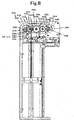
- Anotch 343 (see Fig. 8 ) is formed in an intermediate portion of the control lever 340 so as to be adjacent to the stopper portion 342.
- the notch 343 has a function of stopping rotation of the pin 344, and stopping rotation of the torque limiter 332 in a state in which the gear 338 engages with the driven gear 304.
- the unidirectional torque limiter 332 is preferably the one disclosed in, for example, Japanese Patent Application No. 3592948 .
- the position of the control lever 340 is switched between the standby position SB and an actuated position AP by a release mechanism 346.
- the release mechanism 346 of the lifting device 326 is described next with reference to Figs. 2 , 3 , and 7 .
- the release mechanism 346 has a release lever 348, a link lever 350, and a speed reducer frame 352.
- the release lever 348 is attached to a fixed axis 354 protruding from the speed reducer frame 352, in a pivotally operable fashion.
- the lever 350 is attached to a fixed axis 356 protruding from the side frame 112, in a pivotally operable fashion.
- the lever 350 is designed such that one end thereof is lifted up by the release lever 348.
- the other end of the lever 350 is link-coupled to the control lever 340 to move the control lever 340 in a vertical direction.
- the control lever 340 is guided by a guide, which is not shown, so as to move in a straight line in a vertical direction.
- a protrusion 358 and a locking concave portion 360 are formed in a lower portion of one end of the release lever 348, the protrusions 358 and the locking concave portion 360 being able to engage with a pin 362 which protrudes from the side frame 112.
- the speed reducer frame 352 is attached to a fixed axis 364 protruding from the side frame 112, in a pivotally operable fashion.
- release lever 348 is biased by a spring (not shown) counterclockwise in Fig. 7 .
- the release lever 348 is caused to pivotally operate clockwise in Fig. 7 , whereby the concave portion 360 is removed from the pin 362.
- the speed reducer frame 352 can be caused to pivotally operate clockwise around the fixed axis 364, whereby the driving gear 288 can be removed from the intermediate gear 292.
- the table 262 can be lifted down while receiving braking force of the unidirectional torque limiter 332 via the transmitting device 282.
- a dispense detection sensor 370 is described next with reference to Figs. 5 and 6 .
- the dispense detection sensor 370 has a function of detecting that a rear end of the flat article 100 passes the first nip and conveyance device 182.
- the dispense detection sensor 370 is fixed to an upper surface of the base 138, and a contact 372 of the dispense detection sensor is disposed between the rollers 194 and is lifted up by the flat article 100 passing the dispensing path 186, whereby an ON signal is output.
- the contact 372 protrudes to the dispensing path 186, and an OFF signal is output.
- the leading end of the flat article 100 protrudes from the dispensing port 178, and is then pulled, whereby the flat article 100 can be received.
- a flat article position control device 380 is described next with reference to Fig. 9 through Fig. 11 .
- the flat article position control device 380 is configured by a software, thus the control device is described with reference to Fig. 9 first.
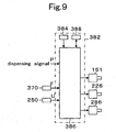
- a main control circuit 382 is, for example, a microprocessor in which predetermined processing is carried out while a CPU 386 exchange data with a RAM 388 on the basis of a program stored in a ROM 384.
- eachof the first electric motor 151, the second electric motor 226, and the third electric motor 286 is controlled on the basis of a dispense instruction signal P, an upper position signal U of the detection sensor 250, and a dispensing signal F of the dispense detection sensor 370.
- the pin 362 is engaged with the concave portion 360, and the driving gear 288 is engaged with the intermediate gear 292.
- control lever 340 is raised, and the gear 338 of the input axis 336 of the torque limiter 332 is removed from the driven gear 304 by the stopper portion 342.
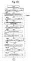
- Step S1 the dispense instruction signal P of the control device in an automatic vending machine is discriminated.
- Step S2 the process proceeds to Step S2, in which the third electric motor 286 of the moving device 264 is rotated reversely.
- the pinion gear 298 is rotated clockwise in Fig. 7 via the speed reducer 284, the intermediate gears 292, 296, and 304, and the rotating axis 302.
- Step S3 When the OFF signal is discriminated in Step S3 , the process to Step S4, in which the motor 286 is rotated normally after being stopped.
- Step S5 When the upper position signal U is judged in Step S5, the process proceeds to Step S6, in which the third motor 286 is stopped.
- the table 262 and thus the top flat article 100 are positioned slightly below a lower surfaces of the rollers 174 which are located immediately below at least the first suction port 144 and the second suction port 146.
- the table 262 and the flat article 100 are positioned in a place which is opposite the entire surfaces of the first suction port 144 and the second suction port 146 and in which the top flat article 100 is definitely suctioned by the suction airflow.
- Step S7 the first electric motor 151 of the suction airflow generation device 136 is rotated.
- the fan 152 By the rotation of the electric motor 151, the fan 152 is rotated, and the suction airflow for suctioning from the first suction port 144 and the second suction port 146 is generated.
- the top flat article 100 is suctioned by this suction airflow and is suctioned by the first suction port 144 and the second suction port 146.
- the top flat article 100 comes into contact with the lower surfaces of the first roller device 160 and the second roller device 162.
- Step S8 After time enough for suctioning is measured in Step S8, the process proceeds to Step S9.
- Step S9 the third motor 286 is cause to rotate reversely.
- the pinion gear 298 is rotated clockwise in Fig. 7 via the speed reducer 284, the driving gear 288, the intermediate gears 292, 296, and 304, and the rotating axis 302.
- the rack 312 is moved downward, and the table 262 and other flat article 100, besides the flat article 100 which is on the table 262 and suctioned by and attached to the suction port 141, fall at low speed.
- the suctioned flat article 100 and the other flat article 100 adhered underneath move downward along with the falling table 262, and only the suctioned flat article 100 is continuously suctioned by the first suction port 144 and the second suction port 146.
- the predetermined distance described above is a distance inwhich the top flat article 100 on the table 262 is not suctioned after the flat article 100 suctioned by the first suction port 144 and the second suction port 146 is sent out.
- Step S10 After time enough for this distant space is measured in Step S10, the rotation of the third motor 286 is stopped in Step S11.
- Step S12 the second electric motor 226 of the lateral direction conveyance device 132 is rotated.
- the rollers 174 of the lateral conveyance device 132 are rotated counterclockwise via the belt 228, the pulley 214, and the rotating axes 172, and the rollers 194 of the dispensing device 135 are rotated counterclockwise in Fig. 7 via the belt 288 and the pulley 216.
- the suctioned flat article 100 moved in a lateral direction to the left in Fig. 3 by frictionally contacting with the rollers 174, and is sent toward the dispensing device 135.
- the sent flat article 100 is nippedbetween the upper roller device 188 and the lower roller device 190 of the first nip and conveyance device 182 of the dispensing device 135, moved in the same direction, further nipped between the rollers of the second nip and conveyance device 184, and conveyed to the dispensing port 178.
- an opening area of the first suction port 144 gradually increases, and the suction force to the flat article 100 decreases drastically.
- the entire surface of the second suction port 146 is placed opposite the flat article 100, thus the flat article 100 is continuously suctioned by the second suction port 146.
- the flat article 100 is conveyed in a lateral direction while keeping its horizontal position.
- the leading end portion of the flat article 100 is regulated by the base 138 and the support plate 200.
- the leading end portion of the flat article 100 is regulated by the base 138 and the support plate 200, nipped between the upper roller device 188 and the lower roller device 190 of the first nip and conveyance device 182 so as to be held substantially horizontally, and continued to be conveyed in the lateral direction.
- the flat article 100 is then nipped in the second nip and conveyance device 184, and is further conveyed in the lateral direction.
- the leading end portion of the flat article 100 causes the shutter 206 to rotated clockwise, and protrudes from the dispensing port 178.
- the flat article 100 pushes the contact 372 up when passing the first nip and conveyance device 182, thus the dispense detection sensor 370 outputs the ON signal.
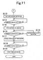
- Step S13 When the OFF signal is discriminated in Step S13, the process proceeds to Step S14.
- Step S14 the first electric motor 151 and the second electric motor 262 are stopped.
- the suction airflow generation device 136 is stopped, ad the suction function of the suction device 130 is stopped.
- the lateral direction conveyance device 132 and the dispensing device 135 are stopped.
- Step S15 it is discriminated whether the detection sensor 250 is an OFF signal or not.
- Step S16 in which the third motor 286 is operated reversely.
- the table 262 is lifted down via the rack 312 similarly.
- the flat article 100 By lifting down the table 262 and thus the flat article 100, the flat article 100 is prevented from being suctioned by the suction device 130 so that unnecessary dispensing is avoided.
- Step S17 the third electric motor 286 is operated normally, and the table 262 is raised.
- Step S18 in which when the upper position signal U, which is sent from the detection sensor 250 by the top flat article 100 pushing up the contact 252, is discriminated, the process proceeds to Step S19.
- Step S19 the third motor 286 is stopped, an optimal space of the top flat article 100 with respect to the first suction port 144 and the second suction port 146 is secured, and output of the next dispensing signal is waited.
- the lock device 270 is released, and the door 266 is opened as shown in Fig. 2 .
- the concave portion 360 moves to an upper portion of the pin 362, whereby the pin 362 can be pivotally operated clockwise in Fig. 7 .
- the speed reducer frame 352 is pivotally operated clockwise (see Fig. 8 ) until the protrusion 358 is blocked by the pin 362.
- one end of the link lever 350 is pivotally operated counterclockwise in Fig. 7 by an upper edge of the release lever 348, and the control lever 340 is moved downward.
- the notch 343 is placed opposite the pin 344 of the unidirectional torque limiter 332.
- the torque limiter 332 receives a torque counterclockwise from the spring, and thus is pivotally operated counterclockwise around the fixed axis 334 as a supporting point, and the gear 338 engages with the driven gear 304.
- the pin 344 is stopped by the notch 343, and the torque limiter 332 maintains this state. In other words, the torque limiter 332 is held in the actuated position AP.
- the torque limiter 332 is drive-coupled to the lifting device 326 (see Fig. 8 ).
- the table 262 tries to fall by means of the weights of the stacked flat articles 100, the table 262 receives the braking force by the resistance of the torque limiter 332.
- the table 262 falls at predetermined low speed until the lower end thereof is stopped by the base frame 122.
- the flat article 100 does not fall suddenly, and defects such as damage to the flat article 100 are not generated.
- the speed reducer frame 352 is pressed and pivotally operated counterclockwise, and the driving gear 288 is engaged with the intermediate gear 292.
- release lever 348 is pivotally operated counterclockwise, and the concave portion 360 engages with the pin 362.
- the gear 338 is removed from the driven gear 304, and the lifting device 326 is drive-coupled to the driving device 280 (see Fig. 7 ).
- Step S2 through the Step S11 explain the flat article position control device 380.
- the flat article position control device 380 has a function of separating the flat article 100 and the suction device 130 from each other, thereafter bringing the flat article 100 and the suction device 130 close to each other again so that the space between the flat article 100 and the suction device 130 becomes a predetermined space, thereafter suctioning the top flat article by means of the suction device 130, and then, again, separating the flat article 100 from the suction device 130.
- the flat article position control device 380 By configuring the flat article position control device 380 with a software, the components are not increased by a new component, thus the device can be created inexpensively.
- two equalizer boxes 134A and 134B are provided, and suction airflow generation devices 136A and 136B are coupled thereto respectively.
- the present invention has three or more suction ports. However, since the production cost of such configuration is high, it is preferred that one suction device be created, and a plurality of suction ports be formed for an equalizer box, as in Embodiment 1.
Description
- The present invention relates to a dispensing apparatus which automatically sends flat articles one by one. Specifically, the present invention relates to an automatic dispensing apparatus which sends, one by one, relatively large and heavy flat articles storing compact disks (CD) or digital versatile disks (DVD).
- "Flat article(s)" used in the present specification includes a flat case encapsulating a disk which is a product, a flat article which is a product itself, and an article in which a flat article is covered by a film to which the flat article is attached.
- The applicant of the present application has proposed a technology disclosed in
U.S. Patent Application No. 6311867 andJapanese Patent Application Laid-Open No. 2001-118137 - The summary of this technology is described hereinafter.
- This technology is such that, after the top flat article of stacked flat articles is suctioned by a suction device, the flat article is conveyed by a conveyance device which is in contact with the flat article by suction.
- This apparatus is to send the stuck top flat article by means of the conveyance device, and, for example, can dispense a CD case, which has a CD therein and wrapped with a thin film, without damaging the CD case.
- However, in the embodiments disclosed in above patent specifications, since there is only a suction port of a fan, which is the suction device, when dispensing relatively heavy flat article such as a CD case, the CD case which is suctioned by the suction port is moved in a lateral direction by the conveyance device, thus a part of the suction port is hidden by the flat particle.
- Accordingly, the amount of air suctioned from an uncovered part of the opening increases at once, and the suction force to the flat article decreases drastically, whereby the flat article falls off the suction device, thus the flat article may not be transferred to the conveyance device in the next cycle.
- Moreover, when the flat article is transferred to the conveyance device in the next cycle, only a leading end portion of the flat article is held by the conveyance device, and other portions fall off the suction port, thus the wrapping film may be damaged by scraping against a peripheral wall.
- Further, reinforcement of the suction device can be considered so that a flat article does not fall off the suction device, but it causes increase in the size of the apparatus and the consumption energy, thus this technology cannot be employed readily.
- Furthermore, even when the conveyance device receives only a part of the flat article in the next cycle, the conveyance device may be able to convey without causing the flat article to incline, but this idea causes increase in the size of the apparatus and the cost, and thus cannot be employed readily.
- In document
EP 0 598 272 A1 , a sheet supply apparatus is described. This sheet supply apparatus comprises a sheet stacking means on which a plurality of sheets can be stacked. A first air absorb means is arranged opposite to a sheet surface of a sheet stack rested on the sheet stacking means and is adapted to absorb a sheet by air suction. A second sheet absorb means is arranged at a tip end side of the sheet surface in a sheet convey direction and is adapted to absorb a tip end of the sheet by air suction. A convey means is provided for conveying the sheet absorbed by the first and second sheet absorb means. The first and second sheet absorb means are arranged such that they have a different distance from the sheet surface of the sheet stack rested on the sheet stacking means. - Further sheet supply apparatuses are described in
documents EP 1 001 389 A1 ,US-A-4,637,599 , andEP 1 247 771 A1 - A first object of the present invention is to provide an automatic dispensing apparatus which can dispense a relatively large and heavy flat article without damaging it.
- A second object of the present invention is to provide an automatic dispensing apparatus which can dispense a relatively large and heavy flat article, without increasing the size of the apparatus and significantly increasing the consumption energy.
- In order to achieve these objects, the present invention is configured as claimed in
claim 1. - In this configuration, the flat article is suctioned by suction airflow which is drawn into at least the first suction port and second suction port created in the suction device.
- In other words, the flat article is suctioned by at least the first suction port and second suction port which are arranged in a conveyance direction of the flat article.
- In this suction state, the flat article is moved by the conveyance device in the lateral direction with respect to the direction of the stack.
- By moving the flat article in the lateral direction, the first suction port which is covered by the flat article is no longer covered by the flat article gradually.
- Therefore, the suction force of the first suction port to the flat article, where a part of the first suction part is not covered, drastically decreases.
- However, the second suction port is covered by the flat article entirely, and thus has large suction force. The flat article is conveyed by the conveyance device in the lateral direction while being suctioned by the second suction port.
- The flat article is then sent to the next cycle.
- Therefore, while being sent to the next cycle, the flat article is suctioned by at least the second suction port, thus the flat article can be transferred to the next cycle securely.
- Moreover, with the simple structure having at least the first suction port and the second suction port, the suction device does not have to be increased in its size. In addition, since the suction device does not have to be powerful, the suction device can be achieved without significantly increasing the consumption energy and the cost.
- According to the present invention, an equalizer box with a predetermined thickness, which is sectioned by a partition wall in the lateral direction, comprises a first chamber and second chamber, an end face of the first chamber being the first suction port, and an end face of the second chamber being the second suction port, and a suction airflow generation device is attached to an opening opposite to the suction ports of the first chamber and the second chamber.
- Accordingly, the suction airflow generation device suctions air from the first suction port and the second suction port, which are sectioned by the partition wall, via the first chamber and the second chamber.
- At this moment, in the first chamber and the second chamber corresponding to the first suction port and the second suction port, suction negative pressure is equalized, whereby substantially equalized negative pressure is generated through out the entire surfaces of the suction ports.
- Therefore, the flat article is suctioned by suction force which is substantially equalized throughout the entire surfaces of the suction ports.
- When the flat article is moved by the conveyance device in the lateral direction, the flat article is removed from the first suction port first, and the suction force of the first suction port no longer acts in effect.
- However, since the flat article covers the entire region of the second suction port, thus the flat article is conveyed by the conveyance device to the next cycle, while being suctioned by the large suction force of the second suction port.
- Therefore, with the simple structure of the equalizer box which is sectioned in the lateral direction, at least the first suction port and the second suction port can be formed, thus the suction airflow generation device can be configured at low cost without increasing its size.
- According to the present invention the suction airflow generation device is an axial-flow fan which is rotated by an electric motor.
- Accordingly, since the suction airflow generation device is an axial-flow fan which is rotated by an electric motor, there are advantages that the suction airflow generation device is not increased in its size and is inexpensive.
- Further disclosed is an automatic flat-article dispensing apparatus, comprising: a table which supports stacked flat articles; a suction port which is disposed over the table and faces the flat articles; a suction device which suctions the top flat article of the stacked flat articles by sucking air through the suction port; and a conveyance device which conveys the flat article sucked by the suction port in a lateral direction with respect to the direction of the stack, wherein an equalizer box with a predetermined thickness has a first chamber and second chamber which are sectioned by a partition wall in the lateral direction, an end face of the first chamber being the first suction port, an end face of the second chamber being the second chamber, and a suction airflow generation device is attached to an opening opposite to the suction ports of the first chamber and the second chamber.
-
Fig. 1 is a perspective view which is viewed from upper left of an automatic flat-article dispensing apparatus according toEmbodiment 1. -
Fig. 2 is a perspective view which is viewed from upper right in a state in which a supplementary door of the automatic flat-article dispensing apparatus according to Embodiment 1 is opened. -
Fig. 3 is a cross-sectional view taken along a line A-A inFig. 5 . -
Fig. 4 is a perspective view which is viewed from an upper left portion in a state in which a left and upper part covers of the automatic flat-article dispensing apparatus according toEmbodiment 1 are removed. -
Fig. 5 is a cross-sectional view taken along a line B-B ofFig. 7 . -
Fig. 6 is a cross-sectional view taken along a line C-C ofFig. 7 . -
Fig. 7 is a left side view showing a state in which a left cover of the automatic flat-article dispensing apparatus according toEmbodiment 1 is removed. -
Fig. 8 is an explanatory diagram of an action of the automatic flat-article dispensing apparatus according toEmbodiment 1. -
Fig. 9 is a block diagram of a control device of the automatic flat-article dispensing apparatus according toEmbodiment 1. -
Fig. 10 andFig. 11 are flowcharts for explaining the action of the automatic flat-article dispensing apparatus according to Embodiment 1. -
Fig. 12 is an aspect in which two equalizer boxes are provided. - An
automatic dispensing apparatus 102 for dispensing aflat article 100, for example, a CD case, has a dispensingportion 104 and astorage portion 106. - The
storage portion 106 is fixed to left andright side frames rear frame 116 which configure the dispensingportion 104, and a dispensingportion frame 120 is configured by atop plate 118. - The dispensing
portion frame 120 is detachably attached to right and left holdportion side frames base frame 122, and to a hold portionrear frame 128. - Therefore, when the configuration units of the dispensing
portion 104 break down, it can be fixed by replacing with anew dispensing portion 104. - As shown in
Fig. 3 , the dispensingportion 104 has asuction device 130, lateraldirection conveyance device 132, and adispensing device 135. - First of all, the
suction device 130 is explained. - The
suction device 130 has a function of suctioning theflat article 100 by means of suction airflow. - The
suction device 130 has acylindrical equalizer box 134 and a suctionairflow generation device 136. - The
equalizer box 134 is in a form of cylinder such that a hollow portion thereof extends in a vertical direction, and is integrally resin-molded with abase 138 which is attached substantially horizontally between theleft side frame 112 andright side frame 114. However, theequalizer box 134 can be constructed separately from thebase 138 and fixed to thebase 138. - The
equalizer box 134 has asuction port 141, a lower end face of which is formed into a rectangle. - The
suction port 141 is divided into afirst suction port 144 and asecond suction port 146 by a thin conveyancedirection partition wall 142 which intersects with a conveyance direction D of the lateraldirection conveyance device 132 and extends in a direction perpendicular to the conveyance direction D. - In other words, the
equalizer box 134 has a predetermined thickness, afirst chamber 148 having thefirst suction port 144 on an end face thereof, and asecond chamber 150 having thesecond suction port 146 on an end face thereof. - The
first chamber 148 and thesecond chamber 150 have a predetermined capacity which is determined by an opening area of each of the chambers and the thickness of theequalizer box 134. - When the
first chamber 148 and thesecond chamber 150 have a predetermined capacity, even when the suction force of the suctionairflow generation device 136 fluctuates as time progresses, there is an advantage that the capacity can function as a cushion, whereby theflat article 100 can be prevented from being caused to fall by drastic decrease of the suction force. - The
dispensing device 135 is attached to the dispensing portion frames 112, 114. - It should be noted that, as shown in
Fig. 6 , the conveyancedirection partition wall 142 is reinforced by athin partition wall 149 which extends in the conveyance direction at the center of the conveyancedirection partition wall 142. - The suction
airflow generation device 136 generates airflow for suctioning from thefirst suction port 144 and thesecond suction port 146. - The suction
airflow generation device 136 has an axial-flow fan 152 which is rotated by a firstelectric motor 151 rotating around a substantially perpendicular axis of rotation. - The axial-
flow fan 152 is disposed inside acircular hole 156 of acasing 154, and is fixed to an output axis of thefirst motor 151, the output axis being fixed to astay 158 on an upper surface of thecasing 154. - The axial-
flow fan 152 is fixed to an upper surface of theequalizer box 134. - In other words, the suction
airflow generation device 136 is attached opposite an opening of theequalizer box 134 positioned opposite to thefirst suction port 144 which is the end face of thefirst chamber 148 and to thesecond suction port 146 which is the end face of thesecond chamber 150. The suction airflowgenerationdevice 136 suctions air from thesuction ports - As the axial-
flow fan 152 rotates, the air is introduced from thefirst suction port 144 and thesecond suction port 146 into theequalizer box 134, and airflow going upward is generated. - The suction
airflow generation device 136 can employ a system for generating suction airflow by means of an ejector effect. - Moreover, the suction
airflow generation device 136 may cause the axial-flow fan 152 to rotate by means of an air motor. - The lateral
direction conveyance device 132 is described next. - The lateral
direction conveyance device 132 has a function of conveying theflat article 100, which is suctioned by thesuction device 130, in a lateral direction, and sending it to the next cycle. - The lateral
direction conveyance device 132 is disposed inside theequalizer box 134. - A circumferential surface of the lateral
direction conveyance device 132 slightly protrudes downward from thefirst suction port 144 and thesecond suction port 146 in order to convey theflat article 100, which is suctioned by thefirst suctionport 144 and thesecond suctionport 146, to thedispensing device 135 which is in the next cycle. - In the embodiment, the lateral
direction conveyance device 132 has afirst roller device 160 disposed inside thefirst chamber 148 and asecond roller device 162 disposed inside thesecond chamber 150. - The
first roller device 160 is configured by tworollers 174 which are fixed, at a predetermined interval, to rotatingaxes 172 which are horizontally attached to aside wall 170 of theequalizer box 134 in a rotatable fashion. - The
second roller device 162 has the same configuration as thefirst roller device 160. - Therefore, lower portions of the
roller 174 slightly protrude from a lower end of theequalizer box 134. - For this reason, when the
flat article 100 is suctioned by thefirst suction port 144 and thesecond suction port 146, air is suctioned from a small space between the lower end of theequalizer box 134 and theflat article 100. - Accordingly, the first
electric motor 151 is prevented from overheating, frictional contact between thearticle 100 and the lower end of theequalizer box 134 is avoided, and conveyance resistance of theflat article 100 is minimized. - However, when the interval of time for conveying the
flat article 100 is long, the lower end of theequalizer box 134 may be caused to contact with theflat article 100. - Circumferential surfaces of the
rollers 174 are covered with a rubber in order to minimize slippage with theflat article 100. - The lateral
direction conveyance device 132 can use a belt instead of the rollers to move the flat article in the direction of thedispensing device 135. - The
dispensing device 135 disposed laterally in theequalizer box 134 is explained next. - The
dispensing device 135 conveys theflat article 100, which is sent from the lateraldirection conveyance device 132, to a dispensingport 178. - In the embodiment, the
dispensing device 135 has a first nip andconveyance device 182 and a second nip andconveyance device 184 which are disposed along a dispensingpath 186. - The first nip and
conveyance device 182 and the second nip andconveyance device 184 have the same configuration, thus the first nip andconveyance device 182 is mainly described. - The first nip and
conveyance device 182 has anupper roller device 188 disposed on an upper side of the dispensingpath 186 of theflat article 100, and alower roller 190 disposed on a lower side of same. - The
upper roller device 188 has ashaft 192 which is rotatably supported by thebase 138, androllers 194 which are fixed to theshaft 192 at a predetermined interval. - Lower portions of these
rollers 194 protrude from anopening 198 provided in the base 138 to the dispensingpath 186. - Lower surfaces of the
rollers 194 are installed so as to be located on the same horizontal line as the lower surfaces of therollers 174 of thefirst roller device 160 and thesecond roller device 162 of the lateraldirection conveyance device 132. - The
lower roller device 190 is attached to asupport plate 200 which is disposed parallel with the base 13 at a predetermined interval in a lower part of thebase 138. - The
lower roller device 190 can be rotated with respect to thesupport plate 200, and has ashaft 202 which is movable so as to separate from the dispensingpath 186, and aroller 204 which is fixed to theshaft 202 at a predetermined interval. - The
rollers 204 are disposed opposite to therollers 194 respectively. - The second nip and
conveyance device 184 also has the same configuration. - The
lower roller device 190 is elastically biased so as to protrude to the dispensingpath 186, and nips theflat article 100 with theupper roller device 188 by means of predetermined force. - A
shutter 206 is attached to the side frames 112, 114 in an end portion of the dispensingpath 186 in a pivotally operable fashion. - The
shutter 206 is regulated by a stopper (not shown) so as not to pivotally operate counterclockwise further than a state shown inFig. 3 , and is pivotally operable clockwise by being pressed by theflat article 100. - A driving device 210 of the lateral
direction conveyance device 132 and thedispensing device 135 is described next with reference toFig. 3 andFig. 7 . -
Synchronous pulleys rotating axes 172 of thefirst roller device 160 and thesecond roller device 162, as well as theshafts 202 of the first nip andconveyance device 182 and the second nip andconveyance device 184, the left end portions protruding from thewide wall 170. - As shown in
Fig. 3 , aspeed reducer 220 is fixed to thebase 138, and apulley 224 having the same diameter as the above pulleys is fixed to anoutput axis 222 of thespeed reducer 220. - The
speed reducer 220 is rotated by a secondelectric motor 226 fixed thereto. - The
pulleys toothed belt 228. - The
belt 228 is provided with predetermined tension by atensioner 230. - The
pulleys belt 232 and are provided with predetermined tension by atensioner 234. - The
pulleys belt 236 and are provided with predetermined tension by atensioner 238. - Therefore, the
pulley 224 is rotated counterclockwise inFig. 7 by rotation of thesecond motor 226 in a predetermined direction, whereby thepulleys rollers - Accordingly, the
flat article 100 which is in contact with each of therollers port 178. - A
detection sensor 250 of theflat article 100 is attached to thepartition wall 142, and a lower end of acontact 252 of the detection sensor is positioned lower than a lower surface of theroller 174. - Therefore, when the
flat article 100 approaches a predetermined distance, thedetection sensor 250 is pressed by thecontact 252 and thereby outputs a detection signal. - The
storage portion 106 of theflat article 100 is described next. - As shown in
Fig. 2 , thestorage portion 106 has astorage chamber 260 which extends in a vertical direction, a table 262 which moves theflat article 100, and a movingdevice 264 of the table 262. - The
storage chamber 260 is a rectangular cylinder-shaped space surrounded by the hold portion side frames 124, 126, and 128, and extending vertically in a lower part of thesuction device 130. - A lower end portion of a
door 266 is attached to thebase frame 122 in a rotatable fashion, an upper end portion of same is rotatably attached to astay 268 fixed to theside frame 124, and is locked to theside frame 126 by alock device 270 in a position in which thestorage chamber 260 is closed. - The
door 266 is opened and theflat article 100 stacked on the table 262. - The table 262 is in a form of a rectangular plate, and is movable so as to approach or separate from the
equalizer box 134 in a lower part of theequalizer box 134 inside thestorage chamber 260. - Specifically, the table 262 is movable so as to approach or separate from the
first suction port 144 and thesecond suction port 146 which are positioned in a vertical direction of the table 262. - In order to move smoothly, the table 262 is guided in an anteroposterior direction by
guide rollers 274 which are attached so as to have aguide column 272 therebetween, theguide column 272 extending substantially vertically to surfaces in the side frames 124 and 126, and is guided in a longitudinal section byguide rollers 276 which are attached to both sides of the table 262. - The table 262 has a function of moving the
flat article 100. - Therefore, other mechanisms can be employed as long as the table 262 has this function.
- The moving
device 264 is described next with reference toFig. 4 andFig. 7 . - The moving
device 264 has adriving device 280 and atransmitting device 282. - The
driving device 280 has aspeed reducer 284 which is disposed laterally in thesuction device 130 and attached to thebase 138, a thirdelectric motor 286 which is fixed to thespeed reducer 284 and drives thespeed reducer 284, adriving gear 288 which is fixed to anoutput axis 287 of thespeed reducer 284, afixed axis 290 which is fixed to thebase 138, anintermediate gear 292 which is attached rotatably to the fixedaxis 290 and engages with thedriving gear 288, afixed axis 294 which is fixed to thebase 138, anintermediate gear 296 which is rotatably attached to the fixedaxis 294, and arotating axis 302 both end portions of which protrude from the side frames 124 and 126, respective end portions of which are fixed with apinion gear gear 304 engaging with theintermediate gear 296. - The
driving device 280 has a function of causing the table 262 to approach or separate from thesuction device 130 via the transmittingdevice 282. - Therefore, other mechanisms can be employed as long as the
driving device 280 has this function. - The transmitting
device 282 is described next with reference toFig 1 andFig. 4 . - The transmitting
device 282 with the same configuration is disposed laterally in each of the side frames 124 and 126, and the transmittingdevice 282 on the left side is mainly described. - A
stay 310 which protrudes laterally from the table 262 is attached with a lower end of aflexible rack 312 by apin 314 in a pivotable fashion. - The
rack 312 is molded with a flexible resin and thus has flexibility. - An intermediate portion of the
rack 312 engages with thepinion gear 298. - The
rack 312 is pressed, at the back thereof, by apinch roller 320 which is rotatably supported by a fixedaxis 318 protruding from the side frames 124 and 126 respectively, whereby engagement with thepinion gear 298 is supported. - A leading end portion of the
rack 312 is inserted into apipe 322 in a form of an inverted character J, which is fixed to side faces of the side frames 124 and 126, and is then returned to thebase frame 122 side. - By disposing the transmitting
device 282 to have a shape of J or U by means of theflexible rack 312, a compact configuration of the transmittingdevice 282 can be created; which is suitable for miniaturazion. -
Guide rails 324, cross sections of which form an angle, and which are disposed at front and rear sides of therack 312, is fixed to the side frames 124 and 126 at a predetermined interval. - When the
rack 312 is bent by at least a predetermined amount and contact with theguide rails 324, therack 312 is prevented from being blocked by theguide rails 324 and further bent, in order to prevent buckling of therack 312. - The moving
device 264 in the embodiment is a lifting device 326 since it moves the table 262 up and down. - The moving
device 264 may have a function of changing the distance between thesuction device 130 and theflat article 100 to a predetermined distance. - Therefore, the moving
device 264 may fix the table 262 to move the dispensingportion 104. - However, when moving the dispensing
portion 104, the position of the dispensingport 178 is changed, thus it is preferred that the table 262 be moved. - Moreover, the driving
device 280 and the transmittingdevice 282 can be integrated. - For example, the moving
device 264 may be configured by laterally providing a linear motor or magnet plate in thebase 138 and connecting the table to a coil plate. - The above-described
detection sensor 250 is described next with reference toFig. 3 andFig. 6 . - Two of the
detection sensors 250 are fixed to the base 138 at a predetermined interval, thebase 138 being disposed horizontally. - The
contact 252 of thedetection sensor 250 is disposed in a space in an upper portion of thestorage chamber 260, and a lower end of thecontact 252 is positioned lower than a lower end of theroller 174. - When the
contact 252 is slightly lifted up by theflat article 100, thedetection sensor 250 outputs an ON signal. - At this moment, when the two
detection sensors 250 are switched ON, the positions of thecontacts 252 are determined such that the ON signal is output eventually. - Specifically, it is detected that the top
flat article 100 contacts the bothrollers 174 and is suctioned completely. - Further, the
detection sensor 250 is attached so as to be able to adjust the position thereof in a vertical direction inFig. 3 . - The
detection sensor 250 can use a sensor of other type such as a photoelectric sensor. - However, by using a mechanical sensor where the
contact 252 is used as in the embodiment, maintenance such as periodical cleaning does not need to be performed, thus a further inexpensive sensor, can be achieved. - A
fall prevention device 330 for preventing the table 262 from falling is described next with reference toFig. 3 andFig. 7 . - The
fall prevention device 330 has a function of preventing the table 262 from falling rapidly by the weight of theflat article 100, when the transmittingdevice 282 is released from the drivingdevice 280. - This function is provided in order to prevent the
flat article 100 from being damaged or the like by the rapid fall of the table. - It is preferred that the
fall prevention device 330 using aunidirectional torque limiter 332. - The
unidirectional torque limiter 332 has a function of having predetermined rotational resistance when an input axis receives a torque in a predetermined direction, and having almost no rotary resistance when the input axis receives a torque in an opposite direction. - Therefore, when the table 262 is lifted down in order to resupply the
flat article 100, predetermined rotational resistance is received from thetorque limiter 332, whereby the table 262 does not fall suddenly. Further, when the table 262 is lifted up by means of the driving device 2 8 0 and the transmittingdevice 282, drive resistance is not generated, whereby the drive energy is reduced. - The
unidirectional torque limiter 332 is provided in afixed axis 334 protruding from theleft side frame 112, in a pivotally operational fashion. - A
gear 338 is fixed to aninput axis 336 of thetorque limiter 332, and when thetorque limiter 332 is pivotally operated counterclockwise inFig. 7 , thegear 338 engages with the drivengear 304. - During the operation of the
automatic dispensing apparatus 102, thepin 344, which is fixed to the side face of thelimiter 332, is held in a standby position SB so that thegear 338 is not caused to engage with thegear 304 by astopper portion 342 of acontrol lever 340 which is slidably supported in a vertical direction by theside frame 112. - Anotch 343 (see
Fig. 8 ) is formed in an intermediate portion of thecontrol lever 340 so as to be adjacent to thestopper portion 342. - The
notch 343 has a function of stopping rotation of thepin 344, and stopping rotation of thetorque limiter 332 in a state in which thegear 338 engages with the drivengear 304. - The
unidirectional torque limiter 332 is preferably the one disclosed in, for example,Japanese Patent Application No. 3592948 - The position of the
control lever 340 is switched between the standby position SB and an actuated position AP by arelease mechanism 346. - The
release mechanism 346 of the lifting device 326 is described next with reference toFigs. 2 ,3 , and7 . - The
release mechanism 346 has arelease lever 348, alink lever 350, and aspeed reducer frame 352. - The
release lever 348 is attached to afixed axis 354 protruding from thespeed reducer frame 352, in a pivotally operable fashion. - The
lever 350 is attached to afixed axis 356 protruding from theside frame 112, in a pivotally operable fashion. - The
lever 350 is designed such that one end thereof is lifted up by therelease lever 348. - The other end of the
lever 350 is link-coupled to thecontrol lever 340 to move thecontrol lever 340 in a vertical direction. - The
control lever 340 is guided by a guide, which is not shown, so as to move in a straight line in a vertical direction. - A
protrusion 358 and a lockingconcave portion 360 are formed in a lower portion of one end of therelease lever 348, theprotrusions 358 and the lockingconcave portion 360 being able to engage with apin 362 which protrudes from theside frame 112. - The
speed reducer frame 352 is attached to afixed axis 364 protruding from theside frame 112, in a pivotally operable fashion. - It should be noted that the
release lever 348 is biased by a spring (not shown) counterclockwise inFig. 7 . - Therefore, by pressing a
pressed piece 366 of therelease lever 348, therelease lever 348 is caused to pivotally operate clockwise inFig. 7 , whereby theconcave portion 360 is removed from thepin 362. - Accordingly, the
speed reducer frame 352 can be caused to pivotally operate clockwise around the fixedaxis 364, whereby thedriving gear 288 can be removed from theintermediate gear 292. - When the
speed reducer frame 352 rotates by a predetermined amount, theprotrusion 358 is stopped by thepin 362, and the rotation of thespeed reducer frame 352 is stopped. - Therefore, in this state, the table 262 can be lifted down while receiving braking force of the
unidirectional torque limiter 332 via the transmittingdevice 282. - A dispense
detection sensor 370 is described next with reference toFigs. 5 and6 . - The dispense
detection sensor 370 has a function of detecting that a rear end of theflat article 100 passes the first nip andconveyance device 182. - On the basis of a passage detection signal of the dispense
detection sensor 370, the functions of the lateraldirection conveyance device 132 and thedispensing device 135 are stopped. In other words, the secondelectric motor 226 is stopped. - The dispense
detection sensor 370 is fixed to an upper surface of thebase 138, and acontact 372 of the dispense detection sensor is disposed between therollers 194 and is lifted up by theflat article 100 passing the dispensingpath 186, whereby an ON signal is output. When theflat article 100 passes, thecontact 372 protrudes to the dispensingpath 186, and an OFF signal is output. - When the rear end of the
flat article 100 passes thecontact 372, the leading end of theflat article 100 protrudes from the dispensingport 178, and is then pulled, whereby theflat article 100 can be received. - A flat article position control device 380 is described next with reference to
Fig. 9 through Fig. 11 . - In the present embodiment, the flat article position control device 380 is configured by a software, thus the control device is described with reference to
Fig. 9 first. - A
main control circuit 382 is, for example, a microprocessor in which predetermined processing is carried out while aCPU 386 exchange data with aRAM 388 on the basis of a program stored in aROM 384. - Specifically, actuationof eachof the first
electric motor 151, the secondelectric motor 226, and the thirdelectric motor 286 is controlled on the basis of a dispense instruction signal P, an upper position signal U of thedetection sensor 250, and a dispensing signal F of the dispensedetection sensor 370. - Actuation of the flat article position control device 380 is described next with reference to the flowcharts shown in
Figs. 10 and11 . - At the time of activation, the
pin 362 is engaged with theconcave portion 360, and thedriving gear 288 is engaged with theintermediate gear 292. - Therefore, the
control lever 340 is raised, and thegear 338 of theinput axis 336 of thetorque limiter 332 is removed from the drivengear 304 by thestopper portion 342. - In Step S1, the dispense instruction signal P of the control device in an automatic vending machine is discriminated.
- When the dispense instruction signal P is present, the process proceeds to Step S2, in which the third
electric motor 286 of the movingdevice 264 is rotated reversely. - By the rotation of the
motor 286, thepinion gear 298 is rotated clockwise inFig. 7 via thespeed reducer 284, theintermediate gears rotating axis 302. - Accordingly, the
rack 312 is moved downward, thus the table 262 and theflat article 100 on the table 262 move downward. - By this downward movement, the
contact 252, which is pushed up by theflat article 100, moves downward, and thedetection sensor 250 outputs an OFF signal. - When the OFF signal is discriminated in Step S3 , the process to Step S4, in which the
motor 286 is rotated normally after being stopped. - By this normal rotation, the
pinion gear 298 is rotated counterclockwise inFig. 7 , thus therack 312 move upward, and, as a result, the table 262 moves upward. - By this upward movement of the table 262, the
flat article 100 is lifted up and pushes up thecontact 252, whereby thedetection sensor 250 is switched ON and outputs the upper position signal U. - When the upper position signal U is judged in Step S5, the process proceeds to Step S6, in which the
third motor 286 is stopped. - Accordingly, the table 262, and thus the top
flat article 100 are positioned slightly below a lower surfaces of therollers 174 which are located immediately below at least thefirst suction port 144 and thesecond suction port 146. - In other words, the table 262 and the
flat article 100 are positioned in a place which is opposite the entire surfaces of thefirst suction port 144 and thesecond suction port 146 and in which the topflat article 100 is definitely suctioned by the suction airflow. - In Step S7, the first
electric motor 151 of the suctionairflow generation device 136 is rotated. - By the rotation of the
electric motor 151, thefan 152 is rotated, and the suction airflow for suctioning from thefirst suction port 144 and thesecond suction port 146 is generated. - The top
flat article 100 is suctioned by this suction airflow and is suctioned by thefirst suction port 144 and thesecond suction port 146. - In other words, the top
flat article 100 comes into contact with the lower surfaces of thefirst roller device 160 and thesecond roller device 162. - In this state, since a space is present between the upper surface of the
flat article 100 and thefirst suction port 144 andsecond suction port 146, the air is suctioned from the space, whereby predetermined suction force to theflat article 100 is maintained, and the airflow is caused to act on thefirst motor 151 and is then cooled off. - After time enough for suctioning is measured in Step S8, the process proceeds to Step S9.
- In Step S9 the
third motor 286 is cause to rotate reversely. - By the reverse rotation of the
third motor 286, thepinion gear 298 is rotated clockwise inFig. 7 via thespeed reducer 284, thedriving gear 288, theintermediate gears rotating axis 302. - Accordingly, the
rack 312 is moved downward, and the table 262 and otherflat article 100, besides theflat article 100 which is on the table 262 and suctioned by and attached to thesuction port 141, fall at low speed. - By this downward movement, the
flat article 100 which is suctioned by and attached to thefirst suction port 144 and thesecond suction port 146 is separated from the topflat article 100 on the table 262 by a predetermined distance. - Moreover, since the table 262 moves at low speed, adhesion force by the negative pressure is not generated between the table 262 and the suctioned
flat article 100. - Therefore, the suctioned
flat article 100 and the otherflat article 100 adhered underneath move downward along with the falling table 262, and only the suctionedflat article 100 is continuously suctioned by thefirst suction port 144 and thesecond suction port 146. - The predetermined distance described above is a distance inwhich the top
flat article 100 on the table 262 is not suctioned after theflat article 100 suctioned by thefirst suction port 144 and thesecond suction port 146 is sent out. - After time enough for this distant space is measured in Step S10, the rotation of the
third motor 286 is stopped in Step S11. - Accordingly, the distant space between the stuck
flat article 100 and the topflat article 100 on the table 262 is maintained. - Next, in Step S12, the second
electric motor 226 of the lateraldirection conveyance device 132 is rotated. - By the rotation of the second
electric motor 226, therollers 174 of thelateral conveyance device 132 are rotated counterclockwise via thebelt 228, thepulley 214, and therotating axes 172, and therollers 194 of thedispensing device 135 are rotated counterclockwise inFig. 7 via thebelt 288 and thepulley 216. - The suctioned
flat article 100 moved in a lateral direction to the left inFig. 3 by frictionally contacting with therollers 174, and is sent toward thedispensing device 135. - The sent
flat article 100 is nippedbetween theupper roller device 188 and thelower roller device 190 of the first nip andconveyance device 182 of thedispensing device 135, moved in the same direction, further nipped between the rollers of the second nip andconveyance device 184, and conveyed to the dispensingport 178. - In this process, a relative area of the
flat article 100 with respect tofirst suction port 144 becomes small gradually. - In other words, an opening area of the
first suction port 144 gradually increases, and the suction force to theflat article 100 decreases drastically. - However, the entire surface of the
second suction port 146 is placed opposite theflat article 100, thus theflat article 100 is continuously suctioned by thesecond suction port 146. - Therefore, the
flat article 100 is conveyed in a lateral direction while keeping its horizontal position. - Then, when the leading end of the
flat article 100 reaches immediately before the second nip andconveyance device 184, the rear portion of theflat article 100 starts to be removed from thesecond suction port 146, and the suction force to theflat article 100 decreases drastically. - However, the leading end portion of the
flat article 100 is regulated by thebase 138 and thesupport plate 200. - Therefore, when the rear end portion of the
flat article 100 falls off thesecond suctionport 146, the leading end portion of theflat article 100 is regulated by thebase 138 and thesupport plate 200, nipped between theupper roller device 188 and thelower roller device 190 of the first nip andconveyance device 182 so as to be held substantially horizontally, and continued to be conveyed in the lateral direction. - The
flat article 100 is then nipped in the second nip andconveyance device 184, and is further conveyed in the lateral direction. - Therefore, the leading end portion of the
flat article 100 causes theshutter 206 to rotated clockwise, and protrudes from the dispensingport 178. - The
flat article 100 pushes thecontact 372 up when passing the first nip andconveyance device 182, thus the dispensedetection sensor 370 outputs the ON signal. - When the rear end of the
flat article 100 passes the fist nip andconveyance device 182, thecontact 372 moves downward, and thedispenses detection sensor 370 outputs the OFF signal. - When the OFF signal is discriminated in Step S13, the process proceeds to Step S14.
- In Step S14 the first
electric motor 151 and the secondelectric motor 262 are stopped. - Specifically, the suction
airflow generation device 136 is stopped, ad the suction function of thesuction device 130 is stopped. - Moreover, the lateral
direction conveyance device 132 and thedispensing device 135 are stopped. - Next, in Step S15, it is discriminated whether the
detection sensor 250 is an OFF signal or not. - Specifically, it is judged whether the top
flat article 100 pushes up thecontact 252. - If the
detection sensor 250 outputs the upper position signal U, the process proceeds to Step S16, in which thethird motor 286 is operated reversely. - Accordingly, the table 262 is lifted down via the
rack 312 similarly. - Specifically, after the top
flat article 100 is dispensed, in the case in which the next topflat article 100 pushes up thecontact 252, there is a risk that this topflat article 100 is suctioned by the inertial operation of thesuction device 130, and conveyed to the dispensingport 178 by the inertial operation of the lateraldirection conveyance device 132. - By lifting down the table 262 and thus the
flat article 100, theflat article 100 is prevented from being suctioned by thesuction device 130 so that unnecessary dispensing is avoided. - Next, in Step S17, the third
electric motor 286 is operated normally, and the table 262 is raised. - The process proceeds to the next step S18, in which when the upper position signal U, which is sent from the
detection sensor 250 by the topflat article 100 pushing up thecontact 252, is discriminated, the process proceeds to Step S19. - In Step S19, the
third motor 286 is stopped, an optimal space of the topflat article 100 with respect to thefirst suction port 144 and thesecond suction port 146 is secured, and output of the next dispensing signal is waited. - Operation performed when resupplying
flat article 100 on the table 262 is described next. - First of all, the
lock device 270 is released, and thedoor 266 is opened as shown inFig. 2 . - Next, the pressed
piece 366 is pressed, and therelease lever 348 is pivotally operated clockwise inFig. 7 . - Accordingly, the
concave portion 360 moves to an upper portion of thepin 362, whereby thepin 362 can be pivotally operated clockwise inFig. 7 . - The
speed reducer frame 352 is pivotally operated clockwise (seeFig. 8 ) until theprotrusion 358 is blocked by thepin 362. - Accordingly, the
driving gear 288 is removed from thegear 292. - At the same time, one end of the
link lever 350 is pivotally operated counterclockwise inFig. 7 by an upper edge of therelease lever 348, and thecontrol lever 340 is moved downward. - Therefore, the
notch 343 is placed opposite thepin 344 of theunidirectional torque limiter 332. - The
torque limiter 332 receives a torque counterclockwise from the spring, and thus is pivotally operated counterclockwise around the fixedaxis 334 as a supporting point, and thegear 338 engages with the drivengear 304. - Furthermore, the
pin 344 is stopped by thenotch 343, and thetorque limiter 332 maintains this state. In other words, thetorque limiter 332 is held in the actuated position AP. - Therefore, the
torque limiter 332 is drive-coupled to the lifting device 326 (seeFig. 8 ). - Although the table 262 tries to fall by means of the weights of the stacked
flat articles 100, the table 262 receives the braking force by the resistance of thetorque limiter 332. - In other words, the table 262 falls at predetermined low speed until the lower end thereof is stopped by the
base frame 122. - Therefore, the
flat article 100 does not fall suddenly, and defects such as damage to theflat article 100 are not generated. - Thereafter, a new
flat article 100 is placed on the table 262, and thedoor 266 is closed and locked with thelock device 270. - Next, the
speed reducer frame 352 is pressed and pivotally operated counterclockwise, and thedriving gear 288 is engaged with theintermediate gear 292. - Accordingly, the
release lever 348 is pivotally operated counterclockwise, and theconcave portion 360 engages with thepin 362. - As a result, the
link lever 350 is rotated clockwise inFig. 8 by a biasing device, whereby thecontrol lever 340 is pulled upward, thepin 344 pressed by an inclined portion of thenotch 343, and thetorque limiter 332 operated pivotally clockwise. - Accordingly, the
gear 338 is removed from the drivengear 304, and the lifting device 326 is drive-coupled to the driving device 280 (seeFig. 7 ). - As is clear from the above explanation, Step S2 through the Step S11 explain the flat article position control device 380.
- Specifically, the flat article position control device 380 has a function of separating the
flat article 100 and thesuction device 130 from each other, thereafter bringing theflat article 100 and thesuction device 130 close to each other again so that the space between theflat article 100 and thesuction device 130 becomes a predetermined space, thereafter suctioning the top flat article by means of thesuction device 130, and then, again, separating theflat article 100 from thesuction device 130. - By configuring the flat article position control device 380 with a software, the components are not increased by a new component, thus the device can be created inexpensively.
- A further aspect is described next with reference to
Fig. 12 . - According to this aspect two
equalizer boxes airflow generation devices - It should be noted that the present invention has three or more suction ports. However, since the production cost of such configuration is high, it is preferred that one suction device be created, and a plurality of suction ports be formed for an equalizer box, as in
Embodiment 1.
Claims (1)
- An automatic flat-article dispensing apparatus, comprising:a table (262) which supports stacked flat articles (100) ;a suction port (141) which is disposed over the table (262) and faces the flat articles (100), and which comprises a first suction port (144) and a second suction port (146) which are disposed in a lateral direction with respect to the direction of the stack,a suction device (130) comprising a cylindrical equalizer box (134) and an axial-flow fan (152), wherein the suction device (130) suctions the top flat article of the stacked flat articles by sucking air through the suction port (141);a conveyance device (132) which conveys the flat article sucked via the suction port (141) in said lateral direction ; andthe axial-flow fan (152) which is disposed inside a circular hole (156) of a casing (154) and rotates by an electric motor (151) around an axis perpendicular to the lateral direction;characterized in that
the cylindrical equalizer box (134) extends in a vertical direction and is sectioned by a partitionwall (142) in the lateral direction into a first chamber (148) and a second chamber (150), wherein the partition wall (142) intersects with the lateral direction and extends in a direction perpendicular to the lateral direction, wherein the first chamber (148) and the second chamber (150) each have a predetermined capacity to prevent the flat article (100) from falling due to fluctuations of the suction force, and wherein a lower end face of the first chamber (148) is the first suction port (144), and a lower end face of the second chamber (150) is the second suction port (146);
in that said axial-flow fan (152) is attached to an upper opening of said equalizer box (134) opposite to the suction ports (144, 146) of the first chamber (148) and the second chamber (150) ;
and in that said conveyance device (132) is disposed inside said first chamber (148) and said second chamber (150), wherein a circumferential surface of said conveyance device (132) slightly protrudes from a lower end of the equalizer box (134), wherein when the flat article (100) is suctioned by the first suction port (144) and the second suction port (146), air is suctioned from a small space between the lower end of the equalizer box (134) and the flat article (100).
Applications Claiming Priority (1)
| Application Number | Priority Date | Filing Date | Title |
|---|---|---|---|
| JP2005000331A JP2006190366A (en) | 2005-01-05 | 2005-01-05 | Automatic delivery apparatus for flat article |
Publications (3)
| Publication Number | Publication Date |
|---|---|
| EP1679669A2 EP1679669A2 (en) | 2006-07-12 |
| EP1679669A3 EP1679669A3 (en) | 2006-09-06 |
| EP1679669B1 true EP1679669B1 (en) | 2008-07-09 |
Family
ID=36569940
Family Applications (1)
| Application Number | Title | Priority Date | Filing Date |
|---|---|---|---|
| EP06000117A Expired - Fee Related EP1679669B1 (en) | 2005-01-05 | 2006-01-04 | Automatic flat-article dispensing apparatus |
Country Status (4)
| Country | Link |
|---|---|
| US (1) | US7377507B2 (en) |
| EP (1) | EP1679669B1 (en) |
| JP (1) | JP2006190366A (en) |
| DE (1) | DE602006001654D1 (en) |
Families Citing this family (13)
| Publication number | Priority date | Publication date | Assignee | Title |
|---|---|---|---|---|
| CN1310769C (en) * | 2001-08-31 | 2007-04-18 | 精工爱普生株式会社 | Recording apparatus |
| EP1474774B1 (en) | 2002-02-15 | 2008-01-02 | Coinstar, Inc. | Apparatuses and methods for dispensing cards |
| US9233812B2 (en) * | 2005-12-05 | 2016-01-12 | Outerwall Inc. | Card dispensing apparatuses and associated methods of operation |
| DE102006008895B4 (en) * | 2006-02-19 | 2008-04-10 | Richter, Gerhard, Dipl.-Ing. (FH) | CD / DVD cases donors |
| JP5239035B2 (en) * | 2008-09-17 | 2013-07-17 | 旭精工株式会社 | Automatic dispensing device for flat goods |
| JP5294056B2 (en) * | 2008-09-17 | 2013-09-18 | 旭精工株式会社 | Lifting device driving device in automatic dispensing device for flat article |
| TWI367458B (en) * | 2008-12-31 | 2012-07-01 | Ind Tech Res Inst | Automatic card dispenser |
| WO2011019407A1 (en) * | 2009-08-12 | 2011-02-17 | Coinstar, Inc. | Card dispensing apparatuses and associated methods of operation |
| KR101297272B1 (en) * | 2009-12-18 | 2013-08-14 | 한국전자통신연구원 | The medicine taking support device and case discharging method thereof, and medicine taking support system and supporting method thereof |
| US8276741B1 (en) | 2010-10-06 | 2012-10-02 | Zittel Steven A | Bottle cap orienting apparatus |
| CN103303727B (en) * | 2012-03-16 | 2016-05-18 | 新雷欧电子(深圳)有限公司 | Card class dispensing device |
| US9227800B2 (en) | 2013-03-14 | 2016-01-05 | Outerwall Inc. | Multi-function card handling apparatus and methods of operation |
| US11950711B2 (en) * | 2022-08-24 | 2024-04-09 | Jiree (Hua'an) Technology Co., Ltd. | Automatic lifting display rack |
Family Cites Families (16)
| Publication number | Priority date | Publication date | Assignee | Title |
|---|---|---|---|---|
| FI71707C (en) * | 1984-10-12 | 1987-02-09 | Raute Oy | SUGLYFTTRANSPORTOER FOER FOERFLYTTNING AV ARKFORMIGA FOEREMAOL. |
| JPH0726276Y2 (en) * | 1988-05-09 | 1995-06-14 | 旭精工株式会社 | Card dispenser for card vending machines |
| US5478066A (en) * | 1992-11-02 | 1995-12-26 | Canon Kabushiki Kaisha | Sheet supply apparatus |
| DE4410384C1 (en) * | 1994-03-25 | 1995-05-24 | Roland Man Druckmasch | Control for stack lift device |
| JP3620198B2 (en) * | 1997-02-21 | 2005-02-16 | 株式会社日立製作所 | Paper sheet separator |
| US6102248A (en) * | 1997-07-23 | 2000-08-15 | Asahi Seiko Co., Ltd. | Card type structures |
| JP2000128372A (en) * | 1998-10-27 | 2000-05-09 | Matsushita Electric Works Ltd | Separating and carrying device for sheet material |
| JP3903118B2 (en) * | 1998-11-16 | 2007-04-11 | 旭精工株式会社 | Card body dispensing device |
| JP2000177865A (en) * | 1998-12-14 | 2000-06-27 | Canon Inc | Sheet feeder and image forming device with the same |
| JP3592948B2 (en) | 1999-02-17 | 2004-11-24 | 株式会社日立製作所 | Electric vehicle and permanent magnet rotating electric machine used therefor |
| JP2001084423A (en) * | 1999-09-09 | 2001-03-30 | Asahi Seiko Kk | Device for extracting paper money |
| JP4092450B2 (en) * | 1999-10-20 | 2008-05-28 | 旭精工株式会社 | Elevating device for card body and card body dispensing device provided with the elevating device |
| ES2230241T3 (en) * | 2001-04-03 | 2005-05-01 | Mars Incorporated | DEVICE FOR STORAGE OF BANK TICKETS. |
| TW587221B (en) * | 2002-03-11 | 2004-05-11 | Asahi Seiko Co Ltd | An automatic dispensing machine of good like sheet |
| JP4374523B2 (en) * | 2003-06-30 | 2009-12-02 | 旭精工株式会社 | Automatic dispensing device for sheet-like products |
| JP4423368B2 (en) * | 2003-12-19 | 2010-03-03 | 旭精工株式会社 | Card-like product automatic dispensing device and method thereof |
-
2005
- 2005-01-05 JP JP2005000331A patent/JP2006190366A/en active Pending
-
2006
- 2006-01-04 EP EP06000117A patent/EP1679669B1/en not_active Expired - Fee Related
- 2006-01-04 US US11/325,103 patent/US7377507B2/en active Active
- 2006-01-04 DE DE602006001654T patent/DE602006001654D1/en active Active
Also Published As
| Publication number | Publication date |
|---|---|
| JP2006190366A (en) | 2006-07-20 |
| DE602006001654D1 (en) | 2008-08-21 |
| EP1679669A2 (en) | 2006-07-12 |
| EP1679669A3 (en) | 2006-09-06 |
| US20060145411A1 (en) | 2006-07-06 |
| US7377507B2 (en) | 2008-05-27 |
Similar Documents
| Publication | Publication Date | Title |
|---|---|---|
| EP1679669B1 (en) | Automatic flat-article dispensing apparatus | |
| TWI568658B (en) | Card delivery device and card issuance recovery device | |
| US7152531B2 (en) | Interleaf removal apparatus, plate feed apparatus and image recording system | |
| KR100506879B1 (en) | Elevator for card and dispenser for the same | |
| JP4374523B2 (en) | Automatic dispensing device for sheet-like products | |
| JP2004102626A (en) | Housing device driving device for bill receiving and housing device | |
| US6981698B2 (en) | Automatic dispensing machine of substantially flat goods | |
| JP4048248B2 (en) | Automatic dispensing device for sheet-like products | |
| JP2003248855A (en) | Paper sheet processing device | |
| JP4461248B2 (en) | Automatic delivery method for sheet-like product in automatic delivery device for sheet-like product | |
| JP3865804B2 (en) | Connection structure of sheet transport device | |
| JP4210726B2 (en) | Automatic dispensing device for sheet-like products | |
| JP4050957B2 (en) | Banknote storage device | |
| JPH0743089Y2 (en) | Paper sheet collection device | |
| JP4092450B2 (en) | Elevating device for card body and card body dispensing device provided with the elevating device | |
| JP3469931B2 (en) | Paper ejection device | |
| JP4296340B2 (en) | Automatic dispensing device for sheet-like bags containing products | |
| JP5239035B2 (en) | Automatic dispensing device for flat goods | |
| US20160133084A1 (en) | Pharmaceutical dispensing unit, pharmaceutical dispensing apparatus equipped with same, and method for controlling pharmaceutical dispensing apparatus | |
| JP4465632B2 (en) | Card body dispensing device | |
| JP5870338B2 (en) | Sheet-like product dispensing device | |
| JP2004103041A (en) | Paper sheets dispenser | |
| JP2010072802A5 (en) | ||
| JP2004145895A (en) | Paper sheet dispenser | |
| JPH10293818A (en) | Card discharge device |
Legal Events
| Date | Code | Title | Description |
|---|---|---|---|
| PUAI | Public reference made under article 153(3) epc to a published international application that has entered the european phase |
Free format text: ORIGINAL CODE: 0009012 |
|
| AK | Designated contracting states |
Kind code of ref document: A2 Designated state(s): AT BE BG CH CY CZ DE DK EE ES FI FR GB GR HU IE IS IT LI LT LU LV MC NL PL PT RO SE SI SK TR |
|
| AX | Request for extension of the european patent |
Extension state: AL BA HR MK YU |
|
| PUAL | Search report despatched |
Free format text: ORIGINAL CODE: 0009013 |
|
| AK | Designated contracting states |
Kind code of ref document: A3 Designated state(s): AT BE BG CH CY CZ DE DK EE ES FI FR GB GR HU IE IS IT LI LT LU LV MC NL PL PT RO SE SI SK TR |
|
| AX | Request for extension of the european patent |
Extension state: AL BA HR MK YU |
|
| RIC1 | Information provided on ipc code assigned before grant |
Ipc: G07F 11/04 20060101ALI20060801BHEP Ipc: G07F 11/16 20060101AFI20060515BHEP Ipc: G07F 11/14 20060101ALI20060801BHEP Ipc: B65H 3/12 20060101ALI20060801BHEP |
|
| 17P | Request for examination filed |
Effective date: 20060919 |
|
| 17Q | First examination report despatched |
Effective date: 20061023 |
|
| AKX | Designation fees paid |
Designated state(s): DE GB |
|
| 17Q | First examination report despatched |
Effective date: 20061023 |
|
| GRAP | Despatch of communication of intention to grant a patent |
Free format text: ORIGINAL CODE: EPIDOSNIGR1 |
|
| GRAS | Grant fee paid |
Free format text: ORIGINAL CODE: EPIDOSNIGR3 |
|
| GRAA | (expected) grant |
Free format text: ORIGINAL CODE: 0009210 |
|
| AK | Designated contracting states |
Kind code of ref document: B1 Designated state(s): DE GB |
|
| REG | Reference to a national code |
Ref country code: GB Ref legal event code: FG4D |
|
| REF | Corresponds to: |
Ref document number: 602006001654 Country of ref document: DE Date of ref document: 20080821 Kind code of ref document: P |
|
| PLBE | No opposition filed within time limit |
Free format text: ORIGINAL CODE: 0009261 |
|
| STAA | Information on the status of an ep patent application or granted ep patent |
Free format text: STATUS: NO OPPOSITION FILED WITHIN TIME LIMIT |
|
| 26N | No opposition filed |
Effective date: 20090414 |
|
| PGFP | Annual fee paid to national office [announced via postgrant information from national office to epo] |
Ref country code: DE Payment date: 20150121 Year of fee payment: 10 |
|
| PGFP | Annual fee paid to national office [announced via postgrant information from national office to epo] |
Ref country code: GB Payment date: 20150121 Year of fee payment: 10 |
|
| REG | Reference to a national code |
Ref country code: DE Ref legal event code: R119 Ref document number: 602006001654 Country of ref document: DE |
|
| GBPC | Gb: european patent ceased through non-payment of renewal fee |
Effective date: 20160104 |
|
| PG25 | Lapsed in a contracting state [announced via postgrant information from national office to epo] |
Ref country code: GB Free format text: LAPSE BECAUSE OF NON-PAYMENT OF DUE FEES Effective date: 20160104 Ref country code: DE Free format text: LAPSE BECAUSE OF NON-PAYMENT OF DUE FEES Effective date: 20160802 |