EP1679401A2 - Drum washing machine - Google Patents
Drum washing machine Download PDFInfo
- Publication number
- EP1679401A2 EP1679401A2 EP05015884A EP05015884A EP1679401A2 EP 1679401 A2 EP1679401 A2 EP 1679401A2 EP 05015884 A EP05015884 A EP 05015884A EP 05015884 A EP05015884 A EP 05015884A EP 1679401 A2 EP1679401 A2 EP 1679401A2
- Authority
- EP
- European Patent Office
- Prior art keywords
- tub
- drum
- washing machine
- washing water
- cabinet
- Prior art date
- Legal status (The legal status is an assumption and is not a legal conclusion. Google has not performed a legal analysis and makes no representation as to the accuracy of the status listed.)
- Withdrawn
Links
Images


Classifications
-
- D—TEXTILES; PAPER
- D06—TREATMENT OF TEXTILES OR THE LIKE; LAUNDERING; FLEXIBLE MATERIALS NOT OTHERWISE PROVIDED FOR
- D06F—LAUNDERING, DRYING, IRONING, PRESSING OR FOLDING TEXTILE ARTICLES
- D06F39/00—Details of washing machines not specific to a single type of machines covered by groups D06F9/00 - D06F27/00
- D06F39/08—Liquid supply or discharge arrangements
- D06F39/083—Liquid discharge or recirculation arrangements
-
- D—TEXTILES; PAPER
- D06—TREATMENT OF TEXTILES OR THE LIKE; LAUNDERING; FLEXIBLE MATERIALS NOT OTHERWISE PROVIDED FOR
- D06F—LAUNDERING, DRYING, IRONING, PRESSING OR FOLDING TEXTILE ARTICLES
- D06F37/00—Details specific to washing machines covered by groups D06F21/00 - D06F25/00
- D06F37/26—Casings; Tubs
- D06F37/267—Tubs specially adapted for mounting thereto components or devices not provided for in preceding subgroups
-
- D—TEXTILES; PAPER
- D06—TREATMENT OF TEXTILES OR THE LIKE; LAUNDERING; FLEXIBLE MATERIALS NOT OTHERWISE PROVIDED FOR
- D06F—LAUNDERING, DRYING, IRONING, PRESSING OR FOLDING TEXTILE ARTICLES
- D06F39/00—Details of washing machines not specific to a single type of machines covered by groups D06F9/00 - D06F27/00
- D06F39/08—Liquid supply or discharge arrangements
- D06F39/083—Liquid discharge or recirculation arrangements
- D06F39/085—Arrangements or adaptations of pumps
-
- D—TEXTILES; PAPER
- D06—TREATMENT OF TEXTILES OR THE LIKE; LAUNDERING; FLEXIBLE MATERIALS NOT OTHERWISE PROVIDED FOR
- D06F—LAUNDERING, DRYING, IRONING, PRESSING OR FOLDING TEXTILE ARTICLES
- D06F2103/00—Parameters monitored or detected for the control of domestic laundry washing machines, washer-dryers or laundry dryers
- D06F2103/44—Current or voltage
- D06F2103/48—Current or voltage of the motor driving the pump
-
- D—TEXTILES; PAPER
- D06—TREATMENT OF TEXTILES OR THE LIKE; LAUNDERING; FLEXIBLE MATERIALS NOT OTHERWISE PROVIDED FOR
- D06F—LAUNDERING, DRYING, IRONING, PRESSING OR FOLDING TEXTILE ARTICLES
- D06F37/00—Details specific to washing machines covered by groups D06F21/00 - D06F25/00
- D06F37/26—Casings; Tubs
- D06F37/266—Gaskets mounted between tub and casing around the loading opening
Definitions
- the present invention relates to a drum washing machine, and more particularly, to a drum washing machine having a device for circulating washing water supplied to the inside of a drum.
- a drum washing machine is an apparatus for performing the washing of laundry by rotating a drum under the condition that detergent, washing water, and laundry are placed in the drum.
- the washing of the laundry is performed by means of friction between the laundry and the washing water and emulsification of the detergent, and simultaneously the laundry is repeatedly lifted and dropped by the rotation of the drum.
- the drum washing machine minimizes damage to the laundry and entanglement of the laundry, and has laundry-beating and rubbing effects.
- the washing water is supplied to the inside of a tub, and soaks the laundry contained in the drum.
- the drum is rotated to perform the washing of the laundry after the laundry is sufficiently soaked by the washing water.
- the conventional drum washing machine performs the washing of the laundry under the condition that the detergent and the washing water are not completely mixed, thus deteriorating the washing efficiency.
- the present invention is directed to a drum washing machine that substantially obviates one or more problems due to limitations and disadvantages of the
- An object of the present invention is to provide a drum washing machine having an improved structure so that washing water circulated by a circulation device is efficiently supplied to the inside of a drum.
- a drum washing machine includes a cabinet forming the external housing of the washing machine; a tub installed in the cabinet for containing washing water; a drum rotatably installed in the tub; a circulation pump for pumping the washing water in the tub and re-supplying the washing water to the inside of the drum; and circulation hoses forming a circulation path between the circulation pump and the tub.
- the front surface of the tub may be connected to the front surface of the cabinet.
- An inlet pipe connected to one circulation hose, for guiding the washing water guided by the circulation hose to the inside of the drum, may be installed on the front surface of the tub.
- the inlet pipe may protrude from the front surface of the tub.
- the inlet pipe may be formed integrally with the tub. Alternately, the inlet pipe may be formed independently of the tub, and fixed to the front surface of the tub by a fixing mechanism.
- the inlet pipe may be installed at a position separated from the upper end of the tub by a designated angle.
- the drum washing machine may also include a guide for guiding the washing water, discharged through the inlet pipe, to the inside of the drum.
- the guide may be extended to be downwardly inclined towards the inside of the drum.
- the guide may be formed integrally with the tub. Alternately, the guide may be formed independently of the tub, and fixed to the front end of the tub by a fixing mechanism.
- a bearing housing may be fixed to the rear surface of the tub, and the lower part of the bearing housing may be extended and supported by suspension springs and a damper.
- the extended lower part of the bearing housing may be forwardly bent to have an approximately 'L' shape.
- a bracket for reinforcing the strength of the bearing housing may be connected to the extended lower part of the bearing housing.
- a drum washing machine in another aspect of the present invention, includes a cabinet forming the external housing of the washing machine; a tub, installed in the cabinet for containing washing water, the front surface of which is connected to the front surface of the cabinet; a drum rotatably installed in the tub; a circulation pump for pumping the washing water in the tub and re-supplying the washing water to the inside of the drum; and circulation hoses, for forming a circulation path between the circulation pump and the tub, one end of which is connected to the front surface of the tub.
- a drum washing machine in yet another aspect of the present invention, includes a cabinet forming the external housing of the washing machine; a tub, installed in the cabinet for containing washing water, the front surface of which is connected to the front surface of the cabinet; a drum rotatably installed in the tub; a circulation pump for pumping the washing water in the tub and re-supplying the washing water to the inside of the drum; circulation hoses forming a circulation path between the circulation pump and the tub; and a guide extended to be downwardly inclined towards the inside of the drum for guiding the washing water discharged through the circulation hoses.
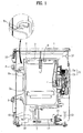
- FIG. 1 is a sectional view of a drum washing machine in accordance with one embodiment of the present invention.
- the drum washing machine of one embodiment comprises a cabinet 1, a tub 2, a drum 3, and a driving motor 5.
- the cabinet 1 forms the external housing of and defines the external appearance of the drum washing machine, and the tub 2 for containing washing water is installed in the cabinet 1 such that the tub 2 is supported by a damper 7 and a spring 6.
- the drum 3 is rotatably installed in the tub 2, and the rear surface of the drum 3 is connected to the driving motor 5.
- the driving motor 5 includes a rotor 5b and a stator 5a.
- a driving shaft 4 connected to the drum 3 for transmitting the rotary force of the rotor 5b directly to the drum 3, which is directly connected to the rotor 5b.
- a door 8 is provided on the front surface of the cabinet 1 at a position corresponding to an opening of the drum 3, and a gasket 9 for maintaining the hermetic sealing of the drum 3 is provided between the door 8 and the drum 3.
- a control panel 10 for receiving operating instructions from a user and controlling the overall operation of the washing machine is installed on the front surface of the washing machine above the door 8.
- a water supply valve 12 connected to a water supply (not shown) for supplying warm and cool water is installed on the rear surface of the cabinet 1.
- a drainage valve 14 connected to a drainage hose 13 for forcibly discharging the washing water from the tub 2 to the outside is installed on the lower part of the rear surface of the cabinet 1.
- the drum washing machine pumps and circulates the washing water stored in the tub 2 using a circulation pump, thereby improving washing and rinsing performance.
- the circulation pump 16 for circulating the washing water stored in the tub 2 is installed, for example, in the lower part of the cabinet 1.
- the circulation pump 16 pumps the washing water, and moves the washing water to the upper part of the tub 2.
- the pumped washing water is guided by circulation hoses 18 connected to the circulation pump 16, and one end of one circulation hose 18 is connected to the gasket 9 installed in front of the tub 2.
- the pumped washing water is supplied again to the inside of the tub 2, and more easily soaks the laundry. Further, since the washing water and the detergent are well mixed by the above circulation of the washing water, it is possible to improve the washing efficiency of the washing machine when the washing operation is performed by the driving of the drum 3.
- An inlet pipe 9a connected to one end of the circulation hose 18 is provided at one side of the gasket 9.
- the inlet pipe 9a is formed integrally with the gasket 9.
- the inlet pipe 9a may be installed independently of the gasket 9 as a separate component.
- the washing water stored in the tub 2 is pumped by the circulation pump 16 along the circulation hose 18 in washing and rinsing operations, and is introduced again to the inside of the drum 3, thereby improving the washing and rinsing performance.
- the drainage pump 14 is operated in a discharging operation when the operation of the circulation pump 16 is stopped, thereby discharging the washing water in the tub 2 to the outside through the drainage hose 13.
- the gasket 9 is made of rubber, the gasket 9 is severely vibrated in the washing and rinsing operations. Thereby, the washing water supplied through the inlet pipe 9a is not efficiently supplied to the inside of the drum 3, and flows downwardly along a glass 8a of the door 8. In this case, it is difficult for the circulated washing water to sufficiently impact the laundry.
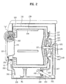
- FIG. 2 is a sectional view of the drum washing machine in accordance with another embodiment of the present invention
- FIG. 3 is a front view of the drum washing machine of FIG. 2.
- the drum washing machine comprises a cabinet 101, a tub 120, and a drum 130.
- the cabinet 101 forms the exterior housing and defines the external appearance of the drum washing machine, and an opening for placing laundry in the cabinet 101 is formed through the front surface of the cabinet 101.
- the tub 120 provided with an opening formed through the front surface thereof for containing washing water is installed in the cabinet 101.
- the tub 120 is supported by springs 152 and a damper 150 for damping vibration.
- the cylindrical drum 130 is rotatably provided in the tub 120.
- a plurality of lifters 134 for lifting and dropping the laundry when the drum 130 is rotated are formed on the inner cylindrical surface of the drum 130 such that the lifters 134 are separated from each other by a designated interval.
- the cabinet 101 has the shape of a rectangular parallelepiped, and a front panel 102 is installed on the front surface of the cabinet 101.
- An opening for placing the laundry in the tub 120 therethrough is formed through the front panel 102, and a door 110 is rotatably connected to one side of the opening.
- the front panel 102 may be formed integrally with the cabinet 101, or may be a separate component attached to the cabinet 101.
- a plurality of bosses 121 are formed on the front surface of the tub 120 in the circumferential direction, and bolts 105 are respectively inserted into the bosses 121, thereby fixing the front surface of the tub 120 to the front panel 102.
- the bolts 105 are fixedly inserted into the bosses 121 from the front of the front panel 102.
- a back spider-like structure 122 having a slightly smaller diameter than the outer diameter of the tub 120 is installed in the rear of the tub 120.
- a gasket 127 for preventing the leakage of the washing water is provided between the rear surface of the tub 120 and the back spider 122.
- a first bearing housing 124 and a second bearing housing 125 are assembled on the rear surface of the back spider 122.
- Bearings 126 for rotatably supporting a driving shaft 131 connected to the rear surface of the drum 130 are provided in the first and second bearing housings 124 and 125.
- a drum spider-like structure 132 to which the inner end of the driving shaft 131 is fixed, is fixed to the rear surface of the drum 130.
- a balance weight 133 for smoothing the rotation of the drum 130 is installed on the front surface of the drum 130.
- the driving shaft 131 of the drum 130 passes through the back spider 122 and the first and second bearing housings 124 and 125, and the outer end of the driving shaft 131 is connected to a driving motor 140.
- the driving motor 140 includes a stator 141 fixed to the rear surface of the second bearing housing 125, and a rotor 142 connected to the driving shaft 131.
- a rotating magnetic field is formed between the rotor 142 and the stator 141, and the rotor 142 is rotated along the outer cylindrical surface of the stator 141.
- Two suspension springs 152 for supporting the rear part of the tub 120 are installed at both sides of the extended lower part of the first bearing housing 124 connected to the back spider 122.
- the extended lower part of the first bearing housing 124 is forwardly bent to have an approximately 'L' shape, and an 'L'-shaped bracket 128 is connected to the extended lower part of the first bearing housing 124.
- the damper 150 for absorbing the vibration of the drum 130 is connected to the front part of the bracket 128.
- the damper 150 is inclined and supported to the rear surface of the cabinet 101, thereby efficiently absorbing both longitudinal and lateral vibrations of the bearing housings 124 and 125.
- the length of the bracket 128 may be modified so that the suspension springs 152 and the damper 150 are installed at positions corresponding to the center of gravity of an assembled structure of the drum 130, the tub 120, and the driving motor 140 including the bearing housings 124 and 125.
- a drainage pump 165 is installed in the lower portion of the rear part of the cabinet 101.
- the drainage pump 165 pumps and discharges the washing water contained in the tub 120 to the outside through first and second drainage hoses 166 and 167 made of elastic material after the washing of the laundry is completed.
- a circulation pump 160 for pumping the washing water, supplied to the tub 120, to the outside of the tub 120 and re-supplying the washing water to the inside of the tub 120 is installed in the lower portion of the cabinet 101.
- An inlet of the circulation pump 160 is connected to a first circulation hose 161, which is made of elastic material and connected to the lower part of the tub 120, and an outlet of the circulation pump 160 is connected to a second circulation hose 162, which is made of elastic material and connected to the upper part of the tub 120.
- FIG. 4 is an enlarged view of the portion "A" of FIG. 2, i.e., an enlarged sectional view of the connection portion of the second circulation hose 162 of the present invention.
- an inlet pipe 171 protrudes or extends from the front surface of the tub 120, and one end of the second circulation hose 162 is connected to the inlet pipe 171.
- the inlet pipe 171 is installed at a position spaced from the zenith (or foremost point) of the front surface of the tub 120 by an angle of approximately 30 degrees.
- a guide 172 is provided just under the inlet pipe 171, and serves to guide the washing water introduced through the inlet pipe 171 to the inside of the drum 130. Accordingly, preferably, the guide 172 is downwardly inclined towards the opening of the drum 130. Further, preferably, a spray nozzle for spraying the circulated washing water is installed at one side of the inlet pipe 171.
- the inlet pipe 171 and the guide 172 may be formed integrally with the front surface of the tub 120, or may be formed independently of the front surface of the tub 120. In the case that the inlet pipe 171 and the guide 172 are formed independently of the front surface of the tub 120, preferably, the inlet pipe 171 and the guide 172 are fixed to the front surface of the tub 120 using an adhesive agent or screws.
- washing water is supplied to the inside of the tub 120 through the water supply device (not shown) provided in the cabinet 101.
- the washing water is mixed with detergent and is then supplied to the inside of the tub 120.
- the washing water pumped by the circulation pump 160 through the second circulation hose 162 is introduced to the inside of the tub 120 through the inlet pipe 171.
- the washing water is guided to the inside of the drum 130 by the guide 172, and is sprayed onto the laundry in the drum 130.
- the sprayed washing water collides with the laundry, and sufficiently soaks the laundry under the condition that the washing water is mixed with the detergent.
- the drainage pump 165 while the operation of the circulation pump 160 is stopped, thereby discharging the washing water contained in the tub 120 to the outside through the first and second drainage hoses 166 and 167.
- the drum washing machine of the present invention has several effects, as follows:
- the washing water since the washing water, circulated through the front surface of the tub, is smoothly supplied to the inside of the drum, the washing water sufficiently soaks the laundry in the drum. Thereby, it is possible to improve washing and rinsing performances of the drum washing machine.
Abstract
Description
- The present invention relates to a drum washing machine, and more particularly, to a drum washing machine having a device for circulating washing water supplied to the inside of a drum.
- Generally, a drum washing machine is an apparatus for performing the washing of laundry by rotating a drum under the condition that detergent, washing water, and laundry are placed in the drum. Here, the washing of the laundry is performed by means of friction between the laundry and the washing water and emulsification of the detergent, and simultaneously the laundry is repeatedly lifted and dropped by the rotation of the drum.
- Accordingly, the drum washing machine minimizes damage to the laundry and entanglement of the laundry, and has laundry-beating and rubbing effects.
- In an initial stage of the operation of the washing machine, the washing water is supplied to the inside of a tub, and soaks the laundry contained in the drum. Preferably, the drum is rotated to perform the washing of the laundry after the laundry is sufficiently soaked by the washing water.
- However, the above conventional drum washing machine requires a long time to soak the laundry by means of the supplied washing water, thereby increasing the overall washing time.
- Further, the conventional drum washing machine performs the washing of the laundry under the condition that the detergent and the washing water are not completely mixed, thus deteriorating the washing efficiency.
- Accordingly, the present invention is directed to a drum washing machine that substantially obviates one or more problems due to limitations and disadvantages of the
- An object of the present invention is to provide a drum washing machine having an improved structure so that washing water circulated by a circulation device is efficiently supplied to the inside of a drum.
- Additional advantages, objects, and features of the invention will be set forth in part in the description which follows and in part will become apparent to those having ordinary skill in the art upon examination of the following or may be learned from practice of the invention. The objectives and other advantages of the invention may be realized and attained by the structure particularly pointed out in the written description and claims hereof as well as the appended drawings.
- To achieve these objects and other advantages and in accordance with the purpose of the invention, as embodied and broadly described herein, a drum washing machine includes a cabinet forming the external housing of the washing machine; a tub installed in the cabinet for containing washing water; a drum rotatably installed in the tub; a circulation pump for pumping the washing water in the tub and re-supplying the washing water to the inside of the drum; and circulation hoses forming a circulation path between the circulation pump and the tub.
- Preferably, the front surface of the tub may be connected to the front surface of the cabinet. An inlet pipe, connected to one circulation hose, for guiding the washing water guided by the circulation hose to the inside of the drum, may be installed on the front surface of the tub. Preferably, the inlet pipe may protrude from the front surface of the tub. The inlet pipe may be formed integrally with the tub. Alternately, the inlet pipe may be formed independently of the tub, and fixed to the front surface of the tub by a fixing mechanism.
- The inlet pipe may be installed at a position separated from the upper end of the tub by a designated angle.
- Further, preferably, the drum washing machine may also include a guide for guiding the washing water, discharged through the inlet pipe, to the inside of the drum. The guide may be extended to be downwardly inclined towards the inside of the drum. The guide may be formed integrally with the tub. Alternately, the guide may be formed independently of the tub, and fixed to the front end of the tub by a fixing mechanism.
- Preferably, a bearing housing may be fixed to the rear surface of the tub, and the lower part of the bearing housing may be extended and supported by suspension springs and a damper. Here, the extended lower part of the bearing housing may be forwardly bent to have an approximately 'L' shape. A bracket for reinforcing the strength of the bearing housing may be connected to the extended lower part of the bearing housing.
- In another aspect of the present invention, a drum washing machine includes a cabinet forming the external housing of the washing machine; a tub, installed in the cabinet for containing washing water, the front surface of which is connected to the front surface of the cabinet; a drum rotatably installed in the tub; a circulation pump for pumping the washing water in the tub and re-supplying the washing water to the inside of the drum; and circulation hoses, for forming a circulation path between the circulation pump and the tub, one end of which is connected to the front surface of the tub.
- In yet another aspect of the present invention, a drum washing machine includes a cabinet forming the external housing of the washing machine; a tub, installed in the cabinet for containing washing water, the front surface of which is connected to the front surface of the cabinet; a drum rotatably installed in the tub; a circulation pump for pumping the washing water in the tub and re-supplying the washing water to the inside of the drum; circulation hoses forming a circulation path between the circulation pump and the tub; and a guide extended to be downwardly inclined towards the inside of the drum for guiding the washing water discharged through the circulation hoses.
- It is to be understood that both the foregoing general description and the following detailed description of the present invention are exemplary and explanatory and are intended to provide further explanation of the invention as claimed.
- The accompanying drawings, which are included to provide a further understanding of the invention and are incorporated in and constitute a part of this application, illustrate embodiments of the invention and together with the description serve to explain the principle of the invention.
- The above and other objects, features and advantages of the present invention will be made apparent from the following description of the preferred embodiments, given as non-limiting examples, with reference to the accompanying drawings in which:
- FIG. 1 is a sectional view of a drum washing machine in accordance with one embodiment of the present invention;
- FIG. 2 is a sectional view of a drum washing machine in accordance with another embodiment of the present invention;
- FIG. 3 is a front view of the drum washing machine of FIG. 2; and
- FIG. 4 is an enlarged view of the portion "A" of FIG. 2.
- The present invention is further described in the detailed description which follows, by reference to the noted plurality of drawings by way of non-limiting examples of preferred embodiments of the present invention, in which like reference numerals represent similar parts throughout the several views of the drawings, and wherein:
- Hereinafter, drum washing machines in accordance with the preferred embodiments of the present invention will be described in detail with reference to the accompanying drawings.
- FIG. 1 is a sectional view of a drum washing machine in accordance with one embodiment of the present invention.
- As shown in FIG. 1, the drum washing machine of one embodiment comprises a
cabinet 1, atub 2, adrum 3, and adriving motor 5. - The
cabinet 1 forms the external housing of and defines the external appearance of the drum washing machine, and thetub 2 for containing washing water is installed in thecabinet 1 such that thetub 2 is supported by adamper 7 and aspring 6. Thedrum 3 is rotatably installed in thetub 2, and the rear surface of thedrum 3 is connected to thedriving motor 5. - The
driving motor 5 includes arotor 5b and astator 5a. Adriving shaft 4 connected to thedrum 3 for transmitting the rotary force of therotor 5b directly to thedrum 3, which is directly connected to therotor 5b. - A
door 8 is provided on the front surface of thecabinet 1 at a position corresponding to an opening of thedrum 3, and agasket 9 for maintaining the hermetic sealing of thedrum 3 is provided between thedoor 8 and thedrum 3. Acontrol panel 10 for receiving operating instructions from a user and controlling the overall operation of the washing machine is installed on the front surface of the washing machine above thedoor 8. - A
water supply valve 12 connected to a water supply (not shown) for supplying warm and cool water is installed on the rear surface of thecabinet 1. Adrainage valve 14 connected to adrainage hose 13 for forcibly discharging the washing water from thetub 2 to the outside is installed on the lower part of the rear surface of thecabinet 1. - The drum washing machine pumps and circulates the washing water stored in the
tub 2 using a circulation pump, thereby improving washing and rinsing performance. For this reason, thecirculation pump 16 for circulating the washing water stored in thetub 2 is installed, for example, in the lower part of thecabinet 1. The circulation pump 16 pumps the washing water, and moves the washing water to the upper part of thetub 2. Then, the pumped washing water is guided bycirculation hoses 18 connected to thecirculation pump 16, and one end of onecirculation hose 18 is connected to thegasket 9 installed in front of thetub 2. - Thereby, the pumped washing water is supplied again to the inside of the
tub 2, and more easily soaks the laundry. Further, since the washing water and the detergent are well mixed by the above circulation of the washing water, it is possible to improve the washing efficiency of the washing machine when the washing operation is performed by the driving of thedrum 3. - An
inlet pipe 9a connected to one end of thecirculation hose 18 is provided at one side of thegasket 9. Preferably, theinlet pipe 9a is formed integrally with thegasket 9. However, theinlet pipe 9a may be installed independently of thegasket 9 as a separate component. - Through the above configuration, the washing water stored in the
tub 2 is pumped by thecirculation pump 16 along thecirculation hose 18 in washing and rinsing operations, and is introduced again to the inside of thedrum 3, thereby improving the washing and rinsing performance. Thereafter, thedrainage pump 14 is operated in a discharging operation when the operation of thecirculation pump 16 is stopped, thereby discharging the washing water in thetub 2 to the outside through thedrainage hose 13. - Since the
gasket 9 is made of rubber, thegasket 9 is severely vibrated in the washing and rinsing operations. Thereby, the washing water supplied through theinlet pipe 9a is not efficiently supplied to the inside of thedrum 3, and flows downwardly along aglass 8a of thedoor 8. In this case, it is difficult for the circulated washing water to sufficiently impact the laundry. - Accordingly, in order to solve the above problem, a drum washing machine in accordance with another embodiment of the present invention will be described, as follows.
- FIG. 2 is a sectional view of the drum washing machine in accordance with another embodiment of the present invention, and FIG. 3 is a front view of the drum washing machine of FIG. 2.
- As shown in FIGs. 2 and 3, the drum washing machine comprises a
cabinet 101, atub 120, and adrum 130. Thecabinet 101 forms the exterior housing and defines the external appearance of the drum washing machine, and an opening for placing laundry in thecabinet 101 is formed through the front surface of thecabinet 101. - The
tub 120 provided with an opening formed through the front surface thereof for containing washing water is installed in thecabinet 101. Thetub 120 is supported bysprings 152 and adamper 150 for damping vibration. - The
cylindrical drum 130, the front surface of which is openable, is rotatably provided in thetub 120. Preferably, a plurality oflifters 134 for lifting and dropping the laundry when thedrum 130 is rotated are formed on the inner cylindrical surface of thedrum 130 such that thelifters 134 are separated from each other by a designated interval. - The
cabinet 101 has the shape of a rectangular parallelepiped, and afront panel 102 is installed on the front surface of thecabinet 101. An opening for placing the laundry in thetub 120 therethrough is formed through thefront panel 102, and adoor 110 is rotatably connected to one side of the opening. Here, thefront panel 102 may be formed integrally with thecabinet 101, or may be a separate component attached to thecabinet 101. - A plurality of
bosses 121 are formed on the front surface of thetub 120 in the circumferential direction, andbolts 105 are respectively inserted into thebosses 121, thereby fixing the front surface of thetub 120 to thefront panel 102. Preferably, thebolts 105 are fixedly inserted into thebosses 121 from the front of thefront panel 102. - A back spider-
like structure 122 having a slightly smaller diameter than the outer diameter of thetub 120 is installed in the rear of thetub 120. Agasket 127 for preventing the leakage of the washing water is provided between the rear surface of thetub 120 and theback spider 122. Afirst bearing housing 124 and asecond bearing housing 125 are assembled on the rear surface of theback spider 122.Bearings 126 for rotatably supporting a drivingshaft 131 connected to the rear surface of thedrum 130 are provided in the first andsecond bearing housings - A drum spider-
like structure 132, to which the inner end of the drivingshaft 131 is fixed, is fixed to the rear surface of thedrum 130. Abalance weight 133 for smoothing the rotation of thedrum 130 is installed on the front surface of thedrum 130. The drivingshaft 131 of thedrum 130 passes through theback spider 122 and the first andsecond bearing housings shaft 131 is connected to a driving motor 140. - The driving motor 140 includes a stator 141 fixed to the rear surface of the
second bearing housing 125, and arotor 142 connected to the drivingshaft 131. When power is supplied to the stator 141, a rotating magnetic field is formed between therotor 142 and the stator 141, and therotor 142 is rotated along the outer cylindrical surface of the stator 141. - Two suspension springs 152 for supporting the rear part of the
tub 120 are installed at both sides of the extended lower part of thefirst bearing housing 124 connected to theback spider 122. The extended lower part of thefirst bearing housing 124 is forwardly bent to have an approximately 'L' shape, and an 'L'-shapedbracket 128 is connected to the extended lower part of thefirst bearing housing 124. - The
damper 150 for absorbing the vibration of thedrum 130 is connected to the front part of thebracket 128. Thedamper 150 is inclined and supported to the rear surface of thecabinet 101, thereby efficiently absorbing both longitudinal and lateral vibrations of the bearinghousings - The length of the
bracket 128 may be modified so that the suspension springs 152 and thedamper 150 are installed at positions corresponding to the center of gravity of an assembled structure of thedrum 130, thetub 120, and the driving motor 140 including the bearinghousings - A
drainage pump 165 is installed in the lower portion of the rear part of thecabinet 101. Thedrainage pump 165 pumps and discharges the washing water contained in thetub 120 to the outside through first andsecond drainage hoses - A
circulation pump 160 for pumping the washing water, supplied to thetub 120, to the outside of thetub 120 and re-supplying the washing water to the inside of thetub 120 is installed in the lower portion of thecabinet 101. An inlet of thecirculation pump 160 is connected to afirst circulation hose 161, which is made of elastic material and connected to the lower part of thetub 120, and an outlet of thecirculation pump 160 is connected to asecond circulation hose 162, which is made of elastic material and connected to the upper part of thetub 120. - FIG. 4 is an enlarged view of the portion "A" of FIG. 2, i.e., an enlarged sectional view of the connection portion of the
second circulation hose 162 of the present invention. - As shown in FIG. 4, an
inlet pipe 171 protrudes or extends from the front surface of thetub 120, and one end of thesecond circulation hose 162 is connected to theinlet pipe 171. Preferably, theinlet pipe 171 is installed at a position spaced from the zenith (or foremost point) of the front surface of thetub 120 by an angle of approximately 30 degrees. - A
guide 172 is provided just under theinlet pipe 171, and serves to guide the washing water introduced through theinlet pipe 171 to the inside of thedrum 130. Accordingly, preferably, theguide 172 is downwardly inclined towards the opening of thedrum 130. Further, preferably, a spray nozzle for spraying the circulated washing water is installed at one side of theinlet pipe 171. - The
inlet pipe 171 and theguide 172 may be formed integrally with the front surface of thetub 120, or may be formed independently of the front surface of thetub 120. In the case that theinlet pipe 171 and theguide 172 are formed independently of the front surface of thetub 120, preferably, theinlet pipe 171 and theguide 172 are fixed to the front surface of thetub 120 using an adhesive agent or screws. - Hereinafter, the operation of the above drum washing machine of the present invention will be described.
- When a user places laundry in the
drum 130 and applies power to the drum washing machine to drive the washing machine, washing water is supplied to the inside of thetub 120 through the water supply device (not shown) provided in thecabinet 101. Preferably, the washing water is mixed with detergent and is then supplied to the inside of thetub 120. - When the supply of the washing water is completed, a signal is applied to the driving motor 140. Then, the
rotor 142 is rotated along the outer cylindrical surface of the stator 141, and thus thedrum 130 connected to therotor 142 is rotated so that the laundry in thedrum 130 is washed. Here, since thecirculation pump 160 is periodically operated, a part of the washing water in thetub 120 is circulated through thefirst circulation hose 161 and thesecond circulation hose 162. - The washing water pumped by the
circulation pump 160 through thesecond circulation hose 162 is introduced to the inside of thetub 120 through theinlet pipe 171. The washing water is guided to the inside of thedrum 130 by theguide 172, and is sprayed onto the laundry in thedrum 130. Here, the sprayed washing water collides with the laundry, and sufficiently soaks the laundry under the condition that the washing water is mixed with the detergent. - In the case that the washing water is discharged to the outside during or after the washing and rinsing operations, the
drainage pump 165 while the operation of thecirculation pump 160 is stopped, thereby discharging the washing water contained in thetub 120 to the outside through the first andsecond drainage hoses - As described above, the drum washing machine of the present invention has several effects, as follows:
- Since the front surface of the tub is directly connected to the cabinet of the drum washing machine, the circulation hose connected to the circulation pump is stably fixed to the inlet pipe provided on the front surface of the tub. Thereby, it is possible to prevent the washing water, re-supplied to the inside of the tub through the circulation pump, from flowing down along the door.
- Further, since the washing water, circulated through the front surface of the tub, is smoothly supplied to the inside of the drum, the washing water sufficiently soaks the laundry in the drum. Thereby, it is possible to improve washing and rinsing performances of the drum washing machine.
- It will be apparent to those skilled in the art that various modifications and variations can be made in the present invention without departing from the spirit or scope of the inventions. Thus, it is intended that the present invention covers the modifications and variations of this invention provided they come within the scope of the appended claims and their equivalents.
- Although the invention has been described with reference to an exemplary embodiment, it is understood that the words that have been used are words of description and illustration, rather than words of limitation. Changes may be made, within the purview of the appended claims, as presently stated and as amended, without departing from the scope and spirit of the present invention in its aspects. Although the invention has been described herein with reference to particular means, materials and embodiments, the invention is not intended to be limited to the particulars disclosed herein. Instead, the invention extends to all functionally equivalent structures, methods and uses, such as are within the scope of the appended claims.
- The particulars shown herein are by way of example and for purposes of illustrative discussion of the embodiments of the present invention only and are presented in the cause of providing what is believed to be the most useful and readily understood description of the principles and conceptual aspects of the present invention. In this regard, no attempt is made to show structural details of the present invention in more detail than is necessary for the fundamental understanding of the present invention, the description is taken with the drawings making apparent to those skilled in the art how the forms of the present invention may be embodied in practice.
Claims (16)
- A drum washing machine comprising:a cabinet forming an external housing of the washing machine;a tub installed in the cabinet for containing washing water;a drum rotatably installed in the tub;a circulation pump that pumps the washing water in the tub and resupplies the washing water to the inside of the drum; andat least one circulation hose providing a circulation path between the circulation pump and the tub.
- The drum washing machine as set forth in claim 1, wherein a front surface of the tub is connected to a front surface of the cabinet.
- The drum washing machine as set forth in claim 2, wherein an inlet pipe, connected to a circulation hose that guides the washing water conveyed by the circulation hose to the inside of the drum, is installed on the front surface of the tub.
- The drum washing machine as set forth in claim 3, wherein the inlet pipe protrudes from the front surface of the tub.
- The drum washing machine as set forth in claim 3, wherein the inlet pipe is integral with the tub.
- The drum washing machine as set forth in claim 3, wherein the inlet pipe is distinct from the tub, and is secured to the front surface of the tub by a fixing device.
- The drum washing machine as set forth in claim 3, wherein the inlet pipe is located at a position spaced from the upper end of the tub by a predetermined angle.
- The drum washing machine as set forth in claim 3, further comprising a guide for guiding the washing water, discharged through the inlet pipe, to the inside of the drum.
- The drum washing machine as set forth in claim 8, wherein the guide is configured to incline downwardly towards the inside of the drum.
- The drum washing machine as set forth in claim 8, wherein the guide is integral with the tub.
- The drum washing machine as set forth in claim 8, wherein the guide is distinct from the tub, and secured to the front end of the tub by a fixing device.
- The drum washing machine as set forth in claim 1, wherein a bearing housing is fixed to the rear surface of the tub, and the lower part of the bearing housing extends from the rear surface and is supported by a suspension spring and a damper.
- The drum washing machine as set forth in claim 12, wherein the lower part of the bearing housing is configured to have an approximately "L" shape, with a portion of the "L" shape of the lower part of the bearing housing extending forwardly.
- The drum washing machine as set forth in claim 13, wherein a bracket for reinforcing the bearing housing is connected to the lower part of the bearing housing.
- A drum washing machine comprising:a cabinet forming an external housing of the washing machine;a tub, installed in the cabinet for containing washing water, a front surface of is the tub being connected to a front surface of the cabinet;a drum rotatably installed in the tub;a circulation pump that pumps the washing water in the tub and resupplies the washing water to the inside of the drum; andat least one circulation hose, providing a circulation path between the circulation pump and the tub, one end of is the circulation hose being connected to the front surface of the tub.
- A drum washing machine comprising:a cabinet forming an external housing of the washing machine;a tub, installed in the cabinet for containing washing water, the front surface of is the tub being connected to a front surface of the cabinet;a drum rotatably installed in the tub;a circulation pump that pumps the washing water in the tub and resupplies the washing water to the inside of the drum;at least one circulation hose providing a circulation path between the circulation pump and the tub; anda guide configured to incline downwardly towards the inside of the drum guides the washing water discharged through the circulation hose to the drum.
Priority Applications (1)
| Application Number | Priority Date | Filing Date | Title |
|---|---|---|---|
| EP10012893.3A EP2298980A3 (en) | 2005-01-10 | 2005-07-21 | Drum washing machine |
Applications Claiming Priority (1)
| Application Number | Priority Date | Filing Date | Title |
|---|---|---|---|
| KR1020050002136A KR100765277B1 (en) | 2005-01-10 | 2005-01-10 | drum type washer |
Related Child Applications (1)
| Application Number | Title | Priority Date | Filing Date |
|---|---|---|---|
| EP10012893.3A Division EP2298980A3 (en) | 2005-01-10 | 2005-07-21 | Drum washing machine |
Publications (2)
| Publication Number | Publication Date |
|---|---|
| EP1679401A2 true EP1679401A2 (en) | 2006-07-12 |
| EP1679401A3 EP1679401A3 (en) | 2006-09-06 |
Family
ID=36177264
Family Applications (2)
| Application Number | Title | Priority Date | Filing Date |
|---|---|---|---|
| EP05015884A Withdrawn EP1679401A3 (en) | 2005-01-10 | 2005-07-21 | Drum washing machine |
| EP10012893.3A Withdrawn EP2298980A3 (en) | 2005-01-10 | 2005-07-21 | Drum washing machine |
Family Applications After (1)
| Application Number | Title | Priority Date | Filing Date |
|---|---|---|---|
| EP10012893.3A Withdrawn EP2298980A3 (en) | 2005-01-10 | 2005-07-21 | Drum washing machine |
Country Status (5)
| Country | Link |
|---|---|
| US (1) | US7574879B2 (en) |
| EP (2) | EP1679401A3 (en) |
| JP (2) | JP2006192249A (en) |
| KR (1) | KR100765277B1 (en) |
| CN (1) | CN1804190B (en) |
Cited By (5)
| Publication number | Priority date | Publication date | Assignee | Title |
|---|---|---|---|---|
| CN101831777A (en) * | 2009-03-09 | 2010-09-15 | 松下电器产业株式会社 | Tumbling-box washing machine |
| WO2011015457A1 (en) * | 2009-08-04 | 2011-02-10 | BSH Bosch und Siemens Hausgeräte GmbH | Device for generating foam in a laundry treatment machine, method for using same and laundry treatment machine |
| EP2471993A1 (en) * | 2009-08-24 | 2012-07-04 | Kabushiki Kaisha Toshiba | Drum type washing machine |
| ES2463315R1 (en) * | 2012-11-27 | 2014-07-23 | BSH Electrodomésticos España S.A. | Domestic appliance, especially laundry washing or drying machine |
| WO2016050591A1 (en) * | 2014-10-02 | 2016-04-07 | BSH Hausgeräte GmbH | Laundry care appliance having a deflection element |
Families Citing this family (31)
| Publication number | Priority date | Publication date | Assignee | Title |
|---|---|---|---|---|
| KR100464054B1 (en) | 2002-12-27 | 2005-01-03 | 엘지전자 주식회사 | Drum type washing machine with united cabinet/tub |
| EP1433891B1 (en) | 2002-12-27 | 2012-05-02 | LG Electronics Inc. | Drum type washing machine |
| KR100634802B1 (en) | 2004-07-20 | 2006-10-16 | 엘지전자 주식회사 | Drum washing machine |
| KR100686017B1 (en) * | 2005-05-11 | 2007-02-26 | 엘지전자 주식회사 | Washing machine |
| US7841220B2 (en) | 2005-09-30 | 2010-11-30 | Lg Electronics Inc. | Drum-type washing machine |
| US7536882B2 (en) | 2006-03-29 | 2009-05-26 | Lg Electronics Inc. | Drum type washing machine |
| KR101362783B1 (en) * | 2007-02-27 | 2014-02-12 | 엘지전자 주식회사 | Washing machine |
| KR101302125B1 (en) * | 2007-03-20 | 2013-08-30 | 엘지전자 주식회사 | Washing Machine |
| KR100826206B1 (en) | 2007-03-21 | 2008-04-30 | 엘지전자 주식회사 | drum type washer |
| KR101315425B1 (en) * | 2007-03-31 | 2013-10-07 | 엘지전자 주식회사 | Washing machine |
| KR20100045316A (en) * | 2008-10-23 | 2010-05-03 | 엘지전자 주식회사 | Washing machine |
| KR101700189B1 (en) * | 2008-12-30 | 2017-01-26 | 엘지전자 주식회사 | Laundry machine |
| KR101635870B1 (en) * | 2009-01-07 | 2016-07-04 | 엘지전자 주식회사 | Washing machine |
| JP5320113B2 (en) * | 2009-03-11 | 2013-10-23 | ハイアール グループ コーポレーション | Washing machine |
| KR101698854B1 (en) * | 2009-05-28 | 2017-01-24 | 엘지전자 주식회사 | manufacturing method for washing machine |
| JP5299174B2 (en) * | 2009-08-27 | 2013-09-25 | パナソニック株式会社 | Drum washing machine |
| JP5397093B2 (en) * | 2009-08-27 | 2014-01-22 | パナソニック株式会社 | Drum washing machine |
| JP5397092B2 (en) * | 2009-08-27 | 2014-01-22 | パナソニック株式会社 | Drum washing machine |
| CN102482834B (en) * | 2009-08-27 | 2014-12-17 | 松下电器产业株式会社 | Drum type washing machine |
| KR101756676B1 (en) * | 2010-04-28 | 2017-07-11 | 삼성전자주식회사 | Hose guide member and washing machine having the same |
| WO2014030332A1 (en) * | 2012-08-24 | 2014-02-27 | パナソニック株式会社 | Washing and drying machine |
| DE202015101403U1 (en) | 2015-03-19 | 2015-03-26 | Antonio Chiriatti | Machine for washing clothes or drying clothes |
| DE102015216363A1 (en) * | 2015-08-27 | 2017-03-02 | BSH Hausgeräte GmbH | Washing machine with door area to prevent laundry damage |
| JP6543808B2 (en) * | 2015-10-16 | 2019-07-17 | パナソニックIpマネジメント株式会社 | Washing machine |
| WO2019201118A1 (en) * | 2018-04-16 | 2019-10-24 | 青岛海尔滚筒洗衣机有限公司 | Front-loading washer and spray system thereof |
| CN110387698A (en) * | 2018-04-16 | 2019-10-29 | 青岛海尔滚筒洗衣机有限公司 | Roller washing machine and its spray system |
| CN110387699B (en) * | 2018-04-16 | 2021-10-29 | 青岛海尔洗涤电器有限公司 | Roller washing machine and spraying system thereof |
| WO2019235012A1 (en) * | 2018-06-06 | 2019-12-12 | シャープ株式会社 | Washing machine |
| KR102638188B1 (en) * | 2019-02-01 | 2024-02-16 | 엘지전자 주식회사 | Washing machine with a conduit for supplying water to nozzles at gasket and manufacturing method of the conduit |
| KR20220063349A (en) | 2020-11-10 | 2022-05-17 | 이경술 | Structure for cleaning brush of drum out side a drum type washer |
| US11859334B2 (en) | 2020-12-09 | 2024-01-02 | Samsung Electronics Co., Ltd. | Washing machine |
Citations (1)
| Publication number | Priority date | Publication date | Assignee | Title |
|---|---|---|---|---|
| EP0247421A2 (en) * | 1981-11-10 | 1987-12-02 | The Procter & Gamble Company | Detergent compositions and washing liquors for use in textile laundering processes |
Family Cites Families (33)
| Publication number | Priority date | Publication date | Assignee | Title |
|---|---|---|---|---|
| US2565604A (en) * | 1948-06-28 | 1951-08-28 | John J Geiger | Washing machine |
| US2930217A (en) * | 1957-01-07 | 1960-03-29 | William F Rehmke | Washing machine |
| US3089326A (en) * | 1960-06-08 | 1963-05-14 | Frame Sa | Washing machine |
| US3206267A (en) * | 1963-08-12 | 1965-09-14 | Ametek Inc | Laundry machines |
| US3459461A (en) * | 1967-10-02 | 1969-08-05 | Thomas W Bannon Jr | Washer-extractor unitary frame structure with parallel plates |
| US3531954A (en) * | 1968-08-06 | 1970-10-06 | Michael R Krupsky | Combination clothes washer and dryer |
| FR2401888A1 (en) * | 1977-09-06 | 1979-03-30 | Europ Propulsion | Impregnating porous carbon body with refractory material - esp. carbide, boride and/or nitride to improve compressive strength and erosion resistance |
| DD155854A3 (en) * | 1980-05-09 | 1982-07-14 | Keller Karl Heinz | FORMATION OF SAFETY AND SEAL ASSEMBLY FOR WASHING MACHINE DRIVESHAFTS |
| DE3275393D1 (en) * | 1981-12-18 | 1987-03-12 | Cerac Inst Sa | Washing machine |
| DE3811583A1 (en) * | 1988-04-07 | 1989-10-19 | Licentia Gmbh | Rotary washing machine which can be front-loaded |
| DE3934434A1 (en) * | 1989-10-14 | 1991-04-18 | Licentia Gmbh | Washing machine with conical water-tight drum - in which double-walled drum consists of cylindrical perforated inner wall and conical outer jacket |
| JPH0492697A (en) * | 1990-08-09 | 1992-03-25 | Okayama Pref Gov | Rotary drum type washing machine |
| DE4310594A1 (en) * | 1993-03-31 | 1994-10-06 | Bosch Siemens Hausgeraete | Washing machine with a casing-loadable laundry drum mounted horizontally within a tub |
| DE4330079C2 (en) * | 1993-09-06 | 2000-05-11 | Bsh Bosch Siemens Hausgeraete | Front loading drum washing machine |
| MY115384A (en) * | 1994-12-06 | 2003-05-31 | Sharp Kk | Drum type washing machine and drier |
| KR960034538A (en) * | 1995-03-13 | 1996-10-24 | 구자홍 | Drum Washing Machine |
| JPH08299658A (en) * | 1995-05-12 | 1996-11-19 | Toshiba Corp | Drum type washing machine |
| US5887456A (en) * | 1995-08-30 | 1999-03-30 | Sharp Kabushiki Kaisha | Drum type drying/washing machine |
| DE69608876T3 (en) * | 1995-12-28 | 2006-05-24 | Samsung Electronics Co., Ltd., Suwon | Drum machine with balancing devices |
| KR100329476B1 (en) | 1998-09-14 | 2002-06-20 | 윤종용 | Washing water circulator of drum washing machine |
| CN2372345Y (en) * | 1999-05-12 | 2000-04-05 | 海尔集团公司 | Spray device of drum washing machine |
| KR100436144B1 (en) * | 2001-09-28 | 2004-06-14 | 삼성전자주식회사 | Drum type washing machine |
| JP2004057821A (en) * | 2002-07-30 | 2004-02-26 | Lg Electron Inc | Washing machine |
| KR100484808B1 (en) * | 2002-07-30 | 2005-04-22 | 엘지전자 주식회사 | A circulating apparatus of washer |
| KR100484807B1 (en) * | 2002-07-30 | 2005-04-22 | 엘지전자 주식회사 | A shower connector of washer |
| KR100464054B1 (en) * | 2002-12-27 | 2005-01-03 | 엘지전자 주식회사 | Drum type washing machine with united cabinet/tub |
| US7584633B2 (en) * | 2003-04-14 | 2009-09-08 | Lg Electronics Inc. | Spray type drum washing machine |
| KR100517616B1 (en) * | 2003-04-19 | 2005-09-28 | 엘지전자 주식회사 | Drum washing machine |
| KR100517619B1 (en) * | 2003-04-25 | 2005-09-28 | 엘지전자 주식회사 | Circulation apparatus of drum washer |
| DE102004026735B4 (en) * | 2003-06-09 | 2009-11-19 | Lg Electronics Inc. | Drum-type mono trough washing machine and method of controlling the same |
| KR100688160B1 (en) * | 2003-08-07 | 2007-03-02 | 엘지전자 주식회사 | Front loading type drum washing machine |
| KR100634802B1 (en) * | 2004-07-20 | 2006-10-16 | 엘지전자 주식회사 | Drum washing machine |
| KR100743707B1 (en) * | 2005-02-03 | 2007-07-30 | 엘지전자 주식회사 | Drum washer having a tub coupled to cabinet and a drying device |
-
2005
- 2005-01-10 KR KR1020050002136A patent/KR100765277B1/en active IP Right Grant
- 2005-06-24 JP JP2005185304A patent/JP2006192249A/en not_active Withdrawn
- 2005-07-21 EP EP05015884A patent/EP1679401A3/en not_active Withdrawn
- 2005-07-21 EP EP10012893.3A patent/EP2298980A3/en not_active Withdrawn
- 2005-07-25 US US11/187,927 patent/US7574879B2/en active Active
- 2005-08-09 CN CN2005100897963A patent/CN1804190B/en active Active
-
2011
- 2011-08-05 JP JP2011172324A patent/JP2011212506A/en active Pending
Patent Citations (1)
| Publication number | Priority date | Publication date | Assignee | Title |
|---|---|---|---|---|
| EP0247421A2 (en) * | 1981-11-10 | 1987-12-02 | The Procter & Gamble Company | Detergent compositions and washing liquors for use in textile laundering processes |
Cited By (8)
| Publication number | Priority date | Publication date | Assignee | Title |
|---|---|---|---|---|
| CN101831777A (en) * | 2009-03-09 | 2010-09-15 | 松下电器产业株式会社 | Tumbling-box washing machine |
| CN101831777B (en) * | 2009-03-09 | 2012-07-04 | 松下电器产业株式会社 | Drum-type washer |
| WO2011015457A1 (en) * | 2009-08-04 | 2011-02-10 | BSH Bosch und Siemens Hausgeräte GmbH | Device for generating foam in a laundry treatment machine, method for using same and laundry treatment machine |
| EA019632B1 (en) * | 2009-08-04 | 2014-05-30 | Бсх Бош Унд Сименс Хаусгерете Гмбх | Laundry treatment machine using foam |
| EP2471993A1 (en) * | 2009-08-24 | 2012-07-04 | Kabushiki Kaisha Toshiba | Drum type washing machine |
| EP2471993A4 (en) * | 2009-08-24 | 2013-03-13 | Toshiba Kk | Drum type washing machine |
| ES2463315R1 (en) * | 2012-11-27 | 2014-07-23 | BSH Electrodomésticos España S.A. | Domestic appliance, especially laundry washing or drying machine |
| WO2016050591A1 (en) * | 2014-10-02 | 2016-04-07 | BSH Hausgeräte GmbH | Laundry care appliance having a deflection element |
Also Published As
| Publication number | Publication date |
|---|---|
| JP2006192249A (en) | 2006-07-27 |
| EP2298980A2 (en) | 2011-03-23 |
| EP1679401A3 (en) | 2006-09-06 |
| KR100765277B1 (en) | 2007-10-09 |
| US7574879B2 (en) | 2009-08-18 |
| CN1804190B (en) | 2012-05-09 |
| EP2298980A3 (en) | 2014-04-23 |
| JP2011212506A (en) | 2011-10-27 |
| CN1804190A (en) | 2006-07-19 |
| KR20060081745A (en) | 2006-07-13 |
| US20060150687A1 (en) | 2006-07-13 |
Similar Documents
| Publication | Publication Date | Title |
|---|---|---|
| US7574879B2 (en) | Drum washing machine | |
| US7634926B2 (en) | Mechanism for mounting motor of washing machine and washing machine using the same | |
| US10422064B2 (en) | Washing apparatus and control method for the same | |
| KR100436144B1 (en) | Drum type washing machine | |
| EP2392716A1 (en) | Pulsator device for washing machines and washing machine having the same | |
| KR100432221B1 (en) | Drum type washing machine | |
| US20070028654A1 (en) | Drum washing machine | |
| CN100532676C (en) | Drum-type washing machine and washing method using the same | |
| US20090095030A1 (en) | Drum type washing machine | |
| US20060081018A1 (en) | Washing machine | |
| EP3613892B1 (en) | Laundry apparatus | |
| EP2314747A1 (en) | Pulsator device usable with washing machine and washing machine having the same | |
| EP0833003A1 (en) | Washing machine having a centrifugal pump | |
| KR100826206B1 (en) | drum type washer | |
| US20200116287A1 (en) | Washing machine | |
| KR102418293B1 (en) | Drum type washing machine | |
| US20050262886A1 (en) | Base assembly and washing machine with the same | |
| EP1092801B1 (en) | Device for attenuating vibration of drum type washing machine and method for controlling washing | |
| US20230378839A1 (en) | Motor and washing machine having same | |
| KR20230127795A (en) | Washcing machine and clothes treating apparatus | |
| CN114269979A (en) | Drum type washing device | |
| KR20050086210A (en) | Water flowing apparatus of drum type washer | |
| KR20010026174A (en) | Drum type washing machine | |
| KR19980075378A (en) | Washing machine with centrifugal pump | |
| KR20070027105A (en) | Structure for mounting water-level sensor in drum-type washing machine |
Legal Events
| Date | Code | Title | Description |
|---|---|---|---|
| PUAI | Public reference made under article 153(3) epc to a published international application that has entered the european phase |
Free format text: ORIGINAL CODE: 0009012 |
|
| AK | Designated contracting states |
Kind code of ref document: A2 Designated state(s): AT BE BG CH CY CZ DE DK EE ES FI FR GB GR HU IE IS IT LI LT LU LV MC NL PL PT RO SE SI SK TR |
|
| AX | Request for extension of the european patent |
Extension state: AL BA HR MK YU |
|
| PUAL | Search report despatched |
Free format text: ORIGINAL CODE: 0009013 |
|
| AK | Designated contracting states |
Kind code of ref document: A3 Designated state(s): AT BE BG CH CY CZ DE DK EE ES FI FR GB GR HU IE IS IT LI LT LU LV MC NL PL PT RO SE SI SK TR |
|
| AX | Request for extension of the european patent |
Extension state: AL BA HR MK YU |
|
| 17P | Request for examination filed |
Effective date: 20070301 |
|
| 17Q | First examination report despatched |
Effective date: 20070402 |
|
| AKX | Designation fees paid |
Designated state(s): DE FR GB |
|
| STAA | Information on the status of an ep patent application or granted ep patent |
Free format text: STATUS: THE APPLICATION IS DEEMED TO BE WITHDRAWN |
|
| 18D | Application deemed to be withdrawn |
Effective date: 20151209 |