JP5299174B2 - Drum washing machine - Google Patents
Drum washing machine Download PDFInfo
- Publication number
- JP5299174B2 JP5299174B2 JP2009196250A JP2009196250A JP5299174B2 JP 5299174 B2 JP5299174 B2 JP 5299174B2 JP 2009196250 A JP2009196250 A JP 2009196250A JP 2009196250 A JP2009196250 A JP 2009196250A JP 5299174 B2 JP5299174 B2 JP 5299174B2
- Authority
- JP
- Japan
- Prior art keywords
- water
- drum
- washing machine
- discharge port
- opening
- Prior art date
- Legal status (The legal status is an assumption and is not a legal conclusion. Google has not performed a legal analysis and makes no representation as to the accuracy of the status listed.)
- Active
Links
- 238000005406 washing Methods 0.000 title claims description 168
- XLYOFNOQVPJJNP-UHFFFAOYSA-N water Substances O XLYOFNOQVPJJNP-UHFFFAOYSA-N 0.000 claims description 209
- 238000002347 injection Methods 0.000 claims description 95
- 239000007924 injection Substances 0.000 claims description 95
- 238000007599 discharging Methods 0.000 claims description 4
- 238000011144 upstream manufacturing Methods 0.000 claims description 4
- 230000002093 peripheral effect Effects 0.000 claims description 3
- 230000000694 effects Effects 0.000 description 19
- 239000007921 spray Substances 0.000 description 16
- 238000004140 cleaning Methods 0.000 description 13
- 230000006399 behavior Effects 0.000 description 7
- 238000000034 method Methods 0.000 description 7
- 238000001035 drying Methods 0.000 description 6
- 230000008569 process Effects 0.000 description 5
- 230000008859 change Effects 0.000 description 4
- 239000007788 liquid Substances 0.000 description 4
- 238000010079 rubber tapping Methods 0.000 description 4
- 230000009471 action Effects 0.000 description 3
- 239000003599 detergent Substances 0.000 description 3
- 238000005507 spraying Methods 0.000 description 3
- 238000012856 packing Methods 0.000 description 2
- 238000002791 soaking Methods 0.000 description 2
- 230000007480 spreading Effects 0.000 description 2
- 238000005452 bending Methods 0.000 description 1
- 230000018044 dehydration Effects 0.000 description 1
- 238000006297 dehydration reaction Methods 0.000 description 1
- 238000004090 dissolution Methods 0.000 description 1
- 230000001771 impaired effect Effects 0.000 description 1
- 238000005192 partition Methods 0.000 description 1
- 230000002028 premature Effects 0.000 description 1
- 238000002360 preparation method Methods 0.000 description 1
- 239000011347 resin Substances 0.000 description 1
- 229920005989 resin Polymers 0.000 description 1
- 238000009991 scouring Methods 0.000 description 1
- 238000007789 sealing Methods 0.000 description 1
- 239000003566 sealing material Substances 0.000 description 1
- 239000007787 solid Substances 0.000 description 1
- 239000008400 supply water Substances 0.000 description 1
- 238000009736 wetting Methods 0.000 description 1
- 230000037303 wrinkles Effects 0.000 description 1
Images


Description
本発明は、有底円筒形に形成された回転ドラムを、開口する正面側から底部となる背面側に向けて回転軸方向が水平または水平方向から下向き傾斜となるようにして水槽内に設置し、回転ドラムを回転駆動することにより回転ドラム内に収容した洗濯物を洗濯するドラム式洗濯機に関するものである。 In the present invention, a rotating drum formed in a bottomed cylindrical shape is installed in a water tank so that the direction of the rotation axis is horizontal or inclined downward from the horizontal direction from the front side to the open side to the back side as the bottom. The present invention relates to a drum type washing machine for washing laundry stored in a rotating drum by rotationally driving the rotating drum.
このようなドラム式洗濯機で、水槽内の洗濯水を循環ポンプで循環させる循環機能を有したものが既に知られている(例えば、特許文献1および2参照)。 A drum-type washing machine having such a circulation function that circulates washing water in a water tank with a circulation pump is already known (see, for example, Patent Documents 1 and 2).
特許文献1は、循環手段による回転ドラム内への噴射を、回転ドラム前面側から回転ドラム中心側に、ノズルに少しずつ角度を変えて複数形成されている噴射口より噴射し、高容量の被処理物を効率よく洗浄するものである。 In Patent Document 1, the injection into the rotating drum by the circulation means is performed from a plurality of injection ports formed by changing the angle little by little from the front surface side of the rotating drum to the center side of the rotating drum, and a high-capacity target. The processed product is efficiently cleaned.
特許文献2は、循環ポンプのポンプケーシングは、前記ポンプ羽根車の正逆転に応じて吐出が切り替わる二つの吐出口を有することで、回転ドラムの正逆転に応じて洗い時やすすぎ時の洗濯水の掛ける向きが変わるものである。
According to
しかし、特許文献1に開示の水循環技術は、ノズルに少しずつ角度を変えて複数形成されている噴射口より棒状のシャワーを噴射するため、各々のシャワーは局所的になり、それをカバーするために角度の異なる複数の噴射口としているが、節水の流れがある昨今のドラム式洗濯機では、少ない水量で循環を行う必要があり、噴射口の数でカバーするには限界がある。 However, since the water circulation technique disclosed in Patent Document 1 sprays a bar-shaped shower from a plurality of nozzles formed by changing the angle little by little to the nozzle, each shower becomes local and covers it. However, in recent drum-type washing machines with water-saving flow, it is necessary to circulate with a small amount of water, and there is a limit to cover with the number of spray ports.
また、特許文献2に開示の水循環技術は、ポンプ羽根車の正逆転に応じて吐出が切り替わる二つの吐出口を有することで、回転ドラムの正逆転に応じて洗い時やすすぎ時の洗濯水の掛ける向きを変え、それぞれの回転ドラムの各回転方向回転時に落下する洗濯物にシャワーを当てて洗濯物の重さを増やし叩き洗いによる洗浄力をあげるものであるが、特に高容量の洗濯物量時には叩き洗いの状態にならず、その効果が得られない。
Further, the water circulation technique disclosed in
本発明の主たる目的は、水槽内の洗濯水を循環ポンプにより循環させるのに、循環ポンプからの吐出側経路による洗濯水の回転ドラム内の洗濯物への吐出の効率を上げることで洗浄力の高いドラム式洗濯機を提供することにある。 The main object of the present invention is to increase the efficiency of discharging the washing water in the rotating drum to the laundry in the rotating drum by the discharge side path from the circulation pump in order to circulate the washing water in the water tank by the circulation pump. It is to provide a high drum type washing machine.
上記目的を達成するために本発明に係るドラム式洗濯機は、正面側に第1の開口を有し有底円筒形に形成された回転ドラムと、前記第1の開口に対応して第2の開口を有するとともに前記回転ドラムを正面側から底部となる背面側に向けて回転軸方向が水平または水平方向から下向き傾斜となるようにして設置する水槽と、前記回転ドラムを回転制御するモータと、前記水槽内の洗濯水を前記水槽に接続した循環経路を通じ循環ポンプにより前
記回転ドラム内に循環させる水循環系とを備え、前記モータ、循環ポンプ等を駆動して洗浄工程、すすぎ工程の少なくとも1つが行えるドラム式洗濯機において、前記水循環系は、前記水槽の前端壁に設けられ前記循環経路の循環ポンプからの吐出側経路が接続される導水路と、前記導水路に設けられ洗濯水を前記水槽の前端壁裏面と前記回転ドラムの前端壁表面との間に吐出させる複数の吐出口と、前記水槽の前端壁裏面と前記回転ドラムの前端壁表面との間から前記回転ドラム内に洗濯水を噴射する複数の噴射口とを設け、前記吐出口は、前記水槽の前端壁裏面と前記回転ドラムの前端壁表面との間に前記回転ドラムの略回転中心側に向け所定の周方向範囲で開口し、前記水槽の前端壁の裏面は、前記第2の開口の周端部に設けられ前記吐出口から吐出した洗濯水が前記第1の開口を介して前記回転ドラム内方向に向かうようにする案内面を有し、前記吐出口から吐出された洗濯水は前記水槽の前端壁の裏面と案内面に沿って流れ、前記噴射口から噴射される構成とし、複数の吐出口の形状は、二種類以上からなることを特徴としている。
In order to achieve the above object, a drum-type washing machine according to the present invention includes a rotary drum having a first opening on the front side and formed in a bottomed cylindrical shape, and a second corresponding to the first opening. A water tank that is installed such that the rotation axis direction is horizontal or inclined downward from the horizontal direction from the front side toward the back side that is the bottom, and a motor that controls the rotation of the rotation drum. A water circulation system that circulates the washing water in the water tank into the rotary drum by a circulation pump through a circulation path connected to the water tank, and drives the motor, the circulation pump, etc. to at least one of a washing process and a rinsing process. In the drum-type washing machine that can perform the operation, the water circulation system is provided in a water guide path provided on a front end wall of the water tank and connected to a discharge side path from a circulation pump of the circulation path. A plurality of discharge ports for discharging washing water between the front end wall back surface of the water tank and the front end wall surface of the rotating drum, and the rotating drum from between the front end wall back surface of the water tank and the front end wall surface of the rotating drum. A plurality of injection ports for injecting washing water therein, and the discharge port is provided between a front end wall rear surface of the water tub and a front end wall surface of the rotary drum toward a substantially rotation center side of the rotary drum. Opening in the circumferential direction range, the back surface of the front end wall of the water tank is provided at the peripheral end portion of the second opening, and the washing water discharged from the discharge port is inward of the rotating drum through the first opening. The washing water discharged from the discharge port flows along the back surface and the guide surface of the front end wall of the water tank and is jetted from the spray port, and has a plurality of discharge ports. The shape of is characterized by comprising two or more types .
このような構成では、各々の吐出口の形状を少なくとも二種類以上とすることにより、それぞれの噴射口からの洗濯水の噴射の拡がり角度や流量が異なる噴射が実現可能となり、低容量や高容量の洗濯物それぞれに最適な流量や拡がり角度を設けることが可能になり、洗浄効果を高めることが可能となるとともに、効率的に洗浄水を衣類に供給することが可能となり節水を実現することが可能となる。 In such a configuration, by making at least two types of the shape of each discharge port, it becomes possible to realize injection with different spreading angles and flow rates of washing water from the respective injection ports. It is possible to provide an optimal flow rate and spread angle for each laundry, and it is possible to enhance the cleaning effect and to efficiently supply cleaning water to the clothes, thereby realizing water saving. It becomes possible.
本発明のドラム式洗濯機によれば、各々の吐出口の形状を少なくとも二種類以上とすることにより、それぞれの噴射口からの洗濯水の噴射の拡がり角度や流量が異なる噴射が実現可能となり、低容量や高容量の洗濯物それぞれに最適な拡がり角度を設けることが可能になり、洗浄効果を高めることが可能となるとともに、効率的に洗浄水を衣類に供給することが可能となり節水を実現することが可能となる。 According to the drum type washing machine of the present invention, by making at least two types of the shape of each discharge port, it becomes possible to realize injections with different spreading angles and flow rates of washing water from the respective injection ports, It is possible to set an optimal spread angle for each of low-volume and high-volume laundry, and it is possible to enhance the washing effect and to efficiently supply washing water to clothing, thus saving water It becomes possible to do.
第1の発明は、正面側に第1の開口を有し有底円筒形に形成された回転ドラムと、前記第1の開口に対応して第2の開口を有するとともに前記回転ドラムを正面側から底部となる背面側に向けて回転軸方向が水平または水平方向から下向き傾斜となるようにして設置する水槽と、前記回転ドラムを回転制御するモータと、前記水槽内の洗濯水を前記水槽に接続した循環経路を通じ循環ポンプにより前記回転ドラム内に循環させる水循環系とを備え、前記モータ、循環ポンプ等を駆動して洗浄工程、すすぎ工程の少なくとも1つが行えるドラム式洗濯機において、前記水循環系は、前記水槽の前端壁に設けられ前記循環経路の循環ポンプからの吐出側経路が接続される導水路と、前記導水路に設けられ洗濯水を前記水槽の前端壁裏面と前記回転ドラムの前端壁表面との間に吐出させる複数の吐出口と、前記水槽の前端壁裏面と前記回転ドラムの前端壁表面との間から前記回転ドラム内に洗濯水を噴射する複数の噴射口とを設け、前記吐出口は、前記水槽の前端壁裏面と前記回転ドラムの前端壁表面との間に前記回転ドラムの略回転中心側に向け所定の周方向範囲で開口し、前記水槽の前端壁の裏面は、前記第2の開口の周端部に設けられ前記吐出口から吐出した洗濯水が前記第1の開口を介して前記回転ドラム内方向に向かうようにする案内面を有し、前記吐出口から吐出された洗濯水は前記水槽の前端壁の裏面と案内面に沿って流れ、前記噴射口から噴射される構成とし、吐出口の形状は、二種類以上からなることを特徴とするドラム式洗濯機とすることにより、それぞれの噴射口からの洗濯水の噴射の拡がり角度や流量が異なる噴射が実現可能となり、洗浄開始時の洗濯物が洗浄液を含んでいない状態でかさばっている際に、一方の噴射口近傍が洗濯物によって周方向に塞がれた場合でも、他方の噴射口から回転ドラムの第1の開口付近に向けて大きな拡がりを有する噴射を行い、噴射口近傍の洗濯物を早期に濡らし体積を減らすことで、洗濯物による一方の噴射口近傍の塞ぎを解消することができ、さらに、一方の噴射口からは回転ドラムの中心軸方向に向かって拡がりが小さく回転ドラムの奥方向に向けた噴射を行うことで、他方の噴射口からの大きな拡がりを有する噴射では濡れにくい回転ドラムの中心付近から奥部分の洗濯物も早期に濡らし、洗濯水の効果を高めるとともに、中心付近から奥部分の洗濯物の体積を洗濯水を染み込ませることで減らし、回転ドラム内で洗濯物が早期に動きやすくなるので、叩き洗いの効果も向上するとともに、洗濯物の体積が減ることによりできた隙間から洗濯物全体への噴射が可能となり相乗的に洗浄効果を高めることが可能となる。 According to a first aspect of the present invention, there is provided a rotating drum having a first opening on the front side and having a bottomed cylindrical shape, a second opening corresponding to the first opening, and the rotating drum on the front side. A water tank installed such that the rotation axis direction is horizontal or inclined downward from the horizontal direction toward the bottom side from the bottom, a motor for controlling rotation of the rotating drum, and washing water in the water tank to the water tank A drum-type washing machine comprising: a water circulation system that circulates in the rotating drum by a circulation pump through a connected circulation path, wherein the motor, the circulation pump, etc. are driven to perform at least one of a washing step and a rinsing step Are provided on the front end wall of the water tank and connected to the discharge side path from the circulation pump of the circulation path, and the washing water provided in the water supply path and the back surface of the front end wall of the water tank and the rotation A plurality of outlets for discharging between the front end wall surface of the ram, and a plurality of outlets for injecting washing water into the rotary drum from between the front end wall back surface of the water tank and the front end wall surface of the rotary drum; The discharge port is opened in a predetermined circumferential range toward the substantially rotation center side of the rotating drum between the back surface of the front end wall of the water tank and the front end wall surface of the rotating drum, and the front end wall of the water tank A back surface of the second opening has a guide surface that is provided at a peripheral end of the second opening so that the washing water discharged from the discharge port is directed inward in the rotary drum through the first opening; The washing water discharged from the discharge port flows along the back surface and the guide surface of the front end wall of the water tank, and is configured to be injected from the injection port. The shape of the discharge port includes two or more types. By using a drum-type washing machine, each injection port When the laundry at the start of washing is bulky in the state that it does not contain cleaning liquid, the vicinity of one of the injection ports is circumferentially affected by the laundry. Even if it is blocked by the other injection port, the laundry has a large spread toward the vicinity of the first opening of the rotary drum, and the laundry in the vicinity of the injection port is wetted early to reduce the volume. In addition, it is possible to eliminate the blockage in the vicinity of one of the injection ports, and further, by performing injection from the one injection port toward the inner side of the rotating drum with a small spread toward the inner side of the rotating drum, the other The laundry from the center of the rotating drum, which is difficult to get wet with the jet that has a large spread from the outlet, also wets the laundry in the back part early, increasing the effect of washing water, and the volume of the laundry in the back part from the center Soaks in the washing water and makes it easier for the laundry to move quickly in the rotating drum, improving the effect of tapping and improving the volume of the laundry from the gap created by the entire laundry. It becomes possible to inject and synergistically enhance the cleaning effect.
第2の発明は、特に、第1の発明の吐出口は、回転ドラムの略回転中心側に向け所定の周方向範囲で開口し、その開口の周方向の幅を二種類以上からなることを特徴とするドラム式洗濯機とすることにより、吐出口の周方向の幅により、噴射の流量や噴射の拡がり角度が決まるため、開口の周方向の幅を二種類以上にすることで、それぞれの噴射口からの洗濯水の噴射の流量や噴射の拡がり角度が異なる噴射が実現可能となる。 In the second invention, in particular, the discharge port of the first invention opens in a predetermined circumferential direction range toward the substantially rotation center side of the rotating drum, and the circumferential width of the opening is composed of two or more kinds. By using the drum type washing machine as a feature, the flow rate of the jet and the spread angle of the jet are determined by the circumferential width of the discharge port. It is possible to realize injections in which the flow rate of washing water from the injection port and the spread angle of the injection are different.
第3の発明は、特に、第1または第2の発明の吐出口は、回転ドラムの略回転中心側に向け所定の周方向範囲で開口し、その開口の回転軸方向の幅を二種類以上からなることを特徴とするドラム式洗濯機とすることにより、吐出口の開口の回転軸方向の幅により、噴射の流量が決まるため、開口の回転軸方向の幅を二種類以上にすることで、それぞれの噴射口からの洗濯水の噴射の流量が異なる噴射が実現可能となる。 In the third invention, in particular, the discharge port of the first or second invention opens in a predetermined circumferential range toward the substantially rotation center side of the rotary drum, and two or more kinds of widths in the rotation axis direction of the opening. Since the flow rate of the injection is determined by the width in the rotation axis direction of the opening of the discharge port, the width of the opening in the rotation axis direction can be set to two or more types. In addition, it is possible to realize injection with different flow rates of washing water from the respective injection ports.
第4の発明は、特に、第1〜3のいずれか1つの発明の吐出口の少なくとも一方は、前記回転ドラムの回転中心に対し所定の角度の開口あるいは案内部を有したことを特徴とするドラム式洗濯機とすることにより、噴射口からの噴射の中心が回転ドラムの回転中心に対し角度を持って噴射されると同時に、案内面は回転ドラムの回転中心を中心に環状に構
成されているため、吐出口から噴射された洗浄水が通過する案内面の断面形状は、回転中心に対する案内面の断面形状が同一であっても、回転ドラムの回転中心から角度があるほど緩やかになり周方向に拡がりやすくなるため、拡がり角の大きな噴射を実現することが可能となる。
The fourth invention is characterized in that, in particular, at least one of the discharge ports according to any one of the first to third inventions has an opening or a guide portion having a predetermined angle with respect to the rotation center of the rotating drum. By adopting a drum type washing machine, the center of injection from the injection port is injected at an angle with respect to the rotation center of the rotating drum, and at the same time, the guide surface is formed in an annular shape around the rotation center of the rotating drum. Therefore, the cross-sectional shape of the guide surface through which the cleaning water sprayed from the discharge port passes becomes gentler as the angle from the rotation center of the rotating drum increases even if the cross-sectional shape of the guide surface with respect to the rotation center is the same. Since it becomes easy to expand in the direction, it becomes possible to realize injection with a large expansion angle.
第5の発明は、第1〜4のいずれか1つの発明の吐出口の少なくとも一方の導水路内上流側近傍には、前記導水路内の長手方向の洗濯水の流れの速度成分を抑えるリブを設けたことを特徴とするドラム式洗濯機とすることにより、導水路に沿って流れてきた洗濯水が吐出口から吐出される際、導水路内の長手方向の洗濯水の流れの速度成分をリブに衝突させて抑えることで、吐出口より所定の角度で吐出を行い、安定した所定の拡がり角の大きな噴射を実現することが可能となる。 According to a fifth aspect of the present invention, in the vicinity of at least one upstream side of the water conduit of the discharge port according to any one of the first to fourth aspects, a rib that suppresses the velocity component of the flow of the washing water in the longitudinal direction in the water conduit. When the washing water flowing along the water channel is discharged from the discharge port, the speed component of the flow of the washing water in the longitudinal direction in the water channel is provided. By causing the ribs to collide with the ribs, it is possible to discharge at a predetermined angle from the discharge port and to realize stable injection with a large predetermined spread angle.
第6の発明は、特に、第1〜5のいずれか1つの発明の複数の案内面の形状は、二種類以上からなることを特徴とするドラム式洗濯機とすることにより、それぞれの噴射口からの洗濯水の噴射の回転ドラムの回転軸に対する噴射角度や、噴射の拡がり角度が異なる噴射が実現可能となり、低容量や高容量の洗濯物それぞれに最適な噴射角度や拡がり角度を設けることが可能になると同時に、洗浄開始時の洗濯物が洗浄液を含んでいない状態でかさばっている際に、一方の噴射口近傍が洗濯物によって周方向に塞がれた場合でも、他方の噴射口から回転ドラムの第1の開口付近に向けて大きな拡がりを有する噴射を行い、噴射口近傍の洗濯物を早期に濡らし体積を減らすことで、洗濯物による一方の噴射口近傍の塞ぎを解消することができ、さらに、一方の噴射口からは回転ドラムの中心軸方向に向かって拡がりが小さく回転ドラムの奥方向に向けた噴射を行うことで、他方の噴射口からの大きな拡がりを有する噴射では濡れにくい回転ドラムの中心付近から奥部分の洗濯物も早期に濡らし、洗濯水の効果を高めるとともに、中心付近から奥部分の洗濯物の体積を洗濯水を染み込ませることで減らし、回転ドラム内で洗濯物が早期に動きやすくなるので、叩き洗いの効果も向上するとともに、洗濯物の体積が減ることによりできた隙間から洗濯物全体への噴射が可能となり相乗的に洗浄効果を高めることが可能となる。 According to a sixth aspect of the invention, in particular, the drum-type washing machine is characterized in that the shape of the plurality of guide surfaces according to any one of the first to fifth aspects is composed of two or more types. The injection angle of the washing water from the rotation axis with respect to the rotation axis of the rotating drum and the injection expansion angle can be realized, and the optimal injection angle and expansion angle can be provided for each of the low-capacity and high-capacity laundry. At the same time, when the laundry at the start of washing is bulky without containing the cleaning liquid, even if the vicinity of one of the injection ports is closed in the circumferential direction by the laundry, it rotates from the other injection port. By performing jetting with a large spread toward the vicinity of the first opening of the drum and prematurely wetting the laundry in the vicinity of the injection port to reduce the volume, it is possible to eliminate blockage in the vicinity of one injection port by the laundry. The In addition, a rotating drum that has a small expansion toward the central axis direction of the rotating drum from one of the injection ports, and is difficult to get wet by an injection having a large expansion from the other injection port by performing injection toward the back of the rotating drum. Laundry from the center of the back is also wetted early, increasing the effectiveness of the washing water, and the volume of the laundry from the back of the center is reduced by soaking in the washing water, so that the laundry can be quickly brought into the rotating drum. Therefore, it is possible to improve the washing effect by synergistically improving the washing effect, and by spraying the entire laundry from the gap formed by reducing the volume of the laundry.
以下、本発明の実施の形態について、図面を参照しながら説明する。なお、この実施の形態によって本発明が限定されるものではない。 Hereinafter, embodiments of the present invention will be described with reference to the drawings. Note that the present invention is not limited to the embodiments.
(実施の形態1)
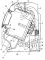
図1は、本発明の実施の形態1におけるドラム式洗濯機の概略構造を示す断面図、図2(a)は、同ドラム式洗濯機に用いた循環ポンプの断面図、図2(b)は、同ドラム式洗濯機に用いた循環ポンプの側面図、図3(a)は、同ドラム式洗濯機の水槽の要部斜視図、図3(b)は、同ドラム式洗濯機の水槽の前面壁を内方より見た平面図、図4は、同ドラム式洗濯機の水循環経路の導水路近傍の断面図、図5(a)は、同ドラム式洗濯機の水循環経路の吐出口近傍の断面図、図5(b)同ドラム式洗濯機の水循環経路の他の吐出口近傍の断面図、図6は、同ドラム式洗濯機の洗濯水の噴射の状態を示す正面図、図7は、同ドラム式洗濯機の水槽の前面壁を内方より見た平面図、図8(a)は、同ドラム式洗濯機の水循環経路の吐出口近傍の断面図、図8(b)同ドラム式洗濯機の水循環経路の他の吐出口近傍の断面図、図9(a)は、同ドラム式洗濯機の水槽の前面壁を内方より見た平面図、図9(b)同ドラム式洗濯機の水槽の前面壁を内方より見た平面図、図10(a)は、同ドラム式洗濯機の水循環経路の整流部近傍の導水路の断面図、図10(b)は、同ドラム式洗濯機の整流部及び吐出口近傍の導水路およびカバーの断面図を示すものである。
(Embodiment 1)
1 is a cross-sectional view showing a schematic structure of a drum type washing machine according to Embodiment 1 of the present invention, FIG. 2 (a) is a cross-sectional view of a circulation pump used in the drum type washing machine, and FIG. 2 (b). Fig. 3A is a side view of a circulation pump used in the drum type washing machine, Fig. 3A is a perspective view of a main part of the water tank of the drum type washing machine, and Fig. 3B is a water tank of the drum type washing machine. FIG. 4 is a cross-sectional view of the water circulation path in the vicinity of the water circulation path of the drum type washing machine, and FIG. 5A is a discharge port of the water circulation path of the drum type washing machine. FIG. 5 (b) is a cross-sectional view of the vicinity of another outlet of the water circulation path of the drum type washing machine, FIG. 6 is a front view showing a state of washing water injection of the drum type washing machine, and FIG. 7 is a plan view of the front wall of the water tank of the drum type washing machine as viewed from the inside, and FIG. 8A is a view of the vicinity of the discharge port of the water circulation path of the drum type washing machine. FIG. 8B is a sectional view of the vicinity of another outlet of the water circulation path of the drum type washing machine, and FIG. 9A is a plan view of the front wall of the water tank of the drum type washing machine as viewed from the inside. FIG. 9 (b) is a plan view of the front wall of the water tank of the drum type washing machine as seen from the inside, FIG. 10 (a) is a cross section of the water conduit near the rectifying part of the water circulation path of the drum type washing machine. FIG. 10 (b) shows a cross-sectional view of the water conduit and the cover in the vicinity of the rectifying unit and the discharge port of the drum type washing machine.
本実施の形態1のドラム式洗濯機は、モード設定や制御プログラムに従い、図1に示すモータ6、給水系7、排水系8、乾燥系9を自動制御して少なくとも洗浄工程、すすぎ工程、脱水工程、乾燥工程を行う機能を有したいわゆるドラム式洗濯乾燥機を構成している
。しかし、乾燥系9は省略することができる。また、上記に併せ、洗浄準備工程時、洗浄工程時、すすぎ工程時など必要に応じ、水循環系16にて水槽3内の洗濯水を循環させて洗剤の早期溶け込みや偏りの防止、洗濯やすすぎの機能向上を図る機能も有している。
The drum type washing machine according to the first embodiment automatically controls the motor 6, the water supply system 7, the
なお、給水系7は電磁弁の開閉によって実線矢印で示すように適時に給水でき、また給水を利用して洗剤収容部の洗剤を水槽3内に適時に投入できるようになっている。排水系8は排水弁19の開閉によって洗浄工程終了時、すすぎ工程終了時など必要なときに一点鎖線矢印で示すように排水できるようになっている。また、循環系16は水槽3内の洗濯水を循環ポンプ20により吸い込み水槽3内に戻すことを繰り返す。
Note that the water supply system 7 can supply water in a timely manner as indicated by solid arrows by opening and closing the electromagnetic valve, and the water supply can be used to supply the detergent in the detergent container into the
運転コース等のモードや各種機能の選択は、洗濯機本体2の前面上部に設けられる操作パネル21から入力して行い、制御系22がその入力情報を基に操作パネル21上の表示手段で表示して使用者に知らせるとともに、操作パネル21での入力設定手段により運転開始が設定されると、水槽3内の水位を検知する水位検知手段等からのデータを入力して駆動を開始して、排水弁、給水弁などの動作を制御し、洗浄、脱水、乾燥などの運転を行う。
The mode such as the driving course and various functions are selected by inputting from the
なお、洗濯機本体2の正面側には本体開口2bが設けられ、水槽3の正面側に設けた第2の開口13および回転ドラム4の正面側に設けた第1の開口54を介して回転ドラム4内に洗濯物を出し入れできるように構成している。本体開口2bには、開閉扉5が設けられ、水槽3の開口13をその口縁に装着したシール材14を介し密閉し、また開くことができるようにしている。
A main body opening 2 b is provided on the front side of the washing machine
なお、回転ドラム4の駆動は、回転ドラム4の90度を超え180度未満の急正弧回転、急逆弧回転を交互に繰り返す正逆弧回転駆動モードと、回転ドラム4の回転によって持ち上げられた洗濯物がその自重が勝る高さから落下する挙動を示す回転速度での前記回転ドラム4の連続回転を正逆交互に繰り返す正逆連続回転駆動モードとを備え、洗浄工程または、洗浄工程およびすすぎ工程において、前記正逆弧回転駆動モードと前記正逆連続回転駆動モードとを、交互に実行するようにしている。これにより、回転ドラム4の90度を超え180度未満の急速度での弧回転および急激な制動により洗濯物を最大限90度を超えて180度未満まで持ち上げられるし、洗濯物の持ち上げの最終段階の急激な制動により制動状態が生じて洗濯物をその慣性および自重により回転ドラム4内面から剥がしてその自重によって持ち上げ側とは左右反対の側に落すことが確実に達成できるので、洗濯水を含んで十分に膨潤し、かつ緩み、滑りやすい状態にある洗濯物に対して特に高い解し作用を与えられるし、機械力を洗濯物に及ぼすことができるので洗浄性能を高めることができる。さらに、弧回転駆動の正方向の急正弧回転と逆方向の急逆弧回転とを交互に繰り返すことで正逆弧回転駆動モードとし、これによって、正逆交互の急弧回転駆動によって洗濯物の持ち上げ位置、落下位置を毎回の弧回転駆動において左右交互に入れ換えられるので、洗濯物が絡むことをより防ぎながら解し作用をさらに高められるとともに、機械力を洗濯物に及ぼす回数を増やすことができるので洗浄性能を高めることができる。また、高い解し作用により、洗浄、すすぎ工程が進行することで生じる洗濯物同士の絡みが抑制できるので、正逆弧回転モードにおける効果的な叩き洗いを持続的に実行して、洗浄効果およびすすぎ効果を高めることができる。
The driving of the
また、正逆弧回転駆動モードのみでは、洗濯物の絡み、捩れ、皺より等が軽減される一方で、洗濯物の上下方向の位置が入れ替わりにくく、回転ドラム4底部の洗濯物は動きにくいため、洗いむらが生じやすいが、正逆連続回転駆動モードを併用することによって、洗濯物の上下方向の位置の入れ替わりを実現することができ、すなわち、正逆連続回転駆動モードにおける洗濯物の絡み、捩れ、皺よりを軽減するとともに、正逆弧回転駆動モードにおける洗濯物に対する機械力付与の不均衡を軽減することで、両モードによって洗浄
やすすぎ中の洗濯物に異なった2通りの挙動、具体的には正逆弧回転駆動モードによっては洗濯物の絡み、捩れ、皺よりを軽減しつつしっかりした手もみ洗いの挙動を、正逆連続回転駆動モードによっては洗濯物を大きく連続に動かしむらを軽減しながら洗う、均一で強い汚れに対する効果的な洗い挙動を与えられる。
Further, in the forward / reverse arc rotation drive mode alone, the tangling, twisting, wrinkles, etc. of the laundry are reduced, but the vertical position of the laundry is difficult to change, and the laundry at the bottom of the
循環ポンプ20は、台板2aに固定し、水循環経路16の循環ポンプ20からの吐出側経路16bは、水槽3の開口13が位置する洗濯機本体2の前方に向けて延びたものとしている。具体的には、循環ポンプ20は、図2に示すようにインペラ20aを収容した樹脂製のポンプケーシング20bがその開口側で、循環モータ20cのモータケーシング20dの前端にある軸受隔壁20d1に当てがって一体化し、インペラ20aをモータ軸20eに直結したものとしてあり、これを樹脂製の取り付け座35に嵌め付けてある。
The
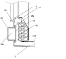
水槽3の前面壁3hの下半分の部分には、略Y字状に形成され前方に膨出した膨出部3aが形成され、膨出部3aと外形が略同一形状のカバー55が、内方より、パッキン55aを間に挟んで、ネジの締結などにより取り付けられることで、導水路55bを形成している。
The lower half of the
膨出部3aの下端部には、横方向に延びた連結部51の一端が接続され、連結部51の他端は、水循環経路16の吐出側経路16bが接続されている。また、略Y字状に形成されたカバー55のそれぞれの上端部分は、パッキン55aを含めたシール構成の無い切欠き部55cが形成され、それによって、膨出部3aとカバー55とで略Y字状に分岐して形成された導水路55bのそれぞれの上端部分には、切欠き部55cとこれに対応する水槽3の前端壁3hの裏面との間で周方向域に広がった開口を有する吐出口55dが形成されている。
One end of a connecting
循環ポンプ20により加圧された洗濯水は、水循環経路16の吐出側経路16bを介して連結部51より導水路55bに流入し、吐出口55dより水槽3の前端壁3hの裏面とこれに対応する回転ドラム4の前端壁4bの表面との間に洗濯水を噴射し、それらの間で形成する流路52を通じて回転ドラム4内に吐出するようにしてある。吐出口55dは、水槽3の前端壁3hの裏面において図5(a)に示すように回転ドラム4の回転中心方向、具体的には、水槽3の前端壁3hおよび回転ドラム4の前端壁4b間の流路52における環状の噴射口53に向かって開口しているので、吐出口55dから噴射する洗濯水は流路52を回転ドラム4の回転中心側、具体的には噴射口53に向かって径方向に回転ドラム4の内側回転域に効率よく吐出させられ、洗濯物の多少にかかわらず洗濯水を効率よく供与できる。
Washing water pressurized by the
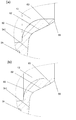
特に、水槽3の前端壁3hは吐出口55dに対応する位置から内周近くに向かって洗濯機本体2の後部側に傾斜した傾斜面3h1およびこの傾斜面3h1から内周まで、回転ドラム4の開口54側に向け傾斜した案内面56を有していることにより、流路52に噴射される洗濯水を図5(a)に示すように、傾斜面3h1から案内面56に沿わせて、噴射口53から回転ドラム4の開口54を通じ回転ドラム4の奥側に向け吐出させられるので、洗濯水の洗濯物への供与効率を高められる。
In particular, the
ここで、図5(a)、(b)に示すように、複数の吐出口55dに対し、それぞれ傾斜角度の異なる案内面56、57を設ける構成としている。例えば、図5(a)に示すように、分岐した導水路55bの正面から見て左側の吐出口55d(図3(b)における右側)に対応する案内面56の傾斜角度をαとし、また、図5(b)に示すように、導水路55bの正面から見て右側の吐出口55d(図3(b)における左側)に対応する案内面57の傾斜角度をβとして、α>βとすることで、図6に示すように、正面から見て左側の噴射口53からの洗濯水(図5(a)に示す矢印a)は、シャワー形状Aのように比較的
上方向に噴射し、一方、正面から見て右側の噴射口53からの洗濯水(図5(b)に示す矢印b)は、シャワー形状Bのように、シャワー形状Aよりも下方向に向けて噴射することとなる。すなわち、それぞれの吐出口55dから噴射された洗濯水は、傾斜角度の異なる案内面56、57に沿って流れ、噴射口53から第1の開口54を介して回転ドラム4内に噴射されるため、回転ドラム4の回転軸に対する噴射角度の異なる噴射を実現できる。
Here, as shown in FIGS. 5A and 5B, the guide surfaces 56 and 57 having different inclination angles are provided for the plurality of
また、傾斜角度は、噴射の拡がりにも影響する。傾斜角度が小さい場合、傾斜面3h1から案内面57に角度が変化する近傍で、傾斜面3h1に沿って流れてきた洗濯水が案内面57で急激に角度が変わるため、案内面57に衝突する状態となる。この状態では、案内面57に沿う流れとともに、周方向への拡がりが発生し、拡がりを有した噴射となる。すなわち、図6に示すように、傾斜角度がαである左側の噴射口53から噴射する洗濯水のシャワー形状Aに対し、傾斜角度がβ(上記のように、α>βの関係を有する)である右側の噴射口53から噴射する洗濯水のシャワー形状Bの方が、拡がりを有した噴射となっている。発明者らの試験結果では、傾斜角が120度付近までは、大きく拡がり拡散した噴射となり、130度以上では、拡がりの小さい膜状の噴射となった。
The tilt angle also affects the spread of the injection. When the angle of inclination is small, the wash water flowing along the inclined surface 3h1 changes abruptly at the
また、図7に示すように、吐出口55dの開口幅を変えることで、それぞれの吐出口55dからの洗濯水の噴射の幅や流量が異なる噴射が実現可能となり、吐出口55dから幅や流量が異なる噴射は、案内面56に沿わせて、噴射口53から回転ドラム4の開口54を通じ回転ドラム4の奥側に向け吐出させられるので、低容量や高容量の洗濯物それぞれに最適な流量や拡がり角度を設けることが可能になり、洗浄効果を高めることが可能となるとともに、効率的に洗浄水を衣類に供給することが可能となり節水を実現することが可能となる。
Further, as shown in FIG. 7, by changing the opening width of the
また、図8(a)、(b)に示すように、吐出口55dは、回転ドラム4の略回転中心側に向け所定の周方向範囲で開口し、その開口の回転軸方向の幅を二種類以上にすることにより、吐出口55dの開口の回転軸方向の幅により、噴射の流量が決まるため、開口の回転軸方向の幅を二種類以上にすることで、それぞれの噴射口53からの洗濯水の噴射の流量が異なる噴射が実現可能となる。
Further, as shown in FIGS. 8A and 8B, the
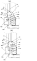
さらに、図9(a)に示すように、吐出口55d1の開口方向(矢印c)は、回転ドラム4の回転中心oに対し所定の角度ξ上方向にずらしている。これによって、吐出口55d1からの吐出の中心(矢印c)が回転ドラム4の回転中心oに対し所定の角度ξを持って吐出されるため、噴射口53からの噴射の中心(矢印c)が回転ドラム4の回転中心oに対し所定の角度ξを持って噴射される。そして、案内面56は回転ドラム4の回転中心oを中心に環状に構成されているため、吐出口55d1から噴射された洗浄水が通過する案内面56の断面形状は、回転中心oに対する案内面56の断面形状が同一であっても、回転ドラム4の回転中心oから角度があるほど緩やかになり周方向に拡がりやすくなるため、拡がり角の大きな噴射を実現することが可能となる。
Further, as shown in FIG. 9A, the opening direction (arrow c) of the discharge port 55d1 is shifted upward by a predetermined angle ξ with respect to the rotation center o of the
そして、吐出口55dの吐出の中心(矢印d)は、回転ドラム4の回転中心oに向って開口するように構成することで、左右で拡がりの異なった噴射形状を実現することができる。
Further, by configuring the discharge center (arrow d) of the
また、図9(b)に示すように、吐出口55d2には、開口方向(矢印e)を、回転ドラム4の回転中心oに対し所定の角度σ上方向にずらすように案内部65を設けている。これによって、吐出口55d2からの吐出の中心(矢印e)が回転ドラム4の回転中心oに対し所定の角度σを持って吐出されるため、噴射口53からの噴射の中心(矢印e)が回転ドラム4の回転中心oに対し所定の角度σを持って噴射される。そして、案内面57
は回転ドラム4の回転中心oを中心に環状に構成されているため、吐出口55d2から噴射された洗浄水が通過する案内面57の断面形状は、回転中心に対する案内面57の断面形状が同一であっても、回転ドラム4の回転中心oから角度があるほど緩やかになり周方向に拡がりやすくなるため、拡がり角の大きな噴射を実現することが可能となる。
9B, the discharge port 55d2 is provided with a
Is formed in an annular shape around the rotation center o of the
さらに、図9(a)、(b)および図10(a)、(b)に示すように、吐出口55dの少なくとも一方の導水路55b内の上流側近傍には、洗濯水の流れ方向に吐出口55dと重なるリブ66をカバー55に設けている。通常、導水路55bに沿って流れてきた洗濯水は、吐出口55dから吐出される際、導水路55bの長手方向の速度成分の影響で、吐出口55dや案内部65の開口方向に対して導水路55bの長手方向に角度を有した吐出となってしまう傾向がある。本実施の形態1では、上記したように、吐出口55dの導水路55b内の上流側近傍に、洗濯水の流れ方向に吐出口55dに重なるリブ66を設けているので、導水路55bに沿って流れてきた洗濯水がリブ66に衝突することで、吐出口55dから吐出する洗濯水の導水路55bの長手方向の速度成分が抑制され、吐出口55dより開口した方向に所定の角度で吐出を行うことができ、安定した所定の拡がり角の大きな噴射を実現することが可能となる。
Further, as shown in FIGS. 9A and 9B and FIGS. 10A and 10B, in the vicinity of the upstream side in at least one
上記の構成により、噴射口53からの洗濯水の回転ドラム4の回転軸に対する噴射角度を異ならせるとともに、異なる拡がりとすることで、低容量や高容量の洗濯物のそれぞれに対応した最適な噴射角度を設けることが可能となる。
With the above configuration, the spray angle from the
例えば、洗浄開始時の洗濯物が洗浄液を含んでいない状態でかさばっている際に、図6に示す左側の噴射口53近傍が洗濯物によって周方向に塞がれた場合でも、右側の噴射口53から回転ドラム4の第1の開口54付近に向けて大きな拡がりを有する噴射を行い、噴射口53近傍の洗濯物を早期に濡らし体積を減らすことで、洗濯物による左側の噴射口53近傍の塞ぎを解消することができる。
For example, when the laundry at the start of washing is bulky without containing the cleaning liquid, even if the vicinity of the
また、図6に示す左側の噴射口53からは回転ドラム4の中心軸方向に向かって拡がりが小さく回転ドラム4の奥方向に向けた噴射を行うことで、右側の噴射口53からの大きな拡がりを有する噴射では濡れにくい回転ドラム4の中心付近から奥部分の洗濯物も早期に濡らし、洗濯水の効果を高めるとともに、中心付近から奥部分の洗濯物の体積を洗濯水を染み込ませることで減らし、回転ドラム4内で洗濯物が早期に動きやすくなるので、叩き洗いの効果も向上するとともに、洗濯物の体積が減ることによりできた隙間から洗濯物全体への噴射が可能となり相乗的に洗浄効果を高めることが可能となる。
Further, from the
以上の効果により、回転ドラム4内の洗濯物にその多少にかかわらず洗浄液を有効に働かせさられ、また吐出口55dが回転ドラム4内の洗濯物と接触しない位置にあるので、洗濯物が引っ掛かって洗い、すすぎ、乾燥などに必要な挙動を乱したり、あるいは洗濯物を傷めたり、破れたりするようなことを防止することができるし、見栄えのよい外観が損なわれない。洗濯水の噴射効果は、正逆連続回転駆動モードで上下が入れ替わる洗濯物の挙動、正逆弧回転駆動モード時の左右が入れ替わる洗濯物の挙動との組合せでより高められる。
Due to the above-described effects, the washing liquid is effectively applied to the laundry in the
なお、本実施の形態1では、吐出口55dは左右の2箇所としたが、3箇所以上としても、同等の効果を有することは言うまでも無い。
In the first embodiment, the
(実施の形態2)
図11(a)は、本発明の実施の形態2におけるドラム式洗濯機の水循環経路の吐出口近傍の断面図、図11(b)は、同ドラム式洗濯機の水循環経路の他の吐出口近傍の断面図を示すものである。実施の形態1と同一構成については、同一符号を付し、その説明を
省略する。
(Embodiment 2)
11A is a cross-sectional view of the vicinity of the discharge port of the water circulation path of the drum type washing machine in
図11(a)、(b)に示すように、案内面58、59は湾曲形状とし、左右の吐出口55dに対し、それぞれ湾曲半径の異なる案内面58、59としている。例えば、図11(a)に示すように、分岐した導水路55bの正面から見て左側の吐出口55d(図3(b)における右側)に対応する案内面58の湾曲半径をγとし、また、図11(b)に示すように、導水路55bの正面から見て右側の吐出口55d(図3(b)における左側)に対応する案内面59の湾曲半径をδとして、γ>δとすることで、図6に示すように、正面から見て左側の噴射口53からの洗濯水(図11(a)に示す矢印f)は、シャワー形状Aのように比較的上方向に噴射し、一方、正面から見て右側の噴射口53からの洗濯水(図11(b)に示す矢印g)は、シャワー形状Bのように、シャワー形状Aよりも下方向に向けて噴射することとなる。すなわち、それぞれの吐出口55dから噴射された洗濯水は、湾曲半径の異なる案内面58、59に沿って流れ、噴射口53から第1の開口54を介して回転ドラム4内に噴射されるため、回転ドラム4の回転軸に対する噴射角度の異なる噴射を実現できる。
As shown in FIGS. 11A and 11B, the guide surfaces 58 and 59 are curved, and the guide surfaces 58 and 59 have different curvature radii with respect to the left and
また、湾曲半径は、噴射の拡がりにも影響する。湾曲半径が小さい場合、傾斜面3h1から案内面59に変化する近傍で、傾斜面3h1に沿って流れてきた洗濯水が案内面59の湾曲で急激に角度が変わるため、案内面59に衝突する状態となる。この状態では、案内面59に沿う流れとともに、周方向への拡がりが発生し、拡がりを有した噴射となる。すなわち、図6に示すように、湾曲半径がγである左側の噴射口53から噴射する洗濯水のシャワー形状Aに対し、傾斜角度がδ(上記のように、γ>δの関係を有する)である右側の噴射口53から噴射する洗濯水のシャワー形状Bの方が、拡がりを有した噴射となっている。
The radius of curvature also affects the spread of injection. When the radius of curvature is small, the washing water flowing along the inclined surface 3h1 suddenly changes its angle due to the curvature of the
すなわち、本実施の形態2においても、上記実施の形態1と同等の作用効果を有することができる。 In other words, the second embodiment can have the same effects as those of the first embodiment.
(実施の形態3)
図12(a)は、本発明の実施の形態3におけるドラム式洗濯機の水循環経路の吐出口近傍の断面図を示すものである。実施の形態1と同一構成については、同一符号を付し、その説明を省略する。
(Embodiment 3)
Fig.12 (a) shows sectional drawing of the discharge outlet vicinity of the water circulation path | route of the drum type washing machine in
図12に示すように、傾斜面3h1と傾斜角度の異なる案内面61とを湾曲面60で接続するように構成している。これにより、吐出口55dから吐出した洗濯水は、傾斜面3h1から湾曲面60を介して傾斜角度の異なる案内面61へスムーズに流れるため、噴射口53からの噴射が、より安定した噴射となることを実現することができる。
As shown in FIG. 12, the
また、噴射の回転ドラム4の回転軸に対する噴射角度は案内面61の傾斜角度で決め、湾曲面60の湾曲半径で噴射の拡がり角度が決めることが個別にできるようになり、噴射の拡がり角度を広げながら噴射角度を立てたり、噴射の拡がり角度を抑えながら噴射角度を寝かすことが可能となり、湾曲面60と案内面61の形状を二種類以上にすることで、それぞれの噴射口からの洗濯水の噴射の回転ドラムの回転軸に対する噴射角度や、噴射の拡がり角度が異なる噴射が実現可能となる。
Further, the injection angle of the injection with respect to the rotation axis of the
(実施の形態4)
図13は、本発明の実施の形態4におけるドラム式洗濯機の水循環経路の吐出口近傍の断面図を示すものである。実施の形態1と同一構成については、同一符号を付し、その説明を省略する。
(Embodiment 4)
FIG. 13: shows sectional drawing of the discharge port vicinity of the water circulation path | route of the drum type washing machine in
図13に示すように、本実施の形態4では、案内面を複数の傾斜角度を持つ面で構成している。 As shown in FIG. 13, in the fourth embodiment, the guide surface is composed of surfaces having a plurality of inclination angles.
図13において、傾斜面3h1から湾曲面60を介して案内面62に変化する近傍では傾斜角εを小さくとり、傾斜面3h1に沿って流れてきた洗濯水を案内面62で急激に角度を変え、案内面62に衝突させ洗濯水の流れを拡げ、傾斜角εに比べ大きい傾斜角ζの案内面63で回転ドラム4の回転軸に対する噴射角度が大きい噴射を実現する。傾斜角εと傾斜角ζの差が大きく、洗濯水の流れが案内面63に対し剥離が生じ噴射が不安定な場合は、さらに中間の傾斜角を有した面を間に追加してもよい。これらの形状は、案内面62、63近傍の偏肉を抑えることもできる。回転ドラム4の回転軸に対する噴射角度が大きく且つ拡がりを持った噴射を実現する際などに、案内面を複数の傾斜角度を持つ面で構成してもよい。
In FIG. 13, in the vicinity where the
(実施の形態5)
図14(a)は、本発明の実施の形態5におけるドラム式洗濯機の水循環経路の吐出口近傍の拡大断面図、図14(b)は、同ドラム式洗濯機の水循環経路の他の吐出口近傍の拡大断面図を示すものである。実施の形態1と同一構成については、同一符号を付し、その説明を省略する。
(Embodiment 5)
14A is an enlarged cross-sectional view of the vicinity of the discharge port of the water circulation path of the drum type washing machine in
図14(a)に示すように、洗濯水の回転ドラム4の回転軸に対する噴射角度は、開口54近傍の案内面56の、延長線上あるいは接線方向で決まることから、前端壁3hの裏面の端部は所定角の面取り形状65にすることで噴射角度を変えてもよく、また面取り形状65により洗濯物を傷めたり、破れたりするようなことを防止する効果も得られる。同様に図13(b)に示すように面取り形状65を丸み形状66としてもよい。
As shown in FIG. 14 (a), the spray angle with respect to the rotation axis of the
(実施の形態6)
図15は、本発明の実施の形態6におけるドラム式洗濯機の水循環経路の吐出口近傍の断面図を示すものである。実施の形態1と同一構成については、同一符号を付し、その説明を省略する。
(Embodiment 6)
FIG. 15 is a sectional view of the vicinity of the discharge port of the water circulation path of the drum type washing machine in the sixth embodiment of the present invention. About the same structure as Embodiment 1, the same code | symbol is attached | subjected and the description is abbreviate | omitted.
図15に示すように、噴射の拡がり、噴射角度、噴射の安定性、洗濯物の傷み、破れ、偏肉を考慮した、複数の傾斜角を持つ傾斜面64、64aや湾曲面60、60a、60b、60c、端部などを徐変し構成してもよい。
As shown in FIG. 15, inclined surfaces 64 and 64a having a plurality of inclination angles and
本発明にかかるドラム式洗濯機は、低容量や高容量の洗濯物それぞれに最適な噴射角度や拡がり角度を設けることが可能になり、洗浄効果を高めることが可能となるので、有底円筒形に形成された回転ドラムを、開口する正面側から底部となる背面側に向けて回転軸方向が水平または水平方向から下向き傾斜となるようにして水槽内に設置し、回転ドラムを回転駆動することにより回転ドラム内に収容した洗濯物を洗濯するドラム式洗濯機等として有用である。 The drum type washing machine according to the present invention can provide an optimum spray angle and spread angle for each of low-capacity and high-capacity laundry, and can improve the cleaning effect. The rotating drum formed in the above is installed in the water tank so that the rotation axis direction is horizontal or inclined downward from the horizontal direction from the opening front side to the bottom rear side, and the rotation drum is driven to rotate. Thus, the present invention is useful as a drum-type washing machine for washing laundry stored in a rotating drum.
4 回転ドラム
53 噴射口
55d 吐出口
4 Rotating
Claims (6)
前記水循環系は、前記水槽の前端壁に設けられ前記循環経路の循環ポンプからの吐出側経路が接続される導水路と、前記導水路に設けられ洗濯水を前記水槽の前端壁裏面と前記回転ドラムの前端壁表面との間に吐出させる複数の吐出口と、前記水槽の前端壁裏面と前記回転ドラムの前端壁表面との間から前記回転ドラム内に洗濯水を噴射する複数の噴射口とを設け、前記吐出口は、前記水槽の前端壁裏面と前記回転ドラムの前端壁表面との間に前記回転ドラムの略回転中心側に向け所定の周方向範囲で開口し、前記水槽の前端壁の裏面は、前記第2の開口の周端部に設けられ前記吐出口から吐出した洗濯水が前記第1の開口を介して前記回転ドラム内方向に向かうようにする案内面を有し、前記吐出口から吐出された洗濯水は前記水槽の前端壁の裏面と案内面に沿って流れ、前記噴射口から噴射される構成とし、前記吐出口の形状は少なくとも二種類以上からなることを特徴とするドラム式洗濯機。 A rotating drum having a first opening on the front side and having a bottomed cylindrical shape, and a rear surface side having a second opening corresponding to the first opening and the rotating drum from the front side to the bottom. A water tank installed so that the rotation axis direction is horizontal or inclined downward from the horizontal direction, a motor for controlling the rotation of the rotary drum, and the wash water in the water tank circulate through a circulation path connected to the water tank A drum-type washing machine including a water circulation system that circulates in the rotating drum by a pump, and that can drive at least one of a washing step and a rinsing step by driving the motor, the circulation pump, and the like.
The water circulation system is provided in a front end wall of the water tank and connected to a discharge-side path from a circulation pump of the circulation path, and the washing water provided in the water supply path and the back surface of the front end wall of the water tank and the rotation A plurality of outlets for discharging between the front end wall surface of the drum, and a plurality of outlets for injecting wash water into the rotary drum from between the front end wall back surface of the water tank and the front end wall surface of the rotary drum; The discharge port is opened in a predetermined circumferential range toward the substantially rotation center side of the rotating drum between the back surface of the front end wall of the water tank and the front end wall surface of the rotating drum, and the front end wall of the water tank A back surface of the second opening has a guide surface that is provided at a peripheral end of the second opening so that the washing water discharged from the discharge port is directed inward in the rotary drum through the first opening; The washing water discharged from the discharge port is the front end of the water tank. The back and flows along the guide surface, and configured to be injected from the injection port, wherein the shape of the discharge port is a drum type washing machine, characterized in that it consists of at least two or more kinds.
Priority Applications (7)
| Application Number | Priority Date | Filing Date | Title |
|---|---|---|---|
| JP2009196250A JP5299174B2 (en) | 2009-08-27 | 2009-08-27 | Drum washing machine |
| EP10811468.7A EP2471992B1 (en) | 2009-08-27 | 2010-08-18 | Drum type washing machine |
| CN201080038123.4A CN102482834B (en) | 2009-08-27 | 2010-08-18 | Drum type washing machine |
| PCT/JP2010/005097 WO2011024409A1 (en) | 2009-08-27 | 2010-08-18 | Drum type washing machine |
| US13/390,666 US20120137740A1 (en) | 2009-08-27 | 2010-08-18 | Drum type washing machine |
| CN201410653272.1A CN104313835B (en) | 2009-08-27 | 2010-08-18 | Tumbling-box washing machine |
| TW099128250A TW201111578A (en) | 2009-08-27 | 2010-08-24 | Drum type washing machine |
Applications Claiming Priority (1)
| Application Number | Priority Date | Filing Date | Title |
|---|---|---|---|
| JP2009196250A JP5299174B2 (en) | 2009-08-27 | 2009-08-27 | Drum washing machine |
Publications (2)
| Publication Number | Publication Date |
|---|---|
| JP2011045517A JP2011045517A (en) | 2011-03-10 |
| JP5299174B2 true JP5299174B2 (en) | 2013-09-25 |
Family
ID=43832450
Family Applications (1)
| Application Number | Title | Priority Date | Filing Date |
|---|---|---|---|
| JP2009196250A Active JP5299174B2 (en) | 2009-08-27 | 2009-08-27 | Drum washing machine |
Country Status (1)
| Country | Link |
|---|---|
| JP (1) | JP5299174B2 (en) |
Families Citing this family (5)
| Publication number | Priority date | Publication date | Assignee | Title |
|---|---|---|---|---|
| JP5279670B2 (en) * | 2009-09-11 | 2013-09-04 | 株式会社東芝 | Drum washing machine |
| JP5801949B2 (en) * | 2011-04-14 | 2015-10-28 | エルジー エレクトロニクス インコーポレイティド | Washing method |
| JP5919488B2 (en) * | 2011-09-05 | 2016-05-18 | パナソニックIpマネジメント株式会社 | Drum washing machine |
| JP6208092B2 (en) * | 2014-08-25 | 2017-10-04 | 日立アプライアンス株式会社 | Drum washing machine |
| WO2016136154A1 (en) * | 2015-02-27 | 2016-09-01 | パナソニックIpマネジメント株式会社 | Washing machine |
Family Cites Families (4)
| Publication number | Priority date | Publication date | Assignee | Title |
|---|---|---|---|---|
| JPH09299684A (en) * | 1996-05-16 | 1997-11-25 | Matsushita Electric Ind Co Ltd | Washing machine |
| JP4379265B2 (en) * | 2004-09-06 | 2009-12-09 | パナソニック株式会社 | Drum washing machine |
| KR100765277B1 (en) * | 2005-01-10 | 2007-10-09 | 엘지전자 주식회사 | drum type washer |
| JP5489328B2 (en) * | 2009-08-24 | 2014-05-14 | 株式会社東芝 | Drum washing machine |
-
2009
- 2009-08-27 JP JP2009196250A patent/JP5299174B2/en active Active
Also Published As
| Publication number | Publication date |
|---|---|
| JP2011045517A (en) | 2011-03-10 |
Similar Documents
| Publication | Publication Date | Title |
|---|---|---|
| JP5497903B2 (en) | Laundry processing equipment | |
| WO2011024409A1 (en) | Drum type washing machine | |
| TWI320066B (en) | ||
| JP5299174B2 (en) | Drum washing machine | |
| WO2011030540A1 (en) | Drum type washing machine | |
| WO2013035278A1 (en) | Drum-type washing machine | |
| JP2011115359A (en) | Drum type washing machine | |
| KR102577756B1 (en) | Method for controlling washing machine | |
| WO2013035277A1 (en) | Drum-type washing machine | |
| JP5397093B2 (en) | Drum washing machine | |
| JP4973707B2 (en) | Drum washing machine | |
| JP2014045932A (en) | Drum type washing machine | |
| JP5982651B2 (en) | Drum washing machine | |
| JP2011055977A (en) | Drum type washing machine | |
| JP6260008B2 (en) | Drum washing machine | |
| CN113748237A (en) | Drum washing machine | |
| JP5397092B2 (en) | Drum washing machine | |
| JP5891407B2 (en) | Drum washing machine | |
| JP6260009B2 (en) | Drum washing machine | |
| JP5824663B2 (en) | Drum washing machine | |
| JP2014195741A (en) | Drum type washing machine | |
| TWI715936B (en) | Sprinkler and washing machine using it | |
| JP5253488B2 (en) | Washing machine | |
| CN113748239A (en) | Drum washing machine | |
| KR20200026061A (en) | Washing machine and controlling method therefor |
Legal Events
| Date | Code | Title | Description |
|---|---|---|---|
| A621 | Written request for application examination |
Free format text: JAPANESE INTERMEDIATE CODE: A621 Effective date: 20120827 |
|
| RD01 | Notification of change of attorney |
Free format text: JAPANESE INTERMEDIATE CODE: A7421 Effective date: 20121217 |
|
| TRDD | Decision of grant or rejection written | ||
| A01 | Written decision to grant a patent or to grant a registration (utility model) |
Free format text: JAPANESE INTERMEDIATE CODE: A01 Effective date: 20130521 |
|
| A61 | First payment of annual fees (during grant procedure) |
Free format text: JAPANESE INTERMEDIATE CODE: A61 Effective date: 20130603 |
|
| R151 | Written notification of patent or utility model registration |
Ref document number: 5299174 Country of ref document: JP Free format text: JAPANESE INTERMEDIATE CODE: R151 |