WO2013035277A1 - Drum-type washing machine - Google Patents
Drum-type washing machine Download PDFInfo
- Publication number
- WO2013035277A1 WO2013035277A1 PCT/JP2012/005477 JP2012005477W WO2013035277A1 WO 2013035277 A1 WO2013035277 A1 WO 2013035277A1 JP 2012005477 W JP2012005477 W JP 2012005477W WO 2013035277 A1 WO2013035277 A1 WO 2013035277A1
- Authority
- WO
- WIPO (PCT)
- Prior art keywords
- water
- tank
- washing
- nozzle
- rotation
- Prior art date
Links
Images


Classifications
-
- D—TEXTILES; PAPER
- D06—TREATMENT OF TEXTILES OR THE LIKE; LAUNDERING; FLEXIBLE MATERIALS NOT OTHERWISE PROVIDED FOR
- D06F—LAUNDERING, DRYING, IRONING, PRESSING OR FOLDING TEXTILE ARTICLES
- D06F35/00—Washing machines, apparatus, or methods not otherwise provided for
- D06F35/005—Methods for washing, rinsing or spin-drying
- D06F35/006—Methods for washing, rinsing or spin-drying for washing or rinsing only
-
- D—TEXTILES; PAPER
- D06—TREATMENT OF TEXTILES OR THE LIKE; LAUNDERING; FLEXIBLE MATERIALS NOT OTHERWISE PROVIDED FOR
- D06F—LAUNDERING, DRYING, IRONING, PRESSING OR FOLDING TEXTILE ARTICLES
- D06F39/00—Details of washing machines not specific to a single type of machines covered by groups D06F9/00 - D06F27/00
- D06F39/08—Liquid supply or discharge arrangements
- D06F39/083—Liquid discharge or recirculation arrangements
-
- D—TEXTILES; PAPER
- D06—TREATMENT OF TEXTILES OR THE LIKE; LAUNDERING; FLEXIBLE MATERIALS NOT OTHERWISE PROVIDED FOR
- D06F—LAUNDERING, DRYING, IRONING, PRESSING OR FOLDING TEXTILE ARTICLES
- D06F39/00—Details of washing machines not specific to a single type of machines covered by groups D06F9/00 - D06F27/00
- D06F39/08—Liquid supply or discharge arrangements
- D06F39/088—Liquid supply arrangements
Definitions
- the present invention relates to a drum-type washing machine for washing clothes and the like.
- a conventional drum-type washing machine uses less water than a vertical washing machine, and part of the laundry in the water tank is not immersed in the washing water, so the washing water in the water tank is circulated by the pump into the rotating tank It spouts into the laundry (see, for example, Patent Document 1).
- washing water is ejected from a plurality of jet outlets formed by changing the angle little by little from the front side of the rotating tank to the center side of the rotating tank.
- the jet nozzle is provided above the front side of the rotary tank, and jets washing water downward. For this reason, even if the washing water is spouted from a plurality of jet outlets by changing the angle little by little in the depth direction of the rotation tank, the washing water is evenly applied to the laundry present at various positions in the rotation tank. I had the problem that I could not do it. In addition, even if washing water can be poured evenly in the rotation tank, if a large amount of laundry is accommodated in the rotation tank, the washing water is supplied only to the laundry on the surface near the jet outlet, Washing water is difficult to spread to the laundry located inside the mass of laundry. Therefore, it had the subject that sufficient washing
- the drum type washing machine comprises a water tank for storing washing water, a rotary tank rotatably disposed in the water tank and having an opening on the front side, a motor for driving the rotary tank, washing water in the water tank And a pump water passage that communicates with the circulating water passage and is provided in a substantially circular shape on the outer side of the peripheral portion of the opening of the rotating tank. And a plurality of nozzles provided in the nozzle channel so as to spout the washing water supplied by the pump toward the inside of the rotation tank, and a control unit which drives the motor and the pump to perform the washing step. .
- the washing step includes a first rotation step in which the laundry in the rotation tank rotates at a speed not to stick to the inner peripheral wall of the rotation tank, and a speed at which the laundry in the rotation tank sticks to the inner peripheral wall of the rotation tank And a second rotation step of rotating.
- the control unit drives the pump to supply wash water to the laundry stuck to the inner peripheral wall of the rotation tank.
- the washing water supplied into the water tank by the pump continues to be supplied uniformly not only to a part of the laundry in the vicinity of the spout but also to the entire laundry stuck to the inner peripheral wall in the rotating tank. be able to.
- the washing efficiency can be enhanced.
- FIG. 1 is a cross-sectional view showing a schematic structure of a drum-type washing machine according to Embodiment 1 of the present invention.
- FIG. 2 is a cross-sectional view of an essential part of the drum-type washing machine according to the first embodiment of the present invention.
- FIG. 3 is a view on arrow 3-3 of FIG. 1 of the drum type washing machine according to the first embodiment of the present invention.
- FIG. 4 is a cross-sectional view of the nozzle of the drum-type washing machine in the first embodiment of the present invention.
- FIG. 5 is a cross-sectional view of a conventional nozzle.
- FIG. 6A is a schematic view showing the condition of the laundry in the rotary tub of the drum-type washing machine according to the first embodiment of the present invention.
- FIG. 6A is a schematic view showing the condition of the laundry in the rotary tub of the drum-type washing machine according to the first embodiment of the present invention.
- FIG. 6B is a schematic view showing the condition of the laundry in the rotary tub of the drum-type washing machine in the first embodiment of the present invention.
- FIG. 6C is a schematic view showing the condition of the laundry in the rotary tub of the drum-type washing machine in the first embodiment of the present invention.
- FIG. 7: is a schematic diagram which shows the condition of the laundry in the case of injecting circulating water from one nozzle.
- FIG. 8 is a schematic view showing the condition of the laundry in the case where the circulating water is sprayed from the plurality of nozzles of the drum-type washing machine in the first embodiment of the present invention.
- FIG. 9A is a time chart showing the operation of the washing process of the drum-type washing machine in the first embodiment of the present invention.
- FIG. 9B is a time chart showing the operation of the washing process of the drum-type washing machine in the first embodiment of the present invention.
- FIG. 9C is a time chart showing the operation of the washing process of the drum-type washing machine in the first
- FIG. 1 is a cross-sectional view showing a schematic structure of a drum-type washing machine according to a first embodiment of the present invention.
- FIG. 2 is a cross-sectional view of an essential part of the drum-type washing machine according to the first embodiment of the present invention.
- FIG. 3 is a view on arrow 3-3 of FIG. 1 of the drum type washing machine in the first embodiment of the present invention.
- FIG. 4 is a cross-sectional view of the nozzle of the drum-type washing machine in the first embodiment of the present invention.
- a water tank 2 formed in a bottomed cylindrical shape is elastically supported in a housing 1.
- a rotary tank 4 formed in a cylindrical shape with a bottom is rotatably disposed in the water tank 2.
- the rotation axis 10 of the rotation tank 4 substantially coincides with the cylindrical center line of the rotation tank 4, which also substantially coincides with the cylinder center line of the water tank 2.
- the water tank 2 and the rotary tank 4 are provided with openings 5 and 6 on the front side respectively.
- the rotation axis 10 of the rotation tank 4 is supported by being inclined forward (for example, 10 to 20 degrees) from the horizontal direction.
- the rotation axis 10 may be horizontal.
- a door 7 that can be opened and closed is provided on the front surface of the housing 1 so as to face the opening 5 of the water tank 2 and the opening 6 of the rotating tank 4.
- the user can put the laundry into and out of the rotary tub 4 by opening the door 7.
- a flexible bellows 8, for example, formed of an elastic material such as rubber is disposed around the opening 5 of the water tank 2.
- a motor 9 for driving the rotation tank 4 is attached.
- the rotor of the motor 9 is connected to the rotation tank 4 at the rotation axis 10 of the rotation tank 4, and the rotation of the motor 9 is transmitted to the rotation tank 4 by the rotation axis 10.
- a plurality of protrusions 12 are provided on the peripheral wall of the rotation tank 4 so as to protrude toward the rotation axis 10. The rotation of the rotation tank 4 causes the laundry to be caught by the protrusions 12 and lifted upward, thereby performing an agitation operation of dropping the laundry from a certain height.
- a plurality of small holes 13 are provided in the peripheral wall of the rotation tank 4 over the entire circumference, and when the washing water in the water tank 2 is accumulated at a predetermined water level, the washing water enters the rotation tank 4 from the small holes 13 Is configured as.
- the washing water includes the detergent component in the washing step.
- a detergent container 14 for containing a detergent is provided above the water tank 2, a detergent container 14 for containing a detergent is provided.
- the detergent container 14 is connected to a water supply valve 15 connected to a water tap. Supplying and stopping of the tap water to the detergent container 14 is performed by opening and closing the water supply valve 15. Further, a water supply path 16 for guiding the water introduced into the detergent container 14 together with the detergent into the water tank 2 is provided below the detergent container 14.
- a drainage port 17 for discharging the washing water in the water tank 2 is provided, and a drainage path 18 for leading the washing water discharged from the drainage port 17 to the outside of the housing 1 is provided.
- a drain valve 19 is provided in the middle of the drain passage 18 for opening and closing the drain passage 18.
- a circulating water passage 20 is connected to the drainage port 17 so that the washing water discharged from the water tank 2 passes through the rotation tank 4 and is led back into the water tank 2 and is branched on the way from the drainage path 18 .
- the circulating water channel 20 is disposed substantially horizontally below the water tank 2 from the lower rear of the water tank 2 toward the front.
- a pump 21 is provided in the middle of the circulating water passage 20. The pump 21 draws the wash water in the water tank 2 into the circulation water passage 20 from the drainage port 17, pressurizes the wash water flowing into the circulation water passage 20, waters it to the rotary tank 4, and circulates it to the water tank 2 through the circulation water passage 20. be able to.
- a nozzle water channel 22 is provided on the outer peripheral side of a circular opening 5 provided in the water tank 2 as viewed from the opening 6 side of the rotation tank 4.
- the nozzle water passage 22 communicates with the circulation water passage 20 and is provided in a substantially circular shape on the outer side of the peripheral portion 23 of the opening 6 provided in the rotary tank 4 in a circular shape.
- the opening 5 provided in the water tank 2, the opening 6 provided in the rotary tank 4, and the nozzle channel 22 are formed substantially concentrically.
- the inner peripheral edge 24 of the nozzle channel 22 is located radially outward of the peripheral edge 23 of the opening 6.
- the wash water in the water tank 2 supplied by the pump 21 is led from the inlet 25 provided in the nozzle channel 22 through the circulation channel 20 into the nozzle channel 22, and at least three or more provided in the nozzle channel 22. It leads to a plurality of nozzles 26 (26a to 26g) (the example of FIG. 3 is seven).
- the nozzle 26 is provided so as to eject wash water from the nozzle water channel 22 toward the rotation axis 10 side of the rotation tank 4.
- a space 27 is provided between the nozzle 26 and the peripheral portion 23 of the opening 6.
- the space portion 27 is provided with a reflection portion 28 for reflecting the cleaning water spouted from the nozzle 26 to the space portion 27 toward the opening 6.
- the reflection unit 28 is configured to guide the washing water jetted into the space 27 to the opening 6 and to be introduced into the rotation tank 4.
- the plurality of nozzles 26 (26a to 26g) are formed at positions away from the peripheral portion 23 of the opening 6 of the rotary tank 4. As a result, it is possible to apply the diffused washing water to the laundry in the rotary tank 4 without exposing the nozzle 26 to the opening 6 of the rotary tank 4. As a result, when the laundry is put into the rotary tub 4 or taken out, it is not caught by the opening 6 and the laundry is not damaged, and the laundry can be easily put in and out, and the usability can be improved.
- the collision surface 28 a is configured such that the jet flow from the nozzle 26 is guided from the opening 6 of the rotation tank 4 into the rotation tank 4 while being diffused. Therefore, even if the nozzle 26 is formed at a position separated from the peripheral edge 23 of the opening 6 of the rotation tank 4, the jet flow from the nozzle 26 is guided into the rotation tank 4 without receiving unnecessary wall resistance. .
- Such a configuration makes it possible to minimize the decrease in the flow rate of the washing water, and it is possible to supply the washing water to the laundry in the rotary tank 4 vigorously.
- the nozzle 26 has a round hole shape because it is not necessary to have a flat shape in order to be along the water guiding wall surface.
- the round hole shape is the shape having the smallest pressure loss if it has the same cross-sectional area.
- the reflective portion 28 is annularly disposed around the opening 5 so as to face the front surface portion of the rotary tank 4.
- the collision surface 28 a against which the cleaning water ejected from the nozzle 26 collides is an inclined surface which is inclined with respect to the jet direction from the nozzle 26.
- the jet from the nozzle 26 can be stably landed on the collision surface 28 a without being scattered in the collision surface 28 a in multiple directions, and can be diffused while flowing along the inclined surface. For this reason, washing water can be supplied to the laundry in the rotary tank 4 in a stable diffusion state.
- the jet can be more stably landed on the collision surface 28a and diffused.
- the reflecting portion 28 is constituted only by the collision surface 28a, if the inclination angle of the collision surface 28a with respect to the jet flow direction from the nozzle 26 is gentle, the jet flow can be guided to the inner back direction of the rotation tank 4 Can not. For this reason, washing water is supplied only to the front clothes in the rotating tank 4.
- a guide portion 28 b for guiding the jet stream in the inner back direction of the rotary tub 4 is provided on the inner peripheral edge of the reflecting portion 28.
- the collision surface 28 a is inclined more gently than the guide portion 28 b with respect to the direction of the jet flow from the nozzle 26.
- the reflecting portion 28 is configured such that the length for guiding the washing water in the guide portion 28b is shorter than the length for guiding the washing water on the collision surface 28a.
- the distance of the jet contact with the collision surface 28a needs to be longer than the collision range of the jet. is there.
- the function of the guide part 28b only changes the direction of the jet flow. For this reason, the distance where the jet stream contacts the guide portion 28b may be shorter than the distance where the jet stream contacts the collision surface 28a. Thereby, it is possible to minimize the decrease in the flow velocity of the jet in the guide portion 28b, to supply the washing water to the laundry in the rotary tank 4 more vigorously, and to improve the washing performance and the rinsing performance. be able to.
- the washing water supplied by the pump 21 is jetted from the plurality of nozzles 26a to 26g provided in the nozzle water channel 22 as rod-like jets toward the rotation axis 10.
- the washing water spouted into the space 27 collides with the collision surface 28 a of the reflection part 28 and is reflected toward the opening 6 of the rotation tank 4 and diffused in the rotation direction of the rotation tank 4 and by the guide 28 b
- the gas is jetted from the vicinity of the peripheral portion 23 of the opening 6 toward the inside of the rotary tank 4.
- a plurality of nozzles 26 are provided in a nozzle water passage 22 provided in a substantially circular shape on the outside of the peripheral portion 23 of the opening 6, and the jet direction of the washing water in all the nozzles 26 a to 26 g When viewed from the opening surface side of the rotary tank 4 from the direction toward 10, displacement is performed in the same direction at a predetermined displacement angle (displacement angle) ⁇ 1.
- a displacement angle (shift angle) ⁇ 1 for shifting the jet direction B of the wash water with respect to the rotation axis 10 is It is preferable to set to about half (for example, 5 to 15 degrees) of the spread angle ⁇ 2 (for example, 10 to 30 degrees) of the washing water diffused in the rotational direction of the rotation tank 4.
- the nozzle water channel 22 is provided with a bulging portion 29 in which a part of the nozzle water channel 22 is inflated toward the rotation axis 10 of the rotary tank 4.
- the nozzle 26 is configured by providing a circular nozzle hole 31 in the flat portion 30 of the bulging portion 29.
- the length L of the nozzle hole 31 is equal to or less than the diameter d of the nozzle hole 31.
- the flat portion 30 is orthogonal to the ejection direction of the cleaning water ejected from the nozzle hole 31 and inclined at the same angle as the displacement angle (shifting angle) ⁇ 1 from the direction toward the rotation axis 10 in the ejection direction of the cleaning water There is.
- the nozzles 26 (26a to 26g) are hardly affected by the main flow of washing water . Therefore, the disturbance of the jet flow ejected from the nozzles 26 (26a to 26g) can be suppressed, and the direction of the flush water to be ejected can be stabilized. Further, since the jet flow from the nozzles 26 (26a to 26g) can be contracted, the flow velocity of the jet can be increased, and the momentum of the jetted washing water can be strengthened.
- FIG. 5 is a cross-sectional view of a conventional nozzle.
- the nozzle 100 is formed so that the inner wall surface 103 of the nozzle water passage 102 gradually and smoothly becomes smaller toward the nozzle hole 101 in order to minimize pressure loss.
- the flow of water in the nozzle water channel 102 is prevented from separating from the inner wall surface 103 immediately before the jet flow spouts from the nozzle hole 101 to prevent the turbulent flow, and the efficient nozzle 100 is configured.
- the flow velocity of the jet flow from the nozzle hole 101 is determined by the cross-sectional area of the nozzle hole 101 if the flow rate of the jet flow is the same. In order to increase the flow velocity of the jet, it is necessary to increase the flow rate or reduce the cross-sectional area of the nozzle hole 101.
- the nozzle water channel 22 is provided with a bulging portion 29 expanded toward the rotation axis 10 side of the rotary tank 4, and the nozzle hole 31 is surrounded by the nozzle hole 31 in the penetrating direction A substantially vertical flat portion 30 is provided.
- the viscosity of the fluid causes the washing water to flow along the inner wall surface 22b.
- the inner wall surface 22 b is suddenly bent about 90 degrees, so the flow of the washing water is separated from the peripheral wall of the nozzle holes 31.
- the cross-sectional area C of the jet flow is smaller than the cross-sectional area D of the nozzle hole 31, that is, contracted.
- the flow velocity of the jet can be made faster than a normal nozzle. You can strengthen the momentum of
- the nozzle hole 31 has a circular shape in the EE cross section of FIG.
- the jet flow is uniformly contracted, the disturbance of the jet flow from the nozzle hole 31 can be suppressed, and the washing water can be jetted in the set direction and applied to the laundry.
- the nozzle holes 31 have no corners, it is difficult for lint and the like generated from the laundry to be caught in the nozzle holes 31, and it is possible to prevent hole clogging due to lint.
- the nozzle hole 31 has a length L of the nozzle hole 31 equal to or less than the diameter d of the nozzle hole 31. If the nozzle hole 31 is too long in the jetting direction, the flow once separated from the peripheral wall of the nozzle hole 31 and contracted is gradually spread and jetted. As a result, since the effect of increasing the flow velocity of the jet flow is lost, the length L of the nozzle hole 31 is preferably equal to or less than the diameter d of the nozzle hole 31. As a result, the flow velocity of the jet flow from the nozzle holes 31 can be reliably increased, and hence the momentum of the jetted cleaning water can be surely increased.
- the nozzle water channel 22 is branched in two directions from the inflow port 25 and configured to extend toward the end 22 a. For this reason, since the path of water flowing in the nozzle water channel 22 is divided into two, even if the nozzle water channel 22 is annularly long so as to surround the opening 5, the flow path can be shortened. Therefore, the pressure loss in the path can be reduced. Therefore, sufficient pressure can be applied to each of the nozzles 26a to 26g, and the flow velocity of the jet jetted from the nozzles 26 can be secured. Thereby, washing water can be evenly applied to the laundry in the rotary tank 4.
- the nozzle water channel 22 is the same as in the annularly formed configuration without the end 22a because it is branched from the inflow port 25 in two directions.
- the direction in which the washing water flows from the inflow port 25 into the nozzle water channel 22 is configured to be in the direction of the rotation axis 10 (arrow F) of the rotation tank 4. Therefore, the flow of washing water in two directions can be smoothly branched, and sufficient pressure can be applied to each of the nozzles 26a to 26g. Thereby, the flow velocity of the jet flow ejected from the nozzle 26 can be secured.
- a control unit that controls the motor 9, the water supply valve 15, the drain valve 19, the pump 21 and the like in the lower rear of the housing 1 and controls operations of washing, rinsing, and dewatering processes based on a set program. 32 are provided.
- 6A to 6C are schematic views showing the condition of the laundry in the rotary tub of the drum-type washing machine according to the first embodiment of the present invention.
- 9A to 9C are time charts showing the operation of the washing process of the drum-type washing machine according to the first embodiment of the present invention.
- the control unit 32 detects the amount of the loaded laundry. Thereafter, the water supply valve 15 is opened, the washing water dissolves the laundry detergent stored in the detergent container 14, and the washing water is supplied from the water supply path 16 into the water tank 2.
- the flush water stored in the water tank 2 is detected by a water level detector (not shown).
- the control unit 32 stops the water supply and starts the washing.
- the rotation tank 4 is driven to rotate in the forward and reverse directions by the motor 9, and the laundry stored in the rotation tank 4 is lifted in the rotation direction by the projections 12 provided on the cylindrical wall 11 of the rotation tank 4 and then dropped. , The laundry is washed by the action of tap washing.
- the water level of the washing water is set by the distance at which the laundry falls to the washing water so that the effect of tapping and washing can be obtained, and the washing water is stored to the lower side in the rotary tank 4.
- the water level in the water tank 2 is low, it is difficult for wash water to spread throughout the entire laundry. Therefore, when the pump 21 is operated to lower the washing water into the laundry in the rotation tank 4, the washing water in the water tank 2 is drawn into the circulating water channel 20 from the drainage port 17 provided at the bottom of the water tank 2. .
- the washing water supplied from the circulating water passage 20 to the nozzle water passage 22 through the inlet 25 is branched in two directions toward the end 22a of the nozzle water passage 22 formed in an annular shape, and the plurality of nozzles provided at equal intervals 26 (26a to 26g) and spouting while diffusing into the rotating tank 4;
- the control unit 32 operates the pump 21 to circulate the washing water in the water tank 2 and apply the washing water evenly to the laundry.
- the plurality of nozzles 26 (26a to 26g) have predetermined displacement in the same direction from the direction toward the rotation axis 10 of the rotation tank 4 when the jet direction B of the washing water is viewed from the opening surface side of the rotation tank 4 It is configured to be displaced at an angle (displacement angle) ⁇ 1. For this reason, it is possible to evenly expand the range in which wash water supplied to the water tank 2 by the pump 21 is spouted into the rotating tank 4. As a result, it is possible to increase the opportunity for washing water to be applied to the laundry being agitated and moved in the rotary tank 4, and the washing water can be continuously supplied evenly to the entire laundry in the rotary tank 4.
- At least one or more nozzles 26 g of the plurality of nozzles 26 are configured to eject the washing water from the vicinity of the upper end of the peripheral portion 23 of the opening 6 of the rotation tank 4 toward the inside of the rotation tank 4. For this reason, the washing water can be poured from the vicinity of the uppermost point of the laundry, and the washing water supplied to the upper laundry flows downward by gravity. In this process, since the washing water is also supplied to the lower laundry, the washing water can be efficiently and evenly supplied to the entire laundry.
- the tap washing is performed by a first rotation step of rotating at a speed such that the laundry in the rotation tank 4 does not stick to the inner peripheral wall of the rotation tank 4, for example, 45 r / min.
- Centrifugal cleaning is performed by a second rotation process in which the laundry in the rotation tank 4 is rotated at a speed such as 100 r / min, for example, to stick the inner peripheral wall of the rotation tank 4.
- the washing water moves from the inside to the outside of the rotation tank 4 together with the dirt and the detergent due to the centrifugal force.
- so-called centrifugal cleaning is performed by the second rotation process in which the laundry in the rotation tank 4 rotates at a speed such that the laundry sticks to the inner circumferential wall of the rotation tank 4.
- the washing water moves through the fiber together with the dirt and the detergent component from the inside to the outside of the rotation tank 4 by the centrifugal force.
- the water-soluble dirt etc. which adhered to the laundry located in the central part of the above-mentioned rotation tank 4 can be removed effectively.
- the rotation tank 4 is selected regardless of the amount of laundry in the rotation tank 4 or the type of dirt attached to the laundry. The entire laundry can be efficiently cleaned.
- the second rotation step in order to obtain the desired centrifugal cleaning effect, it is essential to carry out a plurality of second rotation steps. That is, as shown in FIG. 6B), once the washing water moves from the inside to the outside of the rotary tank 4 by the centrifugal force and passes through the fiber together with the dirt and the detergent component, even if the operation continues as it is There is no transfer of new wash water. That is, since it is necessary to supply wash water to the clothes inside the rotation tank 4 again, it is necessary to carry out the first low speed rotation step and then to carry out the second high speed rotation step again.
- the pump 21 is driven in the second rotation step as shown in FIG. 6C instead of performing the second rotation step frequently in the washing step, and the circulation water passage 20, the nozzle water passage 22, and the plurality of The washing water in the water tank 2 is constantly supplied to the laundry stuck to the inner peripheral wall of the rotation tank 4 through the nozzle 26 and the like.
- FIG. 9C even when the second rotation process is performed less frequently, for example, once or twice, the second high-speed rotation process is frequently performed without driving the pump 21.
- An equivalent centrifugal cleaning effect can be obtained.
- the pump 21 when the pump 21 is driven with the second rotation process once or twice, if the washing water is not evenly supplied to the entire laundry in the rotating tank 4 by the plurality of nozzles 26, the frequency as described above is low. The effect of the centrifugal washing by the high speed rotation process in the above can not be obtained. That is, if the washing water is not supplied to even part of the laundry stuck to the inner peripheral wall of the rotation tank 4, it is necessary to carry out the first rotation step to again supply the washing water to the laundry.
- the washing water supplied to the water tank 2 by the pump 21 is not only attached to a part of the laundry near the nozzles 26 but also attached to the inner circumferential wall in the rotating tank 4 We can continue to supply the whole thing evenly. The details will be described below.
- FIG. 7 is a schematic diagram which shows the condition of the laundry in the case of injecting circulating water from one nozzle.
- FIG. 8 is a schematic view showing the state of the laundry in the case where the circulating water is sprayed from the plurality of nozzles of the drum-type washing machine in the first embodiment of the present invention.
- each laundry item 1 to G has 1 each while the rotary tank 4 makes one rotation. Washing water is supplied only once and sufficient washing is not performed. Therefore, in order to obtain a desired cleaning effect, it is necessary to carry out the second rotation step for a long time, and it is inevitable to prolong the process time and waste power consumption.
- the pump 21 is driven, and the washing water in the water tank 2 is attached to the inner peripheral wall of the rotating tank 4 through the circulating water channel 20, the nozzle water channel 22, the plurality of nozzles 26 and the like.
- the above-mentioned subject can be avoided. That is, as shown in FIG. 8, when washing water is supplied from a plurality of nozzles, for example, seven locations of the nozzles a to g to the laundry items A to G in the rotary tank 4, the rotary tank 4 makes one revolution while Each of the laundry items A to G is repeatedly supplied with washing water seven times.
- the control unit 32 does not perform the second rotation process.
- the control unit 32 preferably does not perform the second rotation process.
- the control unit 32 opens the drain valve 19 to drain the washing water in the water tank 2 through the drain passage 18. After the drainage is completed, rinse water for rinsing is newly supplied to carry out the rinsing step.
- the operation of the rotary tank 4 in the rinsing step is the same as the washing step.
- the controller 32 opens the drain valve 19 to drain the rinse water in the water tank 2. Thereafter, the rotary tank 4 is rotated at a high speed to dewater the rinse water contained in the laundry. A dewatering process is performed for a predetermined time to complete the operation. Alternatively, a drying device may be provided and the drying step may be performed following the dewatering step.
- the washing water is spouted from a plurality of peripheral portions of the opening 6 of the rotation tank 4 to evenly supply the washing water to the laundry in the rotation tank 4 Can.
- the washing efficiency can be enhanced by spouting the above-described washing water.
- the drum-type washing machine of the present invention includes a water tank for storing washing water, a rotary tank rotatably disposed in the water tank and provided with an opening on the front side, and a motor for driving the rotary tank.
- a circulating water channel for circulating washing water in the water tank to the rotation tank, a pump for feeding washing water in the water tank to the circulation water channel, and the circulation water channel, and the outer periphery of the opening of the rotation tank is substantially circular
- a plurality of nozzles provided in the nozzle channel so as to eject the washing water supplied by the pump toward the inside of the rotary tank, the motor and the pump are driven to perform the washing step.
- a control unit for controlling washing water supplied by the pump toward the inside of the rotary tank, the motor and the pump are driven to perform the washing step.
- the washing step includes a first rotation step in which the laundry in the rotation tank rotates at a speed not to stick to the inner peripheral wall of the rotation tank, and a speed at which the laundry in the rotation tank sticks to the inner peripheral wall of the rotation tank And a second rotation step of rotating.
- the control unit drives the pump to supply wash water to the laundry stuck to the inner peripheral wall of the rotation tank.
- the washing water supplied into the water tank by the pump continues to be supplied uniformly not only to a part of the laundry in the vicinity of the spout but also to the entire laundry stuck to the inner peripheral wall in the rotating tank. be able to.
- the effect of so-called centrifugal cleaning is obtained, in which the washing water moves with dirt and detergent from the laundry inside the rotary tank toward the laundry outside the rotary tank by centrifugal force. . Therefore, by always supplying the washing water by the pump, the dewatering of the washing water by the centrifugal force and the water absorption by the circulation water (washing water) being applied are repeated, and the effect of the centrifugal washing is further promoted. Be done. As a result, the cleaning performance can be improved.
- the drum type washing machine of the present invention further includes a water level setting unit for setting the water level in the water tank.
- the control unit does not perform the second rotation process when the water level in the water tank is set higher than a predetermined level by the water level setting unit.
- a reflective portion for reflecting the washing water spouted from the nozzle to the space portion toward the opening portion is provided in the space portion between the nozzle and the peripheral portion of the opening portion.
- the reflecting portion has an impact surface inclined with respect to the jet direction of the washing water, and a guide portion provided on the inner peripheral edge to guide the jet flow which has collided with the impact surface into the rotating tank.
- the inclination of the collision surface can be set gently with respect to the direction of the jet from the nozzle. Therefore, the jet stream from the nozzle can be more stably landed on the collision surface and diffused. Thereafter, the guide portion guides the jet flow in the direction toward the inside of the rotary tank, so that washing water can be supplied to the laundry in the rotary tank in a stable diffusion state.
- the inclination angle of the collision surface with respect to the jet direction of the washing water is set to be gentler than the inclination angle of the guide with respect to the jet direction of the washing water.
- the length for guiding the washing water in the guide portion is set shorter than the length for guiding the washing water on the collision surface.
- the drum type washing machine of this invention has a bulging part which expanded a part of nozzle channel to the rotating shaft center side of a rotating tank.
- a circular nozzle hole is provided in a flat portion of the bulging portion.
- the penetration direction of the nozzle hole is substantially perpendicular to the flat portion, and the length of the nozzle hole is equal to or less than the diameter of the nozzle hole.
- the disturbance of the jet flow ejected from the nozzle can be suppressed, and the direction of the flush water to be ejected can be stabilized.
- the jet flow from the nozzle can be contracted, the flow velocity of the jet can be increased, and the force of the jetted washing water can be strengthened.
- the penetration direction of the nozzle holes is a direction displaced by a predetermined displacement angle from the direction toward the rotation axis of the rotation tank.
- the drum-type washing machine according to the present invention can uniformly supply the washing water to the entire laundry regardless of the amount of laundry in the rotating tank, and can improve the washing efficiency and the rinse efficiency. Because it can, it is useful as a drum type washing machine.
Abstract
A drum-type washing machine, comprising: a water tank (2) that stores washing water; a rotating drum (4) rotatably arranged inside the water tank (2) and having an opening (5) on the front surface side thereof; a motor (9) that drives the rotating drum (4); a circulating water path (20) that circulates, towards the rotating drum (4), washing water that is inside the water tank (2); a pump (21) that sends the washing water that is inside the water tank (2) to the circulating water path (20); a nozzle water path (22) that is connected to the circulating water path (20) and is disposed in a substantially circular shape on the outside of the peripheral edge section (23) of the opening (5) of the rotating drum (4); a plurality of nozzles (26) disposed in the nozzle water path (22) so as to spray the washing water that is supplied by the pump (21), towards the inside of the rotating drum (4); and a control unit (32) that drives the motor (9) and the pump (21), and performs the washing steps. The washing steps include: a first rotation step in which the rotating drum (4) rotates at a speed whereat the washing items inside the rotating drum (4) do not stick to the inner peripheral wall of the rotating drum (4); and a second rotation step in which the rotating drum (4) rotates at a speed whereat the washing items inside the rotating drum (4) stick to the inner peripheral wall of the rotating drum (4). In the second rotation step, the control unit (32) drives the pump (21), and supplies washing water to the washing items stuck to the inner peripheral wall of the rotating drum (4).
Description
本発明は、衣類等の洗濯をおこなうドラム式洗濯機に関する。
The present invention relates to a drum-type washing machine for washing clothes and the like.
従来のドラム式洗濯機は、縦型洗濯機よりも使用水量が少なく、水槽内の洗濯物の一部が洗浄水に浸らない為、水槽内の洗浄水をポンプによって回転槽内へ循環させて洗濯物に噴出している(例えば、特許文献1参照)。
A conventional drum-type washing machine uses less water than a vertical washing machine, and part of the laundry in the water tank is not immersed in the washing water, so the washing water in the water tank is circulated by the pump into the rotating tank It spouts into the laundry (see, for example, Patent Document 1).
特許文献1のドラム式洗濯機は、回転槽の前面側から回転槽の中心側に少しずつ角度を変えて複数形成されている噴出口より、洗浄水を噴出している。
In the drum-type washing machine of Patent Document 1, washing water is ejected from a plurality of jet outlets formed by changing the angle little by little from the front side of the rotating tank to the center side of the rotating tank.
しかしながら、上記従来の構成では、噴出口が回転槽の前面側上方に設けられ、下方に向かって洗浄水を噴出するものである。このため、回転槽の奥行き方向に少しずつ角度を変えて複数の噴出口から洗浄水を噴出するようにしても、回転槽内の様々な位置に存在する洗濯物に対して満遍なく洗浄水をかけることができないという課題を有していた。また、仮に回転槽内に満遍なく洗浄水をかけることができたとしても、回転槽内に多量の洗濯物を収容した場合は、噴出口近傍の表面にある洗濯物にのみ洗浄水が供給され、洗濯物の塊の内部に位置する洗濯物までは洗浄水が行き渡りにくい。そのため、従来のドラム式洗濯機では十分な洗浄およびすすぎ効果が得られないという課題を有していた。
However, in the above-described conventional configuration, the jet nozzle is provided above the front side of the rotary tank, and jets washing water downward. For this reason, even if the washing water is spouted from a plurality of jet outlets by changing the angle little by little in the depth direction of the rotation tank, the washing water is evenly applied to the laundry present at various positions in the rotation tank. I had the problem that I could not do it. In addition, even if washing water can be poured evenly in the rotation tank, if a large amount of laundry is accommodated in the rotation tank, the washing water is supplied only to the laundry on the surface near the jet outlet, Washing water is difficult to spread to the laundry located inside the mass of laundry. Therefore, it had the subject that sufficient washing | cleaning and the rinse effect were not acquired in the conventional drum type washing machine.
本発明のドラム式洗濯機は、洗浄水を溜める水槽と、水槽内に回転可能に配設され前面側に開口部を設けた回転槽と、回転槽を駆動するモータと、水槽内の洗浄水を回転槽へ循環させる循環水路と、水槽内の洗浄水を循環水路に送水するポンプと、循環水路と連通し、回転槽の開口部の周縁部の外側に略円状に設けられたノズル水路と、ポンプによって送水される洗浄水を回転槽の内部に向けて噴出するようにノズル水路に設けられた複数のノズルと、モータとポンプを駆動して、洗い工程を行う制御部と、を備える。洗い工程は、回転槽内の洗濯物が回転槽の内周壁に張り付かない程度の速度で回転する第1の回転工程と、回転槽内の洗濯物が回転槽の内周壁に張り付く程度の速度で回転する第2の回転工程とを有する。制御部は、第2の回転工程において、ポンプを駆動して、回転槽の内周壁に張り付いた洗濯物に洗浄水を供給する。
The drum type washing machine according to the present invention comprises a water tank for storing washing water, a rotary tank rotatably disposed in the water tank and having an opening on the front side, a motor for driving the rotary tank, washing water in the water tank And a pump water passage that communicates with the circulating water passage and is provided in a substantially circular shape on the outer side of the peripheral portion of the opening of the rotating tank. And a plurality of nozzles provided in the nozzle channel so as to spout the washing water supplied by the pump toward the inside of the rotation tank, and a control unit which drives the motor and the pump to perform the washing step. . The washing step includes a first rotation step in which the laundry in the rotation tank rotates at a speed not to stick to the inner peripheral wall of the rotation tank, and a speed at which the laundry in the rotation tank sticks to the inner peripheral wall of the rotation tank And a second rotation step of rotating. In the second rotation step, the control unit drives the pump to supply wash water to the laundry stuck to the inner peripheral wall of the rotation tank.
このような構成により、ポンプにより水槽内に送水された洗浄水が、噴出口近傍の一部の洗濯物へだけでなく、回転槽内の内周壁に張り付いた洗濯物全体に満遍なく供給し続けることができる。その結果、回転槽内の洗濯物の量に関わらず、洗浄効率を高めることができる。
With such a configuration, the washing water supplied into the water tank by the pump continues to be supplied uniformly not only to a part of the laundry in the vicinity of the spout but also to the entire laundry stuck to the inner peripheral wall in the rotating tank. be able to. As a result, regardless of the amount of laundry in the rotary tank, the washing efficiency can be enhanced.
以下、本発明の実施の形態に係る洗濯機について、図面を参照しながら説明する。なお、以下の実施の形態は、本発明を具体化した一例であって、本発明の技術的範囲を限定するものではない。
Hereinafter, a washing machine according to an embodiment of the present invention will be described with reference to the drawings. The following embodiment is an example embodying the present invention, and does not limit the technical scope of the present invention.
(実施の形態1)
以下、本発明の実施の形態1について、図面を参照しながら説明する。図1は、本発明の実施の形態1におけるドラム式洗濯機の概略構造を示す断面図である。図2は、本発明の実施の形態1におけるドラム式洗濯機の要部断面図である。図3は、本発明の実施の形態1におけるドラム式洗濯機の図1の3-3矢視図である。図4は、本発明の実施の形態1におけるドラム式洗濯機のノズルの断面図である。Embodiment 1
Hereinafter,Embodiment 1 of the present invention will be described with reference to the drawings. FIG. 1 is a cross-sectional view showing a schematic structure of a drum-type washing machine according to a first embodiment of the present invention. FIG. 2 is a cross-sectional view of an essential part of the drum-type washing machine according to the first embodiment of the present invention. FIG. 3 is a view on arrow 3-3 of FIG. 1 of the drum type washing machine in the first embodiment of the present invention. FIG. 4 is a cross-sectional view of the nozzle of the drum-type washing machine in the first embodiment of the present invention.
以下、本発明の実施の形態1について、図面を参照しながら説明する。図1は、本発明の実施の形態1におけるドラム式洗濯機の概略構造を示す断面図である。図2は、本発明の実施の形態1におけるドラム式洗濯機の要部断面図である。図3は、本発明の実施の形態1におけるドラム式洗濯機の図1の3-3矢視図である。図4は、本発明の実施の形態1におけるドラム式洗濯機のノズルの断面図である。
Hereinafter,
図1~図4において、有底円筒形に形成された水槽2が筐体1内に弾性支持されている。この水槽2内に有底円筒形に形成された回転槽4が回転可能に配設されている。回転槽4の回転軸心10は、回転槽4の円筒形の中心線とほぼ一致しており、これは水槽2の円筒形の中心線ともほぼ一致している。水槽2および回転槽4は、前面側に各々、開口部5、6が設けられている。水槽2の開口部5側を筐体1の正面側にして、回転槽4の回転軸心10が水平方向から前上がりに傾斜(例えば、10~20度)されて支持されている。回転軸心10が前上がりに傾斜することで、少量の水で深い貯水状態が得られ、節水性を向上することができる。しかし、節水性を考慮しなければ、回転軸心10は水平であってもよい。
In FIGS. 1 to 4, a water tank 2 formed in a bottomed cylindrical shape is elastically supported in a housing 1. A rotary tank 4 formed in a cylindrical shape with a bottom is rotatably disposed in the water tank 2. The rotation axis 10 of the rotation tank 4 substantially coincides with the cylindrical center line of the rotation tank 4, which also substantially coincides with the cylinder center line of the water tank 2. The water tank 2 and the rotary tank 4 are provided with openings 5 and 6 on the front side respectively. With the opening 5 side of the water tank 2 on the front side of the housing 1, the rotation axis 10 of the rotation tank 4 is supported by being inclined forward (for example, 10 to 20 degrees) from the horizontal direction. By tilting the rotary shaft 10 upward, a deep water storage condition can be obtained with a small amount of water, and water conservation can be improved. However, if the water saving is not considered, the rotation axis 10 may be horizontal.
水槽2の開口部5および回転槽4の開口部6に対向して、筐体1の前面に開閉自在な扉体7が設けられている。使用者は、扉体7を開くことにより、回転槽4に対して洗濯物を出し入れすることができる。なお、水槽2の開口部5の周囲には、柔軟な、例えばラバー等の弾性体によって成形されたベローズ8が配設されている。扉体7が閉じられると、その内面にベローズ8の一端が圧接し、開口部5と扉体7がシールされる。
A door 7 that can be opened and closed is provided on the front surface of the housing 1 so as to face the opening 5 of the water tank 2 and the opening 6 of the rotating tank 4. The user can put the laundry into and out of the rotary tub 4 by opening the door 7. In addition, around the opening 5 of the water tank 2, a flexible bellows 8, for example, formed of an elastic material such as rubber is disposed. When the door 7 is closed, one end of the bellows 8 is in pressure contact with the inner surface thereof, and the opening 5 and the door 7 are sealed.
水槽2の開口部5と反対側の端面には、回転槽4を回転駆動するモータ9が取り付けられている。モータ9のロータは、回転槽4の回転軸心10で回転槽4と連結されており、モータ9の回転は回転軸心10によって回転槽4に伝達される。回転槽4の周壁には、複数の突起体12が回転軸心10に向かって突出して設けられている。回転槽4が回転することにより、洗濯物が突起体12で引っ掛けられて上方に持ち上げられ、ある程度の高さから落下させるといった撹拌動作が行われる。
At the end face of the water tank 2 opposite to the opening 5, a motor 9 for driving the rotation tank 4 is attached. The rotor of the motor 9 is connected to the rotation tank 4 at the rotation axis 10 of the rotation tank 4, and the rotation of the motor 9 is transmitted to the rotation tank 4 by the rotation axis 10. A plurality of protrusions 12 are provided on the peripheral wall of the rotation tank 4 so as to protrude toward the rotation axis 10. The rotation of the rotation tank 4 causes the laundry to be caught by the protrusions 12 and lifted upward, thereby performing an agitation operation of dropping the laundry from a certain height.
回転槽4の周壁には、小孔13が全周にわたって複数設けられており、水槽2内の洗浄水が所定の水位に溜まると、小孔13から回転槽4内に洗浄水が入ってくるように構成されている。ここで、洗浄水とは、洗い工程における洗剤成分を含むものである。
A plurality of small holes 13 are provided in the peripheral wall of the rotation tank 4 over the entire circumference, and when the washing water in the water tank 2 is accumulated at a predetermined water level, the washing water enters the rotation tank 4 from the small holes 13 Is configured as. Here, the washing water includes the detergent component in the washing step.
水槽2の上方には、洗剤を収容する洗剤容器14が設けられている。洗剤容器14は、水道の蛇口と接続されている給水弁15に接続されている。この給水弁15の開閉によって洗剤容器14への水道水の供給と停止が行われる。また、洗剤容器14の下方には、洗剤容器14内に導入された水を洗剤とともに水槽2内に導く給水経路16が設けられている。
Above the water tank 2, a detergent container 14 for containing a detergent is provided. The detergent container 14 is connected to a water supply valve 15 connected to a water tap. Supplying and stopping of the tap water to the detergent container 14 is performed by opening and closing the water supply valve 15. Further, a water supply path 16 for guiding the water introduced into the detergent container 14 together with the detergent into the water tank 2 is provided below the detergent container 14.
水槽2の下方には、水槽2内の洗浄水を排出する排水口17が設けられており、排水口17から排出される洗浄水を筐体1の外へと導く排水経路18が設けられている。排水経路18の途中には、排水経路18を開閉する排水弁19が設けられている。
Below the water tank 2, a drainage port 17 for discharging the washing water in the water tank 2 is provided, and a drainage path 18 for leading the washing water discharged from the drainage port 17 to the outside of the housing 1 is provided. There is. A drain valve 19 is provided in the middle of the drain passage 18 for opening and closing the drain passage 18.
排水口17には、水槽2から排出された洗浄水が回転槽4を経て、再び水槽2内へ導かれる循環水路20が接続されており、排水経路18と途中で分岐して設けられている。循環水路20は、水槽2の後方下部から前方に向かって水槽2の下方にほぼ水平に配設されている。循環水路20の途中には、ポンプ21が設けられている。ポンプ21は、水槽2内の洗浄水を排水口17から循環水路20内に引き込み、循環水路20に流入した洗浄水を加圧して回転槽4へ送水し、循環水路20を通して水槽2へ循環させることができる。
A circulating water passage 20 is connected to the drainage port 17 so that the washing water discharged from the water tank 2 passes through the rotation tank 4 and is led back into the water tank 2 and is branched on the way from the drainage path 18 . The circulating water channel 20 is disposed substantially horizontally below the water tank 2 from the lower rear of the water tank 2 toward the front. A pump 21 is provided in the middle of the circulating water passage 20. The pump 21 draws the wash water in the water tank 2 into the circulation water passage 20 from the drainage port 17, pressurizes the wash water flowing into the circulation water passage 20, waters it to the rotary tank 4, and circulates it to the water tank 2 through the circulation water passage 20. be able to.
水槽2の前部内側には、回転槽4の開口部6側から見て、水槽2に設けた円形の開口部5の外周側にノズル水路22が設けられている。このノズル水路22は、循環水路20と連通し、回転槽4に円形に設けた開口部6の周縁部23の外側に略円状に設けられている。水槽2に設けた開口部5と、回転槽4に設けた開口部6と、ノズル水路22は略同心円状に形成されている。ノズル水路22の内周縁部24は、開口部6の周縁部23より半径方向の外側に位置する。
Inside the front of the water tank 2, a nozzle water channel 22 is provided on the outer peripheral side of a circular opening 5 provided in the water tank 2 as viewed from the opening 6 side of the rotation tank 4. The nozzle water passage 22 communicates with the circulation water passage 20 and is provided in a substantially circular shape on the outer side of the peripheral portion 23 of the opening 6 provided in the rotary tank 4 in a circular shape. The opening 5 provided in the water tank 2, the opening 6 provided in the rotary tank 4, and the nozzle channel 22 are formed substantially concentrically. The inner peripheral edge 24 of the nozzle channel 22 is located radially outward of the peripheral edge 23 of the opening 6.
ポンプ21により送水される水槽2内の洗浄水は、循環水路20を通ってノズル水路22に設けられた流入口25からノズル水路22内へと導かれ、ノズル水路22に設けた少なくとも3個以上(図3の例は7個)の複数のノズル26(26a~26g)へと導かれる。ノズル26は、ノズル水路22から回転槽4の回転軸心10側に向けて洗浄水を噴出するように設けられている。
The wash water in the water tank 2 supplied by the pump 21 is led from the inlet 25 provided in the nozzle channel 22 through the circulation channel 20 into the nozzle channel 22, and at least three or more provided in the nozzle channel 22. It leads to a plurality of nozzles 26 (26a to 26g) (the example of FIG. 3 is seven). The nozzle 26 is provided so as to eject wash water from the nozzle water channel 22 toward the rotation axis 10 side of the rotation tank 4.
ノズル26と、開口部6の周縁部23との間には空間部27が設けられている。空間部27には、ノズル26から空間部27に噴出した洗浄水を開口部6に向かって反射させる反射部28が設けられている。反射部28は、空間部27に噴出した洗浄水を開口部6へと導いて、回転槽4内へ導入されるように構成されている。複数のノズル26(26a~26g)は、回転槽4の開口部6の周縁部23から離れた位置に形成されている。これにより、ノズル26を回転槽4の開口部6に露出させることなく、回転槽4内の洗濯物に対して、拡散した洗浄水をかけることが可能となる。その結果、回転槽4に洗濯物を投入するとき、あるいは、取り出し時に開口部6に引っ掛かって洗濯物を傷めることがなく、かつ、洗濯物の出し入れが容易で、使い勝手をよくすることができる。
A space 27 is provided between the nozzle 26 and the peripheral portion 23 of the opening 6. The space portion 27 is provided with a reflection portion 28 for reflecting the cleaning water spouted from the nozzle 26 to the space portion 27 toward the opening 6. The reflection unit 28 is configured to guide the washing water jetted into the space 27 to the opening 6 and to be introduced into the rotation tank 4. The plurality of nozzles 26 (26a to 26g) are formed at positions away from the peripheral portion 23 of the opening 6 of the rotary tank 4. As a result, it is possible to apply the diffused washing water to the laundry in the rotary tank 4 without exposing the nozzle 26 to the opening 6 of the rotary tank 4. As a result, when the laundry is put into the rotary tub 4 or taken out, it is not caught by the opening 6 and the laundry is not damaged, and the laundry can be easily put in and out, and the usability can be improved.
ノズル26から噴出された噴流を反射部28に導くための導水壁面等はなく、ノズル26からの噴流は、空間部27に放出された後、反射部28の衝突面28aに衝突する。衝突面28aはノズル26からの噴流が、拡散しながら回転槽4の開口部6から回転槽4内へと導かれるように構成されている。このため、ノズル26が回転槽4の開口部6の周縁部23から離れた位置に形成されていても、ノズル26からの噴流は、不要な壁面抵抗を受けることなく回転槽4内へ導かれる。このような構成により、洗浄水の流速の低下が最低限に抑えられ、洗浄水を勢いよく回転槽4内の洗濯物に供給することができる。
There is no water guiding wall surface or the like for guiding the jet flow ejected from the nozzle 26 to the reflection unit 28, and the jet flow from the nozzle 26 collides with the collision surface 28 a of the reflection unit 28 after being discharged to the space 27. The collision surface 28 a is configured such that the jet flow from the nozzle 26 is guided from the opening 6 of the rotation tank 4 into the rotation tank 4 while being diffused. Therefore, even if the nozzle 26 is formed at a position separated from the peripheral edge 23 of the opening 6 of the rotation tank 4, the jet flow from the nozzle 26 is guided into the rotation tank 4 without receiving unnecessary wall resistance. . Such a configuration makes it possible to minimize the decrease in the flow rate of the washing water, and it is possible to supply the washing water to the laundry in the rotary tank 4 vigorously.
また、ノズル26は、導水壁面に沿わせるために、扁平形状とする必要がないため丸穴形状としている。丸穴形状は、同一断面積であれば、最も圧力損失の小さい形状である。これにより、ノズル26から噴出される洗浄水の流量低下を最低限に抑えることができ、十分な量の洗浄水を回転槽4内の洗濯物に供給することができる。また、棒状の噴流を反射部28により拡散させるため、回転槽4内の洗濯物に対して、広範囲に洗浄水をかけることができ、洗浄性能およびすすぎ性能を向上させることができる。
Further, the nozzle 26 has a round hole shape because it is not necessary to have a flat shape in order to be along the water guiding wall surface. The round hole shape is the shape having the smallest pressure loss if it has the same cross-sectional area. As a result, it is possible to minimize the decrease in the flow rate of the washing water ejected from the nozzle 26, and a sufficient amount of washing water can be supplied to the laundry in the rotary tank 4. In addition, since the rod-like jets are diffused by the reflection unit 28, the washing water can be applied to the laundry in the rotary tank 4 in a wide range, and the washing performance and the rinsing performance can be improved.
反射部28は、回転槽4の前面部に対向して開口部5の周囲に環状に配設されている。ノズル26から噴出した洗浄水が衝突する衝突面28aは、ノズル26からの噴流方向に対して傾斜した傾斜面となっている。これにより、ノズル26からの噴流を衝突面28aで多方向へ飛散させることなく、安定的に衝突面28aに着水させ、傾斜面に沿って流しながら拡散させることができる。このため、回転槽4内の洗濯物に対して、安定した拡散状態で洗浄水を供給することができる。
The reflective portion 28 is annularly disposed around the opening 5 so as to face the front surface portion of the rotary tank 4. The collision surface 28 a against which the cleaning water ejected from the nozzle 26 collides is an inclined surface which is inclined with respect to the jet direction from the nozzle 26. Thus, the jet from the nozzle 26 can be stably landed on the collision surface 28 a without being scattered in the collision surface 28 a in multiple directions, and can be diffused while flowing along the inclined surface. For this reason, washing water can be supplied to the laundry in the rotary tank 4 in a stable diffusion state.
ノズル26からの噴流方向に対する衝突面28aの傾斜角度は、緩やかであるほど、より安定的に噴流を衝突面28aに着水させ、拡散させることができる。しかしながら、反射部28が衝突面28aだけで構成されていた場合、ノズル26からの噴流方向に対する衝突面28aの傾斜角度が緩やかであれば、噴流を回転槽4の内側奥方向へと導くことができない。このため、回転槽4内の前方の衣類にしか洗浄水が供給されない。
As the inclination angle of the collision surface 28a with respect to the jet direction from the nozzle 26 is gentler, the jet can be more stably landed on the collision surface 28a and diffused. However, when the reflecting portion 28 is constituted only by the collision surface 28a, if the inclination angle of the collision surface 28a with respect to the jet flow direction from the nozzle 26 is gentle, the jet flow can be guided to the inner back direction of the rotation tank 4 Can not. For this reason, washing water is supplied only to the front clothes in the rotating tank 4.
そこで、ノズル26からの噴流が衝突面28aに衝突した後、噴流を回転槽4の内側奥方向へと導くための案内部28bを反射部28の内周縁に設けている。ノズル26からの噴流方向に対して衝突面28aは、案内部28bよりも緩やかに傾斜させている。これにより、ノズル26からの噴流を衝突面28aにより回転槽4内に直接導く必要がないため、衝突面28aの傾斜をノズル26からの噴流方向に対して緩やかに設定することができる。そのため、ノズル26からの噴流をより安定的に衝突面28aに着水させ、拡散させることができる。その後、案内部28bにより噴流を回転槽4内に向けた方向へ導くため、回転槽4内の洗濯物に対して、安定した拡散状態で洗浄水を供給することができる。
Therefore, after the jet stream from the nozzle 26 collides with the collision surface 28 a, a guide portion 28 b for guiding the jet stream in the inner back direction of the rotary tub 4 is provided on the inner peripheral edge of the reflecting portion 28. The collision surface 28 a is inclined more gently than the guide portion 28 b with respect to the direction of the jet flow from the nozzle 26. Thereby, since it is not necessary to guide the jet stream from the nozzle 26 directly into the rotary tank 4 by the collision surface 28 a, the inclination of the collision surface 28 a can be set gently in the jet stream direction from the nozzle 26. Therefore, the jet from the nozzle 26 can be more stably landed on the collision surface 28 a and diffused. Thereafter, the guide portion 28 b guides the jet flow in the direction toward the inside of the rotary tank 4, so that washing water can be supplied to the laundry in the rotary tank 4 in a stable diffusion state.
また、反射部28は、案内部28bで洗浄水を導く長さを、衝突面28aで洗浄水を導く長さより短くなるように構成されている。ノズル26から噴出する噴流を衝突面28aに安定的に着水させ、拡散させるためには、衝突面28aに対して噴流が接触する距離は、噴流の衝突範囲以上の長さで構成する必要がある。一方、案内部28bの機能は、噴流の方向を変えるだけである。このため、案内部28bに対して噴流が接触する距離は、衝突面28aに対して噴流が接触する距離よりも短くてもよい。これにより、案内部28bにおける噴流の流速低下を最低限に抑えることができ、回転槽4内の洗濯物に対して洗浄水をより勢いよく供給することができ、洗浄性能およびすすぎ性能を向上させることができる。
Further, the reflecting portion 28 is configured such that the length for guiding the washing water in the guide portion 28b is shorter than the length for guiding the washing water on the collision surface 28a. In order to cause the jet jetted from the nozzle 26 to contact the collision surface 28a stably and diffuse it, the distance of the jet contact with the collision surface 28a needs to be longer than the collision range of the jet. is there. On the other hand, the function of the guide part 28b only changes the direction of the jet flow. For this reason, the distance where the jet stream contacts the guide portion 28b may be shorter than the distance where the jet stream contacts the collision surface 28a. Thereby, it is possible to minimize the decrease in the flow velocity of the jet in the guide portion 28b, to supply the washing water to the laundry in the rotary tank 4 more vigorously, and to improve the washing performance and the rinsing performance. be able to.
ポンプ21によって送水される洗浄水は、ノズル水路22に設けた複数のノズル26a~26gから棒状の噴流となって、回転軸心10側へ噴出する。空間部27に噴出した洗浄水は反射部28の衝突面28aに衝突し、回転槽4の開口部6に向かって反射するとともに、回転槽4の回転方向に拡散され、かつ、案内部28bにより開口部6の周縁部23の近傍から回転槽4内に向かって噴出する。
The washing water supplied by the pump 21 is jetted from the plurality of nozzles 26a to 26g provided in the nozzle water channel 22 as rod-like jets toward the rotation axis 10. The washing water spouted into the space 27 collides with the collision surface 28 a of the reflection part 28 and is reflected toward the opening 6 of the rotation tank 4 and diffused in the rotation direction of the rotation tank 4 and by the guide 28 b The gas is jetted from the vicinity of the peripheral portion 23 of the opening 6 toward the inside of the rotary tank 4.
ノズル26は、開口部6の周縁部23の外側に略円状に設けられたノズル水路22に複数設けてあり、すべてのノズル26a~26gにおいて洗浄水の噴出方向を回転槽4の回転軸心10に向けた方向から回転槽4の開口面側から見て、同一方向へ所定の変位角度(ずらし角度)θ1で変位させている。
A plurality of nozzles 26 are provided in a nozzle water passage 22 provided in a substantially circular shape on the outside of the peripheral portion 23 of the opening 6, and the jet direction of the washing water in all the nozzles 26 a to 26 g When viewed from the opening surface side of the rotary tank 4 from the direction toward 10, displacement is performed in the same direction at a predetermined displacement angle (displacement angle) θ1.
これにより、回転槽4内に噴出した洗浄水が通過する範囲を拡大することができ、回転槽4内の洗濯物に洗浄水を効率よく満遍なく供給し続けることができる。洗浄水の噴出方向の変位角度(ずらし角度)が大きすぎると、回転軸心10近傍に洗浄水が通過しない部分が生じる。このため、回転軸心10近傍に洗浄水が通過しない部分が生じないようにする好適例として、回転軸心10に対して洗浄水の噴出方向Bを変位させる変位角度(ずらし角度)θ1は、回転槽4の回転方向に拡散される洗浄水の広がり角度θ2(例えば、10~30度)の半分程度(例えば、5~15度)に設定するのが好ましい。
Thereby, the range through which the washing water spouted into the rotation tank 4 can be expanded, and the washing water can be efficiently and evenly supplied to the laundry in the rotation tank 4. If the displacement angle (displacement angle) in the jetting direction of the washing water is too large, a portion where the washing water does not pass may occur in the vicinity of the rotation axis 10. For this reason, as a suitable example for preventing the occurrence of a portion where wash water does not pass in the vicinity of the rotation axis 10, a displacement angle (shift angle) θ1 for shifting the jet direction B of the wash water with respect to the rotation axis 10 is It is preferable to set to about half (for example, 5 to 15 degrees) of the spread angle θ 2 (for example, 10 to 30 degrees) of the washing water diffused in the rotational direction of the rotation tank 4.
ノズル水路22には、ノズル水路22の一部を回転槽4の回転軸心10側へ膨らませた膨出部29が設けられている。ノズル26は、この膨出部29の平面部30に円形のノズル孔31を設けて構成されている。ノズル孔31の長さLは、ノズル孔31の直径d以下である。平面部30は、ノズル孔31から噴出する洗浄水の噴出方向と直交し、洗浄水の噴出方向の回転軸心10に向けた方向からの変位角度(ずらし角度)θ1と同じ角度で傾斜している。
The nozzle water channel 22 is provided with a bulging portion 29 in which a part of the nozzle water channel 22 is inflated toward the rotation axis 10 of the rotary tank 4. The nozzle 26 is configured by providing a circular nozzle hole 31 in the flat portion 30 of the bulging portion 29. The length L of the nozzle hole 31 is equal to or less than the diameter d of the nozzle hole 31. The flat portion 30 is orthogonal to the ejection direction of the cleaning water ejected from the nozzle hole 31 and inclined at the same angle as the displacement angle (shifting angle) θ1 from the direction toward the rotation axis 10 in the ejection direction of the cleaning water There is.
膨出部29内は、ノズル水路22内を端部22aまで流れる洗浄水の主流(点線矢印)からは隔離されるため、ノズル26(26a~26g)は洗浄水の主流からの影響を受けにくい。このため、ノズル26(26a~26g)から噴出する噴流の乱れを抑えることができ、噴出される洗浄水の方向を安定させることができる。また、このノズル26(26a~26g)からの噴流を縮流させることができるため、噴流の流速を速め、噴出される洗浄水の勢いを強めることができる。
Since the inside of the bulging portion 29 is isolated from the main flow (dotted line arrow) of the washing water flowing in the nozzle water channel 22 to the end 22a, the nozzles 26 (26a to 26g) are hardly affected by the main flow of washing water . Therefore, the disturbance of the jet flow ejected from the nozzles 26 (26a to 26g) can be suppressed, and the direction of the flush water to be ejected can be stabilized. Further, since the jet flow from the nozzles 26 (26a to 26g) can be contracted, the flow velocity of the jet can be increased, and the momentum of the jetted washing water can be strengthened.
これについて、詳しく説明する。図5は、従来のノズルの断面図である。図5に示すように、通常、ノズル100は、圧力損失を極力少なくするため、ノズル孔101に向かって、ノズル水路102の内壁面103が徐々に滑らかに小さくなるように形成される。これにより、噴流がノズル孔101から噴出する直前まで、ノズル水路102内の水の流れが内壁面103から剥離することを抑えて乱流を防止し、効率のよいノズル100を構成している。このようなノズル100では、ノズル孔101からの噴流の流速は、噴流の流量が同じであればノズル孔101の断面積で決まる。噴流の流速を速めるためには、流量を増加するか、ノズル孔101の断面積を小さくする必要がある。
This will be described in detail. FIG. 5 is a cross-sectional view of a conventional nozzle. As shown in FIG. 5, normally, the nozzle 100 is formed so that the inner wall surface 103 of the nozzle water passage 102 gradually and smoothly becomes smaller toward the nozzle hole 101 in order to minimize pressure loss. Thus, the flow of water in the nozzle water channel 102 is prevented from separating from the inner wall surface 103 immediately before the jet flow spouts from the nozzle hole 101 to prevent the turbulent flow, and the efficient nozzle 100 is configured. In such a nozzle 100, the flow velocity of the jet flow from the nozzle hole 101 is determined by the cross-sectional area of the nozzle hole 101 if the flow rate of the jet flow is the same. In order to increase the flow velocity of the jet, it is necessary to increase the flow rate or reduce the cross-sectional area of the nozzle hole 101.
しかしながら、ノズル水路22へ洗浄水を供給する循環水路20の循環流量を増加させると、水槽2内の水位が下がり、ポンプ21に空気が混入しやすくなる。これにより、ポンプ21が所謂エア噛み状態となり、逆に循環水路20の循環流量が低下するという問題がある。このため、水槽2内に溜める水量を少なくして洗濯をおこなう場合は、循環水路20を循環する流量の増加に限度がある。また、ノズル孔31の断面積を小さくすると、洗濯物から発生した糸くず等がノズル孔31に詰まる等の信頼性上の課題が生じるので、ノズル孔31の断面積を小さくすることにも限度がある。
However, when the circulation flow rate of the circulating water passage 20 for supplying the washing water to the nozzle water passage 22 is increased, the water level in the water tank 2 is lowered, and air is easily mixed in the pump 21. As a result, the pump 21 is in a so-called air entrainment state, and there is a problem that the circulation flow rate of the circulation water passage 20 is reduced. For this reason, in the case where the amount of water stored in the water tank 2 is reduced to perform washing, there is a limit to the increase of the flow rate circulating through the circulation water passage 20. In addition, when the cross-sectional area of the nozzle hole 31 is reduced, there is a problem in reliability such as lint and the like generated from the laundry clogging the nozzle hole 31 or the like. Therefore, the cross-sectional area of the nozzle hole 31 is limited. There is.
そこで、本発明は、図4に示すように、ノズル水路22に回転槽4の回転軸心10側へ膨らませた膨出部29を設け、ノズル孔31の周囲にノズル孔31の貫通方向に対して略垂直な平面部30を設けている。膨出部29によって作られるノズル水路22内の内壁面22b近傍では、流体の粘性により洗浄水は内壁面22bに沿って流れようとする。しかし、洗浄水がノズル孔31から噴流として噴出する際、内壁面22bが急に約90度曲がるため、洗浄水の流れはノズル孔31の周壁から剥離する。
Therefore, according to the present invention, as shown in FIG. 4, the nozzle water channel 22 is provided with a bulging portion 29 expanded toward the rotation axis 10 side of the rotary tank 4, and the nozzle hole 31 is surrounded by the nozzle hole 31 in the penetrating direction A substantially vertical flat portion 30 is provided. In the vicinity of the inner wall surface 22b in the nozzle channel 22 created by the bulging portion 29, the viscosity of the fluid causes the washing water to flow along the inner wall surface 22b. However, when the washing water is spouted from the nozzle holes 31 as a jet, the inner wall surface 22 b is suddenly bent about 90 degrees, so the flow of the washing water is separated from the peripheral wall of the nozzle holes 31.
このため、図4に示すように、噴流の断面積Cはノズル孔31の断面積Dよりも小さくなる、つまり縮流する。これにより、本実施の形態のノズル26は、流量が同一で、ノズル孔31の断面積が同一であっても、通常のものより噴流の流速を速めることができ、ノズル26から噴出する洗浄水の勢いを強めることができる。
For this reason, as shown in FIG. 4, the cross-sectional area C of the jet flow is smaller than the cross-sectional area D of the nozzle hole 31, that is, contracted. Thus, even if the flow rate is the same in the nozzle 26 of the present embodiment and the cross-sectional area of the nozzle hole 31 is the same, the flow velocity of the jet can be made faster than a normal nozzle. You can strengthen the momentum of
また、ノズル孔31は、図4のE-E断面の形状を円形にしている。これにより、噴流は均一に縮流するため、ノズル孔31からの噴流の乱れを抑えることができ、洗浄水を設定された方向へ噴出させて洗濯物にかけることができる。また、ノズル孔31に角がないため、洗濯物から発生した糸くず等がノズル孔31に引っ掛かりにくく、糸くずによる孔詰まりを防止することができる。
Further, the nozzle hole 31 has a circular shape in the EE cross section of FIG. Thereby, since the jet flow is uniformly contracted, the disturbance of the jet flow from the nozzle hole 31 can be suppressed, and the washing water can be jetted in the set direction and applied to the laundry. In addition, since the nozzle holes 31 have no corners, it is difficult for lint and the like generated from the laundry to be caught in the nozzle holes 31, and it is possible to prevent hole clogging due to lint.
また、ノズル孔31は、ノズル孔31の長さLを、ノズル孔31の直径d以下にしている。ノズル孔31が噴出方向に長すぎると、一旦、ノズル孔31の周壁から剥離されて縮流した流れが、徐々に広がって噴出するようになる。これにより、噴流の流速を速める効果がなくなるため、ノズル孔31の長さLは、ノズル孔31の直径d以下程度であることが好ましい。これにより、ノズル孔31からの噴流の流速を確実に速めることができるため、噴出される洗浄水の勢いを確実に強めることができる。
Further, the nozzle hole 31 has a length L of the nozzle hole 31 equal to or less than the diameter d of the nozzle hole 31. If the nozzle hole 31 is too long in the jetting direction, the flow once separated from the peripheral wall of the nozzle hole 31 and contracted is gradually spread and jetted. As a result, since the effect of increasing the flow velocity of the jet flow is lost, the length L of the nozzle hole 31 is preferably equal to or less than the diameter d of the nozzle hole 31. As a result, the flow velocity of the jet flow from the nozzle holes 31 can be reliably increased, and hence the momentum of the jetted cleaning water can be surely increased.
また、ノズル水路22は、流入口25から2方向に分岐され、端部22aに向かって延長するように構成されている。このため、ノズル水路22内を流れる水の経路は、2分割されるので、ノズル水路22が開口部5を囲むように環状に長く形成されていても、流れの経路を短くすることができる。このため、経路の圧力損失を低減させることができる。したがって、各々のノズル26a~26gに十分な圧力をかけることができ、ノズル26から噴出される噴流の流速を確保することができる。これにより、回転槽4内の洗濯物に満遍なく洗浄水をかけることができる。なお、ノズル水路22は、端部22aのない環状に形成された構成でも、流入口25から2方向に分岐されるので同様である。
Further, the nozzle water channel 22 is branched in two directions from the inflow port 25 and configured to extend toward the end 22 a. For this reason, since the path of water flowing in the nozzle water channel 22 is divided into two, even if the nozzle water channel 22 is annularly long so as to surround the opening 5, the flow path can be shortened. Therefore, the pressure loss in the path can be reduced. Therefore, sufficient pressure can be applied to each of the nozzles 26a to 26g, and the flow velocity of the jet jetted from the nozzles 26 can be secured. Thereby, washing water can be evenly applied to the laundry in the rotary tank 4. The nozzle water channel 22 is the same as in the annularly formed configuration without the end 22a because it is branched from the inflow port 25 in two directions.
また、流入口25からノズル水路22へ洗浄水を流入させる方向を、回転槽4の回転軸心10方向(矢印F)となるように構成している。このため、2方向への洗浄水の流れをスムーズに分岐することができ、各々のノズル26a~26gに十分な圧力をかけることができる。これにより、ノズル26から噴出される噴流の流速を確保することができる。
Further, the direction in which the washing water flows from the inflow port 25 into the nozzle water channel 22 is configured to be in the direction of the rotation axis 10 (arrow F) of the rotation tank 4. Therefore, the flow of washing water in two directions can be smoothly branched, and sufficient pressure can be applied to each of the nozzles 26a to 26g. Thereby, the flow velocity of the jet flow ejected from the nozzle 26 can be secured.
筐体1内の後方下部には、モータ9、給水弁15、排水弁19、ポンプ21等を制御し、洗濯、すすぎ、脱水の各工程の動作を設定されたプログラムに基づいて制御する制御部32が設けられている。
A control unit that controls the motor 9, the water supply valve 15, the drain valve 19, the pump 21 and the like in the lower rear of the housing 1 and controls operations of washing, rinsing, and dewatering processes based on a set program. 32 are provided.
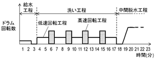
以上のように構成されたドラム式洗濯機について、以下、その動作、作用を説明する。図6A~6Cは、本発明の実施の形態1におけるドラム式洗濯機の回転槽内の洗濯物の状況を示す模式図である。図9A~9Cは、本発明の実施の形態1におけるドラム式洗濯機の洗濯工程の動作を示すタイムチャートである。
Hereinafter, the operation and action of the drum-type washing machine configured as described above will be described. 6A to 6C are schematic views showing the condition of the laundry in the rotary tub of the drum-type washing machine according to the first embodiment of the present invention. 9A to 9C are time charts showing the operation of the washing process of the drum-type washing machine according to the first embodiment of the present invention.
使用者が、扉体7を開いて回転槽4内に洗濯物を投入して運転を開始すると、制御部32は、投入された洗濯物の量を検知する。その後、給水弁15を開き、洗浄水が洗剤容器14内に貯蔵された洗濯洗剤を溶かして、洗浄水が給水経路16から水槽2内に給水される。
When the user opens the door 7 and puts the laundry into the rotary tub 4 to start the operation, the control unit 32 detects the amount of the loaded laundry. Thereafter, the water supply valve 15 is opened, the washing water dissolves the laundry detergent stored in the detergent container 14, and the washing water is supplied from the water supply path 16 into the water tank 2.
水槽2内に溜められる洗浄水は水位検知部(図示せず)によって検知される。洗濯物の量に応じて設定された水量の洗浄水が溜められると、制御部32は、給水を停止して洗濯を開始する。回転槽4はモータ9によって正逆回転駆動され、回転槽4内に収容された洗濯物は、回転槽4の円筒壁11に設けられた突起体12により回転方向に持ち上げられた後、落下し、洗濯物は叩き洗いの作用によって洗浄される。
The flush water stored in the water tank 2 is detected by a water level detector (not shown). When the washing water of the amount of water set according to the amount of the laundry is stored, the control unit 32 stops the water supply and starts the washing. The rotation tank 4 is driven to rotate in the forward and reverse directions by the motor 9, and the laundry stored in the rotation tank 4 is lifted in the rotation direction by the projections 12 provided on the cylindrical wall 11 of the rotation tank 4 and then dropped. , The laundry is washed by the action of tap washing.
洗浄水の水位は、叩き洗いの効果が得られるように洗濯物が洗浄水まで落下する距離で設定され、回転槽4内の下方まで洗浄水が溜められる。しかしながら、水槽2内の水位が低い状態では、洗濯物全体に洗浄水が行き渡りにくい。このため、回転槽4内の洗濯物に洗浄水を降りかけるべく、ポンプ21を動作させると、水槽2内の洗浄水は水槽2の底部に設けた排水口17から循環水路20内に引き込まれる。
The water level of the washing water is set by the distance at which the laundry falls to the washing water so that the effect of tapping and washing can be obtained, and the washing water is stored to the lower side in the rotary tank 4. However, when the water level in the water tank 2 is low, it is difficult for wash water to spread throughout the entire laundry. Therefore, when the pump 21 is operated to lower the washing water into the laundry in the rotation tank 4, the washing water in the water tank 2 is drawn into the circulating water channel 20 from the drainage port 17 provided at the bottom of the water tank 2. .
循環水路20から流入口25を通してノズル水路22へ送水された洗浄水は、環状に長く形成されたノズル水路22の端部22aに向かって2方向へ分岐され、等間隔に設けられた複数のノズル26(26a~26g)から回転槽4内に向かって拡散させながら噴出する。洗い時およびすすぎ時は、制御部32は、ポンプ21を動作させて水槽2内の洗浄水を循環させ、洗濯物に満遍なく洗浄水をかける。
The washing water supplied from the circulating water passage 20 to the nozzle water passage 22 through the inlet 25 is branched in two directions toward the end 22a of the nozzle water passage 22 formed in an annular shape, and the plurality of nozzles provided at equal intervals 26 (26a to 26g) and spouting while diffusing into the rotating tank 4; At the time of washing and rinsing, the control unit 32 operates the pump 21 to circulate the washing water in the water tank 2 and apply the washing water evenly to the laundry.
複数のノズル26(26a~26g)は、洗浄水の噴出方向Bを、回転槽4の開口面側から見て、回転槽4の回転軸心10に向けた方向から、同一方向へ所定の変位角度(ずらし角度)θ1で変位させるように構成されている。このため、ポンプ21により水槽2内に送水される洗浄水が、回転槽4内に噴出される範囲を均等に拡大することができる。これにより、回転槽4内で撹拌されて移動している洗濯物に対して洗浄水がかかる機会を多くでき、回転槽4内の洗濯物全体に満遍なく洗浄水を供給し続けることができる。
The plurality of nozzles 26 (26a to 26g) have predetermined displacement in the same direction from the direction toward the rotation axis 10 of the rotation tank 4 when the jet direction B of the washing water is viewed from the opening surface side of the rotation tank 4 It is configured to be displaced at an angle (displacement angle) θ1. For this reason, it is possible to evenly expand the range in which wash water supplied to the water tank 2 by the pump 21 is spouted into the rotating tank 4. As a result, it is possible to increase the opportunity for washing water to be applied to the laundry being agitated and moved in the rotary tank 4, and the washing water can be continuously supplied evenly to the entire laundry in the rotary tank 4.
また、複数のノズル26の少なくとも1個以上のノズル26gは、回転槽4の開口部6の周縁部23の上端近傍から回転槽4内に向かって洗浄水を噴出するように構成している。このため、洗濯物の最上点近傍から洗浄水をかけることができ、上方の洗濯物に供給された洗浄水が重力により下方へと流れていく。この過程において、洗浄水が下方の洗濯物にも供給されるため、効率よく洗濯物全体に満遍なく洗浄水を供給し続けることができる。
Further, at least one or more nozzles 26 g of the plurality of nozzles 26 are configured to eject the washing water from the vicinity of the upper end of the peripheral portion 23 of the opening 6 of the rotation tank 4 toward the inside of the rotation tank 4. For this reason, the washing water can be poured from the vicinity of the uppermost point of the laundry, and the washing water supplied to the upper laundry flows downward by gravity. In this process, since the washing water is also supplied to the lower laundry, the washing water can be efficiently and evenly supplied to the entire laundry.
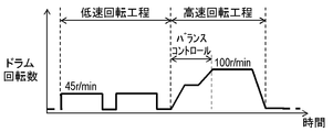
ドラム式洗濯機の洗い工程では、上述の叩き洗いの作用が主体である。叩き洗いは、回転槽4内の洗濯物が回転槽4の内周壁に張り付かない程度の速度、例えば45r/minで回転する第1の回転工程により実行される。しかし、洗濯物の量および汚れの種類等によっては、遠心力洗浄の作用が有効である。遠心力洗浄は、回転槽4内の洗濯物が回転槽4の内周壁に張り付く程度の速度、例えば100r/minで回転する第2の回転工程により実行される。第2の回転工程においては、遠心力により回転槽4内側から外側へ向けて洗浄水が汚れや洗剤分とともに移動する。
In the washing process of the drum type washing machine, the above-mentioned operation of tapping is the main. The tap washing is performed by a first rotation step of rotating at a speed such that the laundry in the rotation tank 4 does not stick to the inner peripheral wall of the rotation tank 4, for example, 45 r / min. However, depending on the amount of laundry and the type of dirt, the action of centrifugal cleaning is effective. Centrifugal cleaning is performed by a second rotation process in which the laundry in the rotation tank 4 is rotated at a speed such as 100 r / min, for example, to stick the inner peripheral wall of the rotation tank 4. In the second rotation step, the washing water moves from the inside to the outside of the rotation tank 4 together with the dirt and the detergent due to the centrifugal force.
即ち、図6Aに示すように、回転槽4内に多量の洗濯物を収容した場合、叩き洗いの作用が十分に得られない場合がある。特に回転槽4の中央部に位置する洗濯物は、常に中央部周辺で回転するだけでなく、洗浄水が行き渡りにくいため、十分な洗浄効果が得られない。つまり、洗濯物に付着した汚れが固形物ではなく、水溶性の汚れ等の場合、洗浄水が洗濯物の繊維を通過しさえすれば汚れが除去できるにも関わらず、上述の通りに洗浄水が行き渡らなければ、洗浄効果が期待できない。
That is, as shown in FIG. 6A, when a large amount of laundry is accommodated in the rotary tank 4, there may be a case where the function of tapping and washing can not be obtained sufficiently. In particular, the laundry located in the central portion of the rotation tank 4 not only rotates around the central portion constantly, but also the washing water hardly spreads, so a sufficient cleaning effect can not be obtained. That is, in the case where the dirt attached to the laundry is not a solid and is a water-soluble dirt, etc., although the dirt can be removed only if the washing water passes through the fibers of the laundry, the washing water as described above Can not be expected to have a cleaning effect.
そこで、本実施の形態においては、回転槽4内の洗濯物が回転槽4の内周壁に張り付く程度の速度で回転する第2の回転工程による、いわゆる遠心力洗浄が行われる。図6Bに示す通り、第2の回転工程を行うことで、遠心力により回転槽4内側から外側へ向けて洗浄水が汚れや洗剤分とともに、繊維を通過して移動していく。これにより、上述の回転槽4の中央部に位置する洗濯物に付着した水溶性汚れ等も効果的に除去できる。
Therefore, in the present embodiment, so-called centrifugal cleaning is performed by the second rotation process in which the laundry in the rotation tank 4 rotates at a speed such that the laundry sticks to the inner circumferential wall of the rotation tank 4. As shown in FIG. 6B, by performing the second rotation step, the washing water moves through the fiber together with the dirt and the detergent component from the inside to the outside of the rotation tank 4 by the centrifugal force. Thereby, the water-soluble dirt etc. which adhered to the laundry located in the central part of the above-mentioned rotation tank 4 can be removed effectively.
以上に示した第1の回転工程と第2の回転工程とが交互に繰り返されることで、回転槽4内の洗濯物の量や、洗濯物に付着した汚れの種類に関わらず、回転槽4内の洗濯物全体を効率的に洗浄することができる。
By alternately repeating the first rotation step and the second rotation step described above, the rotation tank 4 is selected regardless of the amount of laundry in the rotation tank 4 or the type of dirt attached to the laundry. The entire laundry can be efficiently cleaned.
しかしながら、第2の回転工程において、所望の遠心力洗浄の効果を得るには、複数回の第2の回転工程の実施が不可欠となる。即ち、図6B)に示す通り、一度、遠心力により回転槽4内側から外側へ向けて洗浄水が汚れや洗剤分とともに繊維を通過して移動した後は、そのまま運転継続しても、それ以上新たな洗浄水の移動は起こらない。つまり、再度、回転槽4内側の衣類に洗浄水を供給する必要があるので、第1の低速回転工程を実施し、その後に再度、第2の高速回転工程を行う必要がある。
However, in the second rotation step, in order to obtain the desired centrifugal cleaning effect, it is essential to carry out a plurality of second rotation steps. That is, as shown in FIG. 6B), once the washing water moves from the inside to the outside of the rotary tank 4 by the centrifugal force and passes through the fiber together with the dirt and the detergent component, even if the operation continues as it is There is no transfer of new wash water. That is, since it is necessary to supply wash water to the clothes inside the rotation tank 4 again, it is necessary to carry out the first low speed rotation step and then to carry out the second high speed rotation step again.
ところが、図9Aに示す通り、洗い工程中に第2の回転工程を頻繁に、例えば4、5回など行うと、弊害が生じる場合もある。例えば、回転槽4が水槽2に浸った状態で回転槽4を高速回転すると、回転槽4による水槽2内の洗浄水が、撹拌作用によって異常発泡するという懸念がある。
However, as shown in FIG. 9A, if the second rotation process is frequently performed, for example, four or five times during the washing process, adverse effects may occur. For example, when the rotary tank 4 is rotated at high speed in a state where the rotary tank 4 is immersed in the water tank 2, there is a concern that the cleaning water in the water tank 2 by the rotary tank 4 may abnormally foam due to the stirring action.
また、図9Bに示す通り、回転槽4を高速回転させる場合は、回転槽4のバランスを取る為のバランスコントロール工程が必要である。これら洗浄効果に寄与しないバランスコントロール工程を多い頻度で行うことは洗い時間を不要に延長することになる。
Further, as shown in FIG. 9B, when rotating the rotating tank 4 at a high speed, a balance control process for balancing the rotating tank 4 is required. The frequent execution of the balance control process which does not contribute to the washing effect unnecessarily extends the washing time.
そこで、洗い工程中に多い頻度で第2の回転工程を実施するのではなく、図6Cに示す通り、第2の回転工程において、ポンプ21を駆動し、循環水路20、ノズル水路22、複数のノズル26等を経て、水槽2内の洗浄水を回転槽4の内周壁に張り付いた洗濯物に常時供給させる。これにより、図9Cに示す通り、少ない頻度、例えば1、2回の第2の回転工程を実施する場合でも、ポンプ21を駆動せずに多い頻度で第2の高速回転工程を実施した場合と同等の遠心力洗浄の効果が得られる。また同時に、上述のような第2の回転工程において、回転槽4の撹拌作用による異常発泡や、バランスコントロール時間が増えることによる洗い時間の不要な延長を回避できる。
Therefore, the pump 21 is driven in the second rotation step as shown in FIG. 6C instead of performing the second rotation step frequently in the washing step, and the circulation water passage 20, the nozzle water passage 22, and the plurality of The washing water in the water tank 2 is constantly supplied to the laundry stuck to the inner peripheral wall of the rotation tank 4 through the nozzle 26 and the like. Thereby, as shown in FIG. 9C, even when the second rotation process is performed less frequently, for example, once or twice, the second high-speed rotation process is frequently performed without driving the pump 21. An equivalent centrifugal cleaning effect can be obtained. At the same time, it is possible to avoid abnormal foaming due to the stirring action of the rotary tank 4 and unnecessary prolongation of the washing time due to the increase of the balance control time in the second rotation step as described above.
また、第2の回転工程を1、2回としてポンプ21を駆動する場合、複数のノズル26により、回転槽4内の洗濯物全体に満遍なく洗浄水を供給しなければ、上述のような少ない頻度での高速回転工程による遠心力洗浄の効果は得られない。即ち、回転槽4の内周壁に張り付いた洗濯物の一部にでも洗浄水が供給されていなければ、その洗濯物に再度洗浄水を供給するために、第1の回転工程を実施する必要があるからである。ノズル26が複数設けられているので、ポンプ21により水槽2内に送水された洗浄水が、ノズル26近傍の一部の洗濯物へだけでなく、回転槽4内の内周壁に張り付いた洗濯物全体に満遍なく供給し続けることができる。以下、詳細に説明する。
In addition, when the pump 21 is driven with the second rotation process once or twice, if the washing water is not evenly supplied to the entire laundry in the rotating tank 4 by the plurality of nozzles 26, the frequency as described above is low. The effect of the centrifugal washing by the high speed rotation process in the above can not be obtained. That is, if the washing water is not supplied to even part of the laundry stuck to the inner peripheral wall of the rotation tank 4, it is necessary to carry out the first rotation step to again supply the washing water to the laundry. Because there is Since a plurality of nozzles 26 are provided, the washing water supplied to the water tank 2 by the pump 21 is not only attached to a part of the laundry near the nozzles 26 but also attached to the inner circumferential wall in the rotating tank 4 We can continue to supply the whole thing evenly. The details will be described below.
図7は、1箇所のノズルから循環水の噴射を行う場合の洗濯物の状況を示す模式図である。図8は、本発明の実施の形態1におけるドラム式洗濯機の複数のノズルから循環水の噴射を行う場合の洗濯物の状況を示す模式図である。
FIG. 7: is a schematic diagram which shows the condition of the laundry in the case of injecting circulating water from one nozzle. FIG. 8 is a schematic view showing the state of the laundry in the case where the circulating water is sprayed from the plurality of nozzles of the drum-type washing machine in the first embodiment of the present invention.
図7に示す通り、一箇所のノズルaから回転槽4内の洗濯物A~Gに洗浄水を供給する場合、回転槽4が1回転する間に、各洗濯物A~Gにはそれぞれ1回しか洗浄水が供給されず十分な洗浄が行われない。よって、所望の洗浄効果を得るには、長時間、第2の回転工程を実施する必要があり、工程時間の長期化や消費電力の浪費が避けられない。
As shown in FIG. 7, when washing water is supplied to the laundry items A to G in the rotary tank 4 from one nozzle a, each laundry item 1 to G has 1 each while the rotary tank 4 makes one rotation. Washing water is supplied only once and sufficient washing is not performed. Therefore, in order to obtain a desired cleaning effect, it is necessary to carry out the second rotation step for a long time, and it is inevitable to prolong the process time and waste power consumption.
そこで、第2の回転工程において、ポンプ21を駆動し、循環水路20、ノズル水路22、複数のノズル26等を経て、水槽2内の洗浄水を回転槽4の内周壁に張り付いた洗濯物全体に満遍なく常時供給させる。これにより、上述の課題が回避できる。即ち、図8に示す通り、複数のノズル、例えばノズルa~gの7箇所から、回転槽4内の洗濯物A~Gに洗浄水を供給する場合、回転槽4が1回転する間に、各洗濯物A~Gにはそれぞれ7回、洗浄水の供給が繰り返して行われる。つまり、ノズル26が1箇所の場合に比べて同じ時間で7倍の洗浄水の供給が行われるので、7倍の洗浄効果が得られる。この結果、工程時間を1/7にしても同等の効果を発揮する為、工程時間の短縮化や消費電力の低減が可能となる。
Therefore, in the second rotation step, the pump 21 is driven, and the washing water in the water tank 2 is attached to the inner peripheral wall of the rotating tank 4 through the circulating water channel 20, the nozzle water channel 22, the plurality of nozzles 26 and the like. Always supply the whole evenly. Thereby, the above-mentioned subject can be avoided. That is, as shown in FIG. 8, when washing water is supplied from a plurality of nozzles, for example, seven locations of the nozzles a to g to the laundry items A to G in the rotary tank 4, the rotary tank 4 makes one revolution while Each of the laundry items A to G is repeatedly supplied with washing water seven times. That is, since the supply of cleaning water seven times is performed in the same time as in the case where one nozzle 26 is provided, the cleaning effect seven times can be obtained. As a result, even if the process time is 1/7, the same effect can be obtained, so that the process time can be shortened and the power consumption can be reduced.
一方、使用者が水槽2内の水位を設定する水位設定部(図示せず)により、水槽2内の水位を所定水位より高く設定した場合は、制御部32は第2の回転工程を行わないこととする。回転槽4内に多量の洗濯物を収容していた場合でも、回転槽4の中央部に位置する洗濯物に洗浄水が行き渡っていれば、即ち、洗浄水に浸っていれば、第1の回転工程のみでも洗浄効果が期待できるためである。更に、水槽2内の水位が高い場合は、上述の回転槽4が水槽2内の洗浄水を撹拌することで起こる異常発泡がより顕著となる懸念もある。このため、水槽2内の水位が所定水位よりも高い場合には、制御部32は、第2の回転工程を行わないようにする方が好ましい。
On the other hand, when the user sets the water level in the water tank 2 higher than the predetermined water level by the water level setting unit (not shown) that sets the water level in the water tank 2, the control unit 32 does not perform the second rotation process. To be. Even if a large amount of laundry is accommodated in the rotary tank 4, if the washing water is widespread in the laundry located at the central portion of the rotary tank 4, that is, if it is immersed in the washing water, the first This is because the cleaning effect can be expected only by the rotation process. Furthermore, when the water level in the water tank 2 is high, there is a concern that the abnormal foaming that occurs when the above-mentioned rotary tank 4 stirs the washing water in the water tank 2 becomes more remarkable. For this reason, when the water level in the water tank 2 is higher than the predetermined water level, the control unit 32 preferably does not perform the second rotation process.
所定の洗い時間が経過すると、制御部32は排水弁19を開いて水槽2内の洗浄水を、排水経路18を通して排水する。排水終了後、新たにすすぎ用のすすぎ水を給水して、すすぎ工程を実行する。すすぎ工程における回転槽4の動作は、洗い工程と同様である。すすぎ工程でも洗い工程と同様に、第1の回転工程および第2の回転工程を実施することで、回転槽4内の洗濯物の量等に関わらず、効果的にすすぎを行うことができる。
When the predetermined washing time has elapsed, the control unit 32 opens the drain valve 19 to drain the washing water in the water tank 2 through the drain passage 18. After the drainage is completed, rinse water for rinsing is newly supplied to carry out the rinsing step. The operation of the rotary tank 4 in the rinsing step is the same as the washing step. By performing the first rotation step and the second rotation step in the same manner as the washing step in the rinsing step, it is possible to effectively perform the rinsing regardless of the amount of the laundry in the rotation tank 4 or the like.
所定回数のすすぎ工程が終わると、制御部32は、排水弁19を開いて水槽2内のすすぎ水を排水する。その後、回転槽4を高速回転させて洗濯物に含まれているすすぎ水を脱水する、脱水工程を所定時間実行して運転を終了する。もしくは、乾燥装置を設け、脱水工程に続いて乾燥工程を実行するようにしてもよい。
After the predetermined number of rinse steps, the controller 32 opens the drain valve 19 to drain the rinse water in the water tank 2. Thereafter, the rotary tank 4 is rotated at a high speed to dewater the rinse water contained in the laundry. A dewatering process is performed for a predetermined time to complete the operation. Alternatively, a drying device may be provided and the drying step may be performed following the dewatering step.
以上のように、本実施の形態のドラム式洗濯機は、回転槽4の開口部6の周縁部複数箇所から洗浄水を噴出して回転槽4内の洗濯物に満遍なく洗浄水を供給することができる。回転槽4内の洗濯物が回転槽4の内周壁に張り付く程度の速度で回転する工程において、上述の洗浄水を噴出することで、洗浄効率を高めることができる。
As described above, in the drum-type washing machine according to the present embodiment, the washing water is spouted from a plurality of peripheral portions of the opening 6 of the rotation tank 4 to evenly supply the washing water to the laundry in the rotation tank 4 Can. In the step of rotating the laundry in the rotation tank 4 at a speed such that the laundry sticks to the inner peripheral wall of the rotation tank 4, the washing efficiency can be enhanced by spouting the above-described washing water.
以上説明したように、本発明のドラム式洗濯機は、洗浄水を溜める水槽と、水槽内に回転可能に配設され前面側に開口部を設けた回転槽と、回転槽を駆動するモータと、水槽内の洗浄水を回転槽へ循環させる循環水路と、水槽内の洗浄水を循環水路に送水するポンプと、循環水路と連通し、回転槽の開口部の周縁部の外側に略円状に設けられたノズル水路と、ポンプによって送水される洗浄水を回転槽の内部に向けて噴出するようにノズル水路に設けられた複数のノズルと、モータとポンプを駆動して、洗い工程を行う制御部と、を備える。洗い工程は、回転槽内の洗濯物が回転槽の内周壁に張り付かない程度の速度で回転する第1の回転工程と、回転槽内の洗濯物が回転槽の内周壁に張り付く程度の速度で回転する第2の回転工程とを有する。制御部は、第2の回転工程において、ポンプを駆動して、回転槽の内周壁に張り付いた洗濯物に洗浄水を供給する。
As described above, the drum-type washing machine of the present invention includes a water tank for storing washing water, a rotary tank rotatably disposed in the water tank and provided with an opening on the front side, and a motor for driving the rotary tank. A circulating water channel for circulating washing water in the water tank to the rotation tank, a pump for feeding washing water in the water tank to the circulation water channel, and the circulation water channel, and the outer periphery of the opening of the rotation tank is substantially circular And a plurality of nozzles provided in the nozzle channel so as to eject the washing water supplied by the pump toward the inside of the rotary tank, the motor and the pump are driven to perform the washing step. And a control unit. The washing step includes a first rotation step in which the laundry in the rotation tank rotates at a speed not to stick to the inner peripheral wall of the rotation tank, and a speed at which the laundry in the rotation tank sticks to the inner peripheral wall of the rotation tank And a second rotation step of rotating. In the second rotation step, the control unit drives the pump to supply wash water to the laundry stuck to the inner peripheral wall of the rotation tank.
このような構成により、ポンプにより水槽内に送水された洗浄水が、噴出口近傍の一部の洗濯物へだけでなく、回転槽内の内周壁に張り付いた洗濯物全体に満遍なく供給し続けることができる。ここで、第2の回転工程中においては、遠心力により回転槽内側の洗濯物から回転槽外側の洗濯物へ向けて洗浄水が汚れや洗剤分とともに移動するいわゆる遠心力洗浄の効果が得られる。よって、ポンプにより常時、洗浄水を供給することで、遠心力による洗浄水の脱水と、循環水(洗浄水)がかけられることによる吸水とが繰り返されることとなり、遠心力洗浄の効果がより促進される。この結果、洗浄性能を向上させることができる。
With such a configuration, the washing water supplied into the water tank by the pump continues to be supplied uniformly not only to a part of the laundry in the vicinity of the spout but also to the entire laundry stuck to the inner peripheral wall in the rotating tank. be able to. Here, during the second rotation step, the effect of so-called centrifugal cleaning is obtained, in which the washing water moves with dirt and detergent from the laundry inside the rotary tank toward the laundry outside the rotary tank by centrifugal force. . Therefore, by always supplying the washing water by the pump, the dewatering of the washing water by the centrifugal force and the water absorption by the circulation water (washing water) being applied are repeated, and the effect of the centrifugal washing is further promoted. Be done. As a result, the cleaning performance can be improved.
また本発明のドラム式洗濯機では、水槽内の水位を設定する水位設定部を更に備える。制御部は、水位設定部により水槽内の水位が所定より高く設定された場合、第2の回転工程を行わない。
The drum type washing machine of the present invention further includes a water level setting unit for setting the water level in the water tank. The control unit does not perform the second rotation process when the water level in the water tank is set higher than a predetermined level by the water level setting unit.
このような構成により、水槽内の水位が高く第1の回転工程でも洗濯物が十分に洗浄水に浸る場合に、無用な工程を省略することができる。また、水槽内の水位が高い場合に第2の回転工程を行うと、回転による水槽内の洗浄水の撹拌作用によって異常発泡する場合がある為、この様な不具合の発生リスクを抑えることができる。
With such a configuration, when the water level in the water tank is high and the laundry is sufficiently immersed in the washing water even in the first rotation step, the unnecessary step can be omitted. Also, if the second rotation step is performed when the water level in the water tank is high, abnormal foaming may occur due to the stirring action of the washing water in the water tank due to the rotation, so the risk of occurrence of such problems can be suppressed. .
また本発明のドラム式洗濯機では、ノズルと開口部の周縁部との間の空間部にはノズルから空間部に噴出した洗浄水を開口部に向かって反射させるための反射部が設けられる。反射部は洗浄水の噴射方向に対して傾斜させた衝突面と、衝突面に衝突した噴流を回転槽内に導くために内周縁に設けた案内部を有する。
Further, in the drum-type washing machine of the present invention, a reflective portion for reflecting the washing water spouted from the nozzle to the space portion toward the opening portion is provided in the space portion between the nozzle and the peripheral portion of the opening portion. The reflecting portion has an impact surface inclined with respect to the jet direction of the washing water, and a guide portion provided on the inner peripheral edge to guide the jet flow which has collided with the impact surface into the rotating tank.
このような構成により、ノズルからの噴流を衝突面により回転槽内に直接導く必要がないため、衝突面の傾斜をノズルからの噴流方向に対して緩やかに設定することができる。そのため、ノズルからの噴流をより安定的に衝突面に着水させ、拡散させることができる。その後、案内部により噴流を回転槽内に向けた方向へ導くため、回転槽内の洗濯物に対して、安定した拡散状態で洗浄水を供給することができる。
With such a configuration, since it is not necessary to directly guide the jet from the nozzle into the rotary tank by the collision surface, the inclination of the collision surface can be set gently with respect to the direction of the jet from the nozzle. Therefore, the jet stream from the nozzle can be more stably landed on the collision surface and diffused. Thereafter, the guide portion guides the jet flow in the direction toward the inside of the rotary tank, so that washing water can be supplied to the laundry in the rotary tank in a stable diffusion state.
また本発明のドラム式洗濯機では、衝突面の洗浄水の噴射方向に対する傾斜角度を案内部の洗浄水の噴射方向に対する傾斜角度よりも緩やかに設定した。また、案内部で洗浄水を導く長さを衝突面で洗浄水を導く長さよりも短く設定した。
Further, in the drum type washing machine of the present invention, the inclination angle of the collision surface with respect to the jet direction of the washing water is set to be gentler than the inclination angle of the guide with respect to the jet direction of the washing water. Further, the length for guiding the washing water in the guide portion is set shorter than the length for guiding the washing water on the collision surface.
このような構成により、案内部における噴流の流速低下を最低限に抑えることができ、回転槽内の洗濯物に対して洗浄水をより勢いよく供給することができ、洗浄性能およびすすぎ性能を向上させることができる。
With such a configuration, it is possible to minimize the decrease in the flow velocity of the jet in the guide portion, and it is possible to supply the washing water more vigorously to the laundry in the rotary tank, and improve the washing performance and the rinse performance. It can be done.
また本発明のドラム式洗濯機では、ノズル水路の一部を回転槽の回転軸心側へ膨らませた膨出部を有する。膨出部の平面部に円形のノズル孔が設けられる。ノズル孔の貫通方向は平面部と略垂直であり、ノズル孔の長さがノズル孔の直径以下である。
Moreover, in the drum type washing machine of this invention, it has a bulging part which expanded a part of nozzle channel to the rotating shaft center side of a rotating tank. A circular nozzle hole is provided in a flat portion of the bulging portion. The penetration direction of the nozzle hole is substantially perpendicular to the flat portion, and the length of the nozzle hole is equal to or less than the diameter of the nozzle hole.
このような構成により、ノズルから噴出する噴流の乱れを抑えることができ、噴出される洗浄水の方向を安定させることができる。また、このノズルからの噴流を縮流させることができるため、噴流の流速を速め、噴出される洗浄水の勢いを強めることができる。
With such a configuration, the disturbance of the jet flow ejected from the nozzle can be suppressed, and the direction of the flush water to be ejected can be stabilized. In addition, since the jet flow from the nozzle can be contracted, the flow velocity of the jet can be increased, and the force of the jetted washing water can be strengthened.
また本発明のドラム式洗濯機では、ノズル孔の貫通方向は、回転槽の回転軸心に向けた方向から所定の変位角度だけ変位させた方向である。
Further, in the drum-type washing machine of the present invention, the penetration direction of the nozzle holes is a direction displaced by a predetermined displacement angle from the direction toward the rotation axis of the rotation tank.
このような構成により、回転槽内に噴出した洗浄水が通過する範囲を拡大することができ、回転槽内の洗濯物に洗浄水を効率よく満遍なく供給し続けることができる。
With such a configuration, it is possible to expand the range through which the wash water spouted into the rotary tank passes, and it is possible to efficiently and evenly supply the wash water to the laundry in the rotary tank.
以上のように、本発明にかかるドラム式洗濯機は、回転槽内の洗濯物の量に関わらず、洗濯物全体に満遍なく洗濯水を供給することができ、洗浄効率およびすすぎ効率を高めることができるので、ドラム式洗濯機として有用である。
As described above, the drum-type washing machine according to the present invention can uniformly supply the washing water to the entire laundry regardless of the amount of laundry in the rotating tank, and can improve the washing efficiency and the rinse efficiency. Because it can, it is useful as a drum type washing machine.
1 筐体
2 水槽
4 回転槽
5,6 開口部
7 扉体
8 ベローズ
9 モータ
10 回転軸心
11 円筒壁
12 突起体
13 小孔
14 洗剤容器
15 給水弁
16 給水経路
17 排水口
18 排水経路
19 排水弁
20 循環水路
21 ポンプ
22,102 ノズル水路
22b,103 内壁面
23 周縁部
24 内周縁部
25 流入口
26,26a,26b,26c,26d,26e,26f,26g,100 ノズル
27 空間部
28 反射部
28a 衝突面
28b 案内部
29 膨出部
30 平面部
31,101 ノズル孔
32 制御部 DESCRIPTION OFSYMBOLS 1 case 2 water tank 4 rotation tank 5, 6 opening part 7 door 8 bellows 9 motor 10 rotation axis 11 cylindrical wall 12 protrusion 13 small hole 14 detergent container 15 water supply valve 16 water supply path 17 drainage port 18 drainage path 19 drainage Valve 20 circulating water channel 21 pump 22, 102 nozzle water channel 22b, 103 inner wall surface 23 peripheral edge portion 24 inner peripheral edge portion 25 inlet port 26, 26a, 26b, 26c, 26d, 26e, 26f, 26g, 100 nozzle 27 space portion 28 reflection portion 28a collision surface 28b guide portion 29 bulging portion 30 flat portion 31, 101 nozzle hole 32 control portion
2 水槽
4 回転槽
5,6 開口部
7 扉体
8 ベローズ
9 モータ
10 回転軸心
11 円筒壁
12 突起体
13 小孔
14 洗剤容器
15 給水弁
16 給水経路
17 排水口
18 排水経路
19 排水弁
20 循環水路
21 ポンプ
22,102 ノズル水路
22b,103 内壁面
23 周縁部
24 内周縁部
25 流入口
26,26a,26b,26c,26d,26e,26f,26g,100 ノズル
27 空間部
28 反射部
28a 衝突面
28b 案内部
29 膨出部
30 平面部
31,101 ノズル孔
32 制御部 DESCRIPTION OF
Claims (6)
- 洗浄水を溜める水槽と、
前記水槽内に回転可能に配設され前面側に開口部を設けた回転槽と、
前記回転槽を駆動するモータと、
前記水槽内の洗浄水を前記回転槽へ循環させる循環水路と、
前記水槽内の洗浄水を前記循環水路に送水するポンプと、
前記循環水路と連通し、前記回転槽の開口部の周縁部の外側に略円状に設けられたノズル水路と、
前記ポンプによって送水される洗浄水を前記回転槽の内部に向けて噴出するように前記ノズル水路に設けられた複数のノズルと、
前記モータと前記ポンプを駆動して、洗い工程を行う制御部とを備え、
前記洗い工程は、前記回転槽内の洗濯物が前記回転槽の内周壁に張り付かない程度の速度で回転する第1の回転工程と、前記回転槽内の洗濯物が前記回転槽の内周壁に張り付く程度の速度で回転する第2の回転工程とを有し、
前記制御部は、前記第2の回転工程において、前記ポンプを駆動して、前記回転槽の内周壁に張り付いた前記洗濯物に前記洗浄水を供給するようにしたことを特徴とするドラム式洗濯機。 And a water tank for storing washing water,
A rotary tank rotatably disposed in the water tank and having an opening on the front side;
A motor for driving the rotating tank;
A circulation channel for circulating wash water in the water tank to the rotary tank;
A pump for supplying wash water in the water tank to the circulation channel;
A nozzle water passage communicating with the circulating water passage and provided in a substantially circular shape on the outer side of the peripheral portion of the opening of the rotary tank;
A plurality of nozzles provided in the nozzle channel so as to eject cleaning water supplied by the pump toward the inside of the rotary tank;
And a controller for driving the motor and the pump to perform a washing process.
The washing step is a first rotation step in which the laundry in the rotary tub is rotated at a speed not to stick to the inner peripheral wall of the rotary tub, and the laundry in the rotary tub is the inner peripheral wall of the rotary tub And a second rotation step rotating at a speed enough to stick to the
The control unit is configured to drive the pump to supply the washing water to the laundry stuck to the inner peripheral wall of the rotary tank in the second rotation step. Washing machine. - 前記水槽内の水位を設定する水位設定部を更に備え、
前記制御部は、前記水位設定部により前記水槽内の水位が所定より高く設定された場合、前記第2の回転工程を行わないことを特徴とする請求項1記載のドラム式洗濯機。 It further comprises a water level setting unit for setting the water level in the water tank,
The drum type washing machine according to claim 1, wherein the control unit does not perform the second rotation process when the water level in the water tank is set higher than a predetermined level by the water level setting unit. - 前記ノズルと前記開口部の周縁部との間の空間部には前記ノズルから前記空間部に噴出した洗浄水を前記開口部に向かって反射させるための反射部が設けられ、
前記反射部は洗浄水の噴射方向に対して傾斜させた衝突面と、前記衝突面に衝突した噴流を前記回転槽内に導くために内周縁に設けた案内部を有することを特徴とする請求項1記載のドラム式洗濯機。 The space between the nozzle and the peripheral edge of the opening is provided with a reflecting portion for reflecting the washing water spouted from the nozzle to the space toward the opening.
The reflecting portion has a collision surface inclined with respect to the jet direction of the washing water, and a guiding portion provided on the inner peripheral edge to guide the jet flow colliding with the collision surface into the rotary tank. The drum-type washing machine according to Item 1. - 前記衝突面の洗浄水の噴射方向に対する傾斜角度を前記案内部の洗浄水の噴射方向に対する傾斜角度よりも緩やかに設定し、前記案内部で洗浄水を導く長さを前記衝突面で洗浄水を導く長さよりも短く設定したことを特徴とする請求項3記載のドラム式洗濯機。 The inclination angle of the collision surface to the jetting direction of the washing water is set more gently than the inclination angle of the guiding portion to the jetting direction of the washing water, and the guiding portion guides the washing water at the collision surface. The drum type washing machine according to claim 3, characterized in that the length is set shorter than the lead length.
- 前記ノズル水路の一部を前記回転槽の回転軸心側へ膨らませた膨出部を有し、前記膨出部の平面部に円形のノズル孔が設けられ、前記ノズル孔の貫通方向は前記平面部と略垂直であり、前記ノズル孔の長さが前記ノズル孔の直径以下であることを特徴とする請求項1記載のドラム式洗濯機。 It has a bulging portion obtained by bulging a part of the nozzle channel toward the rotational axis of the rotary tank, and a circular nozzle hole is provided in a flat portion of the bulging portion, and the penetration direction of the nozzle hole is the flat The drum type washing machine according to claim 1, which is substantially perpendicular to a portion, and a length of the nozzle hole is equal to or less than a diameter of the nozzle hole.
- 前記ノズル孔の貫通方向は、前記回転槽の回転軸心に向けた方向から所定の変位角度だけ変位させた方向であることを特徴とする請求項5記載のドラム式洗濯機。 The drum-type washing machine according to claim 5, wherein the penetration direction of the nozzle hole is a direction displaced from the direction toward the rotation axis of the rotation tank by a predetermined displacement angle.
Priority Applications (2)
| Application Number | Priority Date | Filing Date | Title |
|---|---|---|---|
| EP12830481.3A EP2754744B1 (en) | 2011-09-05 | 2012-08-30 | Drum-type washing machine |
| CN201280031346.7A CN103620105B (en) | 2011-09-05 | 2012-08-30 | Tumbling-box washing machine |
Applications Claiming Priority (2)
| Application Number | Priority Date | Filing Date | Title |
|---|---|---|---|
| JP2011-192678 | 2011-09-05 | ||
| JP2011192678A JP5919488B2 (en) | 2011-09-05 | 2011-09-05 | Drum washing machine |
Publications (1)
| Publication Number | Publication Date |
|---|---|
| WO2013035277A1 true WO2013035277A1 (en) | 2013-03-14 |
Family
ID=47831752
Family Applications (1)
| Application Number | Title | Priority Date | Filing Date |
|---|---|---|---|
| PCT/JP2012/005477 WO2013035277A1 (en) | 2011-09-05 | 2012-08-30 | Drum-type washing machine |
Country Status (4)
| Country | Link |
|---|---|
| EP (1) | EP2754744B1 (en) |
| JP (1) | JP5919488B2 (en) |
| CN (1) | CN103620105B (en) |
| WO (1) | WO2013035277A1 (en) |
Families Citing this family (6)
| Publication number | Priority date | Publication date | Assignee | Title |
|---|---|---|---|---|
| DE102015214803A1 (en) * | 2015-08-04 | 2017-02-09 | BSH Hausgeräte GmbH | Laundry care device with a circulation system |
| DE102016206047A1 (en) * | 2016-04-12 | 2017-10-12 | BSH Hausgeräte GmbH | Laundry care device with a controller |
| EP3933090A1 (en) | 2017-12-28 | 2022-01-05 | LG Electronics Inc. | Washing machine having a circulation pump |
| EP3505668B1 (en) | 2017-12-28 | 2021-06-09 | LG Electronics Inc. | Method for controlling washing machine |
| CN110387699B (en) * | 2018-04-16 | 2021-10-29 | 青岛海尔洗涤电器有限公司 | Roller washing machine and spraying system thereof |
| JP2021519192A (en) * | 2018-04-16 | 2021-08-10 | チンタオ・ハイアール・ドラム・ウォッシング・マシーン・カンパニー・リミテッド | Drum washing machine and its spray system |
Citations (8)
| Publication number | Priority date | Publication date | Assignee | Title |
|---|---|---|---|---|
| JPH10127978A (en) | 1996-10-30 | 1998-05-19 | Sharp Corp | Drum type washing machine |
| JPH10235069A (en) * | 1997-02-21 | 1998-09-08 | Matsushita Electric Ind Co Ltd | Washing machine |
| JP2007111410A (en) * | 2005-10-24 | 2007-05-10 | Matsushita Electric Ind Co Ltd | Drum type washer/dryer |
| JP2011045517A (en) * | 2009-08-27 | 2011-03-10 | Panasonic Corp | Drum type washing machine |
| JP2011045516A (en) * | 2009-08-27 | 2011-03-10 | Panasonic Corp | Drum type washing machine |
| JP2011055923A (en) * | 2009-09-08 | 2011-03-24 | Panasonic Corp | Drum type washing machine |
| JP2011509139A (en) * | 2008-04-08 | 2011-03-24 | エルジー エレクトロニクス インコーポレイティド | Washing machine |
| JP2011245268A (en) * | 2010-04-26 | 2011-12-08 | Toshiba Corp | Drum-type washing machine |
Family Cites Families (6)
| Publication number | Priority date | Publication date | Assignee | Title |
|---|---|---|---|---|
| JP4972369B2 (en) * | 2006-09-20 | 2012-07-11 | 日立アプライアンス株式会社 | Drum washing machine |
| JP4325736B1 (en) * | 2008-04-28 | 2009-09-02 | パナソニック株式会社 | Drum washing machine |
| US9695537B2 (en) * | 2009-07-27 | 2017-07-04 | Lg Electronics Inc. | Control method of a laundry machine |
| TW201114972A (en) * | 2009-09-09 | 2011-05-01 | Panasonic Corp | Drum type washing machine |
| EP2516718B1 (en) * | 2009-12-23 | 2016-05-04 | LG Electronics Inc. | Washing method and washing machine |
| EP2343409B1 (en) * | 2010-01-08 | 2014-02-12 | Panasonic Corporation | Washing machine |
-
2011
- 2011-09-05 JP JP2011192678A patent/JP5919488B2/en active Active
-
2012
- 2012-08-30 WO PCT/JP2012/005477 patent/WO2013035277A1/en active Application Filing
- 2012-08-30 CN CN201280031346.7A patent/CN103620105B/en active Active
- 2012-08-30 EP EP12830481.3A patent/EP2754744B1/en active Active
Patent Citations (8)
| Publication number | Priority date | Publication date | Assignee | Title |
|---|---|---|---|---|
| JPH10127978A (en) | 1996-10-30 | 1998-05-19 | Sharp Corp | Drum type washing machine |
| JPH10235069A (en) * | 1997-02-21 | 1998-09-08 | Matsushita Electric Ind Co Ltd | Washing machine |
| JP2007111410A (en) * | 2005-10-24 | 2007-05-10 | Matsushita Electric Ind Co Ltd | Drum type washer/dryer |
| JP2011509139A (en) * | 2008-04-08 | 2011-03-24 | エルジー エレクトロニクス インコーポレイティド | Washing machine |
| JP2011045517A (en) * | 2009-08-27 | 2011-03-10 | Panasonic Corp | Drum type washing machine |
| JP2011045516A (en) * | 2009-08-27 | 2011-03-10 | Panasonic Corp | Drum type washing machine |
| JP2011055923A (en) * | 2009-09-08 | 2011-03-24 | Panasonic Corp | Drum type washing machine |
| JP2011245268A (en) * | 2010-04-26 | 2011-12-08 | Toshiba Corp | Drum-type washing machine |
Non-Patent Citations (1)
| Title |
|---|
| See also references of EP2754744A4 * |
Also Published As
| Publication number | Publication date |
|---|---|
| CN103620105A (en) | 2014-03-05 |
| EP2754744B1 (en) | 2016-11-16 |
| EP2754744A1 (en) | 2014-07-16 |
| CN103620105B (en) | 2016-07-06 |
| JP5919488B2 (en) | 2016-05-18 |
| JP2013052123A (en) | 2013-03-21 |
| EP2754744A4 (en) | 2015-01-21 |
Similar Documents
| Publication | Publication Date | Title |
|---|---|---|
| WO2013035278A1 (en) | Drum-type washing machine | |
| WO2013035277A1 (en) | Drum-type washing machine | |
| KR20120071528A (en) | Washing machine | |
| KR100785555B1 (en) | Drum type washing machine | |
| JP5423585B2 (en) | Drum washing machine | |
| AU2007338916B2 (en) | Improved water saving washing machine | |
| JP2014045932A (en) | Drum type washing machine | |
| JP5560911B2 (en) | Drum washing machine | |
| JPH10235064A (en) | Washing machine with turbulence generating device | |
| JP5671687B2 (en) | Drum washing machine | |
| KR20000010506A (en) | Pulsator of washing machine | |
| JP2014097091A (en) | Drum type washing machine | |
| JP5945737B2 (en) | Drum washing machine | |
| KR100238657B1 (en) | Pulsator of a washing machine | |
| KR100271166B1 (en) | A pulsator of washing machine | |
| KR100238658B1 (en) | Pulsator of a washing machine | |
| JP2012065866A (en) | Washing machine | |
| JP2014068738A (en) | Drum type washing machine | |
| KR100352473B1 (en) | Side stream blower of washing machine_ | |
| KR19990021443U (en) | Pulsator in washing machine | |
| KR19990043525A (en) | Pulsator in washing machine | |
| KR19990021441U (en) | Pulsator in washing machine | |
| KR19990021442U (en) | Pulsator in washing machine | |
| KR100218286B1 (en) | A pulsator of washing machine | |
| JP2012055403A (en) | Washing machine |
Legal Events
| Date | Code | Title | Description |
|---|---|---|---|
| 121 | Ep: the epo has been informed by wipo that ep was designated in this application |
Ref document number: 12830481 Country of ref document: EP Kind code of ref document: A1 |
|
| REEP | Request for entry into the european phase |
Ref document number: 2012830481 Country of ref document: EP |
|
| WWE | Wipo information: entry into national phase |
Ref document number: 2012830481 Country of ref document: EP |
|
| NENP | Non-entry into the national phase |
Ref country code: DE |