EP1679129A2 - Pistole zum Auftragen von Heissschmelzklebern - Google Patents
Pistole zum Auftragen von Heissschmelzklebern Download PDFInfo
- Publication number
- EP1679129A2 EP1679129A2 EP06007455A EP06007455A EP1679129A2 EP 1679129 A2 EP1679129 A2 EP 1679129A2 EP 06007455 A EP06007455 A EP 06007455A EP 06007455 A EP06007455 A EP 06007455A EP 1679129 A2 EP1679129 A2 EP 1679129A2
- Authority
- EP
- European Patent Office
- Prior art keywords
- gun
- applicator gun
- housing
- applicator
- hydraulic material
- Prior art date
- Legal status (The legal status is an assumption and is not a legal conclusion. Google has not performed a legal analysis and makes no representation as to the accuracy of the status listed.)
- Withdrawn
Links
- 239000004831 Hot glue Substances 0.000 title abstract description 36
- 239000000463 material Substances 0.000 claims abstract description 50
- 238000001514 detection method Methods 0.000 claims description 4
- 238000010438 heat treatment Methods 0.000 claims description 2
- 230000007246 mechanism Effects 0.000 abstract description 29
- 230000013011 mating Effects 0.000 description 39
- 239000000853 adhesive Substances 0.000 description 29
- 230000001070 adhesive effect Effects 0.000 description 29
- 239000000945 filler Substances 0.000 description 9
- 230000000694 effects Effects 0.000 description 7
- 210000005069 ears Anatomy 0.000 description 5
- 238000004519 manufacturing process Methods 0.000 description 5
- 238000012856 packing Methods 0.000 description 4
- 239000012530 fluid Substances 0.000 description 2
- 238000012423 maintenance Methods 0.000 description 2
- 230000002093 peripheral effect Effects 0.000 description 2
- 239000007787 solid Substances 0.000 description 2
- 230000004075 alteration Effects 0.000 description 1
- 230000000712 assembly Effects 0.000 description 1
- 238000000429 assembly Methods 0.000 description 1
- 238000006243 chemical reaction Methods 0.000 description 1
- 230000001419 dependent effect Effects 0.000 description 1
- 238000012986 modification Methods 0.000 description 1
- 230000004048 modification Effects 0.000 description 1
- 230000003449 preventive effect Effects 0.000 description 1
- 238000007789 sealing Methods 0.000 description 1
- 230000003068 static effect Effects 0.000 description 1
- 238000006467 substitution reaction Methods 0.000 description 1
Images


Classifications
-
- B—PERFORMING OPERATIONS; TRANSPORTING
- B05—SPRAYING OR ATOMISING IN GENERAL; APPLYING FLUENT MATERIALS TO SURFACES, IN GENERAL
- B05B—SPRAYING APPARATUS; ATOMISING APPARATUS; NOZZLES
- B05B12/00—Arrangements for controlling delivery; Arrangements for controlling the spray area
- B05B12/002—Manually-actuated controlling means, e.g. push buttons, levers or triggers
- B05B12/0022—Manually-actuated controlling means, e.g. push buttons, levers or triggers associated with means for restricting their movement
- B05B12/0024—Manually-actuated controlling means, e.g. push buttons, levers or triggers associated with means for restricting their movement to a single position
- B05B12/0026—Manually-actuated controlling means, e.g. push buttons, levers or triggers associated with means for restricting their movement to a single position to inhibit delivery
-
- B—PERFORMING OPERATIONS; TRANSPORTING
- B05—SPRAYING OR ATOMISING IN GENERAL; APPLYING FLUENT MATERIALS TO SURFACES, IN GENERAL
- B05B—SPRAYING APPARATUS; ATOMISING APPARATUS; NOZZLES
- B05B15/00—Details of spraying plant or spraying apparatus not otherwise provided for; Accessories
-
- B—PERFORMING OPERATIONS; TRANSPORTING
- B05—SPRAYING OR ATOMISING IN GENERAL; APPLYING FLUENT MATERIALS TO SURFACES, IN GENERAL
- B05B—SPRAYING APPARATUS; ATOMISING APPARATUS; NOZZLES
- B05B15/00—Details of spraying plant or spraying apparatus not otherwise provided for; Accessories
- B05B15/60—Arrangements for mounting, supporting or holding spraying apparatus
- B05B15/62—Arrangements for supporting spraying apparatus, e.g. suction cups
-
- B—PERFORMING OPERATIONS; TRANSPORTING
- B05—SPRAYING OR ATOMISING IN GENERAL; APPLYING FLUENT MATERIALS TO SURFACES, IN GENERAL
- B05C—APPARATUS FOR APPLYING FLUENT MATERIALS TO SURFACES, IN GENERAL
- B05C17/00—Hand tools or apparatus using hand held tools, for applying liquids or other fluent materials to, for spreading applied liquids or other fluent materials on, or for partially removing applied liquids or other fluent materials from, surfaces
- B05C17/002—Hand tools or apparatus using hand held tools, for applying liquids or other fluent materials to, for spreading applied liquids or other fluent materials on, or for partially removing applied liquids or other fluent materials from, surfaces with feed system for supplying material from an external source; Supply controls therefor
-
- B—PERFORMING OPERATIONS; TRANSPORTING
- B05—SPRAYING OR ATOMISING IN GENERAL; APPLYING FLUENT MATERIALS TO SURFACES, IN GENERAL
- B05C—APPARATUS FOR APPLYING FLUENT MATERIALS TO SURFACES, IN GENERAL
- B05C17/00—Hand tools or apparatus using hand held tools, for applying liquids or other fluent materials to, for spreading applied liquids or other fluent materials on, or for partially removing applied liquids or other fluent materials from, surfaces
- B05C17/005—Hand tools or apparatus using hand held tools, for applying liquids or other fluent materials to, for spreading applied liquids or other fluent materials on, or for partially removing applied liquids or other fluent materials from, surfaces for discharging material from a reservoir or container located in or on the hand tool through an outlet orifice by pressure without using surface contacting members like pads or brushes
- B05C17/00523—Hand tools or apparatus using hand held tools, for applying liquids or other fluent materials to, for spreading applied liquids or other fluent materials on, or for partially removing applied liquids or other fluent materials from, surfaces for discharging material from a reservoir or container located in or on the hand tool through an outlet orifice by pressure without using surface contacting members like pads or brushes provided with means to heat the material
-
- B—PERFORMING OPERATIONS; TRANSPORTING
- B05—SPRAYING OR ATOMISING IN GENERAL; APPLYING FLUENT MATERIALS TO SURFACES, IN GENERAL
- B05B—SPRAYING APPARATUS; ATOMISING APPARATUS; NOZZLES
- B05B15/00—Details of spraying plant or spraying apparatus not otherwise provided for; Accessories
- B05B15/60—Arrangements for mounting, supporting or holding spraying apparatus
- B05B15/65—Mounting arrangements for fluid connection of the spraying apparatus or its outlets to flow conduits
- B05B15/652—Mounting arrangements for fluid connection of the spraying apparatus or its outlets to flow conduits whereby the jet can be oriented
-
- B—PERFORMING OPERATIONS; TRANSPORTING
- B05—SPRAYING OR ATOMISING IN GENERAL; APPLYING FLUENT MATERIALS TO SURFACES, IN GENERAL
- B05B—SPRAYING APPARATUS; ATOMISING APPARATUS; NOZZLES
- B05B15/00—Details of spraying plant or spraying apparatus not otherwise provided for; Accessories
- B05B15/60—Arrangements for mounting, supporting or holding spraying apparatus
- B05B15/65—Mounting arrangements for fluid connection of the spraying apparatus or its outlets to flow conduits
- B05B15/652—Mounting arrangements for fluid connection of the spraying apparatus or its outlets to flow conduits whereby the jet can be oriented
- B05B15/654—Mounting arrangements for fluid connection of the spraying apparatus or its outlets to flow conduits whereby the jet can be oriented using universal joints
Definitions
- the present invention relates generally to hot melt adhesive hand applicators, and more particularly to a new and improved hot melt adhesive hand applicator comprising various structural components which provide the applicator with a desired degree of operative diversity and versatility, and which also provides the applicator with improved safety and preventive maintenance features.
- the applicator or gun is normally provided with several operative connections, such as, for example, a first inlet hose is operatively connected to the applicator or gun for introducing the hydraulic or adhesive fluid material under pressure into the applicator or gun, and a second hose or cable is operatively connected to the applicator or gun for providing the same with electrical power in order to energize a heater body assembly which is provided for heating the incoming hydraulic or adhesive fluid material in order to enable the same to be dispensed from the applicator or gun as hot melt adhesive.
- a first inlet hose is operatively connected to the applicator or gun for introducing the hydraulic or adhesive fluid material under pressure into the applicator or gun
- a second hose or cable is operatively connected to the applicator or gun for providing the same with electrical power in order to energize a heater body assembly which is provided for heating the incoming hydraulic or adhesive fluid material in order to enable the same to be dispensed from the applicator or gun as hot melt adhesive.
- the applicator or gun be capable of being used in various different modes of operation, or that the applicator or gun be capable of undergoing different movements having different degrees of freedom, or still further, that the applicator or gun be capable of being used in various different orientations.
- the applicator gun may be further provided with a hanger clip or bracket, and it may sometimes be desired that the applicator gun be utilized in a conventional gun-type mode of operation wherein the handle of the gun is pointing or oriented downwardly while the hydraulic adhesive material hose is disposed in a suspended mode and is operatively connected to an upper surface region of the heater body housing of the applicator gun, the electrical power cable is likewise disposed in a suspended mode and is operatively connected to an upper surface region of the applicator gun housing disposed above the handle housing, and the hanger clip or bracket is operatively mounted upon a lower region of the gun handle housing.
- the applicator gun in a conventional gun-type mode of operation wherein the handle of the gun is pointing or oriented downwardly, however, the hydraulic adhesive material hose is disposed in a downwardly extending mode and is operatively connected to a lower surface region of the heater body housing of the applicator gun, the electrical power cable is likewise disposed in a downwardly extending mode and is operatively connected to an lower surface region of the applicator gun housing disposed beneath the handle housing, and the hanger clip or bracket is operatively mounted upon an upper region of the gun handle housing.
- the hydraulic adhesive material hose may be disposed in a downwardly extending mode so as to be operatively connected to a lower surface region of the heater body housing of the applicator gun
- the electrical power cable may likewise be disposed in a downwardly extending mode so as to be operatively connected to a lower surface region of the applicator gun housing disposed beneath the handle housing
- the hanger clip or bracket is operatively mounted upon an upper region of the gun handle housing, however, the applicator gun is effectively disposed in an upside down or inverted orientation.
- the applicator gun is effectively disposed in an upside down or inverted orientation, however, the hydraulic adhesive material hose may be disposed in an upwardly extending mode so as to be operatively connected to an upper surface region of the heater body housing of the applicator gun, the electrical power cable may likewise be disposed in an upwardly extending mode so as to be operatively connected to an upper surface region of the applicator gun housing disposed above the handle housing, and the hanger clip or bracket is operatively mounted upon a lower region of the gun handle housing.
- a need therefore exists in the art for a new and improved applicator gun wherein the gun is readily capable of being operated in a normal gun-type mode with the hydraulic hose and electrical power cable connections capable of extending upwardly or downwardly with respect to the gun, wherein the gun is readily capable of being operated in an upside down or inverted mode with the hydraulic hose and electrical power cable connections capable of extending upwardly or downwardly with respect to the gun, wherein the gun is capable of being operated by means of a four-finger trigger mechanism or by means of a two-finger trigger mechanism, and lastly, wherein the gun is capable of being operated so as to be freely movable around a rotary axis, or alternatively, to be freely movable in a universal mode with six degrees of freedom.
- Another object of the present invention is to provide a new and improved hot melt adhesive applicator gun which effectively overcomes the various operative disadvantages or drawbacks characteristic of PRIOR ART hot melt adhesive applicator guns.
- An additional object of the present invention is to provide a new and improved hot melt adhesive applicator gun which can effectively be operative in accordance with different operative orientations.
- a further object of the present invention is to provide a new and improved hot melt adhesive applicator gun which can effectively be operative in accordance with different operative orientations of the applicator gun, in accordance with different operative connections of the hydraulic hose and electrical power cable to the applicator gun, in accordance with different movement modes of the applicator gun with respect to a rotary axis or in accordance with six degrees of freedom, and wherein the gun is capable of being operated with either a four-finger trigger mechanism or a two-finger trigger mechanism.
- a last object of the present invention is to provide a new and improved hot melt adhesive applicator gun wherein the gun is readily capable of being operated in a normal gun-type mode with the hydraulic hose and electrical power cable connections capable of extending upwardly or downwardly with respect to the gun, wherein the gun is readily capable of being operated in an upside down or inverted mode with the hydraulic hose and electrical power cable connections capable of extending upwardly or downwardly with respect to the gun, wherein the gun is capable of being operated by means of a four-finger trigger mechanism or by means of a two-finger trigger mechanism, and lastly, wherein the gun is capable of being operated so as to be freely movable around a rotary axis, or alternatively, to be freely movable in a universal mode with six degrees of freedom.
- the gun comprises a handle housing with upper and lower parts of the handle housing being integrally connected to upper and lower parts of an applicator gun housing.
- the handle housing and applicator gun housing are also formed from two mating half housing sections which are adapted to be fixed together by means of a plurality of screw fasteners.
- a heater body housing assembly which also comprises a pair of two mating half housing sections fixed together by means of a screw fastener, is removably mounted upon a front portion of the applicator gun housing and has a heater body member incorporated therein.
- the heater body member is operatively connected to the applicator gun dispensing nozzle as well as to a stem fitting within which a stem is fixedly mounted for mating with the hydraulic material supply hose.
- the upper and lower parts of the applicator gun housing are also provided with flanged fittings by means of which a hanger bracket and an electrical cable connector are able to be mounted upon the applicator gun housing.
- the applicator gun is able in effect to be disposed in either one of two different operative modes, that is, the applicator gun is able to be disposed in a normal gun-type mode with the hydraulic material hose and electrical power cable connections capable of extending upwardly or downwardly with respect to the gun, or alternatively, the applicator gun is able to be disposed in an upside down or inverted mode with the hydraulic hose and electrical power cable connections capable of extending upwardly or downwardly with respect to the gun.
- the gun is also capable of being operated by means of a four-finger trigger mechanism or by means of a two-finger trigger mechanism, and lastly, the heater body member of the applicator gun may comprise either axial rotation components enabling the applicator gun to be freely rotatable around a rotary axis, or the heater body member may comprise universal ball components enabling the applicator gun to be freely movable in a universal mode with six degrees of freedom.
- the applicator gun comprises improved weep hole structure which readily enables an operator to detect hydraulic material leakage prior to the same fouling the internal components of the applicator gun handle assembly, and a trigger lock assembly which is provided with unique detent structure for positively indicating to the operator the achievement of the locked and unlocked states of the trigger lock assembly.
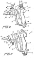
- the new and improved hot melt adhesive dispensing applicator gun 10 comprises an applicator gun housing 12 and a handle housing 14. More particularly, the applicator gun housing 12 comprises an upper applicator gun housing section 16, a lower applicator gun housing section 18, and a substantially L-shaped trigger cover housing section 20 which together with the applicator gun trigger member 22, of an applicator gun trigger assembly 24 which is best seen for example within FIGURE 4, defines an open space 26 within which the operator can insert his fingers so as to in fact be able to readily and comfortably operate the applicator gun trigger member 22.
- the applicator gun trigger member 22 comprises a four-finger trigger member 22.
- the integral applicator gun housing 12 and the handle housing 14 are both fabricated from or comprise mating half-housing sections which are adapted to be joined together along a vertical plane, as considered when the applicator gun 10 is disposed in its normal gun mode as seen in FIGURES 1 and 4, by means of a plurality of fasteners, for example, four fasteners, 28.
- the mating half-housing sections comprising the integral applicator gun housing 12 and the handle housing 14 can be separated so as to enable an operator to gain access to and expose the internal components of the applicator gun 10.
- the upper applicator gun housing section 16 is provided with a first recessed portion 30 and includes a radially inwardly projecting flanged portion 32.
- a hanger bracket 34 comprises an upper base section 36, a lower radially outwardly projecting flanged section 38, and an annular radially recessed section 40 interposed between the upper base section 36 and the lower flanged section 38.
- the hanger bracket 34 is adapted to be mounted within the recessed portion 30 of the upper applicator gun housing section 16, and when this is accomplished, the upper base section 36 of the hanger bracket 34 will be seated upon and disposed above the radially inwardly projecting flanged portion 32 of the upper applicator gun housing section 16, the lower flanged section of the hanger bracket 34 will be disposed beneath the radially inwardly projecting flanged portion 32 of the upper applicator gun housing section 16, and the radially inwardly projecting flanged portion 32 of the upper applicator gun housing section 16 will be disposed within the annular radially recessed section 40 of the hanger bracket 34.
- the hanger bracket 34 will effectively be trapped within the applicator gun 10 and between the two mating half housing sections comprising the integral applicator gun housing 12 and the handle housing 14 so as to enable the applicator gun 10 to be suspended from a suitable support, not shown, when, for example, the applicator gun 10 is not being used.
- the lower applicator gun housing section 18 is provided with a second recessed portion 42 and includes a radially inwardly projecting flanged portion 44.
- An electrical power cable connector 46 comprises a lower base section 48, an upper radially outwardly projecting flanged section 50, and an annular radially recessed section 52 interposed between the lower base section 48 and the upper flanged section 50.
- the electrical power cable connector 46 is adapted to be mounted within the recessed portion 42 of the lower applicator gun housing section 18, and when this is accomplished, the lower base section 48 of the electrical power cable connector 46 will be disposed beneath the flanged portion 44 of the lower applicator gun housing section 18, the upper radially outwardly projecting flanged section 50 of the electrical power cable connector 46 will be seated upon and disposed above the radially inwardly projecting flanged portion 44 of the lower applicator gun housing section 18, and the radially inwardly projecting flanged portion 44 of the lower applicator gun housing section 18 will be disposed within the annular radially recessed section 52 of the electrical power cable connector 46.
- the electrical power cable connector 46 will effectively be trapped within the applicator gun 10 so as to enable electrical power to be operatively transmitted to the applicator gun 10.
- the hanger bracket 34 may be removed from its disposition within the recessed portion 30 defined within the upper applicator gun housing section 16 and disposed within the recessed portion 42 defined within the lower applicator gun housing section 18, while the electrical power cable connector 46 may likewise in a reverse manner be removed from its disposition within the recessed portion 42 defined within the lower applicator gun housing section 18 and inserted within the recessed portion 30 defined within the upper applicator gun housing section 16.
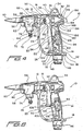
- This interchangeability or exchange of such component parts of the applicator gun 10 can be best appreciated, for example, as a result of reference being made to FIGURES 2 and 3. It is additionally noted that the electrical power cable is illustrated in FIGURE 2 at 54.
- the applicator gun 10 is further provided with a heater body housing assembly which comprises a heater body housing 56 within which a heater body member 58 is disposed.
- the heater body housing 56 is fabricated from or comprises mating half-housing sections which are adapted to be joined together along a vertical plane, as considered when the applicator gun 10 is disposed in its normal gun mode as seen in FIGURES 1 and 4, by means of a fastener 60 which is mounted within mating lug portions 62 which are integrally formed upon left end portions of the mating halves of the heater body housing 56.
- each mating half of the upper applicator gun housing section 16 is provided with a vertically oriented, radially inwardly projecting flanged portion 64 and a recessed region 66.
- the right end portion of each mating half of the heater body housing 56 similarly comprises a vertically oriented radially inwardly projecting annular base section 68 and a vertically oriented radially outwardly projecting flanged portion 70 which is axially spaced from and cooperates with base section 68 in defining an annular recessed portion 72 therebetween.
- each mating half of the heater body housing 56 when each mating half of the heater body housing 56 is to be mounted within each recessed region 66 defined within each left end portion of each mating half of the upper applicator gun housing section 16, the radially inwardly projecting flanged portion 64 of each mating half of the upper applicator gun housing section 16 will be disposed within the annular recessed portion 72 of each mating half of the heater body housing 56, the base section 68 of each mating half of the heater body housing 56 will be disposed upon the left side of the radially inwardly projecting flanged portion 64 of each mating half of the upper applicator gun housing section 16, and the radially outwardly projecting flanged portion 70 of each mating half of the heater body housing 56 will be disposed upon the right side of the radially inwardly projecting flanged portion 64 of each mating half of the upper applicator gun housing section 16.
- the heater body housing 56 will effectively be trapped within the upper applicator gun housing section 16 so as to be fixedly mounted upon the applicator gun 10.
- the heater body member 58 has a stem fitting member 74 fixedly attached thereto, and the stem fitting member 74 is adapted to mount a stem or connector member 76 therein.
- the stem or connector member 76 is adapted to be operatively connected to a hydraulic material supply hose 78 which fluidically supplies the hydraulic or adhesive material to the applicator gun 10, the hydraulic material supply hose 78 being illustrated within FIGURE 2.
- the applicator gun 10 is preferably provided with a tapered applicator nozzle 80, and a needle valve member 82, as best seen in FIGURE 5, is operatively associated with nozzle 80 so as to control the dispensing or discharge of the hot melt adhesive material from the applicator gun 10.
- Part of the longitudinal shank portion 84 of the needle valve member 82 is housed internally within the heater body member 58 such that heated hydraulic or adhesive material is disposed therearound and thereby able to be controlled by the needle valve member 82 in conjunction with the dispensing or discharge of the heated hydraulic or adhesive material from the applicator nozzle 80 when the needle valve member 82 is unseated from its valve seat, not shown.
- the shank portion 84 of the needle valve member 82 passes through a needle valve return spring housing 86, and the opposite end of the needle valve shank portion 84 is fixed within a needle pull collar 88.
- the upper end portion of the applicator gun trigger member 22 is provided with a forked portion comprising a pair of transversely spaced upstanding forked lug portions 90, only one of which is visible, and a rearward section of the needle valve shank portion 84 passes between the spaced upstanding forked lug portions 90.
- a transversely oriented dowel pin 92 passes through the upstanding forked lug portions 90 and has opposite ends thereof mounted within the mating half housing sections 16 so as to define a pivotal axis for the applicator trigger member 22.
- the disposition or orientation of the heater body housing 56 as mounted upon the upper applicator gun housing section 16 is desired to be changed such that, for example, the heater body member 58, and its operatively connected hydraulic or adhesive material stem or connector member 76 and hose 78, are in turn to be changed from the downwardly dependent orientation of FIGURE 1 to the upwardly extending orientation of FIGURE 2, then the mating half housing sections comprising the integral applicator gun housing 12 and the handle housing 14 are initially separated by removing the fasteners 28, and dowel pin 92 of the applicator gun trigger member 22 is also removed.
- the heater body housing 56 can then be re-inserted into the recessed portion 66 of the upper applicator gun housing section 16, and upon re-installing dowel pin 92 and re-attaching the mating half housing sections comprising the integral applicator gun housing 12 and the handle housing 14, the heater body housing 56, heater body member 58, and hydraulic or adhesive material stem or connector member 76 and hose 78, will be fixedly secured at their new orientation or disposition illustrated in FIGURE 2.
- orientation or disposition of the hydraulic or adhesive material supply hose 78 can be readily and quickly altered in a manner similar to that previously discussed in connection with the alteration of the orientation and disposition of the hanger bracket 34 and the electrical power cable 54 so as to accommodate, for example, various spatial or other requirements unique to a particular production facility or production line.
- an additional feature characteristic of the new and improved hot melt adhesive applicator gun 10 constructed in accordance with the principles and teachings of the present invention comprises the capability of the applicator gun 10 being optionally used with either a four-finger trigger member 22 as shown, for example, within FIGURES 1,3, and 4, or with a two-finger trigger member 22' as shown within FIGURES 2 and 6.
- the electrical power cable 54 comprises a plurality of electrical power wires, not shown, at least two of which are electrically connected to a cartridge heater assembly, not shown, and a temperature sensor assembly, also not shown, which are both operatively connected to the heater body member 58.
- an additional electrical power wire of power cable 54 is electrically connected to an electrical switch assembly 94 which, as best seen in FIGURE 4, is fixedly mounted within the applicator gun handle 14 and is adapted to electrically control, for example, the operation of an adhesive supply gear pump, not shown, or alternatively, the operation of a compressed air supply, also not shown, used in conjunction with the adhesive supply.
- the electrical switch assembly 94 has a microswitch element 96 operatively associated therewith, and the four-finger trigger member 22 is seen to comprise a rearwardly projecting heel portion 98 upon which the microswitch element 96 rests.
- the left or trigger side of the applicator gun handle housing 14 is open or slotted, and accordingly, when the trigger member 22 is squeezed so as to in effect cause the same to pivot around the axis of the dowel pin 92, the trigger member 22 will partially move through the open slotted portion of the handle housing 14 whereby the heel portion 98 of the trigger member 22 will cause microswitch element 96 to close the switch assembly 94.
- a two-finger trigger member 22' may be incorporated within the applicator gun 10 as illustrated in FIGURE 6 as a result of being effectively exchanged for the four-finger trigger member 22.
- the mating half housing sections comprising the integral applicator gun housing 12 and the handle housing 14 can be initially separated by removing the fasteners 28, and the dowel pin 92 is then removed from the illustrated mating half housing section.
- Applicator gun trigger member 22 is then removed from the illustrated mating half housing section by effectively moving or sliding the trigger member 22 downwardly, and the new trigger member 22' is inserted into the illustrated mating half housing section in a manner reverse to that of removing the trigger member 22, whereupon dowel pin 92 is re-inserted.
- the mating half housing sections comprising the integral applicator gun housing 12 and the handle housing 14 can then be subsequently mated together by re-installing the fasteners 28, however, prior to the mating of the housing half sections, a filler member or insert 100 must be inserted within the handle housing 14.
- FIGURES 4 and 6 it is seen that the structure of the two trigger members 22,22' are substantial-ly identical except for the fact that the longitudinal ex-tent of the two-finger trigger member 22' is only approxi-mately one-half of the longitudinal extent of the four-fing-er trigger member 22.
- each one of the mating half sections comprising the handle housing 14 has a pair of bosses 102,102 integrally formed upon an interior surface thereof, and each boss 102 is provided with a recessed or concave detent 104.
- the insert or filler member 100 is similarly provided upon opposite sides thereof with a pair of convex detents 106 which are adapted to be seated within the recessed or concave detents 104, and therefore, the filler member or insert 100 can be fixedly secured within the handle housing 14 when the mating half sections comprising the integral applicator gun housing 12 and the handle housing 14 are secured together by means of fasteners 28.
- the insert or filler member 100 in addition to preventing the operator's third or fourth finger from possibly being injured as a result of becoming caught or pinched within the otherwise open or slotted portion of the handle housing 14, the insert or filler member 100 also actually serves as a surface upon which such third and fourth fingers can rest comfortably while the first and second fingers of the operator are actually being used to operate the trigger member 22'.
- the trigger member 22' comprises a forward extending lower ledge portion 108 while the insert or filler member 100 similarly comprises a forward extending upper ledge portion 110 disposed immediately below the ledge portion 108 of the trigger member 22'.
- Such structures serve to in effect respectively seat the second and third fingers of the operator and maintain them separated so that neither one of such fingers can become jammed or pinched between the movable trigger member 22' and the fixed insert or filler member 100.
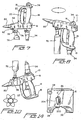
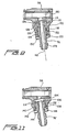
- the new and improved hot melt adhesive applicator gun 10 constructed in accordance with the principles and teachings of the present invention, it is often desired to utilize the applicator gun 10 in a variety of movement modes or orientations around at least one axis as illustrated within FIGURE 8, or still further, around three mutually orthogonal axes as shown within FIGURE 10 which therefore provides the applicator gun 10 with movements having six degrees of freedom.
- the heater body member 58 is provided with a recessed region 114 within which a thrust bearing seat member 116 is fixedly disposed.
- the hose stem or connector 76 is provided with an annular flanged portion 118 at an axially central portion thereof, and a pair of thrust bearing assemblies 120,122 are mounted upon opposite sides of the flanged portion 118.
- a plurality of roller bearings 124 are interposed between the inner peripheral surface of the annular stem fitting member 74 and the outer peripheral surface of the hose stem or connector 76, and in this manner, rotational movement of the hose stem or connector 76, and the hydraulic or adhesive material supply hose 78 operatively connected thereto, is facilitated and enabled.
- a static O-ring member 126 annularly surrounds the upper end portion of the thrust bearing seat member 116, and a pair of axially spaced O-ring members 128 are mounted upon the upper axial end portion of the hose stem or connector 76 so as to be rotatable therewith.
- a plurality of screw fasteners 130 fixedly maintain the assembly of components mounted upon heater body member 58.
- FIGURE 11 With reference alternatively being made to FIGURE 11, it is to be particularly noted that in the instance that it is desired to effectively convert the movement system for the applicator gun 10 from the system illustrated within FIGURE 9, wherein rotation of the applicator gun 10 is permitted around axis 112, to a movement system for the applicator gun 10 such as that illustrated within FIGURE 11 wherein movement of the applicator gun 10 is universally permitted around three mutually orthogonal axes, the same heater body member 58, having the same recessed region 114, is able to be utilized.
- the screw fasteners 130 are removed so as to effectively release or permit removal of all of the components mounted within the recessed region 114, and all of the components mounted within the recessed region 114 are then in fact removed.
- a hose stem or connector 76' having a universal ball unit 132 integrally provided upon the upper axial end portion thereof, is inserted within the recessed region 114.
- An annular wave washer or wave spring 134 is disposed within the upper axial portion of the recessed region 114, and an upper ball seat member 136 is also disposed within the recessed region 114.
- a lower ball seat member 138 is mounted within the mouth end portion of the heater body member 58 defining the recessed region 114, and an O-ring member 140 is interposed between the upper and lower ball seat members 136,138.
- An annular retainer member 142 is engaged with and mounted upon the mouth end portion of the heater body member 58, and a plurality of fasteners 144 are threadedly engaged within the heater body member 58 so as to retain all of the noted components at their respective positions.
- the applicator gun 10 is further provided with a trigger lock mechanism 146 which is operatively mounted upon a rear surface 148 of the upper applicator gun housing section 16 so as to be movable, as denoted by means of the double arrowhead, between a raised UNLOCKED position and a lowered LOCKED position.
- the rear end of the mechanism 146 comprises an operator finger button 150, and it is seen that the operator finger button 150 is integrally connected to a vertically oriented web portion 152.
- the bottom region of the web portion 152 has a transversely extending rib member 154 integrally connected thereto, and a lock block 156 is integrally connected to forward end portions of the web portion 152 and the rib member 154.
- the lock block 156 is provided with a threaded through-bore 158, a threadedly adjustable lock pin 160 is threadedly mounted within the threaded through-bore 158, and in order to retain the lock pin 160 at a predetermined position, a lock nut 162 is threadedly mounted upon the lock pin 160.
- an upper end portion 164 of the handle housing 14 forms a heel and is integrally joined to a lower rear end ledge portion 166 of the upper applicator gun housing section 16.
- the trigger member 22 is also seen to comprise a pair of rearwardly extending lug portions or ears 168, and a transversely oriented pin 170 is mounted within the lugs or ears 168.
- the lock pin 160 when the trigger lock mechanism 146 is disposed in the UNLOCKED state as a result of the finger button 150 being moved to the raised position, the lock pin 160 will be disposed above the lug portions or ears 168 and the transverse pin 170 of the trigger member 22 thereby permitting the trigger member 22 to in effect be moved rearwardly as a result of being pivoted upon its dowel pin 92 when the trigger member 22 is squeezed by the operator.
- the trigger lock mechanism 146 is disposed in the LOCKED state as a result of the finger button 150 being moved to its lowered position
- the lock block 156 will abut the heel portion 164 of the handle housing 14.
- the lock pin 160 will be engaged with the transverse pin 170 disposed within the trigger member lugs or ears 168, and therefore, rearward pivotal movement of the trigger member 22 is effectively prevented.
- the web portion 152 of the trigger lock mechanism 146 has a pair of oppositely extending transversely oriented detent fingers or arms 172.
- the tip portions 176 of the detent arms or fingers 172 are also adapted to operatively cooperate with recessed detents or notches, not shown, also defined upon interior surface portions of each mating half of the upper applicator gun housing section 16 such that when the trigger lock finger button 150 is moved to either one of its LOCKED or UNLOCKED positions, the detent tip portions 176 of the detent arms or fingers 172 will engage the recessed detents or notches, not shown, of the mating halves of the upper applicator gun housing section 16 in a tactile manner so as to indicate to the operator that the trigger lock finger button 150 has in fact achieved either one of the LOCKED and UNLOCKED states or positions.
- the needle valve return spring housing 86 has a needle valve seal assembly 182 fixedly mounted within a forward end portion thereof, and the needle valve seal assembly 182 has its forward end portion thereof fixedly mounted within the heater body member 58.
- the needle valve seal assembly 182 has an axial bore 184 defined therein through which the needle shank portion 84 is movably disposed, and a recessed portion 186 is defined within the forward end portion of the needle valve seal assembly 182 so as to house a plurality of seal or packing members 188 which actually perform the sealing function around and with respect to the needle shank portion 84 so as to prevent the leakage of any of the hydraulic or adhesive material rearwardly toward and into the upper applicator housing section 16 and the handle housing section 14.
- the needle valve return spring housing 86 has an interior chamber 190 defined therein, and the needle shank portion 84 has a shoulder portion 192 formed thereon which is disposed within the chamber 190 of the needle valve return spring housing 86.
- a return spring 194 is also disposed within the chamber 190 and has a first end thereof operatively engaged with the shoulder portion 192 of the needle shank portion 84 while the second end of the return spring 194 is operatively engaged with one side of an interior shoulder portion 196 of the needle valve return spring housing 86.
- the needle valve return spring 194 normally biases the needle valve member 82 toward its seated position with respect to nozzle 80.
- a trigger return spring collar 198 is movably mounted upon a rear end portion of the needle shank portion 84, and a coil return spring 200 is interposed between the collar 198 and the other side of the interior shoulder portion 196 of the needle valve return spring housing 86.
- the trigger member 22 has a portion thereof, not shown, which is adapted to be interposed between the return spring collar 198 and the needle pull collar 88, and in this manner, when the trigger member 22 is squeezed and pivoted in the counterclockwise direction around dowel 92, the upper portion of the trigger member 22 defined between upstanding lugs or ears 90 acts upon needle pull collar 88, which is fixed upon the end of the needle shank portion 84 by means of a screw 202, so as to move needle pull collar 88 toward the right as viewed in FIGURE 5 so as to unseat needle valve 82 from its valve seat, not shown, within the nozzle 80.
- needle valve return spring 194 will again seat the needle valve 82 upon its valve seat as a result of acting upon needle valve shoulder portion 192, and coil return spring 200 maintains the trigger member 22 engaged with the pull collar 88 as a result of acting upon the return spring collar 198.
- the trigger member 22 is therefore readied for a subsequent actuation movement.
- the applicator gun 10 will experience hydraulic or adhesive material leakage into both the upper applicator gun housing section 16 and the handle housing 14 thereby fouling the component parts thereof. It is therefore important to detect any leakage as early as possible and to contain such leakage as best as possible so that fouling of applicator gun components, as well as external articles, is minimized.
- a transversely oriented weep hole or window 204 is defined within or through the upper applicator gun.housing section 16 such that, for example, as best seen in FIGURE 14, the rearward portion of the needle valve return spring housing 86 and the coil return spring 200 are visible.
- the weep hole or window 204 will afford an early warning or detection mechanism by means of which the operator can detect such leakage and take appropriate maintenance steps to correct such leakage, namely, taking apart the applicator gun 10 and replacing the seal and packing members 188 as required.
- the weep hole or window 204 comprises an enclosed region, such structure effectively serves to contain for a predetermined period of time the leaking hydraulic or adhesive material such that the same does not also foul external portions of the applicator gun 10 or external articles present within the vicinity of the applicator gun 10.
- a new and improved applicator gun wherein various external connections, such as, for example, for the gun hanger bracket and electrical power cable, can be readily interchanged, as can the orientation of the hydraulic or adhesive material supply hose operatively associated with the heater body housing.
- the applicator gun itself can be utilized within an inverted mode, and still further, the applicator gun can be equipped with either a four-finger trigger mechanism or a two-finger trigger mechanism. Accordingly, the applicator gun is capable of being used in a variety of orientations so as to satisfy spatial requirements, cable routing requirements, and the like.
- the heater body housing comprises internal structure which enables the applicator gun to be operated in both a rotational mode around a single linear axis, or alternatively, in a universal mode comprising movements having six degrees of freedom with respect to three mutually orthogonal axes.
- the applicator gun has unique tactile detent structure incorporated into its trigger lock mechanism so as to indicate to the operator the achievement of the LOCKED and UNLOCKED states, and lastly, the applicator gun has incorporated therein a weep hole or window for achieving early detection of the occurrence of the adhesive material leakage whereby the leakage of the adhesive material is not able to migrate or propagate into the applicator gun handle housing so as not to foul any of the components therein.
- one side portion of the handle housing 14 is open as a result of a slot being defined therein for accommodating the trigger members 22,22' when they are actuated to their squeezed positions
- the lower half of the trigger member 22 in lieu of partially entering the slotted portion of the handle housing 14, could be disposed externally of the handle housing 14 and effectively envelop or surround the lower external portion of the handle housing 14 when the trigger member 22 is moved to the actuated squeezed state.
- the solid or closed lower half of the handle housing 14 obviates the needs for a separate cover, filler, insert, or the like such as that disclosed at 100.
- the critically important characteristic of the handle housing 14 and the trigger members 22,22' mounted thereon resides in the fact that the lower portion of the handle housing 14 is always effectively covered in some manner or by some means so as to protect the operator's fingers. It is therefore to be understood that within the scope of the appended claims, the present invention may be practiced otherwise than as specifically described herein.
Landscapes
- Engineering & Computer Science (AREA)
- Mechanical Engineering (AREA)
- Coating Apparatus (AREA)
Applications Claiming Priority (2)
| Application Number | Priority Date | Filing Date | Title |
|---|---|---|---|
| US09/947,476 US6412662B1 (en) | 2001-09-07 | 2001-09-07 | Hot melt adhesive hand applicator |
| EP02015754A EP1291089A3 (de) | 2001-09-07 | 2002-07-13 | Pistole zum Auftragen von Heissschmelzklebern |
Related Parent Applications (1)
| Application Number | Title | Priority Date | Filing Date |
|---|---|---|---|
| EP02015754A Division EP1291089A3 (de) | 2001-09-07 | 2002-07-13 | Pistole zum Auftragen von Heissschmelzklebern |
Publications (2)
| Publication Number | Publication Date |
|---|---|
| EP1679129A2 true EP1679129A2 (de) | 2006-07-12 |
| EP1679129A3 EP1679129A3 (de) | 2006-11-02 |
Family
ID=25486198
Family Applications (4)
| Application Number | Title | Priority Date | Filing Date |
|---|---|---|---|
| EP02015754A Withdrawn EP1291089A3 (de) | 2001-09-07 | 2002-07-13 | Pistole zum Auftragen von Heissschmelzklebern |
| EP06007345A Withdrawn EP1679127A3 (de) | 2001-09-07 | 2002-07-13 | Pistole zum Auftragen von Heissschmelzklebern |
| EP06007455A Withdrawn EP1679129A3 (de) | 2001-09-07 | 2002-07-13 | Pistole zum Auftragen von Heissschmelzklebern |
| EP06007346A Withdrawn EP1679128A3 (de) | 2001-09-07 | 2002-07-13 | Pistole zum Auftragen von Heissschmelzklebern |
Family Applications Before (2)
| Application Number | Title | Priority Date | Filing Date |
|---|---|---|---|
| EP02015754A Withdrawn EP1291089A3 (de) | 2001-09-07 | 2002-07-13 | Pistole zum Auftragen von Heissschmelzklebern |
| EP06007345A Withdrawn EP1679127A3 (de) | 2001-09-07 | 2002-07-13 | Pistole zum Auftragen von Heissschmelzklebern |
Family Applications After (1)
| Application Number | Title | Priority Date | Filing Date |
|---|---|---|---|
| EP06007346A Withdrawn EP1679128A3 (de) | 2001-09-07 | 2002-07-13 | Pistole zum Auftragen von Heissschmelzklebern |
Country Status (3)
| Country | Link |
|---|---|
| US (1) | US6412662B1 (de) |
| EP (4) | EP1291089A3 (de) |
| JP (1) | JP2003200092A (de) |
Cited By (1)
| Publication number | Priority date | Publication date | Assignee | Title |
|---|---|---|---|---|
| CN107893523A (zh) * | 2017-11-08 | 2018-04-10 | 武汉科技大学 | 一种基于4自由度的自动化墙面抹灰机 |
Families Citing this family (17)
| Publication number | Priority date | Publication date | Assignee | Title |
|---|---|---|---|---|
| CA2485487C (en) * | 2002-05-17 | 2012-10-23 | Tyco Healthcare Group, Lp | Wound closure material applicator |
| US6698671B1 (en) * | 2002-12-17 | 2004-03-02 | Shin Tai Spurt Water Of The Garden Tools Co., Ltd. | Movable shield structure of a flow control valve rod of a pistol-type nozzle |
| US6938795B2 (en) * | 2003-11-26 | 2005-09-06 | Nordson Corporation | Hand-held fluid dispenser system and method of operating hand-held fluid dispenser systems |
| USD511446S1 (en) | 2004-06-29 | 2005-11-15 | Nordson Corporation | Body for a hand-held fluid dispenser |
| US20060191957A1 (en) * | 2004-10-13 | 2006-08-31 | Hyperion Innovations Inc. | Glue dispensing apparatus |
| US20060081650A1 (en) * | 2004-10-13 | 2006-04-20 | Hyperion Innovations, Inc. | Glue dispensing apparatus |
| USD541121S1 (en) * | 2004-11-18 | 2007-04-24 | Hyperion Innovations, Inc. | Liquid dispensing apparatus |
| EP2074053B1 (de) * | 2006-09-01 | 2014-11-12 | MWV Slatersville, LLC. | Abgabeverschluss |
| DE102008003909A1 (de) * | 2007-07-17 | 2009-02-26 | Netzsch-Mohnopumpen Gmbh | Handauftragseinheit |
| EP2250204A4 (de) * | 2008-02-26 | 2012-01-25 | Fuller H B Co | Energieaktivierte bei raumtemperatur pumpbare polymerzusammensetzungen und vorrichtung für ihre aktivierung und ausgabe |
| EP2274107B1 (de) * | 2008-05-14 | 2014-09-03 | Robatech AG | Handauftraggerät |
| US20130020015A1 (en) * | 2011-01-07 | 2013-01-24 | Ofs Fitel, Llc | Apparatus and Methods for Routing an Optical Fiber or Cable Inside a Building or Living Unit |
| JP6984849B2 (ja) * | 2018-07-27 | 2021-12-22 | 旭サナック株式会社 | 塗布ガン |
| JP7025737B2 (ja) * | 2018-07-27 | 2022-02-25 | 旭サナック株式会社 | 塗布ガン |
| JP7025736B2 (ja) * | 2018-07-27 | 2022-02-25 | 旭サナック株式会社 | 塗布ガン |
| US12208408B2 (en) * | 2021-10-21 | 2025-01-28 | Nexshift, Inc. | Spray bottle having hinging and locking spray head assembly with replaceable components, and multi-label systems |
| CN116733818B (zh) * | 2023-06-11 | 2025-08-29 | 浙江大学 | 一种热熔胶连接件及其使用方法 |
Family Cites Families (19)
| Publication number | Priority date | Publication date | Assignee | Title |
|---|---|---|---|---|
| US1929662A (en) * | 1930-08-16 | 1933-10-10 | Wappat Inc | Motor driven tool switch |
| US3393676A (en) * | 1964-09-28 | 1968-07-23 | Ritter Pfaudler Corp | Dental instrument assembly |
| US3543968A (en) * | 1969-03-20 | 1970-12-01 | Nordson Corp | Gun for dispensing thermoplastic materials |
| US3780953A (en) * | 1972-01-21 | 1973-12-25 | J Malec | Airless spray gun |
| US3847233A (en) * | 1973-06-29 | 1974-11-12 | Black & Decker Mfg Co | Trigger mechanism for hand-operated power device providing automatic lock-off and manual lock-on operation |
| US3913844A (en) * | 1974-03-13 | 1975-10-21 | Graco Inc | Safety spray gun trigger |
| US3971492A (en) * | 1974-09-30 | 1976-07-27 | Lockwood Technical, Inc. | Hot melt applicator gun |
| US4245759A (en) * | 1979-05-02 | 1981-01-20 | Nordson Corporation | Adhesive hand gun with swivel connector and safety mechanism |
| US4449696A (en) * | 1981-10-21 | 1984-05-22 | Hengesbach Robert W | Valve with handle-mounting ring |
| US4708292A (en) * | 1985-06-05 | 1987-11-24 | Olin Corporation | Foam dispensing gun with improved mixing chamber |
| US5236129A (en) * | 1992-05-27 | 1993-08-17 | Ransburg Corporation | Ergonomic hand held paint spray gun |
| DE4339302C2 (de) * | 1993-11-18 | 1999-12-30 | Abb Patent Gmbh | Farbwechselblock mit Leckageindikatoren |
| US5507534A (en) * | 1994-04-29 | 1996-04-16 | Nordson Corporation | Hydraulic ball style swivel fitting |
| US5803313A (en) * | 1996-05-21 | 1998-09-08 | Illinois Tool Works Inc. | Hand held fluid dispensing apparatus |
| CA2189626A1 (en) * | 1996-11-05 | 1998-05-05 | Jean-Francois Hamel | Spray gun with double trigger levers for dispensing two liquids independently or in admixture |
| US5833147A (en) * | 1997-01-13 | 1998-11-10 | Abb Flexible Automation Inc. | Rotary union for robotic end effector |
| DE19753146A1 (de) * | 1997-11-29 | 1999-06-02 | Adolf Wuerth Gmbh & Co Kg | Ausgabegerät für Kartuschen |
| WO2001026866A2 (en) * | 1999-10-13 | 2001-04-19 | Rodney William Baker | Improved air or water hand held cleaning gun |
| US6415958B1 (en) * | 2002-01-07 | 2002-07-09 | Illinois Tool Works, Inc. | Needle valve actuator for hot melt adhesive hand applicator and a method for operating the same |
-
2001
- 2001-09-07 US US09/947,476 patent/US6412662B1/en not_active Expired - Lifetime
-
2002
- 2002-07-13 EP EP02015754A patent/EP1291089A3/de not_active Withdrawn
- 2002-07-13 EP EP06007345A patent/EP1679127A3/de not_active Withdrawn
- 2002-07-13 EP EP06007455A patent/EP1679129A3/de not_active Withdrawn
- 2002-07-13 EP EP06007346A patent/EP1679128A3/de not_active Withdrawn
- 2002-09-09 JP JP2002263197A patent/JP2003200092A/ja active Pending
Non-Patent Citations (1)
| Title |
|---|
| None |
Cited By (1)
| Publication number | Priority date | Publication date | Assignee | Title |
|---|---|---|---|---|
| CN107893523A (zh) * | 2017-11-08 | 2018-04-10 | 武汉科技大学 | 一种基于4自由度的自动化墙面抹灰机 |
Also Published As
| Publication number | Publication date |
|---|---|
| EP1679129A3 (de) | 2006-11-02 |
| EP1291089A3 (de) | 2005-08-10 |
| EP1679128A3 (de) | 2006-11-02 |
| EP1679128A2 (de) | 2006-07-12 |
| US6412662B1 (en) | 2002-07-02 |
| EP1679127A3 (de) | 2006-11-02 |
| JP2003200092A (ja) | 2003-07-15 |
| EP1679127A9 (de) | 2007-04-04 |
| EP1291089A2 (de) | 2003-03-12 |
| EP1679127A2 (de) | 2006-07-12 |
Similar Documents
| Publication | Publication Date | Title |
|---|---|---|
| US6412662B1 (en) | Hot melt adhesive hand applicator | |
| US4245759A (en) | Adhesive hand gun with swivel connector and safety mechanism | |
| KR100214107B1 (ko) | 핸드 헬드 유체 분산 장치 | |
| EP2463533B1 (de) | Kugelgelenk mit einem Durchgang zur Durchführung von Kabeln | |
| US8402997B2 (en) | Fluid flow control cock fitted with a lever having several stable positions | |
| CA1105804A (en) | Cylinder valve for gas fire extinguishing system and system embodying same | |
| CA1080467A (en) | Molten adhesive dispensing device | |
| US8225964B2 (en) | Self-locking handheld adhesive dispensers and methods of using such adhesive dispensers | |
| US4709859A (en) | High pressure washing apparatus | |
| CA2147234A1 (en) | Hydraulic ball style swivel fitting | |
| CA2667131C (en) | Pneumatic system electrical contact device | |
| US20220280968A1 (en) | Autonomous dispensing effector unit for a robotic arm | |
| EP0148981A1 (de) | Betätigungsvorrichtung für Kugelhähne | |
| US4260130A (en) | Valve for corrosive fluids | |
| JPS60159500A (ja) | グリス給油装置 | |
| KR20140132107A (ko) | 분사압력 조절형 스프레이건 | |
| US5399837A (en) | Wire brake for robotic welding torch | |
| US6279608B1 (en) | Connection for connecting a measuring device to a gas unit | |
| CA3169199A1 (en) | Valve with integrated pressure regulator | |
| CN1321878A (zh) | 温度监控装置 | |
| EP0068743A1 (de) | Feuerlöschvorrichtungen | |
| CA1086049A (en) | Molten adhesive dispensing device | |
| GB2322688B (en) | Thermostatic valve control head | |
| MXPA97002786A (en) | Manufacturing device flui manufacturer | |
| PL171648B1 (pl) | Pistolet do płynu |
Legal Events
| Date | Code | Title | Description |
|---|---|---|---|
| PUAI | Public reference made under article 153(3) epc to a published international application that has entered the european phase |
Free format text: ORIGINAL CODE: 0009012 |
|
| AC | Divisional application: reference to earlier application |
Ref document number: 1291089 Country of ref document: EP Kind code of ref document: P |
|
| AK | Designated contracting states |
Kind code of ref document: A2 Designated state(s): AT BE BG CH CY CZ DE DK EE ES FI FR GB GR IE IT LI LU MC NL PT SE SK TR |
|
| AX | Request for extension of the european patent |
Extension state: AL LT LV MK RO SI |
|
| PUAL | Search report despatched |
Free format text: ORIGINAL CODE: 0009013 |
|
| AK | Designated contracting states |
Kind code of ref document: A3 Designated state(s): AT BE BG CH CY CZ DE DK EE ES FI FR GB GR IE IT LI LU MC NL PT SE SK TR |
|
| AX | Request for extension of the european patent |
Extension state: AL LT LV MK RO SI |
|
| RIN1 | Information on inventor provided before grant (corrected) |
Inventor name: DONLEY, PAUL J. Inventor name: BOURGET, DANIEL D. Inventor name: BRYAN, CHRISTOPHER D. |
|
| 17P | Request for examination filed |
Effective date: 20061214 |
|
| 17Q | First examination report despatched |
Effective date: 20070116 |
|
| AKX | Designation fees paid |
Designated state(s): DE GB IT |
|
| STAA | Information on the status of an ep patent application or granted ep patent |
Free format text: STATUS: THE APPLICATION IS DEEMED TO BE WITHDRAWN |
|
| 18D | Application deemed to be withdrawn |
Effective date: 20100202 |