EP1679124B1 - Trennvorrichtung mit einem Trennkanal und einem Gegenkanal - Google Patents
Trennvorrichtung mit einem Trennkanal und einem Gegenkanal Download PDFInfo
- Publication number
- EP1679124B1 EP1679124B1 EP06290035A EP06290035A EP1679124B1 EP 1679124 B1 EP1679124 B1 EP 1679124B1 EP 06290035 A EP06290035 A EP 06290035A EP 06290035 A EP06290035 A EP 06290035A EP 1679124 B1 EP1679124 B1 EP 1679124B1
- Authority
- EP
- European Patent Office
- Prior art keywords
- separation
- channel
- mounting component
- recess
- mounting
- Prior art date
- Legal status (The legal status is an assumption and is not a legal conclusion. Google has not performed a legal analysis and makes no representation as to the accuracy of the status listed.)
- Expired - Lifetime
Links
Images


Classifications
-
- B—PERFORMING OPERATIONS; TRANSPORTING
- B04—CENTRIFUGAL APPARATUS OR MACHINES FOR CARRYING-OUT PHYSICAL OR CHEMICAL PROCESSES
- B04B—CENTRIFUGES
- B04B5/00—Other centrifuges
- B04B5/04—Radial chamber apparatus for separating predominantly liquid mixtures, e.g. butyrometers
-
- B—PERFORMING OPERATIONS; TRANSPORTING
- B04—CENTRIFUGAL APPARATUS OR MACHINES FOR CARRYING-OUT PHYSICAL OR CHEMICAL PROCESSES
- B04B—CENTRIFUGES
- B04B5/00—Other centrifuges
- B04B5/04—Radial chamber apparatus for separating predominantly liquid mixtures, e.g. butyrometers
- B04B5/0442—Radial chamber apparatus for separating predominantly liquid mixtures, e.g. butyrometers with means for adding or withdrawing liquid substances during the centrifugation, e.g. continuous centrifugation
- B04B2005/045—Radial chamber apparatus for separating predominantly liquid mixtures, e.g. butyrometers with means for adding or withdrawing liquid substances during the centrifugation, e.g. continuous centrifugation having annular separation channels
-
- G—PHYSICS
- G01—MEASURING; TESTING
- G01N—INVESTIGATING OR ANALYSING MATERIALS BY DETERMINING THEIR CHEMICAL OR PHYSICAL PROPERTIES
- G01N30/00—Investigating or analysing materials by separation into components using adsorption, absorption or similar phenomena or using ion-exchange, e.g. chromatography or field flow fractionation
- G01N30/0005—Field flow fractionation
- G01N2030/0015—Field flow fractionation characterised by driving force
- G01N2030/002—Field flow fractionation characterised by driving force sedimentation or centrifugal FFF
Definitions
- the invention relates to a device for separating solutions containing substances suspended in a carrier liquid, advantageously used as a separation bowl in a centrifuge, preferably by a flow-force coupling (FFF) fractionation technique.
- a carrier liquid advantageously used as a separation bowl in a centrifuge, preferably by a flow-force coupling (FFF) fractionation technique.
- FFF flow-force coupling
- the present inventors in particular Professor CARDOT, have also made several publications in this field. In particular, they have perfected flux-force fractionation sedimentation, in particular for the separation of living human cells using the force of gravity induced by the rotation of a separation bowl.
- these devices have encountered the same problems as in the devices of the prior art.
- the present inventors have in particular identified a problem of deformation of the separation volume defined by the annular channel of rectangular cross section. This deformation occurs especially during the clamping of the channel for its introduction into the separation bowl.
- the main purpose of the invention is to solve the technical problem consisting in the provision of a new separation device, in particular fractionation by flux-force coupling (FFF), allowing a reproducible separation of substances suspended in a carrier liquid, by particularly by restoring the Gaussian form of the elution peaks and / or by obtaining reproducible retention times.
- FFF flux-force coupling
- the invention also aims to solve the technical problem of providing a new separation device, including FFF, in particular FFF by sedimentation (gravitational field), allowing the separation of living cells in a reproducible manner.
- FFF FFF
- FFF sedimentation
- These cells are in particular human cells, preferably cells present in physiological fluids, in particular in the blood, such as red blood cells.
- the invention also aims to solve the new technical problem of finding a technical solution that avoids the deformation of a substantially annular separation channel of substantially rectangular section, in particular an FFF separation channel.
- the invention also aims to solve the technical problem of providing a device easily removable on the one hand for cleaning, including sterilization / decontamination, easy; and on the other hand allow a device change, in particular so as to modify the properties of the separation channel for the separation of different substances, possibly in a different carrier liquid. This change is particularly necessary in the frequent case of treating different biological fluids from different carriers, especially to prevent contamination.
- the invention also aims to solve the technical problem of providing a separation device for a very high flexibility of use, including allowing to change the geometric parameters of the separation device quickly while having a wide choice as to the separation device used.
- the present invention describes in a first aspect a device for separating solutions containing substances suspended in a carrier liquid, especially in the context of a centrifugation, comprising a housing comprising a cavity defining a substantially cylindrical internal surface of a predetermined height, and at least a first substantially rectangular annular substantially cylindrical sectional dividing channel of substantially rectangular cross-section formed by the combination of three mounting elements of sufficient size to, in mounted position, substantially completely cover said inner surface substantially cylindrical of said cavity, namely a first mounting member having a wall portion defining at least a first side wall of said dividing channel, a second mounting member having at least one recess defining a second side wall of said dividing channel and the dimension of said separation channel, and a third mounting element being positioned against the second element, defining a third side wall and completing said separation channel, characterized in that it comprises at least a second channel called channel against, disposed opposite the first separation channel, between the first mounting member and said inner wall of the housing cavity.
- the thickness of the second mounting element defines the thickness of the first separation channel; and in that the thickness of the counter channel is substantially the same as the thickness of the first separation channel.
- This thickness is generally between 0.050 and 2 mm, preferably between 0.070 and 0.200 mm, for example between 0.100 and 0.175 mm.
- the cross section of the counter channel is greater than the cross section of the first separation channel, in particular in the corresponding direction in the mounted position to the cylindrical wall.
- the second mounting member comprising said recess is made of a material having mechanical properties different from the material of the first mounting member and / or the third mounting member.
- the second mounting element is made of a material having sufficient mechanical properties to be essentially free of creep, in particular under the effect of a clamping pressure.
- the counter channel is formed by the combination of a fourth mounting element disposed between the first mounting member and the inner wall of the housing and comprising a second recess at least as large as the first recess, said second recess being arranged, in the mounted state, facing the first recess, and a fifth mounting member disposed against the inner wall of said housing cavity.
- the second mounting member is formed from a substantially planar sheet in which the aforesaid recess is formed by cutting with preferably beveled lateral end edges.
- the fourth mounting member is made of a material having mechanical properties similar or substantially identical to the material of the second mounting member.
- the material of the second mounting element is made at least partly, or preferably totally, of a sterilizable material and whose surface can be treated to limit adsorption, in particular a plastic material selected from the group consisting of a metallized plastic sheet such as mylar, a polycarbonate, or a metal or alloy of at least one metal, in particular a biocompatible metal such as aluminum, a noble stainless metal.
- a plastic material selected from the group consisting of a metallized plastic sheet such as mylar, a polycarbonate, or a metal or alloy of at least one metal, in particular a biocompatible metal such as aluminum, a noble stainless metal.
- the other mounting elements are also made of a sterilizable material as defined in the above paragraph.
- the second mounting member and the fourth mounting member are identical in material.
- This material is preferably a metallized plastic sheet such as mylar whose thickness as previously indicated is preferably between 0.050 and 2 mm, preferably between 0.070 and 0.200 mm, as per example between 0.100 and 0.175 mm.
- the thickness of the fourth mounting member is about 10% greater than the thickness of the second mounting member.
- the thickness of the fourth mounting element is 110 ⁇ m when the thickness of the second mounting element is 100 ⁇ m.
- the first, third and fifth mounting members are also preferably made of an identical material, the thickness of which is preferably between 0.050 and 2 mm, preferably between 0.070 and 0.200 mm, for example between 0.100 and 0.175 mm. .
- This material is preferably a polycarbonate.
- the counter-channel device makes it possible to avoid the deformation of the separation volume defined by the hollow volume of the channel during a powerful clamping which is necessary to ensure the seal between the three mounting elements defining the separation channel.
- This counter-channel device and the separation channel device also make it possible to obtain an easily interchangeable assembly so as to change, for example, the materials, the dimensions, the housing, or other parameters, in particular to modify the separation parameters. .
- the material of the second mounting element is particularly advantageous for the material of the second mounting element to be compatible with biological substances, in particular living cells that can be transported in particular. These materials are in particular those known to those skilled in the art for such uses.
- This clamping mode is quite usable in other devices.
- it makes it possible to distribute the clamping forces substantially equally over the periphery of the channel.
- This device allows also to achieve a uniform clamping of the annular separation channel.
- the device according to the present invention comprises at least one clamping member disposed inside said cavity of the housing, and having a substantially equal height, preferably identical, to the height of said cavity of the housing, to bear against substantially all of the apparent surface of the third mounting member.
- the clamping member comprises at least two distinct clamping elements of complementary trapezoidal section having a contiguous contact surface inclined plane defined by the inclined edge of the trapezoidal section.
- the first clamping element intended to bear against the third separating element, has a trapezoidal-shaped ring shape, advantageously cut into several distinct parts.
- the second clamping member has substantially a disk shape whose outer edge defines said inclined plane of the trapezoidal section provided to cooperate with the inclined plane of the trapezoidal section of the first clamping element.
- the present invention implements a device for entering and / or leaving the carrier liquid in the separation channel, making it possible to introduce the carrier liquid through the outer periphery of the separating bowl. That is, an inlet and / or outlet conduit passes through the housing, the counter channel, and the first channel mounting member.
- an inlet and / or outlet conduit passes through the housing, the counter channel, and the first channel mounting member.
- the input device and / or output allows to introduce the carrier liquid from the inside of the separation bowl.
- Devices of this type are known in the prior art.
- the first mounting element comprises at least two through orifices intended to constitute respectively an inlet orifice and an outlet orifice of the liquid solution to be separated in said separation channel.
- the device comprises in the body of the housing at least two through housings for each receiving at least one piece of adjustment of the flow seals of the inlet and the outlet of said liquid solution, comprising at least one receiving orifice of a clamping screw itself provided with a through orifice serving respectively to the inlet or the outlet of said liquid solution to the inlet or outlet orifice; exit of the fifth element.
- the adjustment piece is movably mounted to allow translational movement of this piece along the wall of the housing.
- a slider or channel system provides the adjustment piece with a sufficient degree of freedom.
- Said housings are entirely independently patentable in that they can be adapted to the housing serving as a separation bowl so as to facilitate adjustment of the inlet and the outlet.
- the positioning of the inlet and outlet ports of the separation channel is particularly dependent on the clamping force or pressure.
- the through housings are advantageously located at the outer periphery of the housing.
- the present invention has solved this technical problem by providing a mobile liquid supply system to be separated, which greatly simplifies channel and counter channel mounting tasks in a separator bowl housing.
- the problem of adjusting the inlet and the outlet is particularly encountered when the position of the inlet and outlet ports of the channel is identified before tightening the assembly or when the clamping applied to the channel assembly and against channel is not of identical strength. This also makes it possible to obtain a degree of freedom as to the length of the separation channel.
- This mobile system advantageously allows the implementation of a mounting method in which the different elements forming respectively the channel and the counter channel can be blinded. The process is described in more detail in the detailed description of the invention.
- the present invention relates to a separation apparatus comprising a separation device as described above.
- the separation device is mounted on an axis of rotation and is between two fixed parts ensuring the maintenance of the axis of rotation at the distal end portion and at the proximal end portion.
- the separating apparatus is asymmetrical, to allow rapid disassembly, and comprises a single fixed part intended to support an axis of rotation, said fixed part being situated between a driving device, such as a motor, to drive the separation device in rotation about the axis of rotation, and the separation device.
- the device according to the present invention may be rotated either about a substantially horizontal axis of rotation, or about a substantially vertical axis of rotation. It is preferred to use a substantially horizontal axis of rotation, in particular for the ease of implementation, in particular the assembly and disassembly operation.
- the apparatus comprises substantially two distinct zones, namely a first easily accessible separation zone comprising the separation device, and a second so-called training zone comprising the drive device.
- This aspect of the invention is also independently patentable insofar as the fact of carrying out an asymmetric mounting and / or of physically separating the zone comprising the separation device and the zone comprising the driving device makes it possible to secure any centrifugation apparatus particularly as to the training part, while keeping easily accessible the separation part. This is particularly advantageous when the apparatus is asymmetrical and allows easy and very fast assembly / disassembly of the separation bowl, in particular the separation device according to the present invention.
- the second training zone is located below the first zone. This allows to keep accessible from the front from the upper part, to perform a manipulation of the separation device and the lower part, to perform a maintenance operation on the drive means.
- the separation device or the apparatus as described above is used for the separation of particles suspended in a carrier liquid, in particular by centrifugation, preferably by a force flow fractionation technique called FFF, in particular of living cells, in particular living cells of human origin.
- FFF force flow fractionation technique
- the particles in suspension are colloids, for example titanium dioxide.
- the particles in suspension are living cells, in particular stem cells.
- Such separation was not possible until then by the systems described in the prior art since it did not allow a good reproducibility of the separation.
- the living cells to be separated are living cells selected from the group consisting of red blood cells, avian stem cells, neural stem cells, precursor cells in gliomas, precursor cells in neuroblastomas, glial cells. cell lines.
- the present invention also allows the separation of other biological molecules in suspension, for example proteins, such as antibodies, or amino acids, such as DNA, RNA, virus.
- the substances to be separated can advantageously be of human origin.
- the device according to the present invention thus makes it possible to adapt the FFF technique to the separation of living biological cells, and in particular transplantable cells.
- the device according to the present invention makes it possible to identify new cells, which represents a considerable advance in human and animal, cosmetological and industrial medical applications.
- the device according to the present invention also makes it possible to overcome the absence and / or ignorance of the biological markers present on the cells.
- the figure 1 shows in particular an example of a device 1 for separating solutions containing substances suspended in a carrier liquid, particularly in the context of a centrifugation, comprising a housing 100 comprising a cavity 110 defining a substantially cylindrical internal surface 120 of a height predetermined, namely generally between 1 and 15 cm although this is not limiting.
- the housing 100 comprises a positioning means 150, such as a central through hole for the passage or fixing of the housing 100 on a shaft 702 for rotating said housing 100 and at least a first separation channel 200.
- the positioning means 150 is adapted to receive a rotary joint device, allowing the entry and / or exit of the carrier liquid by input and / or output conduits 131 and 141.
- This device is characterized according to the invention in that it comprises at least one second channel 300 called against channel, disposed opposite the first separation channel 200, between the first mounting member 10 and said inner wall 120 of the cavity 110 of the housing 100.
- the clamping member 400 comprises at least two separate clamping elements (410, 420) of complementary trapezoidal section having a contiguous contact surface with an inclined plane.
- the first clamping element 410 intended to bear against the third separating element 30, has a hollow cylindrical shape trapezoidal section, cut into several separate parts, for example two separate parts (415,416) or three separate parts in order to distribute as best as possible the clamping pressure force. It will be understood that the vertical outer edge 414 of the first clamping element 410 constitutes the clamping bearing surface against the apparent surface 34 of the third mounting element 30.
- the second clamping element 420 has essentially a disk shape whose outer edge 422 defines said inclined plane of the trapezoidal section, designed to cooperate with the inclined plane of the trapezoidal section of the first clamping element 410, formed by the 412 inner edge.
- the two clamping elements (410,420) held integrally on the housing 100 by holding means 430, such as screws known to those skilled in the art to ensure an equal distribution of the forces exerted during the tightening of a clamping member, such as the second clamping member 420. This is entirely advantageously so as not to deform the entire separation channel 200, against channel 300.
- the first mounting element 10 comprises at least two through orifices 13, 14 intended respectively to constitute an inlet orifice 13 and an outlet orifice 14 of the liquid solution to be separated in the said separation channel 200.
- the fifth mounting member 50 also has the same orifices 53 and 54.
- the housing 100 also has two through holes (130, 140) for ensuring the entry and exit of the liquid solution to be separated in said separation channel 200.
- Through-holes (13, 14, 53, 54, 130, and 140) allow introduction of inlet means (131) and outlet (141) of the carrier liquid comprising substances to be separated.
- These means are, for example, chromatography tubes, such as tubes for HPLC.
- the mounting of these tubes is effected hermetically so that the carrier liquid and the substances to be separated that must pass through the separation channel are not found in the recess 42 of the counter channel.
- the casing 100 is for example of an effective internal diameter of the separation cavity 110 of 30 cm.
- the diameters of the housings 100 will generally be between 5 and 50 cm, preferably between 8 and 15 cm and will vary depending on the desired separation. The lower the case mass, the higher the potential rotation speeds.
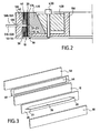
- the figure 2 shows a cross section of the device according to the figure 1 in a tightly maintained operating position.
- an element 500 serving at the inlet 510 or an element 501 serving at the outlet 520 of the liquid solution to be separated into the inlet orifice 130 or the outlet orifice 140.
- the element 500, 501 is advantageously positioned facing the beveled end of the recess defining the separation channel 200, being substantially tangential to the inner surface 12 of the first element 10.
- the elements 500,501 enter the fifth mounting element 50 through the through orifices 53, 54 and pass through the channel in the recessed portion 46.
- the figure 3 represents an exploded perspective view of the separation channel assembly 200, against channel 300.
- the second mounting element 20 is substantially parallelepipedal and comprises a substantially parallelepipedic through recess 26 over the majority of its dimension but also comprises a bevel at the distal portions 27 and 28.
- the fourth mounting element 40 which is substantially parallelepipedal also comprises a recess substantially parallelepipedic 46.
- the recess 46 has a dimension preferably slightly greater than that of the recess 26, in particular in the corresponding direction in position mounted on the cylindrical wall.
- the bevel forming the end of the separation channel is generally 1 to 7 cm long.
- the mounting members are positioned to have an annular shape in contact with the inner surface of the housing 100 according to the figure 1 .
- the editing procedure is the following, made with reference to the figure 1 :
- the larger surface of the fifth mounting member 50 is positioned in contact with the inner surface 120 of the housing 100.
- the fourth mounting member 40 (not yet including the recess 42) is annularly positioned against the inner surface 52 of the housing.
- fifth mounting member 50 The first mounting member 10 is then annularly positioned in contact with the fourth mounting member 40.
- the second mounting member 20 (not yet including the recess 22) is annularly mounted in contact against the inner surface 12 of the first mounting member 10.
- the third member 30 is positioned annularly to place the surface 32 in contact with the second mounting member 20.
- a locating means identifies the positioning of the inlet port 130 and the outlet port 140 on all of the mounting members 10, 20, 30, and 40.
- the second mounting element is advantageously cut out. 20 and the fourth mounting member 40 so as to define the recess 22 of the second mounting member and the recess 42 of the fourth mounting member.
- the recess 42 of the fourth mounting member is slightly longer than the recess 22 of the second mounting member.
- the recess 22 of the second mounting member advantageously comprises at proximal end portions 21 and distal 23 a bevel 21a, 23a whose end corresponds to locating the positioning of the inlet orifice 130 and the outlet orifice 140. Through the recess 42 of the fourth mounting member 40 the means for locating the inlet port 130 and the outlet port 140 is no longer to be apparent on the fourth mounting member 40.
- the first assembly step that is to say the positioning within the housing 100 of the mounting elements 10, 20, 30, 40, and 50.
- first clamping element 410 is placed between the positioning means 150 of the housing 100 on a rotation shaft and the third mounting element 30.
- the second clamping element 420 and then placed against the first clamping element 410 and the means 150.
- the second clamping element 420 is then secured by the holding means 430 to the housing 100.
- the input and output means 141 of the carrier liquid comprising the separated substances are then introduced into the inlet and outlet orifices 130 of the casing 100.
- These inlet and outlet means 131 140 are positioned tangentially to the inner surface 12 of the first mounting member 10 and must be sealed respectively between their outer edge and the through-orifice 13 or exit 14. This position may be slightly different so as to vary the position of introduction of the carrier liquid comprising the substances to be separated within the separation channel 200.
- the positioning of the input means 130 and output 140 within the housing 100 is provided by an orifice of 73 and an output PCT port 74, preferably via the movable member 70 ( figure 5 ) comprising a through orifice 72.
- the movable member 70 is held in position by a positioning element 81, for example a screw (in screwed-in position), via the positioning orifice 71.
- the second mounting member 20 is formed from a substantially planar strip or sheet in which the aforesaid recess is formed by cutting with side end edges 21, 23 bevelled 21a, 23a.
- the figure 4 represents a top view of the elements forming the separation device 1 according to the present invention without the clamping elements.
- the housing 100 ', the first mounting member 10, the second mounting member 20, the third mounting member 30, the fourth mounting member 40 and the fifth mounting member 50 can be distinguished.
- the housing 100' is independently patentable by means 60 (through housing described hereinafter). This arrangement is particularly advantageous if the inlet and / or outlet of the carrier liquid is effected by the outer periphery of the separation bowl, that is to say as indicated on the drawing. figure 1 .
- the figure 5a represents a section AA (along an axis parallel to the axis of the cylinder formed by the housing) of the casing 100 'independently patentable according to the present invention.
- the housing 100 'comprises at least two through-housings 60, 61 each intended to receive at least one adjustment piece 70 for circulating seals of the inlet and the outlet of said liquid solution, comprising at least one orifice passing through 72 of a clamping screw 90 itself provided with a through orifice respectively serving at the inlet or at the outlet of said liquid solution to the inlet or outlet orifice 13 of the first element 10.
- the adjustment part 70 is held in position by at least one positioning element 81, such as a screw, through at least one positioning hole 71.
- the figure 5b represents a BB section (along an axis perpendicular to the axis formed by the housing cylinder) of the through housing 60,61.
- the clamping screw 90 intended to be housed in the through-receiving orifice 72 has an orifice 92 allowing the introduction of an inlet duct 131 or an outlet duct 141.
- the sealing is ensured at the level of the orifice d inlet 53 or outlet 54 of the fifth mounting member 50 by sealing means 94, preferably a conical seal.
- the sealing means 94 is preferably in contact with the outer wall of the fifth element 50 and comprises an orifice intended to receive the inlet duct 131 or the outlet duct 141. The good sealing is ensured by the pressure exerted by the screw clamping 90 on the sealing means 94.
- the figure 6 is a schematic view of the position of the separating device 1 mounted asymmetrically.
- the separating device 1 is positioned on the drive shaft 702 of rotation.
- the fixed part 701 ensuring the maintenance of the rotation shaft 702 is only present between the separation device 1 and the drive means 707 of the shaft 702.
- the figure 7 represents a longitudinal section of the asymmetrical separation apparatus 600 comprising a separation device 1, according to the present invention.
- This device reveals a fixed portion 601 comprising a recess for receiving a rotation shaft 602.
- the rotation shaft 602 also comprises a recess for the passage of input means 603 and 604 outlet means, such as tubes inlet and outlet of the carrier liquid comprising the substances to be separated.
- These tubes are preferably the flexible tubes usually used in the field of analytical chemistry for the entry and exit of carrier liquid comprising substances to be separated, and are, for example, flexible tubes used for the separation by HPLC, of a internal pipe diameter for example of about 163 microns.
- the assembly of these inlet and outlet ducts makes it possible not to entangle them during the rotation.
- the recess 610 of the rotation shaft 602 is preferably traversing along the axis of rotation.
- the recess 610 is also cylindrical in shape preferably.
- the rotation shaft 602 advantageously comprises at least one radial recess 612, 614 extending from the recess 610 at the periphery of the axis of rotation 602, making it possible to pass the inlet inlet ducts 603 604 from one position substantially parallel to the axis of rotation outwardly of the rotation shaft 602 radially out of the body of the rotation shaft to fit on the outside of the separating device 1.
- the axis of rotation rotation 602 comprises a securing means 605 of the separating device 1 according to the present invention.
- This securing means 605 is advantageously a cylindrical protuberance of the axis of rotation 602 comprising, for example, screw threads for securing the separating device 1, for example by means of screws or enabling the installation of a bolt-nut system. .
- These means are advantageously easy to assemble and / or disassemble so as to allow the user to easily assemble and / or dismount the separating device 1 according to the present invention of the axis of rotation 602.
- the recess 612, 614 of the rotation shaft 602 allowing the inlet or the outlet radially of the inlet ducts 603 or outlet 604 is included in the securing means 605.
- the rotation shaft 602 makes it possible to receive at least one device forming a rotating joint 620,630.
- the rotary joint device 620, 630 allows a sealing connection between a fixed inlet duct 621 and a rotary inlet duct 622 or between a fixed outlet duct 631 and a rotary outlet duct 632.
- the rotation axis is advantageously driven by a transfer means of a rotational movement 606 which is for example a belt.
- the transfer means 606 is connected to a rotating means 607, such as a motor.
- the axis of rotation 602 on which is mounted the separating device 1 according to the present invention is included in a protective housing 610.
- the rotation means 607 is physically separated from the so-called separation zone 800 comprising the separation device 1, the axis of rotation 602 and the fixed part 601.
- the rotation means is located below the separation apparatus 600.
- the rotating means 607 is located under a flat horizontal surface 608 and the separation apparatus 600 is disposed above the surface 608. This arrangement allows easy intervention manipulators on the so-called separation part comprising the separation device 1 and the mechanical drive part 700 comprising the drive means 607 is accessible for maintenance without risk of damage to the so-called separation part.
- each example has a general scope.
- Example 1 Example of a procedure for controlling the volume of the separation channel of the device according to the present invention:
- the following procedure has been carried out to control the volume of the separation channel, in particular to know if the separation channel has an annular geometric shape of rectangular section that has not been deformed during clamping of the elements constituting the channel and against channel.
- these two sheets are inserted as indicated in FIG. reference to Figures 1 to 7 to form the second and fourth mounting members against polystyrene sheets which constitute the first, third, and fifth mounting members.
- the volume of the separation channel is controlled by injecting acetone via an HPLC injector.
- the elution volume must correspond to the geometric dead volume of the channel and the typical profile must be monomodal Gaussian type. If necessary, the tightening must be resumed.
- Monodisperse latex beads are used for the control of the dead volume having a particle diameter of 7 ⁇ m, for example when the separation channel has a thickness of 80 ⁇ m.
- the beads are eluted using the "steric-hyperlayer" mode.
- the elution profile appears monomodal for the high retention ratios ( figure 8 , a, b, c, d).
- the external field is increased in intensity (increase of the speed of rotation) the elution profile is completely disturbed and appears multimodal ( figure 8 , e f G H).
- a back and forth in the tightening procedure is performed to bring the desired elution profile.
- the dead volume of the carrier liquid comprising the surfactant has a remarkable monomodal Gaussian profile.
- the dead volumes measured are in agreement with the theoretical volume of a channel of rectangular geometry of rectangular section, it is considered that the channel is correctly tightened.
- the system according to the present invention makes it possible to obtain a good reproducibility of the retention times and the intensity of the peaks. For example, when the separation channel has a length of 78.4 cm, the elution of latex beads with a diameter of 7 .mu.m is carried out in less than 4 minutes with a retention ratio of 0.5 as shown in FIG. figure 9 where 5 repeated injections of the eluent containing the latex beads were made.
- first, third, and fifth mounting members are made of polycarbonate polymer having a thickness of 2.0 mm
- second and fourth mounting members are made in a mylar sheet having a thickness of 250 ⁇ m respectively having a recess having the dimensions: 78.5x1x0.0250 cm and 78.5x1 x0.0275 cm the associated dead volume is 2.11 ⁇ 0.09 mL measured with a 0.1% aqueous solution (w / w) .) sodium benzoate.
- the separation channel is made of two strips of polystyrene 870 x 30 x 2 mm, separated by a strip of Mylar® in which the channel was cut.
- the channel dimensions were 685 x 10 x 0.125 mm with V-shaped ends of 70 mm.
- the dead volume (channel volume + tubular connection + injection system + detection system) was 960 ⁇ 5 ⁇ L.
- the dead volume was calculated after the non-retained compound injection (water with 0.1g / L of benzoic acid) and the retention time was determined by UV detection at 254 nm (wavelength is adjusted according to cells to be detected).
- the 0.254 mm ID PEEK® inlet and outlet tubes were flush with the storage wall.
- the polystyrene and mylar strips were fixed in the centrifugation box as described with reference to the figures.
- the rotation axis-channel distance was measured at 13.8 cm.
- the sterile mobile phase was pumped with a conventional chromatographic pump used for HPLC. The assembly was controlled by a pilot unit known to those skilled in the art to allow control of the centrifugal rotation speed.
- the samples were injected after assembly of the entire separation device and after its rotation.
- the external gravitational field was between 30 and 60g.
- the injection volume was 100 ⁇ L of cells injected at a flow rate of 0.6 mL / min.
- the mobile phase was a sterile phase of PBS pH 7.4 supplemented with 1% penicillin / streptomycin and 1% of fungizone.
- the multi-gravitational external field was 40.00 ⁇ 0.03g and the detection spectrophotometer set at a wavelength of 254 nm. Fractions of the cells were collected. This made it possible to characterize the cells eluted by immunocytochemical analysis according to the conventional methods known to those skilled in the art.
- Example 3 Another example of separation a suspension of a cell line thanks to the devices according to the present invention:
Landscapes
- Centrifugal Separators (AREA)
- Input Circuits Of Receivers And Coupling Of Receivers And Audio Equipment (AREA)
- Apparatus For Radiation Diagnosis (AREA)
- Data Exchanges In Wide-Area Networks (AREA)
- Channel Selection Circuits, Automatic Tuning Circuits (AREA)
- Communication Control (AREA)
- Separation Using Semi-Permeable Membranes (AREA)
Claims (24)
- Trennvorrichtung (1) für Lösungen, die Substanzen in Suspension in einer Trägerflüssigkeit enthalten, insbesondere im Rahmen eines Zentrifugierens, umfassend ein Gehäuse (100), das einen Hohlraum (110) aufweist, der eine im wesentlichen zylindrische Innenfläche (120) mit einer vorbestimmten Höhle beisitzt, und mindestens einen ersten eigentlichen Trennkanal (200) mit im wesentlichen ringsförmiger zylindrischer Form mit im wesentlichen rechteckigem Querschnitt, der durch die Kombination von drei Montageelementen mit einem Maß gebildet ist, das ausreicht, um in montierter Position die im wesentlichen zylindrische Innenfläche (120) des Hohlraums (110) im wesentlichen komplett abzudecken, nämlich ein erstes Montageelement (10), von dem ein Wandteil mindestens eine erste Seitenwand des Trennkanals definiert, ein zweites Montageelement (20), das mindestens eine Aussparung (22) aufweist, die eine zweite Seitenwand des Trennkanals (200) und das Maß des Trennkanals (200) definiert, und ein drittes Montageelement (30), das sich gegen das zweite Element positioniert und eine dritte Seitenwand definiert und den Trennkanal (200) vervollständigt, dadurch gekennzeichnet, daß sie mindestens einen zweiten Kanal aufweist, der Gegenkanal (300) genannt wird, der gegenüber dem ersten Trennkanal (200) zwischen dem ersten Montageelement (10) und der Innenwand (120) des Hohlraums (110) des Gehäuses (100) angeordnet ist.
- Vorrichtung nach Anspruch 1, dadurch gekennzeichnet, daß die Stärke des zweiten Montageelements (20) die Stärke des ersten Trennkanals (200) definiert, und daß die Stärke des Gegenkanals (300) im wesentlichen gleich ist wie die Stärke des ersten Trennkanals (200).
- Vorrichtung nach Anspruch 1 oder 2, dadurch gekennzeichnet, daß der Querschnitt des Gegenkanals (300) größer ist als der Querschnitt des ersten Trennkanals (200).
- Vorrichtung nach der Ansprüche, dadurch gekennzeichnet, daß das zweite Montagelement (20), das die Aussparung (22) aufweist, aus einem Werkstoff hergestellt ist, der andere mechanische Eigenschaften als der Werkstoff des ersten Montageelements (10) und/oder des dritten Montageelements (30) hat.
- Vorrichtung nach einem der vorhergehenden Ansprüche, dadurch gekennzeichnet, daß das zweite Montageelement (20) aus einem Werkstoff hergestellt ist, der mechanische Eigenschaften hat, die ausreichen, um im wesentlichen kriechfrei zu sein, insbesondere unter der Einwirkung eines Klemmdrucks.
- Vorrichtung nach einem der vorhergehenden Ansprüche, dadurch gekennzeichnet, daß der Gegenkanal durch die Kombination eines vierten Montageelements (40) ausgebildet ist, das zwischen dem ersten Montageelement (10) und der Innenwand (120) des Gehäuses (100) angeordnet ist und eine zweite Aussparung (42) aufweist, die mindestens so groß ist wie die erste Aussparung (22), wobei die zweite Aussparung (42) im montierten Zustand gegenüber der ersten Aussparung angeordnet ist, und ein fünftes Montageelement (50), das gegen die Innenwand (120) des Hohlraums (110) des Gehäuses (100) angeordnet ist.
- Vorrichtung nach einem der vorhergehenden Ansprüche, dadurch gekennzeichnet, daß das vierte Montageelement (40) aus einem Werkstoff hergestellt ist, der ähnliche oder im wesentlichen identische mechanische Eigenschaften wie der Werkstoff des zweiten Montageelements (20) hat.
- Vorrichtung nach einem der vorhergehenden Ansprüche, dadurch gekennzeichnet, daß der Werkstoff des zweiten Montageelements (20) mit biologischen Substanzen kompatibel ist, insbesondere mit lebenden, insbesondere transportierbaren Zellen, wobei vorzugsweise alle Montageelemente (10, 20, 30, 40, 50) mit biologischen Substanzen kompatibel sind, insbesondere mit lebenden, insbesondere transportierbaren Zellen.
- Vorrichtung nach einem der vorhergehenden Ansprüche, dadurch gekennzeichnet, daß der Werkstoff des zweiten Montageelements (20) mindestens teilweise oder vorzugsweise ganz aus einem sterilisierbaren Werkstoff hergestellt ist, dessen Oberfläche behandelt werden um die Adsorption einzuschränken, insbesondere ein Kunststoff, der aus der Gruppe ausgewählt ist, die aus einem metallisierten Kunststoffblatt besteht, wie zum Beispiel Mylar, ein Polycarbonat oder ein Metall oder eine Legierung mindestens eines Metalls, insbesondere ein biokompatibles Metall, wie zum Beispiel Aluminium, ein rostfreies Edelmetall.
- Vorrichtung nach einem der vorhergehenden Ansprüche, dadurch gekennzeichnet, daß es mindestens ein Klemmorgan (400) aufweist, das im Inneren des Hohlraums (110) des Gehäuses (100) angeordnet ist und eine Höhe hat, die im wesentlichen gleich, vorzugsweise mit der Höhe des Hohlraums (110) des Gehäuses (100) identisch ist, um sich gegen im wesentlichen die komplette sichtbare Oberfläche des dritten Montageelements (30) anzulegen.
- Vorrichtung nach einem der vorhergehenden Ansprüche, dadurch gekennzeichnet, daß das Klemmorgan (400) mindestens zwei separate Klemmelemente (410, 420) mit trapezförmigem komplementärem Querschnitt aufweist, die jeweils eine aneinander stoßende Berührungsfläche (422, 412) mit schiefer Ebene haben, die von dem schrägen Rand des Trapezes definiert ist.
- Vorrichtung nach einem der vorhergehenden Ansprüche, dadurch gekennzeichnet, daß das erste Klemmelement (410), das vorgesehen ist, um sich gegen das dritte Trennelement (30) zu legen, eine hohle zylindrische Form mit Trapezquerschnitt (412) aufweist, die vorteilhafterweise in mehrere separate Stücke (415, 416) geschnitten ist.
- Vorrichtung nach einem der vorhergehenden Ansprüche, dadurch gekennzeichnet, daß das zweite Klemmelement (420) im wesentlichen eine Scheibenform aufweist, deren Außenrand (422) die schiefe Ebene des trapezförmigen Querschnitts bildet, die vorgesehen ist, um mit der schiefen Ebene (412) des trapezförmigen Querschnitts des ersten Klemmelements (410) zusammenzuwirken.
- Vorrichtung nach einem der vorhergehenden Ansprüche, dadurch gekennzeichnet, daß das erste Montagelement (10) mindestens zwei durchgehende Öffnungen (13, 14) aufweist, die dazu bestimmt sind, jeweils eine Eingangsöffnung (13) und eine Ausgangsöffnung (14) für die in dem Trennkanal (200) abzutrennende Flüssigkeitslösung zu bilden.
- Vorrichtung nach einem der vorhergehenden Ansprüche, dadurch gekennzeichnet, daß das zweite Montageelement (20) ausgehend von einem im wesentlichen ebenen Blatt gebildet ist, in dem die oben erwähnte Aussparung (22) durch Ausschneiden vorzugsweise mit abgeschrägten seitlichen Endrändern (21 a, 23a) ausgebildet ist.
- Vorrichtung nach einem der vorhergehenden Ansprüche, dadurch gekennzeichnet, daß sie in der Masse des Gehäuses (100) mindestens zwei durchgehende Aufnahmen (130, 140) aufweist, die dazu bestimmt sind, jeweils mindestens einen Justierteil (70) von Zirkulationsdichtungen (94) des Eingangs und des Ausgangs der Flüssigkeitslösung aufzunehmen, die mindestens eine Aufnahmeöffnung (72) für eine Klemmschraube (90) aufweisen, die selbst mit einer durchgehenden Öffnung (92) versehen ist, die jeweils als Eingang (131) oder als Ausgang (141) der Flüssigkeitslösung für die Eingangsöffnung (53) oder die Ausgangsöffnung (54) des fünften Elements (50) dient.
- Trenngerät mit einer Trennvorrichtung (1), wie sie in einem der vorhergehenden Ansprüche beschrieben ist.
- Gerät nach Anspruch 17, dadurch gekennzeichnet, daß das Gerät (600) asymmetrisch ist, um ein schnelles Demontieren zu erlauben, und einen einzigen stationären Teil (701) aufweiset, der dazu bestimmt ist, eine Rotationsachse (702) zu stützen, wobei der stationäre Teil (701) zwischen einer Antriebsvorrichtung (707), wie zum Beispiel ein Motor zum Antreiben der Vorrichtung (1) nach einem der Ansprüche 1 bis 16 in Drehung um die Rotationsachse (702), und der Vorrichtung (1) nach einem der Ansprüche 1 bis 16 liegt.
- Trenngerät nach Anspruch 17 oder 18, dadurch gekennzeichnet, daß das Gerät im wesentlichen zwei getrennte Zonen aufweist, nämlich eine erste, leicht zugängliche Zone, Trennzone die die Trennvorrichtung (1) nach einem der Ansprüche 1 bis 16 aufweist, und eine zweite Zone, Antriebszone (700) genannt, die die Antriebsvorrichtung (607) aufweist.
- Trenngerät nach Anspruch 19, dadurch gekennzeichnet, daß die zweite Antriebszone (700) unterhalb der ersten Trennzone (800) liegt.
- Einsatz der Vorrichtung (1), wie sie in einem der Ansprüche 1 bis 16 definiert ist, oder des Geräts nach einem der Ansprüche 17 bis 19, zum Trennen von Partikeln in Suspension in einer Trägerflüssigkeit, insbesondere durch Zentrifugieren, vorzugsweise durch eine Feld-Fluss-Fraktionierung, FFF genannt.
- Einsatz nach Anspruch 21, dadurch gekennzeichnet, daß die Partikel lebende Zellen sind, insbesondere lebende Zellen menschlichen Ursprungs.
- Einsatz nach Anspruch 22, dadurch gekennzeichnet, daß die lebenden Zellen Stammzellen sind.
- Einsatz nach Anspruch 21 oder 22, dadurch gekennzeichnet, daß die Partikel lebende Zellen sind, die aus der Gruppe ausgewählt sind, die aus Geflügelstammzellen, neuralen Stammzellen, Vorläuferzellen in Gliomen, Vorläuferzellen in Neuroblastomen, Gliazellen von Zelllinien, Proteinen, Nukleinsäuren und den Viren besteht.
Applications Claiming Priority (1)
| Application Number | Priority Date | Filing Date | Title |
|---|---|---|---|
| FR0500151A FR2880553B1 (fr) | 2005-01-07 | 2005-01-07 | "dispositif de separation comprenant un canal de separation et un contre-canal" |
Publications (2)
| Publication Number | Publication Date |
|---|---|
| EP1679124A1 EP1679124A1 (de) | 2006-07-12 |
| EP1679124B1 true EP1679124B1 (de) | 2009-11-11 |
Family
ID=34953647
Family Applications (1)
| Application Number | Title | Priority Date | Filing Date |
|---|---|---|---|
| EP06290035A Expired - Lifetime EP1679124B1 (de) | 2005-01-07 | 2006-01-06 | Trennvorrichtung mit einem Trennkanal und einem Gegenkanal |
Country Status (5)
| Country | Link |
|---|---|
| US (1) | US7442315B2 (de) |
| EP (1) | EP1679124B1 (de) |
| AT (1) | ATE448024T1 (de) |
| DE (1) | DE602006010253D1 (de) |
| FR (1) | FR2880553B1 (de) |
Families Citing this family (14)
| Publication number | Priority date | Publication date | Assignee | Title |
|---|---|---|---|---|
| FR2940061B1 (fr) * | 2008-12-19 | 2011-03-04 | Oreal | Composition de teinture d'oxydation des fibres keratiniques comprenant un corps gras et un derive de diaminopyrazolone. |
| US8459464B2 (en) * | 2011-03-18 | 2013-06-11 | Fred C. Senftleber | Apparatus and method for sedimentation field-flow fractionation |
| EP2524734B1 (de) * | 2011-05-20 | 2015-01-14 | Postnova Analytics GmbH | Vorrichtung zur Durchführung einer zentrifugalen Feldflussfraktionierung mit einer Dichtung zur Minimierung der Leckage und Verfahren zur Durchführung einer zentrifugalen Feldflussfraktionierung |
| EP2524732A1 (de) * | 2011-05-20 | 2012-11-21 | Postnova Analytics GmbH | Rotor für Vorrichtung zur zentrifugalen Feldflussfraktionierung mit einem Kanal aus einer Folie und Folie für solch einen Rotor |
| EP2524735B1 (de) * | 2011-05-20 | 2014-12-31 | Postnova Analytics GmbH | Vorrichtung zur Durchführung einer zentrifugalen Feldflussfraktionierung mit nichtgeschmierten Lagern |
| FR3015521B1 (fr) | 2013-12-24 | 2021-05-28 | Univ Limoges | Procede de determination du grade d'agressivite cellulaire de cellules cancereuses ou de cellules souches cancereuses |
| JP6743683B2 (ja) * | 2016-12-22 | 2020-08-19 | 株式会社島津製作所 | ベルト交換時期決定システム |
| EP3560600A1 (de) * | 2016-12-22 | 2019-10-30 | Shimadzu Corporation | Feldflussfraktionierungsvorrichtung |
| JP6743910B2 (ja) | 2016-12-22 | 2020-08-19 | 株式会社島津製作所 | 遠心式流動場分画装置 |
| WO2018116439A1 (ja) | 2016-12-22 | 2018-06-28 | 株式会社島津製作所 | 遠心式流動場分画装置 |
| FR3108917B1 (fr) | 2020-04-06 | 2022-11-11 | Univ Limoges | Recherche de résistance aux antimicrobiens par la méthode de Fractionnement par Couplage Flux-Force |
| JP7380400B2 (ja) * | 2020-04-14 | 2023-11-15 | 株式会社島津製作所 | 遠心式流動場分画システム |
| CN113267397B (zh) * | 2021-04-23 | 2022-04-12 | 山东水利职业学院 | 一种用于水质检测的离心设备 |
| CN113813922B (zh) * | 2021-10-09 | 2023-10-03 | 郑州大学 | 一种载体型矿化富集分离药剂及其制备方法和应用 |
Family Cites Families (5)
| Publication number | Priority date | Publication date | Assignee | Title |
|---|---|---|---|---|
| US3175762A (en) * | 1962-06-25 | 1965-03-30 | Honeywell Inc | Centrifuge |
| US4284498A (en) * | 1980-02-29 | 1981-08-18 | E. I. Du Pont De Nemours And Company | Apparatus for field flow fractionation |
| US4353795A (en) * | 1981-04-01 | 1982-10-12 | E. I. Du Pont De Nemours And Company | Field flow fractionation channel |
| EP0230899B1 (de) * | 1986-01-27 | 1994-01-26 | University of Utah | Verfahren zur Trennung einer Strömung mittels feiner Kanäle und Anlage zur Fraktionierung von Festteilchen |
| GB2205257B (en) * | 1986-06-17 | 1991-05-01 | Jeol Ltd | A column for continuous particle fractionation in a centrifugal force field |
-
2005
- 2005-01-07 FR FR0500151A patent/FR2880553B1/fr not_active Expired - Fee Related
- 2005-06-23 US US11/159,142 patent/US7442315B2/en active Active
-
2006
- 2006-01-06 AT AT06290035T patent/ATE448024T1/de not_active IP Right Cessation
- 2006-01-06 EP EP06290035A patent/EP1679124B1/de not_active Expired - Lifetime
- 2006-01-06 DE DE602006010253T patent/DE602006010253D1/de not_active Expired - Lifetime
Also Published As
| Publication number | Publication date |
|---|---|
| FR2880553A1 (fr) | 2006-07-14 |
| FR2880553B1 (fr) | 2007-04-20 |
| ATE448024T1 (de) | 2009-11-15 |
| DE602006010253D1 (de) | 2009-12-24 |
| EP1679124A1 (de) | 2006-07-12 |
| US20060151403A1 (en) | 2006-07-13 |
| US7442315B2 (en) | 2008-10-28 |
Similar Documents
| Publication | Publication Date | Title |
|---|---|---|
| EP1679124B1 (de) | Trennvorrichtung mit einem Trennkanal und einem Gegenkanal | |
| EP2524734B1 (de) | Vorrichtung zur Durchführung einer zentrifugalen Feldflussfraktionierung mit einer Dichtung zur Minimierung der Leckage und Verfahren zur Durchführung einer zentrifugalen Feldflussfraktionierung | |
| EP1871530B1 (de) | Wegwerfvorrichtung für die kontinuierliche trennung einer physiologischen flüssigkeit durch zentrifugation | |
| FR2553005A1 (fr) | Dispositif de filtration pour liquides | |
| FR2648918A1 (fr) | Interface de sondes optiques a fibres en ligne | |
| FR2664825A1 (fr) | Dispositif, comportant un ensemble composite de plaques, pour filtration simultanee de plusieurs petits echantillons. | |
| WO2009024678A2 (fr) | Dispositif et procede pour la separation des composantes d'une suspension et en particulier du sang | |
| EP3194075A1 (de) | Einheit zum schleifen von biologischen proben | |
| EP2524732A1 (de) | Rotor für Vorrichtung zur zentrifugalen Feldflussfraktionierung mit einem Kanal aus einer Folie und Folie für solch einen Rotor | |
| FR2559075A1 (fr) | Procede et dispositif pour la separation de particules, systemes de cellules biologiques et colloides par centrifugation | |
| EP3194952B1 (de) | Verfahren und vorrichtung zur konzentration von in einer lösung aufgelösten molekülen oder objekten | |
| EP2524733A1 (de) | Vorrichtung zur Durchführung einer zentrifugalen Feldflussfraktionierung, Keildesign zur Verwendung in solch einer Vorrichtung und Verfahren zur Herstellung solch einer Vorrichtung und zur Verwendung in solch einer Vorrichtung konstruierter Rotor | |
| FR3093651A1 (fr) | Systeme et procede pour filtrer des echantillons a partir de recipients | |
| EP2217345B1 (de) | Chromatographievorrichtung mit zentrifugaler aufteilung und für diese vorrichtung implementiertes verfahren | |
| FR2876115A1 (fr) | Procede, dispositif et systeme de prelevement d'air pour une analyse microbiologique | |
| FR2484858A1 (fr) | Avant-colonne et colonne a cartouche pour chromatographie en phase liquide | |
| EP2524735B1 (de) | Vorrichtung zur Durchführung einer zentrifugalen Feldflussfraktionierung mit nichtgeschmierten Lagern | |
| FR2630657A1 (fr) | Appareillage de filtration tangentielle | |
| FR2591121A1 (fr) | Ensemble de filtration insere dans une veine fluide, notamment pour le prelevement de particules dans un courant gazeux. | |
| FR3080780A1 (fr) | Dispositif de collecte de particules ou de micro-organismes | |
| EP4659860A1 (de) | Vorrichtung und verfahren zur behandlung von flüssigkeiten | |
| EP3553281B1 (de) | Maskiervorrichtung eines innenumfangs einer turbotriebwerk-scheibe | |
| FR2880669A1 (fr) | Dispositif formant joint tournant pour conduits utilises en chimie analytique | |
| EP2858753B1 (de) | Vorrichtung zur fraktionierung von fluidhaltigen partikeln und zur extraktion eines volumens von interesse | |
| WO2024013232A1 (fr) | Dispositif de connexion |
Legal Events
| Date | Code | Title | Description |
|---|---|---|---|
| PUAI | Public reference made under article 153(3) epc to a published international application that has entered the european phase |
Free format text: ORIGINAL CODE: 0009012 |
|
| AK | Designated contracting states |
Kind code of ref document: A1 Designated state(s): AT BE BG CH CY CZ DE DK EE ES FI FR GB GR HU IE IS IT LI LT LU LV MC NL PL PT RO SE SI SK TR |
|
| AX | Request for extension of the european patent |
Extension state: AL BA HR MK YU |
|
| 17P | Request for examination filed |
Effective date: 20061106 |
|
| AKX | Designation fees paid |
Designated state(s): AT BE BG CH CY CZ DE DK EE ES FI FR GB GR HU IE IS IT LI LT LU LV MC NL PL PT RO SE SI SK TR |
|
| GRAP | Despatch of communication of intention to grant a patent |
Free format text: ORIGINAL CODE: EPIDOSNIGR1 |
|
| GRAS | Grant fee paid |
Free format text: ORIGINAL CODE: EPIDOSNIGR3 |
|
| GRAA | (expected) grant |
Free format text: ORIGINAL CODE: 0009210 |
|
| AK | Designated contracting states |
Kind code of ref document: B1 Designated state(s): AT BE BG CH CY CZ DE DK EE ES FI FR GB GR HU IE IS IT LI LT LU LV MC NL PL PT RO SE SI SK TR |
|
| REG | Reference to a national code |
Ref country code: GB Ref legal event code: FG4D Free format text: NOT ENGLISH |
|
| REG | Reference to a national code |
Ref country code: CH Ref legal event code: EP |
|
| REG | Reference to a national code |
Ref country code: IE Ref legal event code: FG4D |
|
| REF | Corresponds to: |
Ref document number: 602006010253 Country of ref document: DE Date of ref document: 20091224 Kind code of ref document: P |
|
| NLV1 | Nl: lapsed or annulled due to failure to fulfill the requirements of art. 29p and 29m of the patents act | ||
| LTIE | Lt: invalidation of european patent or patent extension |
Effective date: 20091111 |
|
| PG25 | Lapsed in a contracting state [announced via postgrant information from national office to epo] |
Ref country code: IS Free format text: LAPSE BECAUSE OF FAILURE TO SUBMIT A TRANSLATION OF THE DESCRIPTION OR TO PAY THE FEE WITHIN THE PRESCRIBED TIME-LIMIT Effective date: 20100311 Ref country code: FI Free format text: LAPSE BECAUSE OF FAILURE TO SUBMIT A TRANSLATION OF THE DESCRIPTION OR TO PAY THE FEE WITHIN THE PRESCRIBED TIME-LIMIT Effective date: 20091111 Ref country code: PT Free format text: LAPSE BECAUSE OF FAILURE TO SUBMIT A TRANSLATION OF THE DESCRIPTION OR TO PAY THE FEE WITHIN THE PRESCRIBED TIME-LIMIT Effective date: 20100311 Ref country code: LT Free format text: LAPSE BECAUSE OF FAILURE TO SUBMIT A TRANSLATION OF THE DESCRIPTION OR TO PAY THE FEE WITHIN THE PRESCRIBED TIME-LIMIT Effective date: 20091111 Ref country code: ES Free format text: LAPSE BECAUSE OF FAILURE TO SUBMIT A TRANSLATION OF THE DESCRIPTION OR TO PAY THE FEE WITHIN THE PRESCRIBED TIME-LIMIT Effective date: 20100222 Ref country code: SE Free format text: LAPSE BECAUSE OF FAILURE TO SUBMIT A TRANSLATION OF THE DESCRIPTION OR TO PAY THE FEE WITHIN THE PRESCRIBED TIME-LIMIT Effective date: 20091111 |
|
| PG25 | Lapsed in a contracting state [announced via postgrant information from national office to epo] |
Ref country code: CY Free format text: LAPSE BECAUSE OF FAILURE TO SUBMIT A TRANSLATION OF THE DESCRIPTION OR TO PAY THE FEE WITHIN THE PRESCRIBED TIME-LIMIT Effective date: 20091111 Ref country code: SI Free format text: LAPSE BECAUSE OF FAILURE TO SUBMIT A TRANSLATION OF THE DESCRIPTION OR TO PAY THE FEE WITHIN THE PRESCRIBED TIME-LIMIT Effective date: 20091111 Ref country code: PL Free format text: LAPSE BECAUSE OF FAILURE TO SUBMIT A TRANSLATION OF THE DESCRIPTION OR TO PAY THE FEE WITHIN THE PRESCRIBED TIME-LIMIT Effective date: 20091111 Ref country code: LV Free format text: LAPSE BECAUSE OF FAILURE TO SUBMIT A TRANSLATION OF THE DESCRIPTION OR TO PAY THE FEE WITHIN THE PRESCRIBED TIME-LIMIT Effective date: 20091111 |
|
| REG | Reference to a national code |
Ref country code: IE Ref legal event code: FD4D |
|
| PG25 | Lapsed in a contracting state [announced via postgrant information from national office to epo] |
Ref country code: AT Free format text: LAPSE BECAUSE OF FAILURE TO SUBMIT A TRANSLATION OF THE DESCRIPTION OR TO PAY THE FEE WITHIN THE PRESCRIBED TIME-LIMIT Effective date: 20091111 |
|
| PG25 | Lapsed in a contracting state [announced via postgrant information from national office to epo] |
Ref country code: IE Free format text: LAPSE BECAUSE OF FAILURE TO SUBMIT A TRANSLATION OF THE DESCRIPTION OR TO PAY THE FEE WITHIN THE PRESCRIBED TIME-LIMIT Effective date: 20091111 Ref country code: DK Free format text: LAPSE BECAUSE OF FAILURE TO SUBMIT A TRANSLATION OF THE DESCRIPTION OR TO PAY THE FEE WITHIN THE PRESCRIBED TIME-LIMIT Effective date: 20091111 Ref country code: EE Free format text: LAPSE BECAUSE OF FAILURE TO SUBMIT A TRANSLATION OF THE DESCRIPTION OR TO PAY THE FEE WITHIN THE PRESCRIBED TIME-LIMIT Effective date: 20091111 Ref country code: RO Free format text: LAPSE BECAUSE OF FAILURE TO SUBMIT A TRANSLATION OF THE DESCRIPTION OR TO PAY THE FEE WITHIN THE PRESCRIBED TIME-LIMIT Effective date: 20091111 Ref country code: BG Free format text: LAPSE BECAUSE OF FAILURE TO SUBMIT A TRANSLATION OF THE DESCRIPTION OR TO PAY THE FEE WITHIN THE PRESCRIBED TIME-LIMIT Effective date: 20100211 |
|
| BERE | Be: lapsed |
Owner name: UNIVERSITE DE LIMOGES Effective date: 20100131 |
|
| PG25 | Lapsed in a contracting state [announced via postgrant information from national office to epo] |
Ref country code: CZ Free format text: LAPSE BECAUSE OF FAILURE TO SUBMIT A TRANSLATION OF THE DESCRIPTION OR TO PAY THE FEE WITHIN THE PRESCRIBED TIME-LIMIT Effective date: 20091111 Ref country code: SK Free format text: LAPSE BECAUSE OF FAILURE TO SUBMIT A TRANSLATION OF THE DESCRIPTION OR TO PAY THE FEE WITHIN THE PRESCRIBED TIME-LIMIT Effective date: 20091111 Ref country code: MC Free format text: LAPSE BECAUSE OF NON-PAYMENT OF DUE FEES Effective date: 20100131 |
|
| REG | Reference to a national code |
Ref country code: CH Ref legal event code: PL |
|
| PLBE | No opposition filed within time limit |
Free format text: ORIGINAL CODE: 0009261 |
|
| STAA | Information on the status of an ep patent application or granted ep patent |
Free format text: STATUS: NO OPPOSITION FILED WITHIN TIME LIMIT |
|
| 26N | No opposition filed |
Effective date: 20100812 |
|
| GBPC | Gb: european patent ceased through non-payment of renewal fee |
Effective date: 20100211 |
|
| PG25 | Lapsed in a contracting state [announced via postgrant information from national office to epo] |
Ref country code: LI Free format text: LAPSE BECAUSE OF NON-PAYMENT OF DUE FEES Effective date: 20100131 Ref country code: GR Free format text: LAPSE BECAUSE OF FAILURE TO SUBMIT A TRANSLATION OF THE DESCRIPTION OR TO PAY THE FEE WITHIN THE PRESCRIBED TIME-LIMIT Effective date: 20100212 Ref country code: CH Free format text: LAPSE BECAUSE OF NON-PAYMENT OF DUE FEES Effective date: 20100131 |
|
| PG25 | Lapsed in a contracting state [announced via postgrant information from national office to epo] |
Ref country code: BE Free format text: LAPSE BECAUSE OF NON-PAYMENT OF DUE FEES Effective date: 20100131 |
|
| PG25 | Lapsed in a contracting state [announced via postgrant information from national office to epo] |
Ref country code: IT Free format text: LAPSE BECAUSE OF FAILURE TO SUBMIT A TRANSLATION OF THE DESCRIPTION OR TO PAY THE FEE WITHIN THE PRESCRIBED TIME-LIMIT Effective date: 20091111 Ref country code: GB Free format text: LAPSE BECAUSE OF NON-PAYMENT OF DUE FEES Effective date: 20100211 |
|
| PG25 | Lapsed in a contracting state [announced via postgrant information from national office to epo] |
Ref country code: NL Free format text: LAPSE BECAUSE OF FAILURE TO SUBMIT A TRANSLATION OF THE DESCRIPTION OR TO PAY THE FEE WITHIN THE PRESCRIBED TIME-LIMIT Effective date: 20091111 Ref country code: HU Free format text: LAPSE BECAUSE OF FAILURE TO SUBMIT A TRANSLATION OF THE DESCRIPTION OR TO PAY THE FEE WITHIN THE PRESCRIBED TIME-LIMIT Effective date: 20100512 Ref country code: LU Free format text: LAPSE BECAUSE OF NON-PAYMENT OF DUE FEES Effective date: 20100106 |
|
| PG25 | Lapsed in a contracting state [announced via postgrant information from national office to epo] |
Ref country code: TR Free format text: LAPSE BECAUSE OF FAILURE TO SUBMIT A TRANSLATION OF THE DESCRIPTION OR TO PAY THE FEE WITHIN THE PRESCRIBED TIME-LIMIT Effective date: 20091111 |
|
| REG | Reference to a national code |
Ref country code: FR Ref legal event code: PLFP Year of fee payment: 11 |
|
| REG | Reference to a national code |
Ref country code: FR Ref legal event code: PLFP Year of fee payment: 12 |
|
| REG | Reference to a national code |
Ref country code: FR Ref legal event code: PLFP Year of fee payment: 13 |
|
| PGFP | Annual fee paid to national office [announced via postgrant information from national office to epo] |
Ref country code: DE Payment date: 20220114 Year of fee payment: 17 |
|
| PGFP | Annual fee paid to national office [announced via postgrant information from national office to epo] |
Ref country code: FR Payment date: 20220121 Year of fee payment: 17 |
|
| REG | Reference to a national code |
Ref country code: DE Ref legal event code: R082 Ref document number: 602006010253 Country of ref document: DE Representative=s name: CBDL PATENTANWAELTE GBR, DE |
|
| REG | Reference to a national code |
Ref country code: DE Ref legal event code: R119 Ref document number: 602006010253 Country of ref document: DE |
|
| PG25 | Lapsed in a contracting state [announced via postgrant information from national office to epo] |
Ref country code: DE Free format text: LAPSE BECAUSE OF NON-PAYMENT OF DUE FEES Effective date: 20230801 |
|
| PG25 | Lapsed in a contracting state [announced via postgrant information from national office to epo] |
Ref country code: FR Free format text: LAPSE BECAUSE OF NON-PAYMENT OF DUE FEES Effective date: 20230131 |