EP1677965B1 - Zahnradpumpe - Google Patents
Zahnradpumpe Download PDFInfo
- Publication number
- EP1677965B1 EP1677965B1 EP04790614A EP04790614A EP1677965B1 EP 1677965 B1 EP1677965 B1 EP 1677965B1 EP 04790614 A EP04790614 A EP 04790614A EP 04790614 A EP04790614 A EP 04790614A EP 1677965 B1 EP1677965 B1 EP 1677965B1
- Authority
- EP
- European Patent Office
- Prior art keywords
- gear
- housing
- gear pump
- output
- input
- Prior art date
- Legal status (The legal status is an assumption and is not a legal conclusion. Google has not performed a legal analysis and makes no representation as to the accuracy of the status listed.)
- Not-in-force
Links
Images

Classifications
-
- F—MECHANICAL ENGINEERING; LIGHTING; HEATING; WEAPONS; BLASTING
- F04—POSITIVE - DISPLACEMENT MACHINES FOR LIQUIDS; PUMPS FOR LIQUIDS OR ELASTIC FLUIDS
- F04C—ROTARY-PISTON, OR OSCILLATING-PISTON, POSITIVE-DISPLACEMENT MACHINES FOR LIQUIDS; ROTARY-PISTON, OR OSCILLATING-PISTON, POSITIVE-DISPLACEMENT PUMPS
- F04C2/00—Rotary-piston machines or pumps
- F04C2/08—Rotary-piston machines or pumps of intermeshing-engagement type, i.e. with engagement of co-operating members similar to that of toothed gearing
- F04C2/12—Rotary-piston machines or pumps of intermeshing-engagement type, i.e. with engagement of co-operating members similar to that of toothed gearing of other than internal-axis type
- F04C2/14—Rotary-piston machines or pumps of intermeshing-engagement type, i.e. with engagement of co-operating members similar to that of toothed gearing of other than internal-axis type with toothed rotary pistons
- F04C2/16—Rotary-piston machines or pumps of intermeshing-engagement type, i.e. with engagement of co-operating members similar to that of toothed gearing of other than internal-axis type with toothed rotary pistons with helical teeth, e.g. chevron-shaped, screw type
- F04C2/165—Rotary-piston machines or pumps of intermeshing-engagement type, i.e. with engagement of co-operating members similar to that of toothed gearing of other than internal-axis type with toothed rotary pistons with helical teeth, e.g. chevron-shaped, screw type having more than two rotary pistons with parallel axes
-
- B—PERFORMING OPERATIONS; TRANSPORTING
- B29—WORKING OF PLASTICS; WORKING OF SUBSTANCES IN A PLASTIC STATE IN GENERAL
- B29C—SHAPING OR JOINING OF PLASTICS; SHAPING OF MATERIAL IN A PLASTIC STATE, NOT OTHERWISE PROVIDED FOR; AFTER-TREATMENT OF THE SHAPED PRODUCTS, e.g. REPAIRING
- B29C48/00—Extrusion moulding, i.e. expressing the moulding material through a die or nozzle which imparts the desired form; Apparatus therefor
- B29C48/25—Component parts, details or accessories; Auxiliary operations
- B29C48/36—Means for plasticising or homogenising the moulding material or forcing it through the nozzle or die
- B29C48/365—Means for plasticising or homogenising the moulding material or forcing it through the nozzle or die using pumps, e.g. piston pumps
- B29C48/37—Gear pumps
-
- B—PERFORMING OPERATIONS; TRANSPORTING
- B29—WORKING OF PLASTICS; WORKING OF SUBSTANCES IN A PLASTIC STATE IN GENERAL
- B29C—SHAPING OR JOINING OF PLASTICS; SHAPING OF MATERIAL IN A PLASTIC STATE, NOT OTHERWISE PROVIDED FOR; AFTER-TREATMENT OF THE SHAPED PRODUCTS, e.g. REPAIRING
- B29C48/00—Extrusion moulding, i.e. expressing the moulding material through a die or nozzle which imparts the desired form; Apparatus therefor
- B29C48/25—Component parts, details or accessories; Auxiliary operations
- B29C48/36—Means for plasticising or homogenising the moulding material or forcing it through the nozzle or die
- B29C48/375—Plasticisers, homogenisers or feeders comprising two or more stages
- B29C48/387—Plasticisers, homogenisers or feeders comprising two or more stages using a screw extruder and a gear pump
-
- B—PERFORMING OPERATIONS; TRANSPORTING
- B29—WORKING OF PLASTICS; WORKING OF SUBSTANCES IN A PLASTIC STATE IN GENERAL
- B29C—SHAPING OR JOINING OF PLASTICS; SHAPING OF MATERIAL IN A PLASTIC STATE, NOT OTHERWISE PROVIDED FOR; AFTER-TREATMENT OF THE SHAPED PRODUCTS, e.g. REPAIRING
- B29C48/00—Extrusion moulding, i.e. expressing the moulding material through a die or nozzle which imparts the desired form; Apparatus therefor
- B29C48/25—Component parts, details or accessories; Auxiliary operations
- B29C48/36—Means for plasticising or homogenising the moulding material or forcing it through the nozzle or die
- B29C48/395—Means for plasticising or homogenising the moulding material or forcing it through the nozzle or die using screws surrounded by a cooperating barrel, e.g. single screw extruders
- B29C48/397—Means for plasticising or homogenising the moulding material or forcing it through the nozzle or die using screws surrounded by a cooperating barrel, e.g. single screw extruders using a single screw
-
- B—PERFORMING OPERATIONS; TRANSPORTING
- B29—WORKING OF PLASTICS; WORKING OF SUBSTANCES IN A PLASTIC STATE IN GENERAL
- B29C—SHAPING OR JOINING OF PLASTICS; SHAPING OF MATERIAL IN A PLASTIC STATE, NOT OTHERWISE PROVIDED FOR; AFTER-TREATMENT OF THE SHAPED PRODUCTS, e.g. REPAIRING
- B29C48/00—Extrusion moulding, i.e. expressing the moulding material through a die or nozzle which imparts the desired form; Apparatus therefor
- B29C48/25—Component parts, details or accessories; Auxiliary operations
- B29C48/36—Means for plasticising or homogenising the moulding material or forcing it through the nozzle or die
- B29C48/395—Means for plasticising or homogenising the moulding material or forcing it through the nozzle or die using screws surrounded by a cooperating barrel, e.g. single screw extruders
- B29C48/40—Means for plasticising or homogenising the moulding material or forcing it through the nozzle or die using screws surrounded by a cooperating barrel, e.g. single screw extruders using two or more parallel screws or at least two parallel non-intermeshing screws, e.g. twin screw extruders
- B29C48/435—Sub-screws
-
- B—PERFORMING OPERATIONS; TRANSPORTING
- B29—WORKING OF PLASTICS; WORKING OF SUBSTANCES IN A PLASTIC STATE IN GENERAL
- B29C—SHAPING OR JOINING OF PLASTICS; SHAPING OF MATERIAL IN A PLASTIC STATE, NOT OTHERWISE PROVIDED FOR; AFTER-TREATMENT OF THE SHAPED PRODUCTS, e.g. REPAIRING
- B29C48/00—Extrusion moulding, i.e. expressing the moulding material through a die or nozzle which imparts the desired form; Apparatus therefor
- B29C48/25—Component parts, details or accessories; Auxiliary operations
- B29C48/36—Means for plasticising or homogenising the moulding material or forcing it through the nozzle or die
- B29C48/465—Means for plasticising or homogenising the moulding material or forcing it through the nozzle or die using rollers
- B29C48/467—Means for plasticising or homogenising the moulding material or forcing it through the nozzle or die using rollers using single rollers, e.g. provided with protrusions, closely surrounded by a housing with movement of the material in the axial direction
- B29C48/468—Cavity transfer mixing devices, i.e. a roller and surrounding barrel both provided with cavities; Barrels and rollers therefor
-
- B—PERFORMING OPERATIONS; TRANSPORTING
- B29—WORKING OF PLASTICS; WORKING OF SUBSTANCES IN A PLASTIC STATE IN GENERAL
- B29C—SHAPING OR JOINING OF PLASTICS; SHAPING OF MATERIAL IN A PLASTIC STATE, NOT OTHERWISE PROVIDED FOR; AFTER-TREATMENT OF THE SHAPED PRODUCTS, e.g. REPAIRING
- B29C48/00—Extrusion moulding, i.e. expressing the moulding material through a die or nozzle which imparts the desired form; Apparatus therefor
- B29C48/25—Component parts, details or accessories; Auxiliary operations
- B29C48/36—Means for plasticising or homogenising the moulding material or forcing it through the nozzle or die
- B29C48/50—Details of extruders
- B29C48/505—Screws
- B29C48/585—Screws provided with gears interacting with the flow
-
- F—MECHANICAL ENGINEERING; LIGHTING; HEATING; WEAPONS; BLASTING
- F04—POSITIVE - DISPLACEMENT MACHINES FOR LIQUIDS; PUMPS FOR LIQUIDS OR ELASTIC FLUIDS
- F04C—ROTARY-PISTON, OR OSCILLATING-PISTON, POSITIVE-DISPLACEMENT MACHINES FOR LIQUIDS; ROTARY-PISTON, OR OSCILLATING-PISTON, POSITIVE-DISPLACEMENT PUMPS
- F04C13/00—Adaptations of machines or pumps for special use, e.g. for extremely high pressures
- F04C13/001—Pumps for particular liquids
- F04C13/002—Pumps for particular liquids for homogeneous viscous liquids
-
- F—MECHANICAL ENGINEERING; LIGHTING; HEATING; WEAPONS; BLASTING
- F04—POSITIVE - DISPLACEMENT MACHINES FOR LIQUIDS; PUMPS FOR LIQUIDS OR ELASTIC FLUIDS
- F04C—ROTARY-PISTON, OR OSCILLATING-PISTON, POSITIVE-DISPLACEMENT MACHINES FOR LIQUIDS; ROTARY-PISTON, OR OSCILLATING-PISTON, POSITIVE-DISPLACEMENT PUMPS
- F04C2/00—Rotary-piston machines or pumps
- F04C2/08—Rotary-piston machines or pumps of intermeshing-engagement type, i.e. with engagement of co-operating members similar to that of toothed gearing
- F04C2/12—Rotary-piston machines or pumps of intermeshing-engagement type, i.e. with engagement of co-operating members similar to that of toothed gearing of other than internal-axis type
- F04C2/14—Rotary-piston machines or pumps of intermeshing-engagement type, i.e. with engagement of co-operating members similar to that of toothed gearing of other than internal-axis type with toothed rotary pistons
-
- B—PERFORMING OPERATIONS; TRANSPORTING
- B29—WORKING OF PLASTICS; WORKING OF SUBSTANCES IN A PLASTIC STATE IN GENERAL
- B29C—SHAPING OR JOINING OF PLASTICS; SHAPING OF MATERIAL IN A PLASTIC STATE, NOT OTHERWISE PROVIDED FOR; AFTER-TREATMENT OF THE SHAPED PRODUCTS, e.g. REPAIRING
- B29C48/00—Extrusion moulding, i.e. expressing the moulding material through a die or nozzle which imparts the desired form; Apparatus therefor
- B29C48/022—Extrusion moulding, i.e. expressing the moulding material through a die or nozzle which imparts the desired form; Apparatus therefor characterised by the choice of material
Definitions
- the invention relates to a gear pump for the promotion of highly viscous materials such.
- B. rubber mixtures is suitable.
- Gear pumps allow a high output pressure with low material load.
- the gear stage is often used in combination with an extruder screw.
- DE 100 49 730 A1 shows such a gear pump, in which the material is supplied via an input screw of a gear stage with a planetary gear.
- the planetary gear has a housing-fixed ring gear and four planet gears, which are rotatably mounted on a planet carrier.
- the planet carrier is in turn rotatably mounted in the ring gear and has four radially extending from a central body to the toothing of the ring gear dividing walls, which form around each planet a narrowing in the conveying direction suction chamber and a larger in the conveying direction pressure chamber element.
- toothed ring gear and gearless sun gear with planet carrier also classified as complex and complex reverse arrangement with a toothed sun gear and acting as a functional part ring gear with at least one sealing area mentioned, in which the ring gear can stand still with the planet carrier.
- EP 0 642 913 B1 shows a single-shaft worm with a gear pump which has two meshing gears, one of which is attached to the worm shaft.
- the gears are mounted fixed to the housing, the bearings are lubricated by the subsidized high-viscosity material.
- the pump housing is positively connected to the screw housing and consists of two eight-shaped sealing discs, which are flush with the end faces of the two gears and provided with openings for the passage of the worm shaft and the axis of the counter gear. To the Sealing plates or on the screw housing in height of the sealing plates is ever provided for a screw space open product passage window.
- Such a gear pump enables a drive of the shaft gear via the worm shaft and a housing-fixed mounting of the counter gear. The self-cleaning effect is low.
- WO 00/53390 A1 shows a similar gear pump, in which material is supplied in the radial direction to two meshing gears and is discharged via an extruder screw connected to one of the gears.
- a transfer mix region is provided, in which a passage formed in the extruder housing and extending helically in the opposite direction to the helix of the screw shaft decreases in its cross section in favor of the worm shaft chamber increasing.
- a transfer mix region By means of such a transfer mix region, a mixing of the highly viscous material is effected in addition to the conveying effect.
- the material is fed from a common outlet of the meshing gears into the passage of the transfer mix area and transferred to the widening auger chamber. In this case, however, a radial feed of the material to be conveyed is required. Furthermore, at most an insufficient self-cleaning can be achieved.
- the invention has for its object to provide over known gear pumps improvements and in particular to allow a good self-cleaning and low-wear and low-maintenance storage.
- an at least three-stage gear pump with feed and output screw stage and middle gear stage is provided.
- the middle gear stage allows a high flow rate and setting accuracy and prevents a kickback of pressure fluctuations of the input to the output stage.
- the gear stage according to the invention has planetary gears fixed to the housing and a sun gear fixedly connected to the worm shafts.
- the housing-mounted planet gears can - unlike in DE 100 49 730 A1 - maintenance and wear, in particular with rolling bearings, are stored in the housing. Through transfer mix areas in the inlet and outlet extruder a mixture is achieved in addition to the promotion.
- the passageways may be interconnected via substantially circumferentially extending communication passages to achieve a larger cross-section in the inlet region or outlet region, respectively.
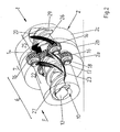
- a gear pump 1 has a housing 2 with a first housing part 2a, a middle second housing part 2b and a third housing part 2c.
- the gear pump 1 is in this case in the conveying direction F successively in an input extruder 6, a gear stage 7 and a Harmonextruder 9 divided.
- a continuous housing bore 10 is formed, in which an input screw shaft 12 is set.
- a sun gear 14 of the gear stage 7 is placed, which is in engagement with four planet gears 16.
- the planetary gears 16 are fixed to the housing 17 in rolling bearings 18 with their axes.
- the rolling bearings 18 are advantageously used in the first housing part 2a and third housing part 2c.
- transfer mixing areas 22 and 25 adjoining the gear stage 7 are formed in both the entrance extruder 6 and the exit extruder 9.
- four gears 23 and 26 extend in opposite directions to the inclination of the turns 27 and 29 of the worm shafts 12, 20 to the gear stage 7 and end in the peripheral regions of the sun gear 14 between the planet gears 16. This reduces the flight depth of the
- the number of gears 23, 26 coincides with the number of planet gears 16, each feeding gear 23, the funded material directly in front of a planetary gear sixteenth outputs.
- the material is conveyed in the circumferential direction in the second housing part 2 b and upon engagement of the toothing of the planet gear 16 in the toothing of the Sun gear 14 to a discharge passage 26 of the transfer mix region 25 of the output extruder 9 output.
- the gears of the sun gear 14 and the planetary gears 16 may be helical gears, as shown; In principle, straight teeth and, if necessary, also helical toothings can also be used for transport.
Abstract
Description
- Die Erfindung betrifft eine Zahnradpumpe, die zur Förderung hochviskoser Materialien wie z. B. Kautschukmischungen geeignet ist.
- Zahnradpumpen ermöglichen einen hohen Ausgangsdruck bei geringer Materialbelastung. Die Zahnradstufe wird hierbei oftmals in Kombination mit einer Extruderschnecke verwendet. Die DE 100 49 730 A1 zeigt eine derartige Zahnradpumpe, bei der das Material über eine Eingangsschnecke einer Zahnradstufe mit einem Planetengetriebe zugeführt wird. Das Planetengetriebe weist ein gehäusefestes Hohlrad und vier Planetenräder auf, die auf einem Planetenträger drehbar gelagert sind. Der Planetenträger ist wiederum in dem Hohlrad drehbar gelagert und weist vier sich radial von einem mittigen Grundkörper bis zur Verzahnung des Hohlrades erstreckende Trennwände auf, die um jedes Planetenrad ein sich in Förderrichtung verengendes Saugraumelement und ein sich in Förderrichtung vergrößerndes Druckraumelement ausbilden. Weiterhin ist neben dieser Ausführungsform mit verzahntem Hohlrad und unverzahntem Sonnenrad mit Planetenträger auch die als aufwändiger und komplexer eingestufte umgekehrte Anordnung mit einem verzahnten Sonnenrad und einem als Funktionsteil fungierenden Hohlrad mit mindestens einem Dichtbereich erwähnt, bei der das Hohlrad mit dem Planetenträger still stehen kann.
- Bei der Zahnradpumpe der DE 100 49 730 A1 wird durch das Planetengetriebe eine hohe Pumpleistung und Selbstreinigung erreicht. Die Lagerung der Planetenräder auf dem Planetenträger ist jedoch dann problematisch, wenn Wälzlager verwendet werden sollen, da sie nicht ausreichend abgedichtet werden können. Weiterhin erfordert der zusätzliche Planetenträger mit den Dichtwänden einen höheren Fertigungsaufwand und höhere Fertigungskosten.
- Die EP 0 642 913 B1 zeigt eine Einwellenschnecke mit einer Zahnradpumpe, die zwei sich kämmende Zahnräder aufweist, von denen eines auf die Schneckenwelle aufgesteckt ist. Die Zahnräder sind gehäusefest gelagert, wobei die Lagerstellen durch das geförderte hochviskose Material geschmiert werden. Das Pumpengehäuse ist formschlüssig mit dem Schneckengehäuse verbunden und besteht aus zwei achtförmigen Abdichtungsscheiben, die bündig an die Stirnseiten der beiden Zahnräder anschließen und mit Öffnungen für den Durchtritt der Schneckenwelle und der Achse des Gegenzahnrads versehen sind. An den Abdichtungsplatten oder am Schneckengehäuse in Höhe der Abdichtungsplatten ist je ein zum Schneckenraum hin offenes Produktdurchtrittsfenster vorgesehen. Eine derartige Zahnradpumpe ermöglicht einen Antrieb des Wellenzahnrads über die Schneckenwelle und eine gehäusefeste Lagerung des Gegenzahnrads. Der Selbstreinigungseffekt ist jedoch gering.
- Die WO 00/53390 A1 zeigt eine ähnliche Zahnradpumpe, bei der Material in radialer Richtung zwei sich kämmenden Zahnrädern zugeführt und über eine mit einem der Zahnräder verbundene Extruderschnecke abgeführt wird. Hierbei ist in einem Anfangsbereich der Extruderschnecke ein Transfermixbereich vorgesehen, in dem ein im Extrudergehäuse ausgebildeter, sich schraubenförmig und gegensinnig zur Wendelung der Schneckenwelle verlaufender Gang in seinem Querschnitt zugunsten der sich vergrößernden Schneckenwellenkammer abnimmt. Durch einen derartigen Transfermixbereich wird zusätzlich zu der Förderwirkung eine Vermischung des hochviskosen Materials bewirkt. Das Material wird von einem gemeinsamen Auslass der sich kämmenden Zahnräder in den Gang des Transfermixbereiches eingegeben und in die sich vergrößernde Schneckenwellenkammer überführt. Hierbei ist jedoch eine radiale Zuführung des zu befördernden Materials erforderlich. Weiterhin kann allenfalls eine ungenügende Selbstreinigung erreicht werden.
- Die DE 101 50 627 A1 zeigt eine Zahnradpumpe gemäß dem Oberbegriff vom Anspruch 1.
- Der Erfindung liegt die Aufgabe zugrunde, gegenüber bekannten Zahnradpumpen Verbesserungen zu schaffen und insbesondere eine gute Selbstreinigung und verschleiß- und wartungsarme Lagerung zu ermöglichen.
- Diese Aufgabe wird durch den kennzeichnenden Teil vom Anspruch 1 gelöst. Die Unteransprüche beschreiben bevorzugte Weiterbildungen.
- Erfindungsgemäß ist somit eine mindestens dreistufige Zahnradpumpe mit Zuführ- und Ausgangsschneckenstufe sowie mittlerer Zahnradstufe vorgesehen. Die mittlere Zahnradstufe ermöglicht eine hohe Förderleistung und Einstellgenauigkeit und verhindert ein Rückschlagen von Druckschwankungen des Eingangs auf die Ausgangsstufe. Die erfindungsgemäße Zahnradstufe weist gehäusefest gelagerte Planetenräder und ein mit den Schneckenwellen rotationsfest verbundenes Sonnenrad auf. Die gehäusefest gelagerten Planetenräder können - anders als in der DE 100 49 730 A1 - wartungs- und verschleißarm, insbesondere mit Wälzlagern, in dem Gehäuse gelagert werden. Durch Transfermixbereiche im Eingangs- und Ausgangsextruder wird zusätzlich zu der Förderung eine Mischung erreicht.
- Die Gänge können zur Erreichung eines größeren Querschnitts im Einlassbereich bzw. Auslassbereich über sich im wesentlichen in Umfangsrichtung erstreckende Verbindungskanäle verbunden sein.
- Die Erfindung wird im folgenden anhand der beiliegenden Zeichnungen an einer Ausführungsform erläutert. Es zeigen:
- Fig. 1 eine perspektivische Darstellung einer erfindungsgemäßen Zahnradpumpe mit geschnittenem Gehäuse;
- Fig. 2 eine der Fig. 1 entsprechende Darstellung als Durchsicht durch das Gehäuse.
- Eine Zahnradpumpe 1 weist ein Gehäuse 2 mit einem ersten Gehäuseteil 2a, einem mittleren zweiten Gehäuseteil 2b und einem dritten Gehäuseteil 2c auf. Die Zahnradpumpe 1 ist hierbei in Förderrichtung F hintereinander in einen Eingangsextruder 6, eine Zahnradstufe 7 und einen Ausgangsextruder 9 unterteilt.
- In dem Gehäuse 2 ist eine durchgängige Gehäusebohrung 10 ausgebildet, in die eine Eingangsschneckenwelle 12 gesetzt ist. Auf die Eingangsschneckenwelle 12 ist ein Sonnenrad 14 der Zahnradstufe 7 aufgesetzt, das mit vier Planetenrädern 16 in Eingriff ist. Die Planetenräder 16 sind mit ihren Achsen 17 gehäusefest in Wälzlagern 18 gelagert. Die Wälzlager 18 sind hierbei vorteilhafter Weise in dem ersten Gehäuseteil 2a bzw. dritten Gehäuseteil 2c eingesetzt. Mit dem Sonnenrad 14 und der Eingangsschneckenwelle 12 ist wiederum eine Ausgangsschneckenwelle 20 rotationsstarr verbunden.
- Erfindungsgemäß sind sowohl in dem Eingangsextruder 6 als auch dem Ausgangsextruder 9 an die Zahnradstufe 7 angrenzende Transfermixbereiche 22 und 25 ausgebildet. In den Transfermixbereichen 22 und 25 erstrecken sich vier Gänge 23 und 26 gegensinnig zur Neigung der Wendelungen 27 bzw. 29 der Schneckenwellen 12, 20 zu der Zahnradstufe 7 hin und enden in Umfangsbereichen des Sonnenrads 14 zwischen den Planetenrädern 16. Hierbei verringert sich die Gangtiefe der Eingangsschneckenwelle 12 und Ausgangsschneckenwelle 20 zu der Zahnradstufe 7 hin bei gleichzeitig zunehmendem Querschnitt der Gänge 23 und 26. Die Zahl der Gänge 23, 26 stimmt hierbei mit der Anzahl der Planetenräder 16 überein, wobei jeder zuführende Gang 23 das geförderte Material direkt vor einem Planetenrad 16 ausgibt. Das Material wird in Umfangsrichtung in dem zweiten Gehäuseteil 2b gefördert und bei Eingriff der Verzahnung des Planetenrades 16 in die Verzahnung des Sonnenrades 14 an einen abführenden Gang 26 des Transfermixbereiches 25 des Ausgangsextruders 9 ausgegeben.
- Die Verzahnungen des Sonnenrads 14 und der Planetenräder 16 können, wie gezeigt, Schrägverzahnungen sein; grundsätzlich sind hierbei auch gerade Verzahnungen und gegebenenfalls auch Pfeilverzahnungen für den Transport verwendbar.
Claims (9)
- Zahnradpumpe für hochviskose Materialien, die aufweist:ein Gehäuse (2),eine Zahnradstufe (7) mit einem Sonnenrad (14) und mehreren, gehäusefestgelagerten Planetenrädern (16),eine Eingangsschneckenstufe (6), die eine mit dem Sonnenrad (14) rotationsfestverbundene Eingangschneckenwelle (12) und einen Eingangs-Transfermixbereich (22) aufweist, undeine Ausgangsschneckenstufe (9), die eine mit dem Sonnenrad (14) rotationsfest verbundene Ausgangsschneckenwelle (20) und einen Ausgangs-Transfermixbereich (25) aufweist,wobei in dem Eingangs-Transfermixbereich (22) die Eingangsschneckenwelle (12) eine zur Zahnradstufe (7) hin abnehmende Gangtiefe aufweist,
dadurch gekennzeichnet, dass in dem Ausgangs-Transfermixbereich (25) die Ausgangsschneckenwelle (20)
eine zur Zahnradstufe (7) hin abnehmende Gangtiefe aufweist und im Gehäuse (2; 2a, 2c) gegensinnig zu den Gängen der Schneckenwellen (12, 20) verlaufende, sich zu der Zahnradstufe (7) hin im Querschnitt vergrößernde Gänge (23, 26) ausgebildet sind, die jeweils zwischen den Planetenrädern (16) enden. - Zahnradpumpe nach Anspruch 1, dadurch gekennzeichnet, dass die Planetenräder (16) in Wälzlagern (18) in dem Gehäuse (2) gelagert sind.
- Zahnradpumpe nach Anspruch 1 oder 2, dadurch gekennzeichnet, dass das Gehäuse (2) einen die Eingangsschneckenwelle (12) aufnehmenden ersten Gehäuseteil (2a), einen die Planetenräder (16) und das Sonnenrad (14) umgebenden zweiten Gehäuseteil (2b) und einen die Ausgangsschneckenwelle (20) aufnehmenden dritten Gehäuseteil (2c) aufweist.
- Zahnradpumpe nach Anspruch 2 und Anspruch 3, dadurch gekennzeichnet, dass die Wälzlager (18) der Planetenräder (16) in dem die Eingangsschneckenwelle (12) aufnehmenden ersten Gehäuseteil (2a) und dem die Ausgangsschneckenwelle (20) aufnehmenden dritten Gehäuseteil (2c) aufgenommen sind.
- Zahnradpumpe nach einem der vorherigen Ansprüche, dadurch gekennzeichnet, dass die Schneckenwellen (12, 20) miteinander rotationsfest, vorzugsweise formschlüssig, verbunden sind und das Sonnenrad (14) auf eine der Schneckenwellen (12, 20) aufgesetzt ist.
- Zahnradpumpe nach einem der vorherigen Ansprüche, dadurch gekennzeichnet, dass die Gangtiefen der Schneckenwelle (12, 20) zu der Zahnradstufe (7) hin verschwinden.
- Zahnradpumpe nach einem der vorherigen Ansprüche, dadurch gekennzeichnet, dass die Zahnradstufe (7) vier Planetenräder (16) aufweist und das Gehäuse in den die Transfermixbereichen (22, 25) jeweils vier Gänge (23, 26) aufweist.
- Zahnradpumpe nach einem der vorherigen Ansprüche, dadurch gekennzeichnet, dass im ersten Gehäuseteil (2a) und/oder im dritten Gehäuseteil (2c) Verbindungskanäle ausgebildet sind, die die Gänge (23) des Eingangs-Transfermixbereichs (22) bzw. die Gänge (26) des Ausgangs-Transfermixbereichs (25) miteinander verbinden.
- Zahnradpumpe nach einem der vorherigen Ansprüche, dadurch gekennzeichnet, dass die Gänge (23) des Eingangs-Transfermixbereichs (22) gegenüber den Gängen (26) des Ausgangs-Transfermixbereichs (25) in Umfangsrichtung beabstandet sind.
Applications Claiming Priority (2)
| Application Number | Priority Date | Filing Date | Title |
|---|---|---|---|
| DE10348985A DE10348985B3 (de) | 2003-10-22 | 2003-10-22 | Zahnradpumpe |
| PCT/EP2004/011789 WO2005039859A1 (de) | 2003-10-22 | 2004-10-19 | Zahnradpumpe |
Publications (2)
| Publication Number | Publication Date |
|---|---|
| EP1677965A1 EP1677965A1 (de) | 2006-07-12 |
| EP1677965B1 true EP1677965B1 (de) | 2007-01-10 |
Family
ID=34442170
Family Applications (1)
| Application Number | Title | Priority Date | Filing Date |
|---|---|---|---|
| EP04790614A Not-in-force EP1677965B1 (de) | 2003-10-22 | 2004-10-19 | Zahnradpumpe |
Country Status (10)
| Country | Link |
|---|---|
| US (1) | US7354188B2 (de) |
| EP (1) | EP1677965B1 (de) |
| JP (1) | JP4610564B2 (de) |
| KR (1) | KR100872610B1 (de) |
| CN (1) | CN1878652B (de) |
| CA (1) | CA2543145A1 (de) |
| DE (2) | DE10348985B3 (de) |
| ES (1) | ES2277297T3 (de) |
| RU (1) | RU2320482C2 (de) |
| WO (1) | WO2005039859A1 (de) |
Families Citing this family (14)
| Publication number | Priority date | Publication date | Assignee | Title |
|---|---|---|---|---|
| DE10348985B3 (de) * | 2003-10-22 | 2005-05-19 | Berstorff Gmbh | Zahnradpumpe |
| JP4462938B2 (ja) * | 2004-01-19 | 2010-05-12 | 株式会社ブリヂストン | ギアポンプ付押出機 |
| CA2461269A1 (en) * | 2004-03-16 | 2005-09-16 | Plastiques Gyf Ltee | Bladeless mixer |
| DE102007007824B4 (de) * | 2007-02-16 | 2012-10-25 | Vmi - Az Extrusion Gmbh | Extruder |
| DE102008023674B4 (de) | 2008-05-15 | 2012-03-22 | Ab Skf | Schmiermittelversorgungsvorrichtung |
| CN101585227B (zh) * | 2008-05-23 | 2011-04-20 | 上海龙山凤机器制造有限公司 | 行星螺杆流涎挤出机 |
| DE102008061327A1 (de) * | 2008-12-11 | 2010-06-17 | Vmi - Az Extrusion Gmbh | Extruderanordnung |
| CN102039659B (zh) * | 2009-10-15 | 2013-03-13 | 煌明机器工业股份有限公司 | 齿轮泵胶料过滤压出机 |
| US9701081B2 (en) * | 2009-12-23 | 2017-07-11 | The Goodyear Tire & Rubber Company | Method for forming stratified rubber article with variable cure rate |
| FR3013762B1 (fr) | 2013-11-27 | 2017-07-21 | Inergy Automotive Systems Res (Societe Anonyme) | Pompe pour additif |
| CN104454516B (zh) * | 2014-11-20 | 2017-01-11 | 大连华工创新科技股份有限公司 | 齿轮泵和螺杆泵组合供胶装置 |
| DE102017111275B4 (de) * | 2017-05-23 | 2020-02-13 | Gneuss Gmbh | Extruderschnecke für einen Mehrschneckenextruder für die Kunststoffextrusion und Mehrschneckenextruder |
| CN112026116B (zh) * | 2020-09-04 | 2022-04-15 | 宁波海洲机械有限公司 | 一种pet专用的注射结构 |
| US11162218B1 (en) * | 2020-09-30 | 2021-11-02 | Robert Clayton | Biomass pulp digester |
Family Cites Families (38)
| Publication number | Priority date | Publication date | Assignee | Title |
|---|---|---|---|---|
| US2767437A (en) * | 1952-02-11 | 1956-10-23 | Donald E Marshall | Method of amalgamating and extruding soap |
| US2785438A (en) * | 1954-08-18 | 1957-03-19 | Frank W Egan & Company | Plastics extruder with mixing head |
| DE2905717A1 (de) * | 1979-02-15 | 1980-08-28 | Berstorff Gmbh Masch Hermann | Einschneckenextruder zum verarbeiten und strangpressen von thermoplastischen massen |
| DE2906324C2 (de) * | 1979-02-19 | 1982-06-24 | Hermann Berstorff Maschinenbau Gmbh, 3000 Hannover | Mehrstufige Vorrichtung zum Plastifizieren und Strangpressen von plastischen Massen |
| DE2924318C2 (de) * | 1979-06-15 | 1984-07-19 | Hermann Berstorff Maschinenbau Gmbh, 3000 Hannover | Zweistufige Schneckenstrangpreßvorrichtung für thermoplastische Formmassen, insbesondere für pulverförmige Kunststoffe |
| US4336213A (en) * | 1980-02-06 | 1982-06-22 | Fox Steve A | Plastic extrusion apparatus and method |
| DE3036397A1 (de) * | 1980-09-26 | 1982-05-13 | Hermann Berstorff Maschinenbau Gmbh, 3000 Hannover | Einrichtung zum aufbereiten von pulverfoermigen kautschukmischungen |
| DE3133647A1 (de) * | 1981-08-26 | 1983-03-17 | Hermann Berstorff Maschinenbau Gmbh, 3000 Hannover | "vorrichtung zum aufbereiten von plastischen formmassen" |
| JPS641500Y2 (de) * | 1984-10-24 | 1989-01-13 | ||
| US4642040A (en) * | 1985-08-23 | 1987-02-10 | Normag Corporation | Extruder drivingly connected to gear pump |
| SU1537560A1 (ru) * | 1987-09-28 | 1990-01-23 | Киевский Политехнический Институт Им.50-Летия Великой Октябрьской Социалистической Революции | Смеситель дл полимерных материалов |
| JPH0627381Y2 (ja) * | 1988-11-10 | 1994-07-27 | 株式会社石中鉄工所 | 押出し機 |
| DE4015814C1 (de) * | 1990-05-17 | 1991-04-11 | Hermann Berstorff Maschinenbau Gmbh, 3000 Hannover, De | |
| US5267847A (en) * | 1990-12-24 | 1993-12-07 | Bridgestone Corporation | Compact precision extrusion system |
| US5378415A (en) * | 1991-04-07 | 1995-01-03 | Paul Troester Maschinenfabrik | Process for the production of homogeneous rubber blanks |
| GB2255039A (en) | 1991-04-19 | 1992-10-28 | Frenkel Ag C D | Cold feed rubber extruder construction. |
| US5304054A (en) * | 1991-04-19 | 1994-04-19 | Frenkel C-D Aktiengesellschaft | Plasticizing sections of cold feed rubber extruders |
| DE4126390A1 (de) * | 1991-08-09 | 1993-02-11 | Werner & Pfleiderer | Misch- und aufbereitungsvorrichtung mit austragspumpe |
| DE4312249C1 (de) * | 1993-04-15 | 1994-03-17 | Inventa Ag | Planetengetriebe für einen Mehrschneckenextruder |
| DE4331109A1 (de) * | 1993-09-15 | 1995-03-16 | Bayer Ag | Einwellenschnecke mit Zahnradpumpe |
| DE19614894C2 (de) * | 1996-04-16 | 1997-12-11 | Hartmut Hasse | Extrusionskopf mit Mischeinrichtung und einstellbarem Schereffekt |
| DE19703798C2 (de) * | 1997-02-01 | 2000-01-27 | Berstorff Gmbh Masch Hermann | Zahnradextruder |
| JPH11198214A (ja) * | 1997-11-17 | 1999-07-27 | Sekisui Chem Co Ltd | ゴム成形品の製造方法 |
| EP1159120A1 (de) * | 1999-03-11 | 2001-12-05 | A-Z Formen- und Maschinenbau GmbH | Einschneckenextruder |
| US6179594B1 (en) * | 1999-05-03 | 2001-01-30 | Dynisco, Inc. | Air-cooled shaft seal |
| US6468067B1 (en) * | 1999-09-16 | 2002-10-22 | Toyo Tire & Rubber Co., Ltd. | Composite extruding apparatus of rubber and method of extruding unvulcanized rubber |
| EP1320453B1 (de) * | 2000-09-28 | 2005-01-19 | Berstorff GmbH | Schneckenextruder-zahnradpumpen-anordnung für hochviskose medien |
| DE10049730A1 (de) * | 2000-09-28 | 2002-04-18 | Berstorff Gmbh | Zahnradpumpe zur Förderung hochviskoser Medien und Verwendung dieser Zahnradpumpe |
| FR2828717A1 (fr) * | 2001-08-16 | 2003-02-21 | Michelin Soc Tech | Pompe a engrenage |
| DE10150627A1 (de) * | 2001-10-12 | 2003-05-15 | Gneuss Kunststofftechnik Gmbh | Extruder zur Gewinnung von Kunststoff-Schmelzen |
| DE10154860A1 (de) * | 2001-11-08 | 2003-05-22 | Az Formen & Maschbau Gmbh | Extruderanordnung |
| DE10252368A1 (de) * | 2001-11-09 | 2003-05-22 | Barmag Barmer Maschf | Vorrichtung zum Mischen Fördern einer Polymerschmelze |
| DE10245306B4 (de) * | 2002-09-27 | 2006-03-30 | Berstorff Gmbh | Extruder/Zahnradpumpen-Kombination |
| DE10348985B3 (de) * | 2003-10-22 | 2005-05-19 | Berstorff Gmbh | Zahnradpumpe |
| US7040870B2 (en) * | 2003-12-30 | 2006-05-09 | The Goodyear Tire & Rubber Company | Gear pump with gears having curved teeth and method of feeding elastomeric material |
| JP2006247917A (ja) * | 2005-03-09 | 2006-09-21 | Toyo Tire & Rubber Co Ltd | 押出装置 |
| DE102005048847A1 (de) * | 2005-10-12 | 2007-04-19 | Vmi-Az Extrusion Gmbh | Fördervorrichtung |
| DE102005061667A1 (de) * | 2005-12-22 | 2007-07-05 | Vmi-Az Extrusion Gmbh | Planeten-Zahnradpumpe |
-
2003
- 2003-10-22 DE DE10348985A patent/DE10348985B3/de not_active Expired - Fee Related
-
2004
- 2004-10-19 ES ES04790614T patent/ES2277297T3/es active Active
- 2004-10-19 DE DE502004002648T patent/DE502004002648D1/de active Active
- 2004-10-19 US US10/576,809 patent/US7354188B2/en not_active Expired - Fee Related
- 2004-10-19 RU RU2006117358/12A patent/RU2320482C2/ru not_active IP Right Cessation
- 2004-10-19 CA CA002543145A patent/CA2543145A1/en not_active Abandoned
- 2004-10-19 CN CN2004800311931A patent/CN1878652B/zh not_active Expired - Fee Related
- 2004-10-19 KR KR1020067009820A patent/KR100872610B1/ko not_active IP Right Cessation
- 2004-10-19 WO PCT/EP2004/011789 patent/WO2005039859A1/de active Application Filing
- 2004-10-19 EP EP04790614A patent/EP1677965B1/de not_active Not-in-force
- 2004-10-19 JP JP2006536027A patent/JP4610564B2/ja not_active Expired - Fee Related
Also Published As
| Publication number | Publication date |
|---|---|
| RU2320482C2 (ru) | 2008-03-27 |
| DE10348985B3 (de) | 2005-05-19 |
| KR20060110300A (ko) | 2006-10-24 |
| CN1878652A (zh) | 2006-12-13 |
| US7354188B2 (en) | 2008-04-08 |
| EP1677965A1 (de) | 2006-07-12 |
| US20070237023A1 (en) | 2007-10-11 |
| ES2277297T3 (es) | 2007-07-01 |
| CN1878652B (zh) | 2010-12-08 |
| KR100872610B1 (ko) | 2008-12-09 |
| RU2006117358A (ru) | 2007-12-10 |
| JP4610564B2 (ja) | 2011-01-12 |
| CA2543145A1 (en) | 2005-05-06 |
| JP2007508965A (ja) | 2007-04-12 |
| WO2005039859A1 (de) | 2005-05-06 |
| DE502004002648D1 (de) | 2007-02-22 |
Similar Documents
| Publication | Publication Date | Title |
|---|---|---|
| EP0160124B1 (de) | Gleichdrall-Doppelschneckenkneter mit Knetscheiben | |
| EP1677965B1 (de) | Zahnradpumpe | |
| EP1508424B2 (de) | Schneckenmaschine mit Misch- und Knet-Scheiben | |
| DE102013021902B4 (de) | Schmelzepumpe zum Aufbau von Druck zwecks Durchdrücken von Kunststoffschmelze durch ein Werkzeug | |
| WO2004087398A2 (de) | Getriebe zum antrieb eines mehrwellenextruders, wobei das drehmoment über inneres antriebsrad und äusseres hohlrad gleichermassen eingeleitet wird | |
| EP1365906B1 (de) | Schneckenpumpe und mehrschneckenextruder mit einer solchen schneckenpumpe | |
| EP1320453B1 (de) | Schneckenextruder-zahnradpumpen-anordnung für hochviskose medien | |
| EP1801418A1 (de) | Planeten-Zahnradpumpe | |
| DE2113923A1 (de) | Mischeinrichtung fuer fluessige Kunststoffe mit Zusaetzen | |
| EP1549478B1 (de) | Extruder/zahnradpumpen-kombination | |
| EP1958757B1 (de) | Extruder | |
| DE102005048847A1 (de) | Fördervorrichtung | |
| EP0642913B1 (de) | Einwellenschnecke mit Zahnradpumpe | |
| EP2910784A1 (de) | Zweispindelige Schraubenspindelpumpe in einflutiger Bauweise | |
| EP0564884B1 (de) | Mehrwellige Schneckenmaschine mit Zahnradpumpe | |
| DE10154860A1 (de) | Extruderanordnung | |
| EP1008437A1 (de) | Getriebe für einen Doppelschneckenextruder | |
| DE10049730A1 (de) | Zahnradpumpe zur Förderung hochviskoser Medien und Verwendung dieser Zahnradpumpe | |
| EP1409223B1 (de) | Extruder-zahnradpumpen-kombination zur verwendung als einspritzeinheit in spritzgussmaschinen | |
| WO2008101904A1 (de) | Gerotorpumpe | |
| DE102014118507A1 (de) | Fördervorrichtung | |
| EP3253554A1 (de) | Stopfschnecke | |
| EP0744270A2 (de) | Mehrwellige Schneckenmaschine mit Gleich- und Gegendrallschneckenelementen | |
| DE3929707A1 (de) | Kegelzahnradpumpe | |
| WO2006027256A1 (de) | Hydraulischer zahnradmotor mit reduziertem schluckvolumen |
Legal Events
| Date | Code | Title | Description |
|---|---|---|---|
| PUAI | Public reference made under article 153(3) epc to a published international application that has entered the european phase |
Free format text: ORIGINAL CODE: 0009012 |
|
| 17P | Request for examination filed |
Effective date: 20060522 |
|
| AK | Designated contracting states |
Kind code of ref document: A1 Designated state(s): AT BE BG CH CY CZ DE DK EE ES FI FR GB GR HU IE IT LI LU MC NL PL PT RO SE SI SK TR |
|
| GRAP | Despatch of communication of intention to grant a patent |
Free format text: ORIGINAL CODE: EPIDOSNIGR1 |
|
| GRAS | Grant fee paid |
Free format text: ORIGINAL CODE: EPIDOSNIGR3 |
|
| GRAA | (expected) grant |
Free format text: ORIGINAL CODE: 0009210 |
|
| AK | Designated contracting states |
Kind code of ref document: B1 Designated state(s): AT BE BG CH CY CZ DE DK EE ES FI FR GB GR HU IE IT LI LU MC NL PL PT RO SE SI SK TR |
|
| DAX | Request for extension of the european patent (deleted) | ||
| PG25 | Lapsed in a contracting state [announced via postgrant information from national office to epo] |
Ref country code: PL Free format text: LAPSE BECAUSE OF FAILURE TO SUBMIT A TRANSLATION OF THE DESCRIPTION OR TO PAY THE FEE WITHIN THE PRESCRIBED TIME-LIMIT Effective date: 20070110 Ref country code: FI Free format text: LAPSE BECAUSE OF FAILURE TO SUBMIT A TRANSLATION OF THE DESCRIPTION OR TO PAY THE FEE WITHIN THE PRESCRIBED TIME-LIMIT Effective date: 20070110 Ref country code: IE Free format text: LAPSE BECAUSE OF FAILURE TO SUBMIT A TRANSLATION OF THE DESCRIPTION OR TO PAY THE FEE WITHIN THE PRESCRIBED TIME-LIMIT Effective date: 20070110 Ref country code: NL Free format text: LAPSE BECAUSE OF FAILURE TO SUBMIT A TRANSLATION OF THE DESCRIPTION OR TO PAY THE FEE WITHIN THE PRESCRIBED TIME-LIMIT Effective date: 20070110 Ref country code: SI Free format text: LAPSE BECAUSE OF FAILURE TO SUBMIT A TRANSLATION OF THE DESCRIPTION OR TO PAY THE FEE WITHIN THE PRESCRIBED TIME-LIMIT Effective date: 20070110 Ref country code: DK Free format text: LAPSE BECAUSE OF FAILURE TO SUBMIT A TRANSLATION OF THE DESCRIPTION OR TO PAY THE FEE WITHIN THE PRESCRIBED TIME-LIMIT Effective date: 20070110 |
|
| REG | Reference to a national code |
Ref country code: GB Ref legal event code: FG4D Free format text: NOT ENGLISH |
|
| REG | Reference to a national code |
Ref country code: IE Ref legal event code: FG4D Free format text: LANGUAGE OF EP DOCUMENT: GERMAN |
|
| REF | Corresponds to: |
Ref document number: 502004002648 Country of ref document: DE Date of ref document: 20070222 Kind code of ref document: P |
|
| REG | Reference to a national code |
Ref country code: CH Ref legal event code: NV Representative=s name: KIRKER & CIE SA |
|
| GBT | Gb: translation of ep patent filed (gb section 77(6)(a)/1977) |
Effective date: 20070308 |
|
| PG25 | Lapsed in a contracting state [announced via postgrant information from national office to epo] |
Ref country code: SE Free format text: LAPSE BECAUSE OF FAILURE TO SUBMIT A TRANSLATION OF THE DESCRIPTION OR TO PAY THE FEE WITHIN THE PRESCRIBED TIME-LIMIT Effective date: 20070410 Ref country code: BG Free format text: LAPSE BECAUSE OF FAILURE TO SUBMIT A TRANSLATION OF THE DESCRIPTION OR TO PAY THE FEE WITHIN THE PRESCRIBED TIME-LIMIT Effective date: 20070410 |
|
| ET | Fr: translation filed | ||
| PG25 | Lapsed in a contracting state [announced via postgrant information from national office to epo] |
Ref country code: PT Free format text: LAPSE BECAUSE OF FAILURE TO SUBMIT A TRANSLATION OF THE DESCRIPTION OR TO PAY THE FEE WITHIN THE PRESCRIBED TIME-LIMIT Effective date: 20070611 |
|
| REG | Reference to a national code |
Ref country code: ES Ref legal event code: FG2A Ref document number: 2277297 Country of ref document: ES Kind code of ref document: T3 |
|
| NLV1 | Nl: lapsed or annulled due to failure to fulfill the requirements of art. 29p and 29m of the patents act | ||
| REG | Reference to a national code |
Ref country code: IE Ref legal event code: FD4D |
|
| PLBE | No opposition filed within time limit |
Free format text: ORIGINAL CODE: 0009261 |
|
| STAA | Information on the status of an ep patent application or granted ep patent |
Free format text: STATUS: NO OPPOSITION FILED WITHIN TIME LIMIT |
|
| 26N | No opposition filed |
Effective date: 20071011 |
|
| PG25 | Lapsed in a contracting state [announced via postgrant information from national office to epo] |
Ref country code: RO Free format text: LAPSE BECAUSE OF FAILURE TO SUBMIT A TRANSLATION OF THE DESCRIPTION OR TO PAY THE FEE WITHIN THE PRESCRIBED TIME-LIMIT Effective date: 20070110 |
|
| BERE | Be: lapsed |
Owner name: BERSTORFF G.M.B.H. Effective date: 20071031 Owner name: VMI - AZ EXTRUSION G.M.B.H. Effective date: 20071031 |
|
| PG25 | Lapsed in a contracting state [announced via postgrant information from national office to epo] |
Ref country code: GR Free format text: LAPSE BECAUSE OF FAILURE TO SUBMIT A TRANSLATION OF THE DESCRIPTION OR TO PAY THE FEE WITHIN THE PRESCRIBED TIME-LIMIT Effective date: 20070411 |
|
| PG25 | Lapsed in a contracting state [announced via postgrant information from national office to epo] |
Ref country code: MC Free format text: LAPSE BECAUSE OF NON-PAYMENT OF DUE FEES Effective date: 20071031 |
|
| PG25 | Lapsed in a contracting state [announced via postgrant information from national office to epo] |
Ref country code: BE Free format text: LAPSE BECAUSE OF NON-PAYMENT OF DUE FEES Effective date: 20071031 |
|
| PG25 | Lapsed in a contracting state [announced via postgrant information from national office to epo] |
Ref country code: EE Free format text: LAPSE BECAUSE OF FAILURE TO SUBMIT A TRANSLATION OF THE DESCRIPTION OR TO PAY THE FEE WITHIN THE PRESCRIBED TIME-LIMIT Effective date: 20070110 |
|
| PG25 | Lapsed in a contracting state [announced via postgrant information from national office to epo] |
Ref country code: CY Free format text: LAPSE BECAUSE OF FAILURE TO SUBMIT A TRANSLATION OF THE DESCRIPTION OR TO PAY THE FEE WITHIN THE PRESCRIBED TIME-LIMIT Effective date: 20070110 |
|
| PG25 | Lapsed in a contracting state [announced via postgrant information from national office to epo] |
Ref country code: LU Free format text: LAPSE BECAUSE OF NON-PAYMENT OF DUE FEES Effective date: 20071019 |
|
| PG25 | Lapsed in a contracting state [announced via postgrant information from national office to epo] |
Ref country code: TR Free format text: LAPSE BECAUSE OF FAILURE TO SUBMIT A TRANSLATION OF THE DESCRIPTION OR TO PAY THE FEE WITHIN THE PRESCRIBED TIME-LIMIT Effective date: 20070110 Ref country code: HU Free format text: LAPSE BECAUSE OF FAILURE TO SUBMIT A TRANSLATION OF THE DESCRIPTION OR TO PAY THE FEE WITHIN THE PRESCRIBED TIME-LIMIT Effective date: 20070711 |
|
| PGFP | Annual fee paid to national office [announced via postgrant information from national office to epo] |
Ref country code: FR Payment date: 20121203 Year of fee payment: 9 Ref country code: CZ Payment date: 20121015 Year of fee payment: 9 Ref country code: CH Payment date: 20121115 Year of fee payment: 9 |
|
| PGFP | Annual fee paid to national office [announced via postgrant information from national office to epo] |
Ref country code: GB Payment date: 20121025 Year of fee payment: 9 Ref country code: ES Payment date: 20121127 Year of fee payment: 9 Ref country code: SK Payment date: 20121017 Year of fee payment: 9 |
|
| PGFP | Annual fee paid to national office [announced via postgrant information from national office to epo] |
Ref country code: AT Payment date: 20121031 Year of fee payment: 9 |
|
| REG | Reference to a national code |
Ref country code: DE Ref legal event code: R082 Ref document number: 502004002648 Country of ref document: DE Representative=s name: SPLANEMANN PATENTANWAELTE PARTNERSCHAFT, DE |
|
| REG | Reference to a national code |
Ref country code: CH Ref legal event code: PUE Owner name: TKH DEUTSCHLAND GMBH AND CO. KG, DE Free format text: FORMER OWNER: BERSTORFF GMBH, DE |
|
| REG | Reference to a national code |
Ref country code: DE Ref legal event code: R081 Ref document number: 502004002648 Country of ref document: DE Owner name: TKH DEUTSCHLAND GMBH & CO. KG, DE Free format text: FORMER OWNER: KRAUSSMAFFEI BERSTORFF GMBH, VMI-AZ EXTRUSION GMBH, , DE Effective date: 20130422 Ref country code: DE Ref legal event code: R082 Ref document number: 502004002648 Country of ref document: DE Representative=s name: SPLANEMANN PATENTANWAELTE PARTNERSCHAFT, DE Effective date: 20130422 Ref country code: DE Ref legal event code: R081 Ref document number: 502004002648 Country of ref document: DE Owner name: TKH DEUTSCHLAND GMBH & CO. KG, DE Free format text: FORMER OWNERS: KRAUSSMAFFEI BERSTORFF GMBH, 30625 HANNOVER, DE; VMI-AZ EXTRUSION GMBH, 93486 RUNDING, DE Effective date: 20130422 |
|
| REG | Reference to a national code |
Ref country code: FR Ref legal event code: TQ Owner name: VMI - AZ EXTRUSION GMBH, DE Effective date: 20130701 Ref country code: FR Ref legal event code: TQ Owner name: TKH DEUTSCHLAND GMBH & CO. KG, DE Effective date: 20130701 |
|
| REG | Reference to a national code |
Ref country code: FR Ref legal event code: TP Owner name: TKH DEUTSCHLAND GMBH & CO. KG, DE Effective date: 20130724 |
|
| REG | Reference to a national code |
Ref country code: SK Ref legal event code: PC4A Ref document number: E 2120 Country of ref document: SK Owner name: TKH DEUTSCHLAND GMBH & CO. KG, RUNDING, DE Free format text: FORMER OWNER: BERSTORFF GMBH, HANNOVER, DE; VMI - AZ EXTRUSION GMBH, MUENCHEN, DE Effective date: 20130222 |
|
| REG | Reference to a national code |
Ref country code: GB Ref legal event code: 732E Free format text: REGISTERED BETWEEN 20130912 AND 20130918 |
|
| REG | Reference to a national code |
Ref country code: GB Ref legal event code: 732E Free format text: REGISTERED BETWEEN 20130919 AND 20130925 |
|
| REG | Reference to a national code |
Ref country code: CH Ref legal event code: PL |
|
| REG | Reference to a national code |
Ref country code: AT Ref legal event code: MM01 Ref document number: 351087 Country of ref document: AT Kind code of ref document: T Effective date: 20131019 |
|
| GBPC | Gb: european patent ceased through non-payment of renewal fee |
Effective date: 20131019 |
|
| REG | Reference to a national code |
Ref country code: SK Ref legal event code: MM4A Ref document number: E 2120 Country of ref document: SK Effective date: 20131019 |
|
| PG25 | Lapsed in a contracting state [announced via postgrant information from national office to epo] |
Ref country code: LI Free format text: LAPSE BECAUSE OF NON-PAYMENT OF DUE FEES Effective date: 20131031 Ref country code: CH Free format text: LAPSE BECAUSE OF NON-PAYMENT OF DUE FEES Effective date: 20131031 Ref country code: GB Free format text: LAPSE BECAUSE OF NON-PAYMENT OF DUE FEES Effective date: 20131019 |
|
| REG | Reference to a national code |
Ref country code: FR Ref legal event code: ST Effective date: 20140630 |
|
| PG25 | Lapsed in a contracting state [announced via postgrant information from national office to epo] |
Ref country code: FR Free format text: LAPSE BECAUSE OF NON-PAYMENT OF DUE FEES Effective date: 20131031 Ref country code: CZ Free format text: LAPSE BECAUSE OF NON-PAYMENT OF DUE FEES Effective date: 20131019 Ref country code: SK Free format text: LAPSE BECAUSE OF NON-PAYMENT OF DUE FEES Effective date: 20131019 Ref country code: AT Free format text: LAPSE BECAUSE OF NON-PAYMENT OF DUE FEES Effective date: 20131019 |
|
| REG | Reference to a national code |
Ref country code: ES Ref legal event code: FD2A Effective date: 20141107 |
|
| PG25 | Lapsed in a contracting state [announced via postgrant information from national office to epo] |
Ref country code: ES Free format text: LAPSE BECAUSE OF NON-PAYMENT OF DUE FEES Effective date: 20131020 |
|
| PGFP | Annual fee paid to national office [announced via postgrant information from national office to epo] |
Ref country code: DE Payment date: 20140820 Year of fee payment: 11 |
|
| PGFP | Annual fee paid to national office [announced via postgrant information from national office to epo] |
Ref country code: IT Payment date: 20141022 Year of fee payment: 11 |
|
| REG | Reference to a national code |
Ref country code: DE Ref legal event code: R119 Ref document number: 502004002648 Country of ref document: DE |
|
| PG25 | Lapsed in a contracting state [announced via postgrant information from national office to epo] |
Ref country code: DE Free format text: LAPSE BECAUSE OF NON-PAYMENT OF DUE FEES Effective date: 20160503 Ref country code: IT Free format text: LAPSE BECAUSE OF NON-PAYMENT OF DUE FEES Effective date: 20151019 |