EP1677327A1 - Energieversorgungssystem für Startvorrichtung - Google Patents
Energieversorgungssystem für Startvorrichtung Download PDFInfo
- Publication number
- EP1677327A1 EP1677327A1 EP05110884A EP05110884A EP1677327A1 EP 1677327 A1 EP1677327 A1 EP 1677327A1 EP 05110884 A EP05110884 A EP 05110884A EP 05110884 A EP05110884 A EP 05110884A EP 1677327 A1 EP1677327 A1 EP 1677327A1
- Authority
- EP
- European Patent Office
- Prior art keywords
- circuit breaker
- supply system
- power supply
- energy
- starting device
- Prior art date
- Legal status (The legal status is an assumption and is not a legal conclusion. Google has not performed a legal analysis and makes no representation as to the accuracy of the status listed.)
- Granted
Links
Images

Classifications
-
- F—MECHANICAL ENGINEERING; LIGHTING; HEATING; WEAPONS; BLASTING
- F02—COMBUSTION ENGINES; HOT-GAS OR COMBUSTION-PRODUCT ENGINE PLANTS
- F02N—STARTING OF COMBUSTION ENGINES; STARTING AIDS FOR SUCH ENGINES, NOT OTHERWISE PROVIDED FOR
- F02N11/00—Starting of engines by means of electric motors
- F02N11/08—Circuits specially adapted for starting of engines
- F02N11/0862—Circuits specially adapted for starting of engines characterised by the electrical power supply means, e.g. battery
-
- B—PERFORMING OPERATIONS; TRANSPORTING
- B60—VEHICLES IN GENERAL
- B60K—ARRANGEMENT OR MOUNTING OF PROPULSION UNITS OR OF TRANSMISSIONS IN VEHICLES; ARRANGEMENT OR MOUNTING OF PLURAL DIVERSE PRIME-MOVERS IN VEHICLES; AUXILIARY DRIVES FOR VEHICLES; INSTRUMENTATION OR DASHBOARDS FOR VEHICLES; ARRANGEMENTS IN CONNECTION WITH COOLING, AIR INTAKE, GAS EXHAUST OR FUEL SUPPLY OF PROPULSION UNITS IN VEHICLES
- B60K28/00—Safety devices for propulsion-unit control, specially adapted for, or arranged in, vehicles, e.g. preventing fuel supply or ignition in the event of potentially dangerous conditions
- B60K28/10—Safety devices for propulsion-unit control, specially adapted for, or arranged in, vehicles, e.g. preventing fuel supply or ignition in the event of potentially dangerous conditions responsive to conditions relating to the vehicle
- B60K28/14—Safety devices for propulsion-unit control, specially adapted for, or arranged in, vehicles, e.g. preventing fuel supply or ignition in the event of potentially dangerous conditions responsive to conditions relating to the vehicle responsive to accident or emergency, e.g. deceleration, tilt of vehicle
-
- F—MECHANICAL ENGINEERING; LIGHTING; HEATING; WEAPONS; BLASTING
- F02—COMBUSTION ENGINES; HOT-GAS OR COMBUSTION-PRODUCT ENGINE PLANTS
- F02N—STARTING OF COMBUSTION ENGINES; STARTING AIDS FOR SUCH ENGINES, NOT OTHERWISE PROVIDED FOR
- F02N11/00—Starting of engines by means of electric motors
- F02N11/10—Safety devices
-
- H—ELECTRICITY
- H01—ELECTRIC ELEMENTS
- H01H—ELECTRIC SWITCHES; RELAYS; SELECTORS; EMERGENCY PROTECTIVE DEVICES
- H01H51/00—Electromagnetic relays
- H01H51/02—Non-polarised relays
- H01H51/04—Non-polarised relays with single armature; with single set of ganged armatures
- H01H51/06—Armature is movable between two limit positions of rest and is moved in one direction due to energisation of an electromagnet and after the electromagnet is de-energised is returned by energy stored during the movement in the first direction, e.g. by using a spring, by using a permanent magnet, by gravity
- H01H51/065—Relays having a pair of normally open contacts rigidly fixed to a magnetic core movable along the axis of a solenoid, e.g. relays for starting automobiles
-
- F—MECHANICAL ENGINEERING; LIGHTING; HEATING; WEAPONS; BLASTING
- F02—COMBUSTION ENGINES; HOT-GAS OR COMBUSTION-PRODUCT ENGINE PLANTS
- F02N—STARTING OF COMBUSTION ENGINES; STARTING AIDS FOR SUCH ENGINES, NOT OTHERWISE PROVIDED FOR
- F02N11/00—Starting of engines by means of electric motors
- F02N11/08—Circuits specially adapted for starting of engines
- F02N11/087—Details of the switching means in starting circuits, e.g. relays or electronic switches
-
- H—ELECTRICITY
- H01—ELECTRIC ELEMENTS
- H01H—ELECTRIC SWITCHES; RELAYS; SELECTORS; EMERGENCY PROTECTIVE DEVICES
- H01H1/00—Contacts
- H01H1/58—Electric connections to or between contacts; Terminals
- H01H2001/5877—Electric connections to or between contacts; Terminals with provisions for direct mounting on a battery pole
-
- H—ELECTRICITY
- H01—ELECTRIC ELEMENTS
- H01H—ELECTRIC SWITCHES; RELAYS; SELECTORS; EMERGENCY PROTECTIVE DEVICES
- H01H50/00—Details of electromagnetic relays
- H01H50/54—Contact arrangements
- H01H50/60—Contact arrangements moving contact being rigidly combined with movable part of magnetic circuit
Definitions
- a power supply system for starting devices which consists of an energy storage and a starting device which is connected to the energy storage means of a power supply line.
- the power supply line can be interrupted by means of a circuit breaker.
- the circuit breaker is attached to the energy storage or very close to the energy storage.
- the circuit breaker itself is described as being ignited, operated gasgeneratorisch switch that sets an irreversible separation process in motion. The disadvantage of this system is that after a separation of the switch must be replaced.
- the erfmdungssiee power supply system having the features of the main claim has the advantage that on the one hand the disconnect switch can always be activated when the starting device is not needed.
- the starting device which is normally located in the crash region of a vehicle, can be reversibly de-energized at any time when the starting device is not used as intended. In the event of an accident, there is therefore no risk of electric shock or other hazards that may occur in connection with high currents. Also at workshop visits or repairs to the vehicle, the risk of short circuits is no longer given.
- disconnect switch is completely seated in the battery pole. It is particularly simple and cost-effective to realize a reversible disconnecting switch by means of an electromagnetic switch.
- a circuit breaker results in a particularly compact design when the circuit breaker has a magnetic circuit surrounding a battery terminal.
- circuit breaker has a contact bridge, which is provided for connecting a double contact. This design ensures that between the starting device and the energy storage two separation points are to be bridged. This leads to a particularly safe separation.
- a busbar holding the circuit breaker is attached to the battery pole terminal.
- FIG. 1 a shows a power supply system 10 for starting devices 13.
- This energy supply system 10 has, in addition to the starting device 13, an energy store 16 which, for example, can be designed as a possible starter battery.
- a power supply line 19 is arranged, which supplies the starting device 13 with electrical energy as a "starter cable”.
- a circuit breaker 22 is arranged, which is designed as a reversible disconnector 22 and is disposed directly on the energy storage 16.
- the circuit breaker 22 has a contact bridge 25, by means of which two unspecified here contacts are electrically connected in order to set the starting device 13 in operation can.
- the circuit breaker 22 or the contact bridge 25 is by means of an armature 28 which is actuated by an electromagnetically operating coil 31, movable. In the case of actuation, a coil voltage U S is applied to the coil 31.
- the starting device 13 shown in FIG. 1a may be, for example, a starter operating on the principle of inertia, which does not require an engagement relay.
- FIG. 1b is a somewhat more detailed illustrated power supply system 10 for conventional starting devices 13 (push-screw starter) represents.
- the disconnecting switch 22 or its coil 31 is energized by an ignition / start switch or start control device.
- both the "terminal 30" which usually supplies the starter motor with power, as well as the "terminal 50”, which energizes a contactor 32.
- a feed coil EW and a holding coil HW are arranged.
- FIG 1c is a slightly modified from the representation of Figure 1b power supply system 10 for conventional starting devices 13 (push-screw starter) represents.
- the disconnecting switch 22 or its coil 31 is energized by an ignition / start switch or start control device.
- the contact bridge 25 By means of the contact bridge 25, only the “terminal 30" is supplied with power current.
- the "terminal 50" is energized directly by an ignition / starter switch or starter control unit.
- the circuit breaker 22 is designed here as a so-called hinged armature relay 34.
- the circuit breaker 22 sits here in a battery pole 37, as they are usually present in battery covers 40.
- Batteriepolwanne 37 sits the battery terminal 43, to which the circuit breaker 22 is attached.
- the circuit breaker 22 is adapted in size to the battery pole 37 and here also sits completely in the battery pole 37.
- the circuit breaker 22 has a magnetic circuit 46 which surrounds the battery pole 43.
- a core 49 which is surrounded by the coil 31, belongs to this electromagnetic circuit 46.
- this includes a bracket 52, which represents an immediate electromagnetic extension of the core 49.
- a hinged armature 55 which is used by turning on the coil 31 and the structure of the electromagnetic field in the electromagnetic circuit 46 to the core 49.
- two double contacts 56 are electrically conductively connected to each other. Since the power supply line 19 is connected to one of the two double contacts 56, then the starting device 13 is energized.
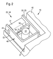
- the lower in Figure 2 of the two double contacts 56 corresponds to the load busbar 70 of the terminal 30, as it is usually referred to standard.
- the circuit breaker 22 On the busbar 70, the circuit breaker 22 is held and fixed. This terminal 30 serves both for the mechanical attachment of the circuit breaker 22 and for the electrical, direct contacting of the circuit breaker 22 with the energy storage 16.
- the second double contact 56 which is arranged above the first double contact 56, corresponds to the so-called terminal 45 as a load current rail, This is a standard corresponding designation.
- This "clamp 45" is led outwards in isolation.
- the power supply line 19 is screwed or otherwise secured, so that this power supply line 19 is tension-free with the hinged armature 55 open. If the coil 31 is energized via a drive signal (terminal 50), the hinged armature 55 pulls on and closes the main contact.
- the starting device 13 is energized and the starting process can take place.
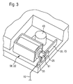
- FIG. 3 shows a second exemplary embodiment of a circuit breaker 22. Also, this circuit breaker 22 is adapted to the battery pole 37, as described above.
- the Tauchankerrelais 58 shown in Figure 3 works in a similar manner as the Klappankerrelais 34.
- the Tauchankerrelais 58 in turn has a coil 31, in the center of an armature 61 is slidably mounted. At the free, outside the Coil 31 lying the end of the armature 61 is a contact bridge 25. On both sides of the contact bridge 25, the double contacts 55 are arranged, wherein the energy storage 16 directed double contact 55 is formed as a busbar 70 to which the circuit breaker 22 is held and fixed.
- the other double contact 55 is arranged, to which the power supply line 19 is attached.
- the function of this Tauchankerrelais 58 is the same as the hinged armature relay 34. If the relay 58 receives a drive signal (terminal 50), the double contacts 55 are closed via the contact bridge 25 and the starter 13 is energized.
Landscapes
- Engineering & Computer Science (AREA)
- Chemical & Material Sciences (AREA)
- Combustion & Propulsion (AREA)
- Mechanical Engineering (AREA)
- General Engineering & Computer Science (AREA)
- Physics & Mathematics (AREA)
- Electromagnetism (AREA)
- Transportation (AREA)
- Connection Of Motors, Electrical Generators, Mechanical Devices, And The Like (AREA)
Abstract
Description
- Aus der deutschen Offenlegungsschrift 196 06 450 A1 ist ein Energieversorgungssystem für Startvorrichtungen bekannt, das aus einem Energiespeicher und einer Startvorrichtung besteht, die mit dem Energiespeicher mittels einer Energieversorgungsleitung verbunden ist. Die Energieversorgungsleitung kann mittels eines Trennschalters unterbrochen werden. Der Trennschalter ist am Energiespeicher oder sehr nahe am Energiespeicher befestigt. Der Trennschalter selbst ist als zu zündender, gasgeneratorisch betriebener Schalter beschrieben, der einen irreversiblen Trennprozess in Gang setzt. Nachteilig ist bei diesem System, dass nach einer Trennung der Schalter ausgetauscht werden muss.
- Das erfmdungsgemäße Energieversorgungssystem mit den Merkmalen des Hauptanspruchs hat den Vorteil, dass einerseits der Trennschalter immer dann aktiviert werden kann, wenn die Startvorrichtung nicht benötigt wird. Dadurch kann die sich üblicherweise im Crashbereich eines Fahrzeugs befindliche Startvorrichtung zu jedem Zeitpunkt, in dem die Startvorrichtung nicht bestimmungsgemäß benötigt wird, reversibel spannungsfrei geschaltet werden. Bei einem Unfall besteht somit von vomeherein nicht die Gefahr eines Stromschlags oder sonstige Gefährdungen, die im Zusammenhang mit hohen Stromstärken auftreten können. Auch bei Werkstattbesuchen bzw. Reparaturen am Fahrzeug ist die Gefahr von Kurzschlüssen nicht mehr gegeben.
- Durch die in den Unteransprüchen aufgeführten Maßnahmen sind vorteilhafte Weiterbildungen des Energieversorgungssystems nach dem Hauptanspruch möglich. Besonders unauffällig und keinen unnötigen Platz verbrauchend ist das System dann, wenn der Trennschalter größenmäßig an eine Batteriepolwanne angepasst ist.
- Besonders vorteilhaft ist es, wenn der Trennschalter vollständig in der Batteriepolwanne sitzt. Besonders einfach und kostengünstig lässt sich ein reversibler Trennschalter durch einen elektromagnetischen Schalter verwirklichen.
- Gemäß einem Ausführungsbeispiel eines Trennschalters ergibt sich eine besonders kompakte Bauform dann, wenn der Trennschalter einen magnetischen Kreis hat, der eine Batteriepolklemme umgibt.
- Es ist des Weiteren vorgesehen, dass der Trennschalter eine Kontaktbrücke hat, die zur Verbindung eines Doppelkontakts vorgesehen ist. Durch diese Ausbildung ist sichergestellt, dass zwischen der Startvorrichtung und dem Energiespeicher zwei Trennstellen zu überbrücken sind. Dies führt zu einem besonders sicheren Trennen.
- Nach einer weiteren Ausgestaltung ist vorgesehen, dass an der Batteriepolklemme eine den Trennschalter haltende Stromschiene befestigt ist. Durch diese Art des Befestigens sind weitere Halteelemente nicht erforderlich, um den Trennschalter ortsfest zu befestigen.
- In den Zeichnungen sind Ausführungsbeispiele eines erfmdungsgemäße Energieversorgungssystems für Startvorrichtungen dargestellt. Es zeigen:
- Figur 1a
- bis
- Figur 1c
- schematische Darstellungen eines Energieversorgungssystems,
- Figur 2
- eine räumliche Ansicht auf einen ersten Trennschalter,
- Figur 3
- eine räumliche Ansicht auf ein zweites Ausführungsbeispiel eines Trennschalters.
- In Figur 1a ist ein Energieversorgungssystem 10 für Startvorrichtungen 13 darstellt. Dieses Energieversorgungssystem 10 weist neben der Startvorrichtung 13 einen Energiespeicher 16 auf, der bspw. als mögliche Starterbatterie ausgebildet sein kann. Zwischen dem Energiespeicher 16 und der Startvorrichtung 13 ist eine Energieversorgungsleitung 19 angeordnet, die als "Starterkabel" die Startvorrichtung 13 mit elektrischer Energie versorgt. Zwischen dem Energiespeicher 16 und der Startvorrichtung 13 ist ein Trennschalter 22 angeordnet, der als reversibler Trennschalter 22 ausgeführt ist und unmittelbar am Energiespeicher 16 angeordnet ist. Der Trennschalter 22 weist eine Kontaktbrücke 25 auf, mittels derer zwei hier nicht näher bezeichnete Kontakte elektrisch verbindbar sind, um die Startvorrichtung 13 in Betrieb setzten zu können. Der Trennschalter 22 bzw. die Kontaktbrücke 25 ist mittels eines Ankers 28, der durch eine elektromagnetisch arbeitende Spule 31 betätigbar ist, bewegbar. Im Betätigungsfall liegt an der Spule 31 eine Spulenspannung US an. Die in Figur 1a dargestellte Startvorrichtung 13 kann beispielsweise als ein nach dem Trägheitsprinzip arbeitender Starter sein, der ohne Einrückrelais auskommt.
- In Figur 1b ist ein etwas detaillierter dargestelltes Energieversorgungssystem 10 für konventionelle Startvorrichtungen 13 (Schub-Schraubtrieb-Starter) darstellt. Gemäß dieser Darstellung wird der Trennschalter 22 bzw. dessen Spule 31 von einem Zünd-/Startschalter bzw. Startsteuergerät bestromt. Mittels der Kontaktbrücke 25 wird sowohl die "Klemme 30", welche den Startermotor üblicherweise mit Leistungsstrom versorgt, als auch die "Klemme 50", die ein Einrückrelais 32 bestromt. Im Einrückrelais 32 sind eine Einzugsspule EW und eine Haltespule HW angeordnet.
- In Figur 1c ein von der Darstellung nach Figur 1b leicht modifiziertes Energieversorgungssystem 10 für konventionelle Startvorrichtungen 13 (Schub-Schraubtrieb-Starter) darstellt. Gemäß dieser Darstellung wird der Trennschalter 22 bzw. dessen Spule 31 von einem Zünd-/Startschalter bzw. Startsteuergerät bestromt. Mittels der Kontaktbrücke 25 wird nur die "Klemme 30" mit Leistungsstrom versorgt. Die "Klemme 50" wird direkt von einem Zünd-/Startschalter bzw. Startsteuergerät bestromt.
- In Figur 2 ist ein erstes Ausführungsbeispiel eines Trennschalters 22 dargestellt. Der Trennschalter 22 ist hier als so genanntes Klappankerrelais 34 ausgebildet. Der Trennschalter 22 sitzt hier in einer Batteriepolwanne 37, wie sie üblicherweise bei Batteriedeckeln 40 vorhanden sind. In dieser Batteriepolwanne 37 sitzt die Batteriepolklemme 43, an der der Trennschalter 22 befestigt ist. Der Trennschalter 22 ist größenmäßig an die Batteriepolwanne 37 angepasst und sitzt hier auch vollständig in der Batteriepolwanne 37. Zur optimalen Ausnutzung der Batteriepolwanne 37 ist hier vorgesehen, dass der Trennschalter 22 einen magnetischen Kreis 46 hat, der die Batteriepolklemme 43 umgibt. Zu diesem elektromagnetischen Kreis 46 gehört hier bspw. ein Kern 49, der von der Spule 31 umgeben ist. Des Weiteren gehört hierzu ein Bügel 52, der eine unmittelbare elektromagnetische Verlängerung des Kerns 49 darstellt. Von diesem Bügel 52 geht letztlich ein Klappanker 55 aus, der durch das Einschalten der Spule 31 und den Aufbau des elektromagnetischen Feldes im elektromagnetischen Kreis 46 an den Kern 49 herangezogen wird. Durch diese Verlagerung des Klappankers 55, der übrigens der Kontaktbrücke 25 entspricht, werden zwei Doppelkontakte 56 elektrisch leitfähig miteinander verbunden. Da mit einem der beiden Doppelkontakte 56 die Energieversorgungsleitung 19 verbunden ist, wird dann die Startvorrichtung 13 bestromt. Der in Figur 2 untere der beiden Doppelkontakte 56 entspricht als Laststromschiene 70 der Klemme 30, wie sie üblicherweise normgerecht bezeichnet wird. An der Stromschiene 70 ist der Trennschalter 22 gehalten und befestigt. Diese Klemme 30 dient hier sowohl zur mechanischen Befestigung des Trennschalters 22 als auch zur elektrischen, direkten Kontaktierung des Trennschalters 22 mit dem Energiespeicher 16. Der zweite Doppelkontakt 56, welcher über dem ersten Doppelkontakt 56 angeordnet ist, entspricht als Laststromschiene der so genannten Klemme 45, auch diese ist eine normentsprechende Bezeichnung. Diese "Klemme 45" wird isoliert nach außen geführt. An diese Laststromschiene (Klemme 45) wird die Energieversorgungsleitung 19 geschraubt oder anderweitig befestigt, sodass diese Energieversorgungsleitung 19 bei geöffnetem Klappanker 55 spannungsfrei ist. Wird die Spule 31 über ein Ansteuersignal (Klemme 50) bestromt, zieht der Klappanker 55 an und schließt den Hauptkontakt. Die Startvorrichtung 13 wird bestromt und der Startvorgang kann stattfinden.
- In Figur 3 ist ein zweites Ausführungsbeispiel für einen Trennschalter 22 dargestellt. Auch dieser Trennschalter 22 ist an die Batteriepolwanne 37, wie zuvor beschrieben, angepasst. Das in Figur 3 dargestellte Tauchankerrelais 58 funktioniert auf ähnliche Weise wie das Klappankerrelais 34. Das Tauchankerrelais 58 weist wiederum eine Spule 31 auf, in deren Zentrum ein Anker 61 verschiebbar gelagert ist. An dem freien, außerhalb der Spule 31 liegenden Ende des Ankers 61 befindet sich eine Kontaktbrücke 25. Beiderseits der Kontaktbrücke 25 sind die Doppelkontakte 55 angeordnet, wobei der zum Energiespeicher 16 gerichtete Doppelkontakt 55 als Stromschiene 70 ausgebildet ist, an der der Trennschalter 22 gehalten und befestigt ist. Auf der anderen Seite der Kontaktbrücke 25 und somit in Richtung zur Startvorrichtung 13 ist der andere Doppelkontakt 55 angeordnet, an den die Energieversorgungsleitung 19 befestigt ist. Die Funktion dieses Tauchankerrelais 58 ist die gleiche wie beim Klappankerrelais 34. Bekommt das Relais 58 ein Ansteuersignal (Klemme 50), so werden die Doppelkontakte 55 über die Kontaktbrücke 25 geschlossen und die Startvorrichtung 13 bestromt.
Claims (9)
- Energieversorgungssystem für Startvorrichtungen, mit einem Energiespeicher (16) und einer Startvorrichtung (13), die von dem Energiespeicher (16) mit elektrischer Energie versorgbar ist, mit einer Energieversorgungsleitung (19), welche die elektrische Energie vom Energiespeicher (16) zur Startvorrichtung (13) leitet, mit einem Trennschalter (22) zwischen dem Energiespeicher (16) und der Startvorrichtung (13), dadurch gekennzeichnet, dass der Trennschalter (22) reversibel und unmittelbar am Energiespeicher (16) angeordnet ist.
- Energieversorgungssystem nach Anspruch 1, dadurch gekennzeichnet, dass der Trennschalter (22) größenmäßig an eine Batteriepolwanne (37) angepasst ist.
- Energieversorgungssystem nach Anspruch 2, dadurch gekennzeichnet, dass der Trennschalter (22) vollständig in der Batteriepolwanne (37) sitzt.
- Energieversorgungssystem nach einem der vorstehenden Ansprüche, dadurch gekennzeichnet, dass der Trennschalter (22) ein elektromagnetischer Schalter ist.
- Energieversorgungssystem nach Anspruch 4, dadurch gekennzeichnet, dass der Trennschalter (22) einen magnetischen Kreis (46) hat, der eine Batteriepolklemme (43) umgibt.
- Energieversorgungssystem nach Anspruch 5, dadurch gekennzeichnet, dass der Trennschalter (22) ein Klappankerrelais (34) ist.
- Energieversorgungssystem nach Anspruch 4, dadurch gekennzeichnet, dass der Trennschalter (22) ein Tauchankerrelais (58) ist.
- Energieversorgungssystem nach einem der Ansprüche 4 bis 7, dadurch gekennzeichnet, dass der Trennschalter (22) eine Kontaktbrücke (25) hat, die zur Verbindung eines Doppelkontakts (55) vorgesehen ist.
- Energieversorgungssystem nach einem der vorstehenden Ansprüche, dadurch gekennzeichnet, dass an der Batteriepolklemme (43) eine den Trennschalter (22) haltende Stromschiene (70) befestigt ist.
Applications Claiming Priority (1)
| Application Number | Priority Date | Filing Date | Title |
|---|---|---|---|
| DE102004063849A DE102004063849A1 (de) | 2004-12-30 | 2004-12-30 | Energieversorgungssystem für Startvorrichtung |
Publications (2)
| Publication Number | Publication Date |
|---|---|
| EP1677327A1 true EP1677327A1 (de) | 2006-07-05 |
| EP1677327B1 EP1677327B1 (de) | 2010-07-07 |
Family
ID=36051494
Family Applications (1)
| Application Number | Title | Priority Date | Filing Date |
|---|---|---|---|
| EP05110884A Revoked EP1677327B1 (de) | 2004-12-30 | 2005-11-17 | Energieversorgungssystem für Startvorrichtung |
Country Status (4)
| Country | Link |
|---|---|
| US (1) | US7501790B2 (de) |
| EP (1) | EP1677327B1 (de) |
| DE (2) | DE102004063849A1 (de) |
| ES (1) | ES2347572T3 (de) |
Cited By (2)
| Publication number | Priority date | Publication date | Assignee | Title |
|---|---|---|---|---|
| WO2015007410A1 (de) * | 2013-07-15 | 2015-01-22 | Auto-Kabel Management Gmbh | Schalteranordnung in kraftfahrzeugbordnetz |
| WO2015007406A1 (de) * | 2013-07-15 | 2015-01-22 | Auto-Kabel Management Gmbh | Elektronische sicherheitsabschaltung für kraftfahrzeuge |
Families Citing this family (9)
| Publication number | Priority date | Publication date | Assignee | Title |
|---|---|---|---|---|
| WO2008084957A1 (en) | 2007-01-08 | 2008-07-17 | Lg Electronics Inc. | Method for receiving common channel in wireless communication and terminal thereof |
| EP2103003A4 (de) * | 2007-01-09 | 2013-07-31 | Lg Electronics Inc | Verfahren zur meldung einer kanalqualität über einen allgemeinen uplink-kanal in einem drahtlosen kommunikationssystem |
| MX2009007466A (es) * | 2007-01-10 | 2009-07-22 | Lg Electronics Inc | Metodo para construir formato de datos en comunicacion movil y su terminal. |
| CN101578783A (zh) * | 2007-01-10 | 2009-11-11 | Lg电子株式会社 | 用于在移动通信中构造数据格式的方法及其终端 |
| KR101211758B1 (ko) * | 2007-01-10 | 2012-12-12 | 엘지전자 주식회사 | 무선 통신 시스템의 블록 데이터 생성 방법 |
| CN101601208B (zh) * | 2007-01-31 | 2014-04-16 | Lg电子株式会社 | 用于发送和接收系统信息的方法 |
| KR101461938B1 (ko) | 2007-01-31 | 2014-11-14 | 엘지전자 주식회사 | 시스템 정보의 전송 및 수신 방법 |
| KR101426958B1 (ko) * | 2007-02-06 | 2014-08-06 | 엘지전자 주식회사 | 무선통신 시스템에서 데이터 송수신 방법 |
| DE102009028292A1 (de) * | 2009-08-06 | 2011-02-10 | Robert Bosch Gmbh | Vorrichtung zum Starten einer Verbrennungskraftmaschine eines Kraftfahrzeugs mit verbesserter Steuereinheit |
Citations (2)
| Publication number | Priority date | Publication date | Assignee | Title |
|---|---|---|---|---|
| US4769295A (en) * | 1985-06-20 | 1988-09-06 | Honda Giken Kogyo Kabushiki Kaisha | Battery and switch to be mounted on vehicles |
| EP0800193A2 (de) * | 1996-04-04 | 1997-10-08 | Denso Corporation | Energieversorgungsterminalaufbau für Anlasserschalter |
Family Cites Families (2)
| Publication number | Priority date | Publication date | Assignee | Title |
|---|---|---|---|---|
| DE19606450A1 (de) * | 1996-02-21 | 1997-08-28 | Bayerische Motoren Werke Ag | Bordnetz für Fahrzeuge |
| DE19961311A1 (de) * | 1999-12-18 | 2001-07-26 | Bayerische Motoren Werke Ag | Batteriesensorvorrichtung |
-
2004
- 2004-12-30 DE DE102004063849A patent/DE102004063849A1/de not_active Withdrawn
-
2005
- 2005-11-17 DE DE502005009856T patent/DE502005009856D1/de not_active Expired - Lifetime
- 2005-11-17 EP EP05110884A patent/EP1677327B1/de not_active Revoked
- 2005-11-17 ES ES05110884T patent/ES2347572T3/es not_active Expired - Lifetime
- 2005-12-22 US US11/316,039 patent/US7501790B2/en not_active Expired - Fee Related
Patent Citations (2)
| Publication number | Priority date | Publication date | Assignee | Title |
|---|---|---|---|---|
| US4769295A (en) * | 1985-06-20 | 1988-09-06 | Honda Giken Kogyo Kabushiki Kaisha | Battery and switch to be mounted on vehicles |
| EP0800193A2 (de) * | 1996-04-04 | 1997-10-08 | Denso Corporation | Energieversorgungsterminalaufbau für Anlasserschalter |
Cited By (4)
| Publication number | Priority date | Publication date | Assignee | Title |
|---|---|---|---|---|
| WO2015007410A1 (de) * | 2013-07-15 | 2015-01-22 | Auto-Kabel Management Gmbh | Schalteranordnung in kraftfahrzeugbordnetz |
| WO2015007406A1 (de) * | 2013-07-15 | 2015-01-22 | Auto-Kabel Management Gmbh | Elektronische sicherheitsabschaltung für kraftfahrzeuge |
| US9581123B2 (en) | 2013-07-15 | 2017-02-28 | Auto-Kabel Management Gmbh | Electronic safety shutdown system for motor vehicles |
| US9644594B2 (en) | 2013-07-15 | 2017-05-09 | Auto-Kabel Management Gmbh | Switch arrangement in a motor vehicle electrical system |
Also Published As
| Publication number | Publication date |
|---|---|
| DE502005009856D1 (de) | 2010-08-19 |
| US20060152083A1 (en) | 2006-07-13 |
| EP1677327B1 (de) | 2010-07-07 |
| ES2347572T3 (es) | 2010-11-02 |
| DE102004063849A1 (de) | 2006-07-13 |
| US7501790B2 (en) | 2009-03-10 |
Similar Documents
| Publication | Publication Date | Title |
|---|---|---|
| DE102011103834B4 (de) | Schaltsystem für kraftfahrzeugenergieleiter, mit einem solchen schaltsystem ausgestattetes kraftfahrzeug sowie verfahren zum trennen eines strompfades | |
| EP1186084A1 (de) | Elektrische schalteinrichtung zum überstromschutz | |
| DE102018109824B3 (de) | Hochvoltschalter, Hochvoltbordnetz in einem Kraftfahrzeug und Verfahren zum Betreiben eines Hochvoltschalters | |
| DE102016101252A1 (de) | Hochvoltbordnetzsystem und Verfahren zum Betreiben eines Hochvoltbordnetzsystems | |
| DE102018206056B3 (de) | Schaltschütz | |
| DE102011083582A1 (de) | Stromverteiler für Kraftfahrzeug-Bordnetze | |
| EP1677327B1 (de) | Energieversorgungssystem für Startvorrichtung | |
| DE102019008471A1 (de) | Elektrisches Schaltelement | |
| WO1999065046A1 (de) | Elektromechanischer batterietrennschalter, insbesondere für kraftfahrzeuge | |
| DE19950956A1 (de) | Elektrischer Speisestromkreis eines Anlassermotors und Kraftfahrzeuganlasser mit integrierter Sicherung und zugehöriger Anlasser | |
| DE19922332C1 (de) | Sicherheitseinrichtung für Fahrzeuge | |
| DE69519195T2 (de) | ytromversorgungsschutzschaltung zur Fehlervermeidung in einem Satellitenkommunikationsgerät verursacht durch fehlerhafte Verbindung | |
| DE19915010C2 (de) | Batterietrennschalter, insbesondere für den Laststromkreis einer Fahrzeugbatterie | |
| DE10152701A1 (de) | Elektrischer Akkumulator | |
| EP2383765A1 (de) | Relais mit integrierter Sicherheitsbeschaltung | |
| DE102007041973B3 (de) | Vorrichtung zur Steuerung eines motorisch angetriebenen Schalterantriebs für ein Schaltgerät | |
| DE102016011341A1 (de) | Hochvoltschaltschützanordnung für ein Kraftfahrzeug und Verfahren zum Überführen einer Hochvoltschaltschützanordnung zwischen einem geöffneten und einem geschlossenen Zustand | |
| DE102015225762A1 (de) | Elektrische Sicherungsvorrichtung | |
| EP2140470B1 (de) | Baugruppe mit automatischer erweiterung eines überwachungskreises | |
| EP2064721B1 (de) | Schaltgerät mit integriertem hauptstrombahn-abgriff | |
| DE3439207C2 (de) | Steuervorrichtung für ein in zwei Richtungen elektrisch verstellbares Teil in einem Kraftfahrzeug | |
| DE102023004073B4 (de) | Kurzschluss an einem Fahrzeug-E-Motor bei Unfall | |
| DE102018009485A1 (de) | Fahrzeugbatterie sowie Gleichspannungsbordnetz eines Kraftfahrzeugs mit einer Fahzeugbatterie | |
| DE102004012156B3 (de) | Schalter, insbesondere Sicherheitschalter für eine Batterie-Bordnetzverbindung | |
| DE19947051C1 (de) | Elektromechanischer Trennschalter, insbesondere für das Bordnetz eines Kraftfahrzeugs |
Legal Events
| Date | Code | Title | Description |
|---|---|---|---|
| PUAI | Public reference made under article 153(3) epc to a published international application that has entered the european phase |
Free format text: ORIGINAL CODE: 0009012 |
|
| AK | Designated contracting states |
Kind code of ref document: A1 Designated state(s): AT BE BG CH CY CZ DE DK EE ES FI FR GB GR HU IE IS IT LI LT LU LV MC NL PL PT RO SE SI SK TR |
|
| AX | Request for extension of the european patent |
Extension state: AL BA HR MK YU |
|
| 17P | Request for examination filed |
Effective date: 20070105 |
|
| 17Q | First examination report despatched |
Effective date: 20070209 |
|
| AKX | Designation fees paid |
Designated state(s): DE ES FR GB IT |
|
| GRAP | Despatch of communication of intention to grant a patent |
Free format text: ORIGINAL CODE: EPIDOSNIGR1 |
|
| GRAS | Grant fee paid |
Free format text: ORIGINAL CODE: EPIDOSNIGR3 |
|
| GRAA | (expected) grant |
Free format text: ORIGINAL CODE: 0009210 |
|
| AK | Designated contracting states |
Kind code of ref document: B1 Designated state(s): DE ES FR GB IT |
|
| REG | Reference to a national code |
Ref country code: GB Ref legal event code: FG4D Free format text: NOT ENGLISH |
|
| REF | Corresponds to: |
Ref document number: 502005009856 Country of ref document: DE Date of ref document: 20100819 Kind code of ref document: P |
|
| REG | Reference to a national code |
Ref country code: ES Ref legal event code: FG2A Ref document number: 2347572 Country of ref document: ES Kind code of ref document: T3 |
|
| PLBI | Opposition filed |
Free format text: ORIGINAL CODE: 0009260 |
|
| PLAX | Notice of opposition and request to file observation + time limit sent |
Free format text: ORIGINAL CODE: EPIDOSNOBS2 |
|
| 26 | Opposition filed |
Opponent name: HELLA KGAA HUECK & CO. Effective date: 20110404 |
|
| REG | Reference to a national code |
Ref country code: DE Ref legal event code: R026 Ref document number: 502005009856 Country of ref document: DE Effective date: 20110404 |
|
| PGFP | Annual fee paid to national office [announced via postgrant information from national office to epo] |
Ref country code: GB Payment date: 20131122 Year of fee payment: 9 Ref country code: FR Payment date: 20131119 Year of fee payment: 9 |
|
| PGFP | Annual fee paid to national office [announced via postgrant information from national office to epo] |
Ref country code: ES Payment date: 20131120 Year of fee payment: 9 Ref country code: IT Payment date: 20131125 Year of fee payment: 9 |
|
| RIC2 | Information provided on ipc code assigned after grant |
Ipc: F02N 11/08 20060101AFI20140709BHEP Ipc: H01H 51/06 20060101ALI20140709BHEP Ipc: B60K 28/14 20060101ALI20140709BHEP Ipc: F02N 11/10 20060101ALI20140709BHEP Ipc: H01H 1/58 20060101ALI20140709BHEP Ipc: H01H 50/60 20060101ALI20140709BHEP |
|
| PLAB | Opposition data, opponent's data or that of the opponent's representative modified |
Free format text: ORIGINAL CODE: 0009299OPPO |
|
| R26 | Opposition filed (corrected) |
Opponent name: HELLA KGAA HUECK & CO. Effective date: 20110404 |
|
| PGFP | Annual fee paid to national office [announced via postgrant information from national office to epo] |
Ref country code: DE Payment date: 20150127 Year of fee payment: 10 |
|
| GBPC | Gb: european patent ceased through non-payment of renewal fee |
Effective date: 20141117 |
|
| REG | Reference to a national code |
Ref country code: FR Ref legal event code: ST Effective date: 20150731 |
|
| PG25 | Lapsed in a contracting state [announced via postgrant information from national office to epo] |
Ref country code: GB Free format text: LAPSE BECAUSE OF NON-PAYMENT OF DUE FEES Effective date: 20141117 |
|
| PG25 | Lapsed in a contracting state [announced via postgrant information from national office to epo] |
Ref country code: FR Free format text: LAPSE BECAUSE OF NON-PAYMENT OF DUE FEES Effective date: 20141201 |
|
| REG | Reference to a national code |
Ref country code: ES Ref legal event code: FD2A Effective date: 20151229 |
|
| PG25 | Lapsed in a contracting state [announced via postgrant information from national office to epo] |
Ref country code: IT Free format text: LAPSE BECAUSE OF NON-PAYMENT OF DUE FEES Effective date: 20141117 |
|
| PG25 | Lapsed in a contracting state [announced via postgrant information from national office to epo] |
Ref country code: ES Free format text: LAPSE BECAUSE OF NON-PAYMENT OF DUE FEES Effective date: 20141118 |
|
| REG | Reference to a national code |
Ref country code: DE Ref legal event code: R119 Ref document number: 502005009856 Country of ref document: DE |
|
| RDAF | Communication despatched that patent is revoked |
Free format text: ORIGINAL CODE: EPIDOSNREV1 |
|
| PG25 | Lapsed in a contracting state [announced via postgrant information from national office to epo] |
Ref country code: DE Free format text: LAPSE BECAUSE OF NON-PAYMENT OF DUE FEES Effective date: 20160601 |
|
| REG | Reference to a national code |
Ref country code: DE Ref legal event code: R064 Ref document number: 502005009856 Country of ref document: DE Ref country code: DE Ref legal event code: R103 Ref document number: 502005009856 Country of ref document: DE |
|
| RDAG | Patent revoked |
Free format text: ORIGINAL CODE: 0009271 |
|
| STAA | Information on the status of an ep patent application or granted ep patent |
Free format text: STATUS: PATENT REVOKED |
|
| 27W | Patent revoked |
Effective date: 20161105 |