EP1677100B1 - Gleichgewichtskolben zur untersuchung des phasenverhaltens von kohlenwasserstoffen - Google Patents
Gleichgewichtskolben zur untersuchung des phasenverhaltens von kohlenwasserstoffen Download PDFInfo
- Publication number
- EP1677100B1 EP1677100B1 EP03751659A EP03751659A EP1677100B1 EP 1677100 B1 EP1677100 B1 EP 1677100B1 EP 03751659 A EP03751659 A EP 03751659A EP 03751659 A EP03751659 A EP 03751659A EP 1677100 B1 EP1677100 B1 EP 1677100B1
- Authority
- EP
- European Patent Office
- Prior art keywords
- reflector
- bomb
- container
- bottom reflector
- level
- Prior art date
- Legal status (The legal status is an assumption and is not a legal conclusion. Google has not performed a legal analysis and makes no representation as to the accuracy of the status listed.)
- Expired - Lifetime
Links
Images

Classifications
-
- G—PHYSICS
- G01—MEASURING; TESTING
- G01N—INVESTIGATING OR ANALYSING MATERIALS BY DETERMINING THEIR CHEMICAL OR PHYSICAL PROPERTIES
- G01N33/00—Investigating or analysing materials by specific methods not covered by groups G01N1/00 - G01N31/00
- G01N33/26—Oils; Viscous liquids; Paints; Inks
- G01N33/28—Oils, i.e. hydrocarbon liquids
- G01N33/2823—Raw oil, drilling fluid or polyphasic mixtures
-
- G—PHYSICS
- G01—MEASURING; TESTING
- G01N—INVESTIGATING OR ANALYSING MATERIALS BY DETERMINING THEIR CHEMICAL OR PHYSICAL PROPERTIES
- G01N25/00—Investigating or analyzing materials by the use of thermal means
- G01N25/02—Investigating or analyzing materials by the use of thermal means by investigating changes of state or changes of phase; by investigating sintering
- G01N25/08—Investigating or analyzing materials by the use of thermal means by investigating changes of state or changes of phase; by investigating sintering of boiling point
-
- G—PHYSICS
- G01—MEASURING; TESTING
- G01N—INVESTIGATING OR ANALYSING MATERIALS BY DETERMINING THEIR CHEMICAL OR PHYSICAL PROPERTIES
- G01N25/00—Investigating or analyzing materials by the use of thermal means
- G01N25/56—Investigating or analyzing materials by the use of thermal means by investigating moisture content
- G01N25/66—Investigating or analyzing materials by the use of thermal means by investigating moisture content by investigating dew-point
- G01N25/70—Investigating or analyzing materials by the use of thermal means by investigating moisture content by investigating dew-point by varying the temperature of the material, e.g. by compression, by expansion
Definitions
- the present invention relates to devices intended to study a phase behavior of hydrocarbons, and may be used in oil and gas industry for the research purposes when establishing the main parameters of depth and recombinant samples of stratified oils and gas-condensate systems brought to thermo-baric modes of their occurrence.
- the pistons are butt-jointed, and a space there-between is evacuated, followed by filling up the bomb with the gas and condensate. Following sampling, the bomb is preset with a given thermo-baric modes, followed by the intense swinging thereof. Upon establishing the equilibrium during 2 - 2.5 hours, a liquid phase volume is determined by bringing a liquid level to the middle of the said sight glass having a graduation line. Thereupon, the lower piston is brought to the level of the middle of the sight glass, and a liquid phase is evacuated under constant pressure. Following the liquid phase evacuation, a gaseous phase is evacuated [ Studying Gas-Condensed Deposits. Edited by A.S. Velikovsky et al., VNIIgas Collection, Issue 17/25, M., Gostoptekhizdat, 1962, pp. 108-113 ].
- an equilibrium bomb for studying reservoir oils comprising a cylinder with two pistons, one of which having its rod hollow. Inside the rod, there is disposed a bar whose inner end is extended with a perforated cylinder actuated with an electromagnet by means of which the admixture of samples is carried out. At each pressure stage, the sample is thoroughly mixed and kept up to the complete pressure stabilization. When a saturation pressure is achieved, a more resilient gaseous phase is formed, and a volume-to-pressure unit increment augments noticeably. On the plotted graph of the volume against pressure increment, a point of inflection corresponds to a pressure of oil saturation with gas [ A.I. Khaznaferov. Studying Stratified Oils. Edited by V.N. Mamuny, M., Nedra, 1987, pp. 61-64 ].
- the closest prior art with respect to the present invention resides in an equilibrium bomb for studying phase equilibriums of hydrocarbon systems at low temperatures [ Studying Gas-Condensed Deposits. Edited by A.S. Velikovsky et al., VNIIgas Collection, Issue 17/25, M., Gostoptekhizdat, 1962, pp. 265-269 ].
- the bomb comprises a body closed on its top by a cylinder. In the upper thickened part of the bomb, there is a through viewing port closed by sighting telescopes with strong triple lenses. Inside the body, there is a device for measuring the content of a liquid within the bomb, said device comprising a movable rule with graduation lines applied thereon and reflectors arranged in front of the lenses.
- the equilibrium bomb is filled with components of the system to be studied.
- a required pressure is set by means of a measuring press.
- a mixture to be studied is stirred by means of a circulating pump until the equilibrium is established.
- a lighter arranged in front of one of the viewing ports produces a light beam which, while passing inside the bomb, is reflected from the first reflector downwards and precipitates on one of the rule mirrors, then on the other mirror and further upwards on the second reflector, where it may be fixed visually through the second viewing port.
- the circulating pump stirring the vapor phase is turned off, the electromagnet is switched on and moved together with the drawn in iron core until bottom mirrors fastened on the rule touch to a liquid level, which may be observed through the viewing port.
- the drawbacks to the known equilibrium bomb reside in low precision measurements of a precipitated liquid phase volume, especially with a low potential content of liquid hydrocarbons in the gas-condensate system and minor volumes of the liquid phase to be precipitated when the pressure is lowered, as well as impossibility to determine visually the pressure of saturating the stratified oil samples, since there is no possibility of a direct passage of the light beam from one port to the other.
- a double distance between upper reflectors and bottom mirrors fastened on the measuring rule results in a complete extinction of the luminous flux by dark oil.
- a radial slot of the bottom reflector can be arranged perpendicular to the partition which is fixed with the aid of two grooves on the interior surface of the container in a perpendicular direction to the axis of the viewing ports.
- the technical effect to be achieved at the expense of the availability of the dividing piston which is attached, with a fixed gap, to a bottom reflector consists in that, apart from the known dividing function, there is also performed an additional function - to provide a means for the upright displacement of the reflectors in order to arrange them at the preset levels relative to the viewing ports, including at a level of a fixed gap between the bottom reflector and the piston, in order to enable a direct passage of the luminous flux from one port to another.
- the technical effect to be achieved at the expense of embodying the reflectors in the form of cylinders provided with reflecting surfaces at an angle of 45° and arranged in the container with a narrow gap with respect to its interior wall consists in the provision of an efficient stirring of the medium to be studied, not using a special stirrer, but by forcing thereof over narrow gaps when the piston with reflectors are forced over by means of a measuring press communicating with a space below the piston of the container.
- the technical effect to be achieved at the expense of providing a cylindrical base of the bottom reflector with a radial slot consists in the provision of visual determination of a phase boundary of those micro volumes of the precipitated hydrocarbon condensate which are specially moved into a narrow gap between the bottom reflector and a container interior wall, resulting in a considerable increase in precision measurements of volumes of a precipitated liquid phase of the medium to be studied.
- a bypass tube connecting, through a stop valve, spaces above and below the piston to each other, provides for the possibility to counterbalance, if need be, the pressure of a working agent below the dividing piston with the pressure of a reservoir fluid to be studied above the piston, and to fix a measuring system at a certain level with respect to the axis of the viewing ports at each stage of lowering the pressure in the equilibrium bomb.
- the distinctive features of the claimed equilibrium bomb allow for determining a saturation pressure (bubble point) of reservoir oils, a pressure of starting condensation (dew point) of gas-condensate systems as well as an increase in precision measurements of micro volumes of a precipitated liquid phase, thereby enabling functionalities of the bomb when preserving its serviceability.
- An equilibrium bomb comprises a temperature-controlled high-pressure cylindrical container 1 with a cover, said container being provided on its lateral wall with viewing ports 2 at a level of a light source 3 and optical fiber bundles 4 embedded in drilled holes, and openings 5 and 6 with pipe unions to connect with temperature-controlled recombination wells or a thief tube.
- top 10 and a bottom 11 reflectors being rigidly connected to each other by means of a rectangular partition 12 having an opening in its top part, and a dividing piston 13 attached, with a fixed gap, to the bottom reflector 11.
- Said top reflector 10 is made to the shape of a cylinder whose base, as viewed from said partition, comprises an interior recess forming two symmetrical mirror surfaces tilted at an angle of 45° with respect to the cylinder axis.
- Said bottom reflector 11 is also made to the shape of a cylinder with its top base comprising two flat mirror faces symmetrically tilted at an angle of 45° with respect to the cylinder axis, the bottom base thereof being provided with a radial slot of a rectangular cross-section in a perpendicular direction to the plane of said partition.
- the both reflectors are slightly smaller in diameter than a container inside diameter, thereby providing narrow gaps to force over and efficiently stir a medium to be studied.
- Said end openings 7 and 8 with pipe unions are communicated to each other through a stop valve 14 by means of a bypass tube 15.
- said rectangular partition 12 is fixed with the aid of two grooves on the interior surface of the container in a perpendicular direction to the axis of the viewing ports 2.
- a high-pressure container 1 is filled with a medium to be studied, for example with a reservoir fluid or recombined sample, pressurized and heated to a required temperature by means of a thermo-static control system.
- a measuring press 9 that sets in motion a dividing piston 13
- the contents of the container are reduced to specified thermo-dynamic conditions.
- stirring of a medium to be studied occurs at the expense of its forcing over narrow gaps between reflectors 10, 11 and a container interior wall.
- a phase state of the fluid is viewed visually through viewing ports 2 by setting particular thermo-baric modes.
- a bottom light reflector 11 is set by means of a dividing piston 13 and a measuring press 9 at a level of the axis of viewing ports 2, thereupon this position is fixed by a pressure equalization in the space above and below the piston, when said stop valve 14 of said bypass tube 15 is in open position. Then, a rock pressure in the gas-condensate system is adjusted for a standard manometer connected to an equilibrium bomb through an opening with a pipe union.
- an isothermal depressurizing carried out by removing a part of a drawing-in working agent into said measuring press 9, at the moment of a "dew point" and occurrence of the first signs of fog (Pco)
- a stop valve 14 of a bypass tube 15 Prior to measurements of volumes of a hydrocarbon condensate precipitated in depressurizing, first, when a stop valve 14 of a bypass tube 15 is in closed position, a through rectangular slot of a bottom reflector is set by means of a dividing piston and a measuring press 9 at a level of the axis of viewing ports. Thereupon, when a by-pass is in open position, a pressure in a single-phase gas-condensate system constituting a gaseous solution of hydrocarbon vapors, is lowered to a specified value below said Pc, and a gas - precipitated condensate equilibrium is set over a period of no less than 1.5-2 hours.
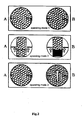
- a dividing piston 13 and a measuring press 9 serve to bring a free space formed by a gap between a bottom light reflector 11 and said dividing piston 13 into coincidence with the axis of a viewing port 2, to enable a direct passage of a luminous flux from a light source 3 through a light oil to the opposite viewing port.
- a reservoir pressure is set using the measuring press 9.
- Ps saturation pressure
- the use of the present invention makes possible a significant expansion of the fields of applying the claimed equilibrium bomb through the provision of means for the study of a phase behavior of dark and light "volatile" stratified oils and also gas-condensate systems having a broad range of potential contents of C 5+ liquid hydrocarbons, and an increase in precision measurements of micro volumes of a liquid phase precipitated there from when depressurizing.
Landscapes
- Chemical & Material Sciences (AREA)
- Health & Medical Sciences (AREA)
- Life Sciences & Earth Sciences (AREA)
- Immunology (AREA)
- Engineering & Computer Science (AREA)
- Biochemistry (AREA)
- General Health & Medical Sciences (AREA)
- General Physics & Mathematics (AREA)
- Physics & Mathematics (AREA)
- Pathology (AREA)
- Analytical Chemistry (AREA)
- Chemical Kinetics & Catalysis (AREA)
- General Chemical & Material Sciences (AREA)
- Oil, Petroleum & Natural Gas (AREA)
- Food Science & Technology (AREA)
- Medicinal Chemistry (AREA)
- Investigating Or Analysing Materials By Optical Means (AREA)
- Exposure And Positioning Against Photoresist Photosensitive Materials (AREA)
- Investigating Or Analyzing Materials Using Thermal Means (AREA)
Claims (2)
- Ein Gleichgesichtskolben zur Untersuchung eines Phasenverhaltens von Kohlenwasserstoffen aufweisend- einen Temperatur-kontrollierten zylindrischen Hochdruck-Behälter (1), der eine Anlagefläche und Seitenöffnungen (5-8) mit Anschlussstutzen aufweist,- zwei Beobachtungsfenster (2),- eine Lichtquelle (3),- obere und untere Reflektoren (10, 11), die fest aneinander gekoppelt und innerhalb des Behälters (1) angeordnet sind,wobei- der Kolben mit einem Trennkolben (13) versehen ist, der mit einem festen Spalt am unteren Reflektor (11) befestigt ist,- der untere Reflektor (11) in Form eines Zylinders ausgebildet ist, dessen einer Boden zwei flache Spiegelflächen aufweist, die symmetrisch in einem Winkel von 45° in Bezug auf die Zylinderachse geneigt sind,- der Kolben außerdem mit einem Bypass-Kanal (15) versehen ist, der durch ein Stopp-Ventil (14) Räume über und unterhalb des Kolbens (13) miteinander verbindet,- die Reflektoren (10, 11) mit einem Spalt relativ zu einer Behälter-Innenwand angeordnet und miteinander mittels einer rechteckigen Trennwand (12) verbunden sind, die entlang der Achse des Behälters (1) positioniert ist und eine Öffnung auf einer Höhe des oberen Reflektors (10) aufweist,- der obere Reflektor (10) in Form eines Zylinders ausgebildet ist, dessen einer Boden von der Membran (12) aus gesehen eine innere Aussparung aufweist, die zwei symmetrische Spiegelflächen ausbildet, die in einem Winkel von 45° in Bezug auf die Zylinderachse geneigt sind,- die Beobachtungsfenster (2) an diametral gegenüberliegenden Stellen an der lateralen Wand des Behälters (1) auf einer Höhe der Lichtquelle (3) vorgesehen sind, und- die Spiegelflächen des oberen Reflektors (10) und des unteren Reflektors (11) so angeordnet sind, dass, wenn der untere Reflektor auf der Höhe der Beobachtungsfenster angeordnet ist, ein durch ein Beobachtungsfenster von der Lichtquelle (3) kommender Lichtfluss vom unteren Reflektor (11) zum oberen Reflektor (10) reflektiert wird, durch die Öffnung auf einer Höhe des oberen Reflektors (10) hindurchtritt, vom oberen Reflektor (10) zum unteren Reflektor (11) reflektiert wird, und vom unteren Reflektor (11) zum anderen Beobachtungsfenster (2) reflektiert wird.
- Ein Kolben wie in Anspruch 1 definiert, dadurch gekennzeichnet, dass der andere Boden des unteren Reflektors (11) mit einem radialen Schlitz versehen ist, und der radiale Schlitz des unteren Reflektors (11) rechtwinklig zur Trennwand (12) angeordnet ist, die mit Hilfe von zwei Nuten an der Innenfläche des Behälters (1) in einer rechtwinkligen Richtung zur Achse der Beobachtungsfenster (2) fixiert ist.
Applications Claiming Priority (2)
| Application Number | Priority Date | Filing Date | Title |
|---|---|---|---|
| RU2002131993/28A RU2235313C1 (ru) | 2002-11-27 | 2002-11-27 | Бомба равновесия для изучения фазового поведения углеводородов |
| PCT/RU2003/000403 WO2004048952A1 (en) | 2002-11-27 | 2003-09-15 | Equilibrium bomb for studying phase behaviour of hydrocarbons |
Publications (3)
| Publication Number | Publication Date |
|---|---|
| EP1677100A1 EP1677100A1 (de) | 2006-07-05 |
| EP1677100A4 EP1677100A4 (de) | 2008-04-30 |
| EP1677100B1 true EP1677100B1 (de) | 2010-03-31 |
Family
ID=32390767
Family Applications (1)
| Application Number | Title | Priority Date | Filing Date |
|---|---|---|---|
| EP03751659A Expired - Lifetime EP1677100B1 (de) | 2002-11-27 | 2003-09-15 | Gleichgewichtskolben zur untersuchung des phasenverhaltens von kohlenwasserstoffen |
Country Status (4)
| Country | Link |
|---|---|
| EP (1) | EP1677100B1 (de) |
| DE (1) | DE60331968D1 (de) |
| RU (1) | RU2235313C1 (de) |
| WO (1) | WO2004048952A1 (de) |
Cited By (3)
| Publication number | Priority date | Publication date | Assignee | Title |
|---|---|---|---|---|
| US8380446B2 (en) | 2010-06-14 | 2013-02-19 | Schlumberger Technology Corporation | System and method for determining the phase envelope of a gas condensate |
| US10895544B2 (en) | 2014-08-21 | 2021-01-19 | Schlumberger Technology Corporation | Measurement of liquid parameters using a microfluidic device |
| US12078521B2 (en) | 2019-05-22 | 2024-09-03 | Totalenergies Onetech | Device for determining a volume of liquid in a fluid sample |
Families Citing this family (5)
| Publication number | Priority date | Publication date | Assignee | Title |
|---|---|---|---|---|
| RU2434220C1 (ru) * | 2010-09-17 | 2011-11-20 | Федеральное казенное предприятие "Государственный научно-исследовательский институт химических продуктов" (ФКП "ГосНИИХП") | Устройство для определения термической стойкости веществ |
| RU175813U1 (ru) * | 2017-03-28 | 2017-12-20 | Общество с ограниченной ответственностью "Газпром проектирование" | Устройство для определения давления насыщения по нефти и определения давления начала кипения конденсата |
| WO2019022630A1 (ru) * | 2017-07-25 | 2019-01-31 | Федеральное казенное предприятие "Государственный научно-исследовательский институт химических продуктов" (ФКП "ГосНИИХП") | Устройство для определения термической стойкости веществ |
| CN110261425A (zh) * | 2019-07-23 | 2019-09-20 | 海安华达石油仪器有限公司 | 一种可视化高压物性凝析分析装置 |
| GB2586649B (en) * | 2019-09-02 | 2022-09-28 | Schlumberger Technology Bv | Pressure cell systems for use with drilling fluid |
Family Cites Families (5)
| Publication number | Priority date | Publication date | Assignee | Title |
|---|---|---|---|---|
| US2662393A (en) * | 1950-12-29 | 1953-12-15 | Stanolind Oil & Gas Co | High-pressure windowed cell |
| US4804274A (en) * | 1986-12-30 | 1989-02-14 | Mobil Oil Corporation | Method and apparatus for determining phase transition temperature using laser attenuation |
| SU1679337A1 (ru) * | 1989-03-06 | 1991-09-23 | Предприятие П/Я А-7731 | Гигрометр |
| SU1808127A3 (en) * | 1991-01-16 | 1993-04-07 | Aleksandr V Urusov | Device for investigating pvt-relation of gas-liquid mixture |
| US5758968A (en) * | 1996-07-15 | 1998-06-02 | Digimelt Inc. | Optically based method and apparatus for detecting a phase transition temperature of a material of interest |
-
2002
- 2002-11-27 RU RU2002131993/28A patent/RU2235313C1/ru not_active IP Right Cessation
-
2003
- 2003-09-15 WO PCT/RU2003/000403 patent/WO2004048952A1/ru not_active Ceased
- 2003-09-15 DE DE60331968T patent/DE60331968D1/de not_active Expired - Lifetime
- 2003-09-15 EP EP03751659A patent/EP1677100B1/de not_active Expired - Lifetime
Non-Patent Citations (1)
| Title |
|---|
| VELIKOVSKY ET AL.: "STUDIES OF GAS CONDENSATE DEPOSITS", VNINGAZ, vol. 17/25, Moscow, 1962, pages 265 - 269 * |
Cited By (3)
| Publication number | Priority date | Publication date | Assignee | Title |
|---|---|---|---|---|
| US8380446B2 (en) | 2010-06-14 | 2013-02-19 | Schlumberger Technology Corporation | System and method for determining the phase envelope of a gas condensate |
| US10895544B2 (en) | 2014-08-21 | 2021-01-19 | Schlumberger Technology Corporation | Measurement of liquid parameters using a microfluidic device |
| US12078521B2 (en) | 2019-05-22 | 2024-09-03 | Totalenergies Onetech | Device for determining a volume of liquid in a fluid sample |
Also Published As
| Publication number | Publication date |
|---|---|
| EP1677100A4 (de) | 2008-04-30 |
| WO2004048952A1 (en) | 2004-06-10 |
| RU2235313C1 (ru) | 2004-08-27 |
| DE60331968D1 (de) | 2010-05-12 |
| EP1677100A1 (de) | 2006-07-05 |
Similar Documents
| Publication | Publication Date | Title |
|---|---|---|
| US4425810A (en) | Apparatus for physical properties measurements at high temperatures and pressures | |
| Moussallam et al. | CO2 solubility in kimberlite melts | |
| EP1677100A1 (de) | Gleichgewichtskolben zur untersuchung des phasenverhaltens von kohlenwasserstoffen | |
| US5747674A (en) | Device for performing thermodynamic measurements on multiphase fluids at very high pressures and temperatures | |
| SA109300588B1 (ar) | تحليل قياسات الضغط والحجم ودرجة الحرارة للموائع المضغوطة | |
| Lhoták et al. | Vapour-liquid equilibria in the ethane-n-butane system at high pressures | |
| WO2002054076A3 (de) | Sensor zur lumineszenz-optischen bestimmung eines analyten | |
| CN116840192B (zh) | 一种跨尺度凝析气雾状流重力沉降弛豫时间测试方法 | |
| CN115950577A (zh) | 一种基于微流控技术的最小混相压力测量系统及其测量方法 | |
| US6975392B2 (en) | Enhanced sensitivity differential refractometer measurement cell | |
| Derjaguin | Correct form of the equation of capillary condensation in porous bodies in application to the separation of adsorption and capillary condensation in slits and porous bodies of known structure and determination of their structure by adsorption and sorption isotherms | |
| JP2005156553A (ja) | 屈折計セル、その第2のチャンバの角度を判定する方法、液体の屈折率および屈折率差を測定するための方法 | |
| US20220221440A1 (en) | High temperature high pressure (hthp) cell in sum frequency generation (sfg) spectroscopy for oil/brine interface analysis with reservoir conditions and dynamic compositions | |
| NO303415B1 (no) | Anordning for utf°relse av termodynamiske mÕlinger pÕ pr°ver av stoffer som sµrlig stammer fra petroleumholdige omrÕder | |
| US1917846A (en) | Gas pressure apparatus | |
| RU175813U1 (ru) | Устройство для определения давления насыщения по нефти и определения давления начала кипения конденсата | |
| RU111294U1 (ru) | Бомба равновесия для изучения фазового поведения углеводородов | |
| Pehl et al. | An in situ technique to visualize temperature and velocity fields in liquid biotechnical substances at high pressure | |
| CN101171503B (zh) | 示差折射率的测量装置 | |
| US20210247661A1 (en) | High temperature high pressure (hthp) cell in sum frequency generation (sfg) spectroscopy for liquid/liquid interface analysis | |
| Engström et al. | Effects of pressure on red blood cell geometry during micropipette aspiration | |
| Baierlein et al. | [33] Pressure-induced dissociation of ribosomes | |
| Caldin et al. | A stopped-flow apparatus with temperature control, fibre optics, and chemically inert flow system | |
| Tekmen et al. | High-pressure cell for fluorescence fluctuation spectroscopy | |
| Strand et al. | Interface light-scattering on a methane–decane system in the near-critical region at 37.8 C (100 F) |
Legal Events
| Date | Code | Title | Description |
|---|---|---|---|
| PUAI | Public reference made under article 153(3) epc to a published international application that has entered the european phase |
Free format text: ORIGINAL CODE: 0009012 |
|
| 17P | Request for examination filed |
Effective date: 20050830 |
|
| AK | Designated contracting states |
Kind code of ref document: A1 Designated state(s): DE FR GB |
|
| A4 | Supplementary search report drawn up and despatched |
Effective date: 20080401 |
|
| RAP1 | Party data changed (applicant data changed or rights of an application transferred) |
Owner name: GAZPROM DOBYCHA ORENBURG |
|
| 17Q | First examination report despatched |
Effective date: 20090226 |
|
| GRAP | Despatch of communication of intention to grant a patent |
Free format text: ORIGINAL CODE: EPIDOSNIGR1 |
|
| RBV | Designated contracting states (corrected) |
Designated state(s): DE FR GB |
|
| GRAS | Grant fee paid |
Free format text: ORIGINAL CODE: EPIDOSNIGR3 |
|
| GRAA | (expected) grant |
Free format text: ORIGINAL CODE: 0009210 |
|
| AK | Designated contracting states |
Kind code of ref document: B1 Designated state(s): DE FR GB |
|
| REG | Reference to a national code |
Ref country code: GB Ref legal event code: FG4D |
|
| REF | Corresponds to: |
Ref document number: 60331968 Country of ref document: DE Date of ref document: 20100512 Kind code of ref document: P |
|
| PGFP | Annual fee paid to national office [announced via postgrant information from national office to epo] |
Ref country code: GB Payment date: 20100928 Year of fee payment: 8 |
|
| PGFP | Annual fee paid to national office [announced via postgrant information from national office to epo] |
Ref country code: FR Payment date: 20101109 Year of fee payment: 8 |
|
| PLBE | No opposition filed within time limit |
Free format text: ORIGINAL CODE: 0009261 |
|
| STAA | Information on the status of an ep patent application or granted ep patent |
Free format text: STATUS: NO OPPOSITION FILED WITHIN TIME LIMIT |
|
| PGFP | Annual fee paid to national office [announced via postgrant information from national office to epo] |
Ref country code: DE Payment date: 20100929 Year of fee payment: 8 |
|
| 26N | No opposition filed |
Effective date: 20110104 |
|
| GBPC | Gb: european patent ceased through non-payment of renewal fee |
Effective date: 20110915 |
|
| REG | Reference to a national code |
Ref country code: FR Ref legal event code: ST Effective date: 20120531 |
|
| REG | Reference to a national code |
Ref country code: DE Ref legal event code: R119 Ref document number: 60331968 Country of ref document: DE Effective date: 20120403 |
|
| PG25 | Lapsed in a contracting state [announced via postgrant information from national office to epo] |
Ref country code: DE Free format text: LAPSE BECAUSE OF NON-PAYMENT OF DUE FEES Effective date: 20120403 |
|
| PG25 | Lapsed in a contracting state [announced via postgrant information from national office to epo] |
Ref country code: GB Free format text: LAPSE BECAUSE OF NON-PAYMENT OF DUE FEES Effective date: 20110915 Ref country code: FR Free format text: LAPSE BECAUSE OF NON-PAYMENT OF DUE FEES Effective date: 20110930 |