EP1677063A1 - KILN a method of manufacturing porous ceramic baked body using the KILN - Google Patents
KILN a method of manufacturing porous ceramic baked body using the KILN Download PDFInfo
- Publication number
- EP1677063A1 EP1677063A1 EP05768924A EP05768924A EP1677063A1 EP 1677063 A1 EP1677063 A1 EP 1677063A1 EP 05768924 A EP05768924 A EP 05768924A EP 05768924 A EP05768924 A EP 05768924A EP 1677063 A1 EP1677063 A1 EP 1677063A1
- Authority
- EP
- European Patent Office
- Prior art keywords
- firing
- housing
- insulative
- heat
- restriction structure
- Prior art date
- Legal status (The legal status is an assumption and is not a legal conclusion. Google has not performed a legal analysis and makes no representation as to the accuracy of the status listed.)
- Withdrawn
Links
- 239000000919 ceramic Substances 0.000 title claims description 94
- 238000004519 manufacturing process Methods 0.000 title claims description 28
- 238000010304 firing Methods 0.000 claims abstract description 164
- 238000003780 insertion Methods 0.000 claims abstract description 15
- 230000037431 insertion Effects 0.000 claims abstract description 15
- 230000020169 heat generation Effects 0.000 claims abstract description 10
- 238000007789 sealing Methods 0.000 claims abstract description 8
- 238000000034 method Methods 0.000 claims description 22
- 239000000203 mixture Substances 0.000 claims description 12
- 239000000843 powder Substances 0.000 claims description 6
- 239000007789 gas Substances 0.000 description 54
- 239000010410 layer Substances 0.000 description 30
- 239000000463 material Substances 0.000 description 26
- 230000006866 deterioration Effects 0.000 description 24
- HBMJWWWQQXIZIP-UHFFFAOYSA-N silicon carbide Chemical compound [Si+]#[C-] HBMJWWWQQXIZIP-UHFFFAOYSA-N 0.000 description 21
- 229910010271 silicon carbide Inorganic materials 0.000 description 14
- 239000002245 particle Substances 0.000 description 13
- OKTJSMMVPCPJKN-UHFFFAOYSA-N Carbon Chemical compound [C] OKTJSMMVPCPJKN-UHFFFAOYSA-N 0.000 description 9
- 239000002585 base Substances 0.000 description 9
- 239000003054 catalyst Substances 0.000 description 9
- 238000010438 heat treatment Methods 0.000 description 9
- 230000004927 fusion Effects 0.000 description 8
- 239000011230 binding agent Substances 0.000 description 7
- 239000011247 coating layer Substances 0.000 description 7
- XUIMIQQOPSSXEZ-UHFFFAOYSA-N Silicon Chemical compound [Si] XUIMIQQOPSSXEZ-UHFFFAOYSA-N 0.000 description 6
- 229910052799 carbon Inorganic materials 0.000 description 6
- 229910052751 metal Inorganic materials 0.000 description 6
- 229910052710 silicon Inorganic materials 0.000 description 6
- 239000010703 silicon Substances 0.000 description 6
- 238000001816 cooling Methods 0.000 description 5
- 239000002184 metal Substances 0.000 description 5
- 239000013618 particulate matter Substances 0.000 description 5
- 238000005192 partition Methods 0.000 description 5
- 229910021426 porous silicon Inorganic materials 0.000 description 5
- XKRFYHLGVUSROY-UHFFFAOYSA-N Argon Chemical compound [Ar] XKRFYHLGVUSROY-UHFFFAOYSA-N 0.000 description 4
- VYPSYNLAJGMNEJ-UHFFFAOYSA-N Silicium dioxide Chemical compound O=[Si]=O VYPSYNLAJGMNEJ-UHFFFAOYSA-N 0.000 description 4
- 239000000853 adhesive Substances 0.000 description 4
- 230000001070 adhesive effect Effects 0.000 description 4
- 230000000052 comparative effect Effects 0.000 description 4
- 239000000835 fiber Substances 0.000 description 4
- 238000011068 loading method Methods 0.000 description 4
- 239000011148 porous material Substances 0.000 description 4
- 238000005245 sintering Methods 0.000 description 4
- XLYOFNOQVPJJNP-UHFFFAOYSA-N water Substances O XLYOFNOQVPJJNP-UHFFFAOYSA-N 0.000 description 4
- UHOVQNZJYSORNB-UHFFFAOYSA-N Benzene Chemical compound C1=CC=CC=C1 UHOVQNZJYSORNB-UHFFFAOYSA-N 0.000 description 3
- 229920002134 Carboxymethyl cellulose Polymers 0.000 description 3
- OKKJLVBELUTLKV-UHFFFAOYSA-N Methanol Chemical compound OC OKKJLVBELUTLKV-UHFFFAOYSA-N 0.000 description 3
- 229910052581 Si3N4 Inorganic materials 0.000 description 3
- PNEYBMLMFCGWSK-UHFFFAOYSA-N aluminium oxide Inorganic materials [O-2].[O-2].[O-2].[Al+3].[Al+3] PNEYBMLMFCGWSK-UHFFFAOYSA-N 0.000 description 3
- 239000001768 carboxy methyl cellulose Substances 0.000 description 3
- 235000010948 carboxy methyl cellulose Nutrition 0.000 description 3
- 239000008112 carboxymethyl-cellulose Substances 0.000 description 3
- 229910010293 ceramic material Inorganic materials 0.000 description 3
- 239000011248 coating agent Substances 0.000 description 3
- 238000000576 coating method Methods 0.000 description 3
- 229910002804 graphite Inorganic materials 0.000 description 3
- 239000010439 graphite Substances 0.000 description 3
- 238000002156 mixing Methods 0.000 description 3
- 229910052574 oxide ceramic Inorganic materials 0.000 description 3
- 239000011224 oxide ceramic Substances 0.000 description 3
- 230000002035 prolonged effect Effects 0.000 description 3
- HQVNEWCFYHHQES-UHFFFAOYSA-N silicon nitride Chemical compound N12[Si]34N5[Si]62N3[Si]51N64 HQVNEWCFYHHQES-UHFFFAOYSA-N 0.000 description 3
- 239000002904 solvent Substances 0.000 description 3
- 229910000505 Al2TiO5 Inorganic materials 0.000 description 2
- PZNSFCLAULLKQX-UHFFFAOYSA-N Boron nitride Chemical compound N#B PZNSFCLAULLKQX-UHFFFAOYSA-N 0.000 description 2
- KDLHZDBZIXYQEI-UHFFFAOYSA-N Palladium Chemical compound [Pd] KDLHZDBZIXYQEI-UHFFFAOYSA-N 0.000 description 2
- MCMNRKCIXSYSNV-UHFFFAOYSA-N Zirconium dioxide Chemical compound O=[Zr]=O MCMNRKCIXSYSNV-UHFFFAOYSA-N 0.000 description 2
- 229910052783 alkali metal Inorganic materials 0.000 description 2
- 150000001340 alkali metals Chemical class 0.000 description 2
- 229910052784 alkaline earth metal Inorganic materials 0.000 description 2
- 229910052786 argon Inorganic materials 0.000 description 2
- 230000008901 benefit Effects 0.000 description 2
- 238000002485 combustion reaction Methods 0.000 description 2
- 229910052878 cordierite Inorganic materials 0.000 description 2
- 238000005238 degreasing Methods 0.000 description 2
- JSKIRARMQDRGJZ-UHFFFAOYSA-N dimagnesium dioxido-bis[(1-oxido-3-oxo-2,4,6,8,9-pentaoxa-1,3-disila-5,7-dialuminabicyclo[3.3.1]nonan-7-yl)oxy]silane Chemical compound [Mg++].[Mg++].[O-][Si]([O-])(O[Al]1O[Al]2O[Si](=O)O[Si]([O-])(O1)O2)O[Al]1O[Al]2O[Si](=O)O[Si]([O-])(O1)O2 JSKIRARMQDRGJZ-UHFFFAOYSA-N 0.000 description 2
- 238000001035 drying Methods 0.000 description 2
- 230000000694 effects Effects 0.000 description 2
- 239000010954 inorganic particle Substances 0.000 description 2
- 229920000609 methyl cellulose Polymers 0.000 description 2
- 239000001923 methylcellulose Substances 0.000 description 2
- 235000010981 methylcellulose Nutrition 0.000 description 2
- 150000004767 nitrides Chemical class 0.000 description 2
- 229910000510 noble metal Inorganic materials 0.000 description 2
- 239000003960 organic solvent Substances 0.000 description 2
- BASFCYQUMIYNBI-UHFFFAOYSA-N platinum Chemical compound [Pt] BASFCYQUMIYNBI-UHFFFAOYSA-N 0.000 description 2
- AABBHSMFGKYLKE-SNAWJCMRSA-N propan-2-yl (e)-but-2-enoate Chemical compound C\C=C\C(=O)OC(C)C AABBHSMFGKYLKE-SNAWJCMRSA-N 0.000 description 2
- 230000005855 radiation Effects 0.000 description 2
- -1 sialon Chemical compound 0.000 description 2
- 239000000377 silicon dioxide Substances 0.000 description 2
- KXGFMDJXCMQABM-UHFFFAOYSA-N 2-methoxy-6-methylphenol Chemical compound [CH]OC1=CC=CC([CH])=C1O KXGFMDJXCMQABM-UHFFFAOYSA-N 0.000 description 1
- IJGRMHOSHXDMSA-UHFFFAOYSA-N Atomic nitrogen Chemical compound N#N IJGRMHOSHXDMSA-UHFFFAOYSA-N 0.000 description 1
- 229910052582 BN Inorganic materials 0.000 description 1
- 229920000049 Carbon (fiber) Polymers 0.000 description 1
- 229920000663 Hydroxyethyl cellulose Polymers 0.000 description 1
- 239000004354 Hydroxyethyl cellulose Substances 0.000 description 1
- DGAQECJNVWCQMB-PUAWFVPOSA-M Ilexoside XXIX Chemical compound C[C@@H]1CC[C@@]2(CC[C@@]3(C(=CC[C@H]4[C@]3(CC[C@@H]5[C@@]4(CC[C@@H](C5(C)C)OS(=O)(=O)[O-])C)C)[C@@H]2[C@]1(C)O)C)C(=O)O[C@H]6[C@@H]([C@H]([C@@H]([C@H](O6)CO)O)O)O.[Na+] DGAQECJNVWCQMB-PUAWFVPOSA-M 0.000 description 1
- BPQQTUXANYXVAA-UHFFFAOYSA-N Orthosilicate Chemical compound [O-][Si]([O-])([O-])[O-] BPQQTUXANYXVAA-UHFFFAOYSA-N 0.000 description 1
- 239000002202 Polyethylene glycol Substances 0.000 description 1
- ZLMJMSJWJFRBEC-UHFFFAOYSA-N Potassium Chemical compound [K] ZLMJMSJWJFRBEC-UHFFFAOYSA-N 0.000 description 1
- NRTOMJZYCJJWKI-UHFFFAOYSA-N Titanium nitride Chemical compound [Ti]#N NRTOMJZYCJJWKI-UHFFFAOYSA-N 0.000 description 1
- 229910026551 ZrC Inorganic materials 0.000 description 1
- OTCHGXYCWNXDOA-UHFFFAOYSA-N [C].[Zr] Chemical compound [C].[Zr] OTCHGXYCWNXDOA-UHFFFAOYSA-N 0.000 description 1
- JDXFWPNOKMPSEM-UHFFFAOYSA-N [Si].ClOCl Chemical compound [Si].ClOCl JDXFWPNOKMPSEM-UHFFFAOYSA-N 0.000 description 1
- 239000006096 absorbing agent Substances 0.000 description 1
- QVGXLLKOCUKJST-UHFFFAOYSA-N atomic oxygen Chemical compound [O] QVGXLLKOCUKJST-UHFFFAOYSA-N 0.000 description 1
- 229910052788 barium Inorganic materials 0.000 description 1
- DSAJWYNOEDNPEQ-UHFFFAOYSA-N barium atom Chemical compound [Ba] DSAJWYNOEDNPEQ-UHFFFAOYSA-N 0.000 description 1
- 230000005540 biological transmission Effects 0.000 description 1
- 239000004917 carbon fiber Substances 0.000 description 1
- CETPSERCERDGAM-UHFFFAOYSA-N ceric oxide Chemical compound O=[Ce]=O CETPSERCERDGAM-UHFFFAOYSA-N 0.000 description 1
- 229910000422 cerium(IV) oxide Inorganic materials 0.000 description 1
- 229910052681 coesite Inorganic materials 0.000 description 1
- 239000002131 composite material Substances 0.000 description 1
- 238000000748 compression moulding Methods 0.000 description 1
- 239000000498 cooling water Substances 0.000 description 1
- PMHQVHHXPFUNSP-UHFFFAOYSA-M copper(1+);methylsulfanylmethane;bromide Chemical compound Br[Cu].CSC PMHQVHHXPFUNSP-UHFFFAOYSA-M 0.000 description 1
- 229910052906 cristobalite Inorganic materials 0.000 description 1
- 230000003247 decreasing effect Effects 0.000 description 1
- 229910003460 diamond Inorganic materials 0.000 description 1
- 239000010432 diamond Substances 0.000 description 1
- 229910001873 dinitrogen Inorganic materials 0.000 description 1
- KZHJGOXRZJKJNY-UHFFFAOYSA-N dioxosilane;oxo(oxoalumanyloxy)alumane Chemical compound O=[Si]=O.O=[Si]=O.O=[Al]O[Al]=O.O=[Al]O[Al]=O.O=[Al]O[Al]=O KZHJGOXRZJKJNY-UHFFFAOYSA-N 0.000 description 1
- 239000003822 epoxy resin Substances 0.000 description 1
- 238000011156 evaluation Methods 0.000 description 1
- 238000001125 extrusion Methods 0.000 description 1
- 239000003779 heat-resistant material Substances 0.000 description 1
- 235000019447 hydroxyethyl cellulose Nutrition 0.000 description 1
- 238000005470 impregnation Methods 0.000 description 1
- 239000012784 inorganic fiber Substances 0.000 description 1
- 238000009413 insulation Methods 0.000 description 1
- 238000004898 kneading Methods 0.000 description 1
- 239000000314 lubricant Substances 0.000 description 1
- 229910000473 manganese(VI) oxide Inorganic materials 0.000 description 1
- 239000007769 metal material Substances 0.000 description 1
- NFFIWVVINABMKP-UHFFFAOYSA-N methylidynetantalum Chemical compound [Ta]#C NFFIWVVINABMKP-UHFFFAOYSA-N 0.000 description 1
- 238000012986 modification Methods 0.000 description 1
- 230000004048 modification Effects 0.000 description 1
- 238000000465 moulding Methods 0.000 description 1
- 229910052863 mullite Inorganic materials 0.000 description 1
- 229910001120 nichrome Inorganic materials 0.000 description 1
- 229910052575 non-oxide ceramic Inorganic materials 0.000 description 1
- 239000011225 non-oxide ceramic Substances 0.000 description 1
- 239000001301 oxygen Substances 0.000 description 1
- 229910052760 oxygen Inorganic materials 0.000 description 1
- 229910052763 palladium Inorganic materials 0.000 description 1
- 239000005011 phenolic resin Substances 0.000 description 1
- 229920001568 phenolic resin Polymers 0.000 description 1
- 239000004014 plasticizer Substances 0.000 description 1
- 229910052697 platinum Inorganic materials 0.000 description 1
- 229920000647 polyepoxide Polymers 0.000 description 1
- 229920001223 polyethylene glycol Polymers 0.000 description 1
- 229910052700 potassium Inorganic materials 0.000 description 1
- 239000011591 potassium Substances 0.000 description 1
- 239000002994 raw material Substances 0.000 description 1
- 229910052703 rhodium Inorganic materials 0.000 description 1
- 239000010948 rhodium Substances 0.000 description 1
- MHOVAHRLVXNVSD-UHFFFAOYSA-N rhodium atom Chemical compound [Rh] MHOVAHRLVXNVSD-UHFFFAOYSA-N 0.000 description 1
- 238000005096 rolling process Methods 0.000 description 1
- 239000004065 semiconductor Substances 0.000 description 1
- RMAQACBXLXPBSY-UHFFFAOYSA-N silicic acid Chemical compound O[Si](O)(O)O RMAQACBXLXPBSY-UHFFFAOYSA-N 0.000 description 1
- 229910052708 sodium Inorganic materials 0.000 description 1
- 239000011734 sodium Substances 0.000 description 1
- 229910052682 stishovite Inorganic materials 0.000 description 1
- 229910003468 tantalcarbide Inorganic materials 0.000 description 1
- 238000012360 testing method Methods 0.000 description 1
- 229910052905 tridymite Inorganic materials 0.000 description 1
- MTPVUVINMAGMJL-UHFFFAOYSA-N trimethyl(1,1,2,2,2-pentafluoroethyl)silane Chemical compound C[Si](C)(C)C(F)(F)C(F)(F)F MTPVUVINMAGMJL-UHFFFAOYSA-N 0.000 description 1
- UONOETXJSWQNOL-UHFFFAOYSA-N tungsten carbide Chemical compound [W+]#[C-] UONOETXJSWQNOL-UHFFFAOYSA-N 0.000 description 1
Images



Classifications
-
- F—MECHANICAL ENGINEERING; LIGHTING; HEATING; WEAPONS; BLASTING
- F27—FURNACES; KILNS; OVENS; RETORTS
- F27D—DETAILS OR ACCESSORIES OF FURNACES, KILNS, OVENS OR RETORTS, IN SO FAR AS THEY ARE OF KINDS OCCURRING IN MORE THAN ONE KIND OF FURNACE
- F27D11/00—Arrangement of elements for electric heating in or on furnaces
- F27D11/02—Ohmic resistance heating
-
- F—MECHANICAL ENGINEERING; LIGHTING; HEATING; WEAPONS; BLASTING
- F27—FURNACES; KILNS; OVENS; RETORTS
- F27B—FURNACES, KILNS, OVENS OR RETORTS IN GENERAL; OPEN SINTERING OR LIKE APPARATUS
- F27B9/00—Furnaces through which the charge is moved mechanically, e.g. of tunnel type; Similar furnaces in which the charge moves by gravity
- F27B9/30—Details, accessories or equipment specially adapted for furnaces of these types
- F27B9/36—Arrangements of heating devices
-
- F—MECHANICAL ENGINEERING; LIGHTING; HEATING; WEAPONS; BLASTING
- F27—FURNACES; KILNS; OVENS; RETORTS
- F27D—DETAILS OR ACCESSORIES OF FURNACES, KILNS, OVENS OR RETORTS, IN SO FAR AS THEY ARE OF KINDS OCCURRING IN MORE THAN ONE KIND OF FURNACE
- F27D99/00—Subject matter not provided for in other groups of this subclass
- F27D99/0001—Heating elements or systems
- F27D99/0006—Electric heating elements or system
-
- H—ELECTRICITY
- H05—ELECTRIC TECHNIQUES NOT OTHERWISE PROVIDED FOR
- H05B—ELECTRIC HEATING; ELECTRIC LIGHT SOURCES NOT OTHERWISE PROVIDED FOR; CIRCUIT ARRANGEMENTS FOR ELECTRIC LIGHT SOURCES, IN GENERAL
- H05B3/00—Ohmic-resistance heating
- H05B3/62—Heating elements specially adapted for furnaces
-
- H—ELECTRICITY
- H05—ELECTRIC TECHNIQUES NOT OTHERWISE PROVIDED FOR
- H05B—ELECTRIC HEATING; ELECTRIC LIGHT SOURCES NOT OTHERWISE PROVIDED FOR; CIRCUIT ARRANGEMENTS FOR ELECTRIC LIGHT SOURCES, IN GENERAL
- H05B3/00—Ohmic-resistance heating
- H05B3/62—Heating elements specially adapted for furnaces
- H05B3/66—Supports or mountings for heaters on or in the wall or roof
Definitions
- the present invention relates to a firing furnace, and more particularly, to a resistance-heating firing furnace for firing a molded product of a ceramic material and a method for manufacturing a porous ceramic fired object using such a firing furnace.
- a molded product of a ceramic material is typically fired in a resistance-heating firing furnace at a relatively high temperature.
- a resistance-heating firing furnace is disclosed in Patent Publication 1.
- This firing furnace includes a plurality of rod heaters arranged in a firing chamber (muffle) for firing a molded product.
- a material having superior heat-resistance is used for the resistance-heating firing furnace to enable firing at high temperatures.
- electric current is supplied to the rod heaters to generate heat. The radiation heat from the rod heaters heats and sinters the molded product in the firing chamber to manufacture a ceramic sinter.
- a conventional resistance-heating firing furnace includes a power feeding unit for feeding power to a heater.
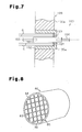
- a power feeding unit 100 includes a connector 101 for connecting an electrode member 104, which is connected to an external power supply, to a heater 105, a fixing member 102 for covering the connector 101, and an insulative member 103 for electrically insulating the connector 101 and the fixing member 102.
- the firing furnace has a housing with an inner wall along which a heat insulative layer 106 is applied. In part of the heat insulative layer 106, a through hole 106a is formed to receive the power feeding unit 100.
- the fixing member 102 of the power feeding unit 100 is fitted to the through hole 106a.
- An insertion hole 107 is formed in the fixing member 102 for insertion of the connector 101.
- the insulative member 103 which is annular, is held between the wall of the insertion hole 107 and the connector 101 to electrically insulate the wall of the insertion hole and the connector 101.
- Patent Publication 1 Japanese Patent Laid-Open Publication No. 2002-193670
- the radiation heat of the heaters 105 heats the gas generated from firing subjects in the firing furnace.
- hot gas G comes into contact with the insulative member 103 and enhances deterioration and fusion of the insulative member 103.
- the insulative member 103 must be frequently exchanged. This lowers the operation efficiency of the firing furnace.
- one aspect of the present invention provides a firing furnace, connected to an external power supply, for firing a firing subject.
- the firing furnace is provided with a housing including a firing chamber for accommodating the firing subject.
- a plurality of heat generation bodies are arranged in the housing and generate heat with power supplied from the external power supply to heat the firing subject in the firing chamber.
- a connection member connects the external power supply and each heat generation body.
- a fixing member is attached to the housing and includes an insertion hole for receiving the connection member.
- An insulative member seals a space between the insertion hole and the connection member.
- a restriction structure restricts a flow of gas produced in the housing and directed through a gap between the fixing member and the connection member toward the insulative member.
- the method includes forming a firing subject from a composition containing ceramic powder, and firing the firing subject with a firing furnace that includes a housing having a firing chamber for accommodating the firing subject, a plurality of heat generation bodies arranged in the housing for generating heat with power supplied from an external power supply to heat the firing subject in the firing chamber, a connection member for connecting the external power supply and each heat generation body, a fixing member attached to the housing and including an insertion hole for receiving the connection member, an insulative member for sealing a space between the insertion hole and the connection member, and a restriction structure for restricting a flow of gas produced in the housing directed through a gap between the fixing member and the connection member and toward the insulative member.
- the restriction structure is configured so as to restrict the flow of gas produced in the housing that enters the gap between the fixing member and the connection member.
- the restriction structure is arranged so that the insulative member is hidden behind the restriction structure when viewed from an inner side of the housing.
- the restriction structure includes at least one of a projection formed on an outer surface of the connection member and a projection formed on an inner surface of the fixing member.
- the restriction structure is a projection formed on the outer surface of the connection member and projects towards the inner surface of the fixing member.
- the restriction structure includes a projection extending along the outer surface of the connection member in the circumferential direction and a projection formed along the entire circumference of the inner surface of the fixing member.
- the restriction structure is configured to partially reduce the gap between the fixing member and the connection member.
- the housing includes a heat insulative layer, and the insulative member is arranged outward from the heat insulative layer. It is preferred that the housing includes a heat insulative layer, with part of the fixing member, the insulative member, and one end of the connection member being arranged outward from the heat insulative layer. It is preferred that the housing includes a heat insulative layer, the fixing member has an end arranged outward from the heat insulative layer, the end includes an inwardly extending lip for supporting the insulative member at a location outward from the heat insulative layer, and the restriction structure includes the inward lip.
- the insulative member is separated from the heat insulative layer by 10 to 100 mm.
- a continuous firing furnace for continuously firing a plurality of the firing subjects is provided.
- Fig. 1 shows a firing furnace 10 used in a manufacturing process of a ceramic product.
- the firing furnace 10 includes a housing 12 having a loading port 13a and an unloading port 15a. Firing subjects 11 are loaded into the housing 12 through the loading port 13a, and conveyed from the loading port 13a towards the unloading port 15a.
- the firing furnace 10 is a continuous firing furnace for continuously firing the firing subjects 11 in the housing 12.
- An example of a raw material for the firing subjects is ceramics such as porous silicon carbide (SiC), silicon nitride (SiN), sialon, cordierite, carbon, and the like.
- a pretreatment chamber 13, a firing chamber 14, and a cooling chamber 15 are defined in the housing 12.
- a plurality of conveying rollers 16 for conveying the firing subjects 11 are arranged along the bottom surfaces of the chambers 13 to 15.
- a support base 11b is mounted on the conveying rollers 16.
- the support base 11b supports a plurality of stacked firing jigs 11a. Firing subjects 11 are placed on each of the firing jigs 11a.
- the support base 11b is pushed from the loading port 13a towards the unloading port 15a.
- the firing subjects 11, the firing jigs 11a, and the support base 11b are conveyed, by the rolling of the conveying rollers 16, through the pretreatment chamber 13, the firing chamber 14, and the cooling chamber 15 sequentially in this order.
- An example of a firing subject 11 is a molded product formed by compression molding a ceramic material.
- the firing subject 11 is treated in the housing 12 as it moves at a predetermined speed.
- the firing subject 11 is fired when passing through the firing chamber 14.
- Ceramic powder, which forms each firing subject 11, is sintered during the conveying process to produce a sinter.
- the sinter is conveyed into the cooling chamber 15 and cooled down to a predetermined temperature.
- the cooled sinter is discharged from the unloading port 15a.
- Fig. 2 is a cross-sectional view taken along line 2-2 in Fig. 1.
- furnace walls 18 define an upper surface, a lower surface, and two side surfaces of the firing chamber 14.
- the furnace walls 18 and the firing jigs 11a are formed of a high heat resistant material such as carbon.
- a heat insulative layer 19 formed of carbon fibers or the like is arranged in the housing 12.
- a water-cooling jacket 20 is embedded in the housing 12 for circulating cooling water. The heat insulative layer 19 and the water-cooling jacket 20 prevent metal components of the housing 12 from being deteriorated or damaged by the heat of the firing chamber 14.
- a plurality of rod heaters (resistance heating elements) 23 are arranged on the upper side and lower side of the firing chamber 14, or arranged so as to sandwich the firing subjects 11, in the firing chamber 14.
- the rod heaters 23 are each cylindrical and has a longitudinal axis extending in the lateral direction of the housing 12 (in the direction orthogonal to the conveying direction of the firing subjects 11).
- the rod heaters 23 are held between opposite walls of the housing 12.
- the rod heaters 23 are arranged parallel to each other in predetermined intervals.
- the rod heaters 23 are arranged throughout the firing chamber 14 from the entering position to the exiting position of the firing subjects 11.
- An example of a material for forming the rod heater 23 is a ceramics material such as carbon having superior heat resistance.
- the preferred ceramics material is graphite that particularly has high heat resistance and that can easily be machined.
- Fig. 3 is an enlarged cross-sectional view taken at portion P in Fig. 2.
- the housing 12 has an inner surface along which a heat insulative layer 19 is applied.
- a plurality of fixing holes 31 for fixing the rod heaters 23 are formed in the heat insulative layer 19.
- a cylindrical fixing member 32 is fitted to each fixing hole 31.
- the fixing member 32 has an end 32a exposed from the outer surface 19a of the heat insulative layer 19.
- the fixing member 32 includes an insertion hole 34 for receiving a connector 35.
- the connector 35 connects a metal electrode member 37, which is directly or indirectly connected to an external power supply 40, and a rod heater 23, which is arranged inside the housing 12.
- the connector 35 has one end, or a first connecting portion 38a, located inside the housing 12, and another end, or a second connecting portion 38b, located outside the housing 12.
- the connector 35 also has a cylindrical enlarged diameter portion (restriction structure) 39 that is larger than other parts of the connector 35.
- Female threads are formed in the first and the second connecting portions 38a and 38b of the connector 35.
- Male threads screw are formed on the rod heater 23 and the electrode member 37 at portions connected to the first and the second connecting portions 38a and 38b of the connector 35, respectively.
- the rod heater 23 and the electrode member 37 are respectively mated with the first and the second connecting portions 38a and 38b of the connector 35 so as to electrical connect the rod heater 23 and the electrode member 37.
- the end 32a of the fixing member 32 includes an inwardly extending lip 32d.
- An annular insulative member 36 seals the gap between the lip 32d and the connector 35.
- the insulative member 36 and the end 32a of the fixing member 32. are arranged outward from the outer surface 19a of the heat insulative layer 19.
- the insulative member 36 is spaced from the heat insulative layer 19 by 10 to 100 mm, preferably, by 20 to 100 mm. If the spaced distance is less than 10 mm, the durability prolonging effect of the insulative member 36 may become insufficient since the hot gas G inside the housing 12 is likely to reach the insulative member 36. If the spaced distance exceeds 100 mm, it may become difficult to ensure space for installing the power feeding unit 30 due to the enlargement of the fixing member 32.
- An example of a material for forming the fixing member 32 and the connector 35 is a material having high heat-resistance such as carbon.
- the preferred material is graphite, which has superior heat-resistance and corrosion-resistance and is easily machined.
- An example of a material for forming the insulative member 36 is boron nitride (BN), which has a superior insulation property under high temperatures.
- the enlarged diameter portion (restriction structure) 39 of the connector 35 partially reduces the distance between the outer circumferential surface 35b of the connector 35 and the inner circumferential surface 32b of the fixing member 32.
- the restriction structure 39 restricts the flow of hot gas G generated inside the housing 12 that directly reaches the insulative member 36. In the example of Fig. 3, the restriction structure 39 restricts the flow of hot gas G that enters the gap between the fixing member 32 and the connector 35.
- the hot gas G is a volatile component (derived from binder) or foreign material produced when the firing subject 11 is fired under high temperatures.
- Fig. 4 is a plan view showing the power feeding unit 30 taken from the inside of the housing 12.
- the periphery 39a of the restriction structure 39 is located outward from the periphery 36a of the insulative member 36. That is, the diameter of the restriction structure 39 is greater than the diameter of the insulative member 36, and the insulative member 36 is completely hidden by the restriction structure 39.
- the first embodiment has the advantages described below.
- the connector 45 includes a projection (enlarged diameter portion) 49a formed in part of the outer surface 45b.
- the fixing member 42 has an inner surface 42b, which defines a relatively large space for accommodating the projection 49a of the connector 45, and a projection 49b, which is formed on an inner surface that defines a relatively small space for accommodating portions of the connector 45 other than the projection 49a.
- the projection 49a of the connector 45 projects towards the inner surface 42b of the fixing member 42.
- the projection 49b of the fixing member 42 projects towards the outer surface 45b of the connector 45, excluding the projection 49a.
- the projections 49a and 49b form an angled narrow space between the connector 45 and the fixing member 42 and function as a restriction structure.
- the flow of hot gas G in the housing 12 is effectively prevented from directly contacting the insulative member 36.
- deterioration or fusion of the insulative member 36 by the hot gas G is reliably suppressed.
- the projection 49a of the connector 45 may be omitted. In such a case, deterioration and fusion of the insulative member 36 caused by hot gas G would still be suppressed by the projection 49b of the fixing member 42.
- a power feeding unit 60 includes a cylindrical connector 65, a fixing member 62 covering the connector 65, and an insulative member 36 for electrically insulating the connector 65 and the fixing member 62.
- the fixing member 62 has an end 62a located outward from the outer surface 19a of the heat insulative layer 19.
- the insulative member 36 is attached to the end 62a.
- the end 62a which is arranged outward from the outer surface 19a of the heat insulative layer 19, functions as the restriction structure.
- the hot gas G in the housing 12 is prevented from directly contacting the insulative member 36 by maximizing the distance of the insulative member 36 from the internal space of the housing 12, which is under the atmosphere of hot gas G.
- a porous ceramic fired object is manufactured by molding sintering material to prepare a molded product and sintering the molded product (fired subject).
- the sintering material include nitride ceramics, such as aluminum nitride, silicon nitride, boron nitride, and titanium nitride; carbide ceramics, such as silicon carbide, zirconium carbide, titanium carbide, tantalum carbide, and tungsten carbide; oxide ceramics such as alumina, zirconia, cordierite, mullite, and silica; mixtures of several sintering materials such as a composite of silicon and silicon carbide; and oxide and non-oxide ceramics containing plural types of metal elements such as aluminum titanate.
- a preferable porous ceramic fired object is a porous non-oxide fired object having high heat resistance, superior mechanical characteristics, and high thermal conductivity.
- a particularly preferable porous ceramic fired object is a porous silicon carbide fired object.
- a porous silicon carbide fired object is used as a ceramic member, such as a particulate filter or a catalyst carrier, for purifying (converting) exhaust gas from an internal combustion engine such as a diesel engine.
- Fig. 8 shows a particulate filter (honeycomb structure) 80.
- the particulate filter 80 is manufactured by binding a plurality of porous silicon carbide fired objects, or ceramic members 90 shown in Fig. 9(A).
- the ceramic members 90 are bonded to each other by a bonding layer 83 to form a single ceramic block 85.
- the shape and dimensions of the ceramic block 85 are adjusted in accordance with its application. For example, the ceramic block 85 is cut to a length in accordance with its application and trimmed into a shape (e.g., cylindrical pillar, elliptic pillar, or rectangular pillar) that is in accordance with its application.
- the side surface of the shaped ceramic block 85 is covered with a coating layer 84.
- each ceramic member 90 includes partition walls 93 defining a plurality of gas passages 91, which extend longitudinally. At each end of the ceramic member 90, the openings of the gas passages 91 are alternately closed by sealing plugs 92. More specifically, each gas passage 91 has one end closed by the sealing plug 92 and another end that is open. Exhaust gas flows into a gas passage 91 from one end of the particulate filter 80, passes through the partition wall 93 into an adjacent gas passage 91, and flows out from the other end of the particulate filter 80. When the exhaust gas passes through the partition wall 93, particulate matter (PM) in the exhaust gas are trapped by the partition wall 93. In this manner, purified exhaust gas flows out of the particulate filter 80.
- PM particulate matter
- the particulate filter 80 which is formed of a silicon carbide fired object, has extremely high heat resistance and is easily regenerated. Therefore, the particulate filter 80 is suitable for use in various types of large vehicles and diesel engine vehicles.
- the bonding layer 83 for bonding the ceramic members 90, functions as a filter for removing the particulate matter (PM).
- the material of the bonding layer 83 is not particularly limited but is preferably the same as the material of the ceramic member 90.
- the coating layer 84 prevents leakage of exhaust gas from the side surface of the particulate filter 80 when the particulate filter 80 is installed in the exhaust gas passage of an internal combustion engine.
- the material for the coating layer 84 is not particularly limited but is preferably the same as the material of the ceramic member 90.
- each ceramic member 90 is silicon carbide.
- the main component of the ceramic member 90 may be silicon-containing ceramics obtained by mixing silicon carbide with metal silicon, ceramics obtained by combining silicon carbide with silicon or silicon oxychloride, aluminum titanate, carbide ceramics other than silicon carbide, nitride ceramics, or oxide ceramics.
- the ceramic member 90 When 0 to 45% by weight of metal silicon with respect to the ceramic member 90 is contained in the firing material, some or all of the ceramic powder is bonded together with the metal silicon. Therefore, the ceramic member 90 has high mechanical strength.
- the preferable average pore size for the ceramic member 90 is 5 to 100 ⁇ m. If the average pore size is less than 5 ⁇ m, the ceramic member 90 may be clogged with exhaust gas. If the average pore size exceeds 100 ⁇ m, particulate matter in the exhaust gas may not be collected by the ceramic member 90 and thus pass through the partition walls 93 of the ceramic member 90.
- the porosity of the ceramic member 90 is not particularly limited but is preferably 40 to 80%. If the porosity is less than 40%, the ceramic member 90 may be clogged with exhaust gas. If the porosity exceeds 80%, the mechanical strength of the ceramic member 90 becomes low and thus may cause damage to the ceramic member 90.
- a preferable firing material for producing the ceramic member 90 is ceramic particles. It is preferable that the ceramic particles have a low degree of shrinkage during firing.
- a particularly preferable firing material for producing the particulate filter 50 is a mixture of 100 parts by weight of relatively large ceramic particles having an average particle size of 0.3 to 50 ⁇ m and 5 to 65 parts by weight of relatively small ceramic particles having an average particle size of 0.1 to 1.0 ⁇ m.
- the shape of the particulate filter 50 is not limited to a cylindrical shape and may have an elliptic pillar shape or a rectangular pillar shape.
- a firing composition (material), which contains silicon carbide powder (ceramic particles), a binder, and a dispersing solvent, is prepared with a wet type mixing mill such as an attritor.
- the firing composition is sufficiently kneaded with a kneader and molded into a molded product (firing subject 11) having the shape of the ceramic member 90 shown in Fig. 9(A) (hollow square pillar) by performing, for example, extrusion molding.
- the type of the binder is not particularly limited but is normally methyl cellulose, carboxymethyl cellulose, hydroxyethyl cellulose, polyethylene glycol, phenolic resin, or epoxy resin.
- the preferred amount of the binder is 1 to 10 parts by weight relative to 100 parts by weight of silicon carbide powder.
- the type of the dispersing solvent is not particularly limited but is normally a water-insoluble organic solvent such as benzene, a water-soluble organic solvent such as methanol, or water.
- the preferred amount of the dispersing solvent is determined such that the viscosity of the firing composition is within a certain range.
- the firing subject 11 is dried. One of the openings is sealed in some of the gas passages 91 as required. Then, the firing subject 11 is dried again.
- a plurality of the firing subjects 11 is dried and placed in the firing jigs 11a.
- a plurality of the firing jigs 11a are stacked on the support base 11b.
- the support base 11b is moved by the conveying rollers 16 and passes through the firing chamber 14. While passing through the firing chamber 14, the firing subjects 11 are fired thereby manufacturing the porous ceramic member 60.
- a plurality of the ceramic members 90 are bonded together with the bonding layers 83 to form the ceramic block 85.
- the dimensions and the shape of the ceramic block 85 are adjusted in accordance with its application.
- the coating layer 84 is formed on the side surface of the ceramic block 85. This completes the particulate filter 80.
- the firing furnaces of examples 1 to 3 include the power feeding unit 30 shown in Fig. 3.
- the firing furnaces of examples 4 to 6 include a power feeding unit 50, which is shown in Fig. 5.
- the firing furnace of example 7 includes a power feeding unit 60, which is shown in Fig. 6.
- the firing furnace of comparative example 1 includes a power feeding unit 100, which is shown in Fig. 7.
- Each power feeding unit 30, 50, 60, 100 was installed at a predetermined location in the housing 12, and power was supplied to the firing furnace 10 was performed over a long period of time to evaluate the effect that the restriction structures 39, 49a, and 49b have over the prolongation of the durability of the insulative member 36.
- the influence of the position of the insulative member 36, or the distance from the heat insulative layer 19, over the prolongation of the durability of the insulative member 36 was also evaluated.
- the temperature inside the furnace was about 2200°C, and a test was conducted by supplying power to the firing furnace 10 with the interior of the furnace in an argon (Ar) atmosphere.
- Deterioration and damage of the insulative member 36 was visually checked when 2000 hours elapsed and when 4000 hours elapsed to evaluate the durability of the insulative member 36.
- the evaluation results, the outer diameter of the connectors 35, 45, 65, and 101 used in examples 1 to 7 and comparative example 1, the inner diameter of the fixing members 32, 42, 62, and 102, the dimension of the gap formed between the two members, and the position (distance from the heat insulative layer 19) of the insulative member 36 are shown in table 1.
- FIG. 1 Referential Drawing Connector Shape Sleeve Shape Gap (mm) Position of Insulative Member State of Insulative Member Diameter of Connection Portion (mm) Diameter of Restriction Portion (mm) Inner Diameter of Sleeve (mm) Distance from Insulative Material (mm) Usage After 2000 hrs, 2200 degree C Usage After 4000 hrs, 2200 degree C Ex. 1 Fig. 3 70 85 110 12.5 20 No Damage. No Deterioration No Damage, No Deterioration Ex. 2 Fig. 3 70 85 110 12.5 10 No Damage, No Deterioration No Damage, Slight Deterioration Confirmed Ex. 3 Fig. 3 70 85 110 12.5 0 No Damage, Slight Deterioration Confirmed No Damage, Slight Deterioration Confirmed Ex. 4 Fig.
- the insulative member 36 is arranged at the outer side of the heat insulative layer 19, that is, a position distant from the interior of the housing 12.
- the restriction structures 39, 49a, and 49b in the direction gas flows from the housing 12 to the insulative member 36 or to separate the insulative member 36 from the interior of the housing 12. Further, to prolong the durability, it was confirmed from examples 1 to 3 and examples 4 to 6 that it is preferable for the distance between the insulative member 36 and the heat insulative layer 19 to be greater than or equal to 10 mm, and more preferably, greater than or equal to 20 mm.
- Five parts by weight of methyl cellulose, which functions as an organic binder, and 10 parts by weight of water were added to 100 parts by weight of the mixture and kneaded to prepare a kneaded mixture.
- a plasticizer and a lubricant were added to the kneaded mixture in small amounts and further kneaded. The kneaded mixture was then extruded to produce a silicon carbide molded product (firing subject).
- the molded product was then subjected to primary drying for three minutes at 100° C with the use of a microwave drier. Subsequently, the molded product was subjected to secondary drying for 20 minutes at 110° C with the use of a hot blow drier.
- the dried molded product was cut to expose the open ends of the gas passages.
- the openings of some of the gas passages were filled with silicon carbide paste to form sealing plugs 62.
- Ten dried molded products (firing subjects) 11 were placed on a carbon platform, which was held on each of the carbon firing jigs 11a. Five firing jigs 11a were stacked on top of one another. The uppermost firing jig 11a was covered with a cover plate. Two such stacked bodies (stacked firing jigs 11a) were placed on the support base 11b.
- the support base 11b, carrying the molded products 11, was loaded into a continuous degreasing furnace.
- the molded products 11 were degreased in an atmosphere of an air and nitrogen gas mixture having an oxygen concentration adjusted to 8% and heated to 300°C.
- the support base 11b was loaded into the continuous firing furnace 10.
- the molded products 11 were sintered for three hours at 2200° C in an atmosphere of argon gas under atmospheric pressure to manufacture a porous silicon carbide sinter (ceramic member 60) having the shape of a square pillar.
- Adhesive paste was prepared, containing 30% by weight of alumina fibers with a fiber length of 20 ⁇ m, 20% by weight of silicon carbide particles having an average particle size of 0.6 ⁇ m, 15% by weight of silicasol, 5.6% by weight of carboxymethyl cellulose, and 28.4% by weight of water.
- the adhesive paste is heat resistive.
- The, adhesive paste was used to bond sixteen ceramic members 60 together in a bundle of four columns and four rows to produce a ceramic block 55.
- the ceramic block 55 was cut and trimmed with a diamond cutter to adjust the shape of the ceramic block 55.
- An example of the ceramic block 55 is a cylindrical shape having a diameter of 144 mm and a length of 150 mm.
- a coating material paste was prepared by mixing and kneading 23.3% by weight of inorganic fibers (ceramic fibers such as alumina silicate having a fiber length of 5 to 100 ⁇ m and a shot content of 3%), 30.2% by weight of inorganic particles (silicon carbide particles having an average particle size of 0.3 ⁇ m), 7% by weight of an inorganic binder (containing 30% by weight of SiO 2 in sol), 0.5% by weight of an organic binder (carboxymethyl cellulose), and 39% by weight of water.
- inorganic fibers ceramic fibers such as alumina silicate having a fiber length of 5 to 100 ⁇ m and a shot content of 3%
- inorganic particles silicon carbide particles having an average particle size of 0.3 ⁇ m
- 7% by weight of an inorganic binder containing 30% by weight of SiO 2 in sol
- 0.5% by weight of an organic binder carboxymethyl cellulose
- the coating material paste was applied to the side surface of the ceramic block 55 to form the coating layer 54 having a thickness of 1.0 mm, and the coating layer 54 was dried at 120° C. This completed the particulate filter 50.
- the particulate filter 50 of example 8 satisfies various characteristics required for an exhaust gas purifying filter. Since a plurality of the ceramic members 60 are continuously sintered in the firing furnace 10 at a uniform temperature, the difference between the ceramic members 60 in characteristics, such as pore size, porosity, and mechanical strength, is reduced. Thus, the difference between the particulate filters 50 in characteristics is also reduced.
- the firing furnace of the present invention is suitable for manufacturing porous ceramic fired objects.
- the restriction structure 39 does not need to be arranged at a position completely hiding the insulative member 36 when viewed from the interior of the housing 12 and may be arranged at a position partially hiding the insulative member 36.
- restriction structure 39 and the connector 35 are formed integrally with each other. However, the restriction structure 39 may be formed as a separately from the connector 35.
- the end 32a of the fixing member 32 may be arranged flush with the outer surface 19a of the heat insulative layer 19 or inward from the outer surface 19a. Deterioration or fusion of the insulative member 36 would still suppressed by the restriction structure 39 having such a configuration.
- the connector 35 may be formed to have a shape other than a circular pillar such as the shape of a rectangular pillar, an elliptic pillar, and the like.
- the fixing member 32 may be formed to have a shape other than a circular cylinder (can-type) such as a rectangular cylinder or an elliptic cylinder.
- the rod heater 23 may be formed from a material other than graphite, such as, a silicon carbide ceramic heating element or a metal material like nichrome wire.
- the firing subject 11 described above is generally box-shaped. However, the shape of the firing subject 11 is not limited, and the first embodiment is applicable to a firing subject 11 having any shape.
- the firing furnace 10 does not have to be a continuous firing furnace and may be, for example, a batch firing furnace.
- the firing furnace 10 may be used for purposes other than to manufacture ceramic products.
- the firing furnace 10 may be used as a heat treatment furnace or reflow furnace used in a manufacturing process for semiconductors or electronic components.
- the particulate filter 50 includes a plurality of filter elements 60 which are bonded to each other by the bonding layer 53 (adhesive paste). Instead, a single filter element 60 may be used as the particulate filter 50.
- the coating layer 54 (coating material paste) may or may not be applied to the side surface of each of the filter elements 60.
- a ceramic fired object is suitable for use as a catalyst carrier.
- An example of a catalyst is a noble metal, an alkali metal, an alkali earth metal, an oxide, or a combination of two or more of these components.
- the type of the catalyst is not particularly limited.
- the noble metal may be platinum, palladium, rhodium, or the like.
- the alkali metal may be potassium, sodium, or the like.
- the alkali earth metal may be barium or the like.
- the oxide may be a Perovskite oxide (e.g., La 0.75 K 0.25 MnO 3 ), CeO 2 or the like.
- a ceramic fired object carrying such a catalyst may be used, although not particularly limited in any manner, as a so-called three-way catalyst or NOx absorber catalyst for purifying (converting) exhaust gas in automobiles.
- the fired object may be carried in a ceramic fired object.
- the catalyst may be carried in the material (inorganic particles) of the ceramic fired object before the ceramic fired object is manufactured.
- An example of a catalyst supporting method is impregnation but is not particularly limited in such a manner.
Landscapes
- Engineering & Computer Science (AREA)
- Mechanical Engineering (AREA)
- General Engineering & Computer Science (AREA)
- Furnace Details (AREA)
- Porous Artificial Stone Or Porous Ceramic Products (AREA)
- Catalysts (AREA)
- Tunnel Furnaces (AREA)
Abstract
Description
- This application is based upon and claims the benefit of priority from Japanese Patent Application No. 2004-245765, filed on August 25, 2004.
- The present invention relates to a firing furnace, and more particularly, to a resistance-heating firing furnace for firing a molded product of a ceramic material and a method for manufacturing a porous ceramic fired object using such a firing furnace.
- A molded product of a ceramic material is typically fired in a resistance-heating firing furnace at a relatively high temperature. An example of a resistance-heating firing furnace is disclosed in
Patent Publication 1. This firing furnace includes a plurality of rod heaters arranged in a firing chamber (muffle) for firing a molded product. A material having superior heat-resistance is used for the resistance-heating firing furnace to enable firing at high temperatures. In the conventional firing furnace, electric current is supplied to the rod heaters to generate heat. The radiation heat from the rod heaters heats and sinters the molded product in the firing chamber to manufacture a ceramic sinter. - A conventional resistance-heating firing furnace includes a power feeding unit for feeding power to a heater. As shown in Fig. 7, a
power feeding unit 100 includes aconnector 101 for connecting anelectrode member 104, which is connected to an external power supply, to aheater 105, afixing member 102 for covering theconnector 101, and aninsulative member 103 for electrically insulating theconnector 101 and thefixing member 102. The firing furnace has a housing with an inner wall along which a heatinsulative layer 106 is applied. In part of the heatinsulative layer 106, a through hole 106a is formed to receive thepower feeding unit 100. Thefixing member 102 of thepower feeding unit 100 is fitted to the through hole 106a. Aninsertion hole 107 is formed in thefixing member 102 for insertion of theconnector 101. Theinsulative member 103, which is annular, is held between the wall of theinsertion hole 107 and theconnector 101 to electrically insulate the wall of the insertion hole and theconnector 101. - Patent Publication 1: Japanese Patent Laid-Open Publication No. 2002-193670
- The radiation heat of the
heaters 105 heats the gas generated from firing subjects in the firing furnace. With the structure of the conventional firing furnace, hot gas G comes into contact with theinsulative member 103 and enhances deterioration and fusion of theinsulative member 103. Thus, theinsulative member 103 must be frequently exchanged. This lowers the operation efficiency of the firing furnace. - It is an object of the present invention to provide a firing furnace having an insulative member with a prolonged durability, and a method for manufacturing a porous ceramic fired sinter with the firing furnace.
- To achieve the above object, one aspect of the present invention provides a firing furnace, connected to an external power supply, for firing a firing subject. The firing furnace is provided with a housing including a firing chamber for accommodating the firing subject. A plurality of heat generation bodies are arranged in the housing and generate heat with power supplied from the external power supply to heat the firing subject in the firing chamber. A connection member connects the external power supply and each heat generation body. A fixing member is attached to the housing and includes an insertion hole for receiving the connection member. An insulative member seals a space between the insertion hole and the connection member. A restriction structure restricts a flow of gas produced in the housing and directed through a gap between the fixing member and the connection member toward the insulative member.
- Another aspect of the present invention is a method for manufacturing a porous ceramic fired object. The method includes forming a firing subject from a composition containing ceramic powder, and firing the firing subject with a firing furnace that includes a housing having a firing chamber for accommodating the firing subject, a plurality of heat generation bodies arranged in the housing for generating heat with power supplied from an external power supply to heat the firing subject in the firing chamber, a connection member for connecting the external power supply and each heat generation body, a fixing member attached to the housing and including an insertion hole for receiving the connection member, an insulative member for sealing a space between the insertion hole and the connection member, and a restriction structure for restricting a flow of gas produced in the housing directed through a gap between the fixing member and the connection member and toward the insulative member.
- The restriction structure is configured so as to restrict the flow of gas produced in the housing that enters the gap between the fixing member and the connection member. In one embodiment, the restriction structure is arranged so that the insulative member is hidden behind the restriction structure when viewed from an inner side of the housing. In one embodiment, the restriction structure includes at least one of a projection formed on an outer surface of the connection member and a projection formed on an inner surface of the fixing member. In one embodiment, the restriction structure is a projection formed on the outer surface of the connection member and projects towards the inner surface of the fixing member. In one embodiment, the restriction structure includes a projection extending along the outer surface of the connection member in the circumferential direction and a projection formed along the entire circumference of the inner surface of the fixing member. In one embodiment, the restriction structure is configured to partially reduce the gap between the fixing member and the connection member.
- It is preferred that the housing includes a heat insulative layer, and the insulative member is arranged outward from the heat insulative layer. It is preferred that the housing includes a heat insulative layer, with part of the fixing member, the insulative member, and one end of the connection member being arranged outward from the heat insulative layer. It is preferred that the housing includes a heat insulative layer, the fixing member has an end arranged outward from the heat insulative layer, the end includes an inwardly extending lip for supporting the insulative member at a location outward from the heat insulative layer, and the restriction structure includes the inward lip.
- It is preferred that the insulative member is separated from the heat insulative layer by 10 to 100 mm. In one embodiment, a continuous firing furnace for continuously firing a plurality of the firing subjects is provided.
-
- Fig. 1 is a schematic cross-sectional view of a firing furnace according to a first embodiment of the present invention;
- Fig. 2 is a cross-sectional view of the firing furnace taken along line 2-2 in Fig. 1;
- Fig. 3 is an enlarged cross-sectional view of an electrode part in the firing furnace;
- Fig. 4 is a front view showing the electrode part from the interior of the firing furnace;
- Fig. 5 is a partial cross-sectional view of an electrode part in a firing furnace according to a second embodiment of the present invention;
- Fig. 6 is a partial cross-sectional view of an electrode part in a firing furnace according to a third embodiment of the present invention;
- Fig. 7 is a partial cross-sectional view of an electrode part in a conventional firing furnace;
- Fig. 8 is a perspective view showing a particulate filter for purifying exhaust gas; and
- Figs. 9(A) and (B) are respectively a perspective view and a cross-sectional view showing a ceramic member used to manufacture the particulate filter of Fig. 8.
- A firing furnace according to a preferred embodiment of the present invention will now be described.
- Fig. 1 shows a
firing furnace 10 used in a manufacturing process of a ceramic product. Thefiring furnace 10 includes ahousing 12 having aloading port 13a and anunloading port 15a. Firingsubjects 11 are loaded into thehousing 12 through theloading port 13a, and conveyed from theloading port 13a towards theunloading port 15a. Thefiring furnace 10 is a continuous firing furnace for continuously firing thefiring subjects 11 in thehousing 12. An example of a raw material for the firing subjects is ceramics such as porous silicon carbide (SiC), silicon nitride (SiN), sialon, cordierite, carbon, and the like. - A
pretreatment chamber 13, afiring chamber 14, and acooling chamber 15 are defined in thehousing 12. A plurality ofconveying rollers 16 for conveying thefiring subjects 11 are arranged along the bottom surfaces of thechambers 13 to 15. As shown in Fig. 2, asupport base 11b is mounted on theconveying rollers 16. Thesupport base 11b supports a plurality of stackedfiring jigs 11a. Firing subjects 11 are placed on each of the firingjigs 11a. Thesupport base 11b is pushed from theloading port 13a towards the unloadingport 15a. The firing subjects 11, the firingjigs 11a, and thesupport base 11b are conveyed, by the rolling of the conveyingrollers 16, through thepretreatment chamber 13, the firingchamber 14, and the coolingchamber 15 sequentially in this order. - An example of a
firing subject 11 is a molded product formed by compression molding a ceramic material. The firingsubject 11 is treated in thehousing 12 as it moves at a predetermined speed. The firingsubject 11 is fired when passing through the firingchamber 14. Ceramic powder, which forms each firingsubject 11, is sintered during the conveying process to produce a sinter. The sinter is conveyed into the coolingchamber 15 and cooled down to a predetermined temperature. The cooled sinter is discharged from the unloadingport 15a. - The structure of the firing
furnace 10 will now be described. - Fig. 2 is a cross-sectional view taken along line 2-2 in Fig. 1. As shown in Fig. 2,
furnace walls 18 define an upper surface, a lower surface, and two side surfaces of the firingchamber 14. Thefurnace walls 18 and the firingjigs 11a are formed of a high heat resistant material such as carbon. - A
heat insulative layer 19 formed of carbon fibers or the like is arranged in thehousing 12. A water-coolingjacket 20 is embedded in thehousing 12 for circulating cooling water. Theheat insulative layer 19 and the water-coolingjacket 20 prevent metal components of thehousing 12 from being deteriorated or damaged by the heat of the firingchamber 14. - A plurality of rod heaters (resistance heating elements) 23 are arranged on the upper side and lower side of the firing
chamber 14, or arranged so as to sandwich the firing subjects 11, in the firingchamber 14. In the embodiment, therod heaters 23 are each cylindrical and has a longitudinal axis extending in the lateral direction of the housing 12 (in the direction orthogonal to the conveying direction of the firing subjects 11). Therod heaters 23 are held between opposite walls of thehousing 12. Therod heaters 23 are arranged parallel to each other in predetermined intervals. Therod heaters 23 are arranged throughout the firingchamber 14 from the entering position to the exiting position of the firing subjects 11. - An example of a material for forming the
rod heater 23 is a ceramics material such as carbon having superior heat resistance. The preferred ceramics material is graphite that particularly has high heat resistance and that can easily be machined. - A
power feeding unit 30 for feeding current to therod heater 23 will now be described. Fig. 3 is an enlarged cross-sectional view taken at portion P in Fig. 2. - As shown in Fig. 3, the
housing 12 has an inner surface along which aheat insulative layer 19 is applied. A plurality of fixingholes 31 for fixing therod heaters 23 are formed in theheat insulative layer 19. A cylindrical fixingmember 32 is fitted to each fixinghole 31. The fixingmember 32 has anend 32a exposed from theouter surface 19a of theheat insulative layer 19. The fixingmember 32 includes aninsertion hole 34 for receiving aconnector 35. - The
connector 35 connects ametal electrode member 37, which is directly or indirectly connected to anexternal power supply 40, and arod heater 23, which is arranged inside thehousing 12. Theconnector 35 has one end, or a first connectingportion 38a, located inside thehousing 12, and another end, or a second connectingportion 38b, located outside thehousing 12. Theconnector 35 also has a cylindrical enlarged diameter portion (restriction structure) 39 that is larger than other parts of theconnector 35. Female threads are formed in the first and the second connectingportions connector 35. Male threads screw are formed on therod heater 23 and theelectrode member 37 at portions connected to the first and the second connectingportions connector 35, respectively. Therod heater 23 and theelectrode member 37 are respectively mated with the first and the second connectingportions connector 35 so as to electrical connect therod heater 23 and theelectrode member 37. - The
end 32a of the fixingmember 32 includes an inwardly extendinglip 32d. Anannular insulative member 36 seals the gap between thelip 32d and theconnector 35. The insulativemember 36 and theend 32a of the fixingmember 32. are arranged outward from theouter surface 19a of theheat insulative layer 19. The insulativemember 36 is spaced from theheat insulative layer 19 by 10 to 100 mm, preferably, by 20 to 100 mm. If the spaced distance is less than 10 mm, the durability prolonging effect of theinsulative member 36 may become insufficient since the hot gas G inside thehousing 12 is likely to reach theinsulative member 36. If the spaced distance exceeds 100 mm, it may become difficult to ensure space for installing thepower feeding unit 30 due to the enlargement of the fixingmember 32. - An example of a material for forming the fixing
member 32 and theconnector 35 is a material having high heat-resistance such as carbon. The preferred material is graphite, which has superior heat-resistance and corrosion-resistance and is easily machined. An example of a material for forming theinsulative member 36 is boron nitride (BN), which has a superior insulation property under high temperatures. - The enlarged diameter portion (restriction structure) 39 of the
connector 35 partially reduces the distance between the outercircumferential surface 35b of theconnector 35 and the innercircumferential surface 32b of the fixingmember 32. Therestriction structure 39 restricts the flow of hot gas G generated inside thehousing 12 that directly reaches theinsulative member 36. In the example of Fig. 3, therestriction structure 39 restricts the flow of hot gas G that enters the gap between the fixingmember 32 and theconnector 35. The hot gas G is a volatile component (derived from binder) or foreign material produced when the firingsubject 11 is fired under high temperatures. - Fig. 4 is a plan view showing the
power feeding unit 30 taken from the inside of thehousing 12. Theperiphery 39a of therestriction structure 39 is located outward from the periphery 36a of theinsulative member 36. That is, the diameter of therestriction structure 39 is greater than the diameter of theinsulative member 36, and theinsulative member 36 is completely hidden by therestriction structure 39. - The first embodiment has the advantages described below.
- (1) The
restriction structure 39 is formed at the central portion of theconnector 35. Therestriction structure 39 meanders the flow of hot gas G in the gap between the outercircumferential surface 35b of theconnector 35 and the innercircumferential surface 32b of the fixingmember 32, shortens the distance between the twomembers member 36. Deterioration or fusion of theinsulative member 36 caused by the hot gas G is suppressed by effectively preventing the flow of hot gas G in thehousing 12 from directly contacting theinsulative member 36. This prolongs the durability of theinsulative member 36. Thus, there would be no frequently exchange the insulativemember 36. This improves the operation efficiency of the firingfurnace 10. - (2) When viewed from the inner side of the
housing 12, therestriction structure 39 is arranged so as to completely hide theinsulative member 36. This suppresses the flow of hot gas G towards the insulativemember 36. The flow of hot gas G in thehousing 12 is effectively prevented from directly contacting theinsulative member 36. This prolongs the durability of theinsulative member 36. - (3) The
restriction structure 39 is formed by partially changing the shape of theconnector 35. Thus, the configuration of thepower feeding unit 30 does not need to be greatly changed, and most of the conventional configuration may be used without any changes. Thus, the durability of theinsulative member 36 is prolonged without large designing modifications. - (4) The cross-sectional area of the
connector 35 is greater than that of the conventional configuration shown in Fig. 7 due to the enlarged diameter at the central portion of theconnector 35. Deterioration or damage and the like caused by resistance heating of theconnector 35 is reduced since the electrical resistance value of theconnector 35 is decreased and the generation of heat by the resistance of theconnector 35 is lowered. Therefore, in addition to theinsulative member 36, the durability of theconnector 35 is prolonged. - (5) The
end 32a of the fixingmember 32 is arranged outward from theouter surface 19a of theheat insulative layer 19, and theinsulative member 36 is attached to theend 32a. Thus, the insulativemember 36 is spaced as much as possible from the internal space of thehousing 12 that is under the atmosphere of hot gas G. This increases the distance required for the hot gas G to reach theinsulative member 36 and suppresses the heat transmission from thehousing 12 to theinsulative member 36. The flow of hot gas G in thehousing 12 is effectively prevented from directly contacting theinsulative member 36. This suppresses deterioration or fusion of theinsulative member 36 caused by the hot gas G. - (6) The firing
furnace 10 is a continuous firing furnace in which the firing subjects 11 that enter thehousing 12 are continuously sintered in the firingchamber 14. When mass-producing ceramic products, the employment of the continuous firing furnace drastically improves productivity in comparison with a conventional batch firing furnace. - A
power feeding unit 50 according to a second embodiment will now be described with reference to Fig. 5. Theconnector 45 includes a projection (enlarged diameter portion) 49a formed in part of theouter surface 45b. The fixingmember 42 has aninner surface 42b, which defines a relatively large space for accommodating theprojection 49a of theconnector 45, and aprojection 49b, which is formed on an inner surface that defines a relatively small space for accommodating portions of theconnector 45 other than theprojection 49a. Theprojection 49a of theconnector 45 projects towards theinner surface 42b of the fixingmember 42. Theprojection 49b of the fixingmember 42 projects towards theouter surface 45b of theconnector 45, excluding theprojection 49a. Theprojections connector 45 and the fixingmember 42 and function as a restriction structure. With the restriction structure, the flow of hot gas G in thehousing 12 is effectively prevented from directly contacting theinsulative member 36. Thus, deterioration or fusion of theinsulative member 36 by the hot gas G is reliably suppressed. This prolongs the durability of theinsulative member 36. Theprojection 49a of theconnector 45 may be omitted. In such a case, deterioration and fusion of theinsulative member 36 caused by hot gas G would still be suppressed by theprojection 49b of the fixingmember 42. - A third embodiment will now be described with reference to Fig. 6. As shown in Fig. 6, a
power feeding unit 60 includes acylindrical connector 65, a fixingmember 62 covering theconnector 65, and aninsulative member 36 for electrically insulating theconnector 65 and the fixingmember 62. The fixingmember 62 has an end 62a located outward from theouter surface 19a of theheat insulative layer 19. The insulativemember 36 is attached to the end 62a. The end 62a, which is arranged outward from theouter surface 19a of theheat insulative layer 19, functions as the restriction structure. The hot gas G in thehousing 12 is prevented from directly contacting theinsulative member 36 by maximizing the distance of theinsulative member 36 from the internal space of thehousing 12, which is under the atmosphere of hot gas G. - The method for manufacturing a porous ceramic fired object with a firing furnace according to a preferred embodiment of the present invention will now be described.
- A porous ceramic fired object is manufactured by molding sintering material to prepare a molded product and sintering the molded product (fired subject). Examples of the sintering material include nitride ceramics, such as aluminum nitride, silicon nitride, boron nitride, and titanium nitride; carbide ceramics, such as silicon carbide, zirconium carbide, titanium carbide, tantalum carbide, and tungsten carbide; oxide ceramics such as alumina, zirconia, cordierite, mullite, and silica; mixtures of several sintering materials such as a composite of silicon and silicon carbide; and oxide and non-oxide ceramics containing plural types of metal elements such as aluminum titanate.
- A preferable porous ceramic fired object is a porous non-oxide fired object having high heat resistance, superior mechanical characteristics, and high thermal conductivity. A particularly preferable porous ceramic fired object is a porous silicon carbide fired object. A porous silicon carbide fired object is used as a ceramic member, such as a particulate filter or a catalyst carrier, for purifying (converting) exhaust gas from an internal combustion engine such as a diesel engine.
- A particulate filter will now be described.
- Fig. 8 shows a particulate filter (honeycomb structure) 80. The
particulate filter 80 is manufactured by binding a plurality of porous silicon carbide fired objects, orceramic members 90 shown in Fig. 9(A). Theceramic members 90 are bonded to each other by abonding layer 83 to form a singleceramic block 85. The shape and dimensions of theceramic block 85 are adjusted in accordance with its application. For example, theceramic block 85 is cut to a length in accordance with its application and trimmed into a shape (e.g., cylindrical pillar, elliptic pillar, or rectangular pillar) that is in accordance with its application. The side surface of the shapedceramic block 85 is covered with acoating layer 84. - As shown in Fig. 9(B), each
ceramic member 90 includespartition walls 93 defining a plurality ofgas passages 91, which extend longitudinally. At each end of theceramic member 90, the openings of thegas passages 91 are alternately closed by sealingplugs 92. More specifically, eachgas passage 91 has one end closed by the sealingplug 92 and another end that is open. Exhaust gas flows into agas passage 91 from one end of theparticulate filter 80, passes through thepartition wall 93 into anadjacent gas passage 91, and flows out from the other end of theparticulate filter 80. When the exhaust gas passes through thepartition wall 93, particulate matter (PM) in the exhaust gas are trapped by thepartition wall 93. In this manner, purified exhaust gas flows out of theparticulate filter 80. - The
particulate filter 80, which is formed of a silicon carbide fired object, has extremely high heat resistance and is easily regenerated. Therefore, theparticulate filter 80 is suitable for use in various types of large vehicles and diesel engine vehicles. - The
bonding layer 83, for bonding theceramic members 90, functions as a filter for removing the particulate matter (PM). The material of thebonding layer 83 is not particularly limited but is preferably the same as the material of theceramic member 90. - The
coating layer 84 prevents leakage of exhaust gas from the side surface of theparticulate filter 80 when theparticulate filter 80 is installed in the exhaust gas passage of an internal combustion engine. The material for thecoating layer 84 is not particularly limited but is preferably the same as the material of theceramic member 90. - Preferably, the main component of each
ceramic member 90 is silicon carbide. The main component of theceramic member 90 may be silicon-containing ceramics obtained by mixing silicon carbide with metal silicon, ceramics obtained by combining silicon carbide with silicon or silicon oxychloride, aluminum titanate, carbide ceramics other than silicon carbide, nitride ceramics, or oxide ceramics. - When 0 to 45% by weight of metal silicon with respect to the
ceramic member 90 is contained in the firing material, some or all of the ceramic powder is bonded together with the metal silicon. Therefore, theceramic member 90 has high mechanical strength. - The preferable average pore size for the
ceramic member 90 is 5 to 100 µm. If the average pore size is less than 5 µm, theceramic member 90 may be clogged with exhaust gas. If the average pore size exceeds 100 µm, particulate matter in the exhaust gas may not be collected by theceramic member 90 and thus pass through thepartition walls 93 of theceramic member 90. - The porosity of the
ceramic member 90 is not particularly limited but is preferably 40 to 80%. If the porosity is less than 40%, theceramic member 90 may be clogged with exhaust gas. If the porosity exceeds 80%, the mechanical strength of theceramic member 90 becomes low and thus may cause damage to theceramic member 90. - A preferable firing material for producing the
ceramic member 90 is ceramic particles. It is preferable that the ceramic particles have a low degree of shrinkage during firing. A particularly preferable firing material for producing theparticulate filter 50 is a mixture of 100 parts by weight of relatively large ceramic particles having an average particle size of 0.3 to 50 µm and 5 to 65 parts by weight of relatively small ceramic particles having an average particle size of 0.1 to 1.0 µm. - The shape of the
particulate filter 50 is not limited to a cylindrical shape and may have an elliptic pillar shape or a rectangular pillar shape. - The method for manufacturing the
particulate filter 80 will now be described. - A firing composition (material), which contains silicon carbide powder (ceramic particles), a binder, and a dispersing solvent, is prepared with a wet type mixing mill such as an attritor. The firing composition is sufficiently kneaded with a kneader and molded into a molded product (firing subject 11) having the shape of the
ceramic member 90 shown in Fig. 9(A) (hollow square pillar) by performing, for example, extrusion molding. - The type of the binder is not particularly limited but is normally methyl cellulose, carboxymethyl cellulose, hydroxyethyl cellulose, polyethylene glycol, phenolic resin, or epoxy resin. The preferred amount of the binder is 1 to 10 parts by weight relative to 100 parts by weight of silicon carbide powder.
- The type of the dispersing solvent is not particularly limited but is normally a water-insoluble organic solvent such as benzene, a water-soluble organic solvent such as methanol, or water. The preferred amount of the dispersing solvent is determined such that the viscosity of the firing composition is within a certain range.
- The firing
subject 11 is dried. One of the openings is sealed in some of thegas passages 91 as required. Then, the firingsubject 11 is dried again. - A plurality of the firing subjects 11 is dried and placed in the firing
jigs 11a. A plurality of the firingjigs 11a are stacked on thesupport base 11b. Thesupport base 11b is moved by the conveyingrollers 16 and passes through the firingchamber 14. While passing through the firingchamber 14, the firing subjects 11 are fired thereby manufacturing the porousceramic member 60. - A plurality of the
ceramic members 90 are bonded together with the bonding layers 83 to form theceramic block 85. The dimensions and the shape of theceramic block 85 are adjusted in accordance with its application. Thecoating layer 84 is formed on the side surface of theceramic block 85. This completes theparticulate filter 80. - The present invention will be described in further detail through examples. However, the present invention is not limited to the following examples.
- The firing furnaces of examples 1 to 3 include the
power feeding unit 30 shown in Fig. 3. The firing furnaces of examples 4 to 6 include apower feeding unit 50, which is shown in Fig. 5. The firing furnace of example 7 includes apower feeding unit 60, which is shown in Fig. 6. The firing furnace of comparative example 1 includes apower feeding unit 100, which is shown in Fig. 7. - Each
power feeding unit housing 12, and power was supplied to the firingfurnace 10 was performed over a long period of time to evaluate the effect that therestriction structures insulative member 36. The influence of the position of theinsulative member 36, or the distance from theheat insulative layer 19, over the prolongation of the durability of theinsulative member 36 was also evaluated. The temperature inside the furnace was about 2200°C, and a test was conducted by supplying power to the firingfurnace 10 with the interior of the furnace in an argon (Ar) atmosphere. Deterioration and damage of theinsulative member 36 was visually checked when 2000 hours elapsed and when 4000 hours elapsed to evaluate the durability of theinsulative member 36. The evaluation results, the outer diameter of theconnectors members insulative member 36 are shown in table 1.[Table 1] Referential Drawing Connector Shape Sleeve Shape Gap (mm) Position of Insulative Member State of Insulative Member Diameter of Connection Portion (mm) Diameter of Restriction Portion (mm) Inner Diameter of Sleeve (mm) Distance from Insulative Material (mm) Usage After 2000 hrs, 2200 degree C Usage After 4000 hrs, 2200 degree C Ex. 1 Fig. 3 70 85 110 12.5 20 No Damage. No Deterioration No Damage, No Deterioration Ex. 2 Fig. 3 70 85 110 12.5 10 No Damage, No Deterioration No Damage, Slight Deterioration Confirmed Ex. 3 Fig. 3 70 85 110 12.5 0 No Damage, Slight Deterioration Confirmed No Damage, Slight Deterioration Confirmed Ex. 4 Fig. 5 70 85 110 12.5 20 No Damage, No Deterioration No Damage, No Deterioration 95 (Restriction Portion) Ex. 5 Fig. 5 70 85 110 12.5 10 No Damage, No Deterioration No Damage, Slight Deterioration Confirmed 95 (Restriction Portion) Ex.6 Fig.5 70 85 110 12.5 0 No Damage, Slight Deterioration Confirmed No Damage, Slight Deterioration Confirmed 95 (Restriction Portion) Ex.7 Fig.6 70 70 110 20 20 No Damage, Deterioration Confirmed No Damage, Deterioration Confirmed Comp. Ex. 1 Fig.7 70 70 110 20 0 Damage Confirmed Damage Confirmed - As apparent from table 1, in the cases of examples 1 to 7, damage of the
insulative member 36 was prevented even if used for 4000 hours under an atmosphere in which the hot gas G is 2200°C. In the case of comparative example 1, damage of theinsulative member 36 was confirmed when used for 2000 hours under an atmosphere in which the hot gas G is 2200°C. It is assumed that damage of theinsulative member 36 would have been prevented in examples 1 to 6 based on the fact that the hot gas G in thehousing 12 was less likeky to have directly contacted theinsulative member 36 due to therestriction structures member 36 is arranged at the outer side of theheat insulative layer 19, that is, a position distant from the interior of thehousing 12. Thus, in the same manner as in examples 1 to 6, it is difficult for the hot gas G in thehousing 12 to directly contact theinsulative member 36. It is therefore assumed that fusion or deterioration caused by the hot gas G was suppressed and prevented damages from being inflicted on theinsulative member 36. - Accordingly, to prolong the durability of the
insulative member 36, it was confirmed from examples 1 to 7 that it is preferable to arrange therestriction structures housing 12 to theinsulative member 36 or to separate theinsulative member 36 from the interior of thehousing 12. Further, to prolong the durability, it was confirmed from examples 1 to 3 and examples 4 to 6 that it is preferable for the distance between theinsulative member 36 and theheat insulative layer 19 to be greater than or equal to 10 mm, and more preferably, greater than or equal to 20 mm. - A method for manufacturing the porous ceramic fired object with the firing furnaces of examples 1 to 7 will now be described.
- A,powder of α-type silicon carbide having an average particle size of 10 µm, 60% by weight, was wet mixed with a powder of α-type silicon carbide having an average particle size of 0.5µm, 40% by weight. Five parts by weight of methyl cellulose, which functions as an organic binder, and 10 parts by weight of water were added to 100 parts by weight of the mixture and kneaded to prepare a kneaded mixture. A plasticizer and a lubricant were added to the kneaded mixture in small amounts and further kneaded. The kneaded mixture was then extruded to produce a silicon carbide molded product (firing subject).
- The molded product was then subjected to primary drying for three minutes at 100° C with the use of a microwave drier. Subsequently, the molded product was subjected to secondary drying for 20 minutes at 110° C with the use of a hot blow drier.
- The dried molded product was cut to expose the open ends of the gas passages. The openings of some of the gas passages were filled with silicon carbide paste to form sealing plugs 62.
- Ten dried molded products (firing subjects) 11 were placed on a carbon platform, which was held on each of the
carbon firing jigs 11a. Five firingjigs 11a were stacked on top of one another. Theuppermost firing jig 11a was covered with a cover plate. Two such stacked bodies (stackedfiring jigs 11a) were placed on thesupport base 11b. - The
support base 11b, carrying the moldedproducts 11, was loaded into a continuous degreasing furnace. The moldedproducts 11 were degreased in an atmosphere of an air and nitrogen gas mixture having an oxygen concentration adjusted to 8% and heated to 300°C. - After the degreasing, the
support base 11b was loaded into thecontinuous firing furnace 10. The moldedproducts 11 were sintered for three hours at 2200° C in an atmosphere of argon gas under atmospheric pressure to manufacture a porous silicon carbide sinter (ceramic member 60) having the shape of a square pillar. - Adhesive paste was prepared, containing 30% by weight of alumina fibers with a fiber length of 20 µm, 20% by weight of silicon carbide particles having an average particle size of 0.6 µm, 15% by weight of silicasol, 5.6% by weight of carboxymethyl cellulose, and 28.4% by weight of water. The adhesive paste is heat resistive. The, adhesive paste was used to bond sixteen
ceramic members 60 together in a bundle of four columns and four rows to produce a ceramic block 55. The ceramic block 55 was cut and trimmed with a diamond cutter to adjust the shape of the ceramic block 55. An example of the ceramic block 55 is a cylindrical shape having a diameter of 144 mm and a length of 150 mm. - A coating material paste was prepared by mixing and kneading 23.3% by weight of inorganic fibers (ceramic fibers such as alumina silicate having a fiber length of 5 to 100 µm and a shot content of 3%), 30.2% by weight of inorganic particles (silicon carbide particles having an average particle size of 0.3 µm), 7% by weight of an inorganic binder (containing 30% by weight of SiO2 in sol), 0.5% by weight of an organic binder (carboxymethyl cellulose), and 39% by weight of water.
- The coating material paste was applied to the side surface of the ceramic block 55 to form the coating layer 54 having a thickness of 1.0 mm, and the coating layer 54 was dried at 120° C. This completed the
particulate filter 50. - The
particulate filter 50 of example 8 satisfies various characteristics required for an exhaust gas purifying filter. Since a plurality of theceramic members 60 are continuously sintered in the firingfurnace 10 at a uniform temperature, the difference between theceramic members 60 in characteristics, such as pore size, porosity, and mechanical strength, is reduced. Thus, the difference between theparticulate filters 50 in characteristics is also reduced. - As described above, the firing furnace of the present invention is suitable for manufacturing porous ceramic fired objects.
- The preferred embodiments and examples may be modified as described below.
- The
restriction structure 39 does not need to be arranged at a position completely hiding theinsulative member 36 when viewed from the interior of thehousing 12 and may be arranged at a position partially hiding theinsulative member 36. - The
restriction structure 39 and theconnector 35 are formed integrally with each other. However, therestriction structure 39 may be formed as a separately from theconnector 35. - The
end 32a of the fixingmember 32 may be arranged flush with theouter surface 19a of theheat insulative layer 19 or inward from theouter surface 19a. Deterioration or fusion of theinsulative member 36 would still suppressed by therestriction structure 39 having such a configuration. - The
connector 35 may be formed to have a shape other than a circular pillar such as the shape of a rectangular pillar, an elliptic pillar, and the like. - The fixing
member 32 may be formed to have a shape other than a circular cylinder (can-type) such as a rectangular cylinder or an elliptic cylinder. - The
rod heater 23 may be formed from a material other than graphite, such as, a silicon carbide ceramic heating element or a metal material like nichrome wire. - The firing subject 11 described above is generally box-shaped. However, the shape of the firing
subject 11 is not limited, and the first embodiment is applicable to a firing subject 11 having any shape. - The firing
furnace 10 does not have to be a continuous firing furnace and may be, for example, a batch firing furnace. - The firing
furnace 10 may be used for purposes other than to manufacture ceramic products. For example, the firingfurnace 10 may be used as a heat treatment furnace or reflow furnace used in a manufacturing process for semiconductors or electronic components. - In example 8, the
particulate filter 50 includes a plurality offilter elements 60 which are bonded to each other by the bonding layer 53 (adhesive paste). Instead, asingle filter element 60 may be used as theparticulate filter 50. - The coating layer 54 (coating material paste) may or may not be applied to the side surface of each of the
filter elements 60. - In each end of the
ceramic member 90, all thegas passages 91 may be left open without being sealed with the sealing plugs 92. Such a ceramic fired object is suitable for use as a catalyst carrier. An example of a catalyst is a noble metal, an alkali metal, an alkali earth metal, an oxide, or a combination of two or more of these components. However, the type of the catalyst is not particularly limited. The noble metal may be platinum, palladium, rhodium, or the like. The alkali metal may be potassium, sodium, or the like. The alkali earth metal may be barium or the like. The oxide may be a Perovskite oxide (e.g., La0.75K0.25MnO3), CeO2 or the like. A ceramic fired object carrying such a catalyst may be used, although not particularly limited in any manner, as a so-called three-way catalyst or NOx absorber catalyst for purifying (converting) exhaust gas in automobiles. After the manufacturing a ceramic fired object, the fired object may be carried in a ceramic fired object. Alternatively, the catalyst may be carried in the material (inorganic particles) of the ceramic fired object before the ceramic fired object is manufactured. An example of a catalyst supporting method is impregnation but is not particularly limited in such a manner.
Claims (24)
- A firing furnace, connected to an external power supply, for firing a firing subject, the firing furnace being characterized by:a housing including a firing chamber for accommodating the firing subject;a plurality of heat generation bodies arranged in the housing and generating heat with power supplied from the external power supply to heat the firing subject in the firing chamber;a connection member for connecting the external power supply and each heat generation body;a fixing member attached to the housing and including an insertion hole for receiving the connection member;an insulative member for sealing a space between the insertion hole and the connection member; anda restriction structure for restricting a flow of gas produced in the housing directed through a gap between the fixing member and the connection member and toward the insulative member.
- The firing furnace according to claim 1, characterized in that the restriction structure is configured so as to restrict the flow of gas produced in the housing that enters the gap between the fixing member and the connection member.
- The firing furnace according to claim 1, characterized in that the restriction structure is arranged so that the insulative member is hidden behind the restriction structure when viewed from an inner side of the housing.
- The firing furnace according to any one of claims 1 to 3, characterized in that the restriction structure includes at least one of a projection formed on an outer surface of the connection member and a projection formed on an inner surface of the fixing member.
- The firing furnace according to claim 4, characterized in that the restriction structure is a projection formed on the outer surface of the connection member and projects towards the inner surface of the fixing member.
- The firing furnace according to claim 4, characterized in that the restriction structure includes a projection extending along the outer surface of the connection member in the circumferential direction and a projection formed along the entire circumference of the inner surface of the fixing member.
- The firing furnace according to claim 1, characterized in that the restriction structure is configured to partially reduce the gap between the fixing member and the connection member.
- The firing furnace according to any one of claims 1 to 7, characterized in that the housing includes a heat insulative layer, and the insulative member is arranged outward from the heat insulative layer.
- The firing furnace according to any one of claims 1 to 7, characterized in that the housing includes a heat insulative layer, with part of the fixing member, the insulative member, and one end of the connection member being arranged outward from the heat insulative layer.
- The firing furnace according to any one of claims 1 to 7, characterized in that the housing includes a heat insulative layer, and the fixing member has an end arranged outward from the heat insulative layer, the end including an inwardly extending lip for supporting the insulative member at a location outward from the heat insulative layer, wherein the restriction structure includes the inward lip.
- The firing furnace according to any one of claims 8 to 10, characterized in that the insulative member is separated from the heat insulative layer by 10 to 100 mm.
- The firing furnace according to any one of claims 1 to 11, characterized by being a continuous firing furnace for continuously firing a plurality of the firing subjects.
- A method for manufacturing a porous ceramic fired object, the method being characterized by:forming a firing subject from a composition containing ceramic powder; andfiring the firing subject with a firing furnace including a housing having a firing chamber for accommodating the firing subject, a plurality of heat generation bodies arranged in the housing and generating heat with power supplied from an external power supply to heat the firing subject in the firing chamber, a connection member for connecting the external power supply and each heat generation body, a fixing member attached to the housing and including an insertion hole for receiving the connection member, an insulative member for sealing a space between the insertion hole and the connection member, and a restriction structure for restricting a flow of gas produced in the housing directed through a gap between the fixing member and the connection member and toward the insulative member.
- The method for manufacturing a porous ceramic fired object according to claim 13, wherein the restriction structure is configured so as to restrict the flow of gas produced in the housing that enters the gap between the fixing member and the connection member.
- The method for manufacturing a porous ceramic fired object according to claim 13, wherein the restriction structure is arranged so that the insulative member is hidden behind the restriction structure when viewed from an inner side of the housing.
- The method for manufacturing a porous ceramic fired object according to any one of claims 13 to 15, wherein the restriction structure includes at least one of a projection formed on an outer surface of the connection member and a projection formed on an inner surface of the fixing member.
- The method for manufacturing a porous ceramic fired object according to claim 16, wherein the restriction structure is a projection formed on the outer surface of the connection member and projected towards the inner surface of the fixing member.
- The method for manufacturing a porous ceramic fired object according to claim 16, wherein the restriction structure includes a projection extending along the outer surface of the connection member in the circumferential direction and a projection formed along the entire circumference of the inner surface of the fixing member.
- The method for manufacturing a porous ceramic fired object according to claim 13, wherein the restriction structure is configured to partially reduce the gap between the fixing member and the connection member.
- The method for manufacturing a porous ceramic fired object according to any one of claims 13 to 19, wherein the housing includes a heat insulative layer, and the insulative member is arranged outward from the heat insulative layer.
- The method for manufacturing a porous ceramic fired object according to any one of claims 13 to 20, wherein the housing includes a heat insulative layer, with part of the fixing member, the insulative member, and one end of the connection member being arranged outward from the heat insulative layer.
- The method for manufacturing a porous ceramic fired object according to any one of claims 13 to 20, wherein the housing includes a heat insulative layer, and the fixing member has an end arranged outward from the heat insulative layer, the end including an inwardly extending lip for supporting the insulative member at a location outward from the heat insulative layer, wherein the restriction structure includes the inward lip.
- The method for manufacturing a porous ceramic fired object according to any one of claims 20 to 22, wherein the insulative member is separated from the heat insulative layer by 10 to 100 mm.
- The method for manufacturing a porous ceramic fired object according to any one of claims 13 to 23, wherein the firing furnace is a continuous firing furnace, and the step of firing includes continuously firing a plurality of the firing subjects.
Applications Claiming Priority (2)
| Application Number | Priority Date | Filing Date | Title |
|---|---|---|---|
| JP2004245765 | 2004-08-25 | ||
| PCT/JP2005/014317 WO2006022131A1 (en) | 2004-08-25 | 2005-08-04 | Kiln and method of manufacturing porous ceramic baked body using the kiln |
Publications (2)
| Publication Number | Publication Date |
|---|---|
| EP1677063A1 true EP1677063A1 (en) | 2006-07-05 |
| EP1677063A4 EP1677063A4 (en) | 2007-05-30 |
Family
ID=35967349
Family Applications (1)
| Application Number | Title | Priority Date | Filing Date |
|---|---|---|---|
| EP05768924A Withdrawn EP1677063A4 (en) | 2004-08-25 | 2005-08-04 | KILN a method of manufacturing porous ceramic baked body using the KILN |
Country Status (4)
| Country | Link |
|---|---|
| US (1) | US7498544B2 (en) |
| EP (1) | EP1677063A4 (en) |
| JP (1) | JPWO2006022131A1 (en) |
| WO (1) | WO2006022131A1 (en) |
Cited By (1)
| Publication number | Priority date | Publication date | Assignee | Title |
|---|---|---|---|---|
| CN109442986A (en) * | 2018-12-26 | 2019-03-08 | 北京国电龙源环保工程有限公司 | SCR denitration high-efficient roasting equipment and its remodeling method |
Families Citing this family (81)
| Publication number | Priority date | Publication date | Assignee | Title |
|---|---|---|---|---|
| DE20023986U1 (en) * | 1999-09-29 | 2008-09-18 | IBIDEN CO., LTD., Ogaki-shi | Ceramic filter arrangement |
| CN100427730C (en) * | 2002-02-05 | 2008-10-22 | 揖斐电株式会社 | Honeycomb filter for exhaust gas purification, adhesive, coating material, and method for producing honeycomb filter for exhaust gas purification |
| DE60317174T3 (en) | 2002-03-22 | 2013-01-17 | Ibiden Co., Ltd. | METHOD OF PREPARING A WAVE FILTER FOR CLEANING EXHAUST GAS |
| WO2003093657A1 (en) | 2002-04-10 | 2003-11-13 | Ibiden Co., Ltd. | Honeycomb filter for clarifying exhaust gas |
| WO2003093658A1 (en) * | 2002-04-11 | 2003-11-13 | Ibiden Co., Ltd. | Honeycomb filter for clarifying exhaust gas |
| KR20060018828A (en) * | 2003-05-06 | 2006-03-02 | 이비덴 가부시키가이샤 | Honeycomb structure |
| JP4932256B2 (en) * | 2003-09-12 | 2012-05-16 | イビデン株式会社 | Ceramic sintered body and ceramic filter |
| US7981475B2 (en) * | 2003-11-05 | 2011-07-19 | Ibiden Co., Ltd. | Manufacturing method of honeycomb structural body, and sealing material |
| KR100804933B1 (en) * | 2004-05-06 | 2008-02-20 | 이비덴 가부시키가이샤 | Honeycomb structure and method of manufacturing the same |
| WO2005110578A1 (en) * | 2004-05-18 | 2005-11-24 | Ibiden Co., Ltd. | Honeycomb structure and exhaust gas clarifying device |
| EP1647790B1 (en) * | 2004-07-01 | 2008-08-20 | Ibiden Co., Ltd. | Method of manufacturing porous ceramic body |
| JPWO2006013651A1 (en) | 2004-08-04 | 2008-05-01 | イビデン株式会社 | Firing furnace and method for producing porous ceramic member using the same |
| WO2006013652A1 (en) | 2004-08-04 | 2006-02-09 | Ibiden Co., Ltd. | Continuous firing kiln and process for producing porous ceramic member therewith |
| WO2006013931A1 (en) * | 2004-08-04 | 2006-02-09 | Ibiden Co., Ltd. | Firing furnace and method for producing porous ceramic fired article using the firing furnace |
| EP1666826A4 (en) * | 2004-08-06 | 2008-04-09 | Ibiden Co Ltd | Sintering furnace and method for producing sintered body of porous ceramic using that furnace |
| KR100842594B1 (en) * | 2004-08-10 | 2008-07-01 | 이비덴 가부시키가이샤 | Firing kiln and process for producing ceramic member therewith |
| EP1795262B1 (en) * | 2004-09-30 | 2010-01-27 | Ibiden Co., Ltd. | Honeycomb structure |
| EP1808217B1 (en) * | 2004-10-12 | 2009-07-22 | Ibiden Co., Ltd. | Ceramic honeycomb structure |
| JP4870657B2 (en) * | 2005-02-04 | 2012-02-08 | イビデン株式会社 | Ceramic honeycomb structure and manufacturing method thereof |
| JP2006223983A (en) * | 2005-02-17 | 2006-08-31 | Ibiden Co Ltd | Honeycomb structure |
| CN100453511C (en) | 2005-03-28 | 2009-01-21 | 揖斐电株式会社 | Honeycomb structure and sealing material |
| DE602006014780D1 (en) * | 2005-04-28 | 2010-07-22 | Ibiden Co Ltd | hONEYCOMB STRUCTURE |
| JP4854664B2 (en) * | 2005-06-06 | 2012-01-18 | イビデン株式会社 | Transport method of honeycomb structure |
| WO2007010643A1 (en) * | 2005-07-21 | 2007-01-25 | Ibiden Co., Ltd. | Honeycomb structure and exhaust gas clean-up apparatus |
| WO2007015550A1 (en) * | 2005-08-03 | 2007-02-08 | Ibiden Co., Ltd. | Jig for silicon carbide firing and method for producing porous silicon carbide body |
| JPWO2007039991A1 (en) * | 2005-10-05 | 2009-04-16 | イビデン株式会社 | Extrusion mold and method for producing porous ceramic member |
| WO2007058007A1 (en) | 2005-11-18 | 2007-05-24 | Ibiden Co., Ltd. | Honeycomb structure |
| KR100855167B1 (en) * | 2005-11-18 | 2008-08-29 | 이비덴 가부시키가이샤 | Honeycomb structure |
| CN101312809A (en) * | 2005-12-26 | 2008-11-26 | 揖斐电株式会社 | Manufacturing method of cellular construction body |
| US20070187651A1 (en) * | 2005-12-26 | 2007-08-16 | Kazuya Naruse | Method for mixing powder, agitation apparatus, and method for manufacturing honeycomb structured body |
| WO2007074528A1 (en) * | 2005-12-27 | 2007-07-05 | Ibiden Co., Ltd. | Jig for degreasing, method of degreasing molded ceramic, and process for producing honeycomb structure |
| WO2007074523A1 (en) * | 2005-12-27 | 2007-07-05 | Ibiden Co., Ltd. | Delivery unit and process for producing honeycomb structure |
| WO2007086143A1 (en) * | 2006-01-30 | 2007-08-02 | Ibiden Co., Ltd. | Inspection method for honeycomb structure body and production method for honeycomb structure body |
| WO2007094075A1 (en) * | 2006-02-17 | 2007-08-23 | Ibiden Co., Ltd. | Drying jig assembling unit, drying jig disassembling unit, drying jig circulating apparatus, method of drying ceramic molding, and process for producing honeycomb structure |
| WO2007097004A1 (en) * | 2006-02-24 | 2007-08-30 | Ibiden Co., Ltd. | Wet mixing apparatus, wet mixing process, and process for production of honeycomb structures |
| WO2007096986A1 (en) | 2006-02-24 | 2007-08-30 | Ibiden Co., Ltd. | End face heating apparatus, method of drying end face of honeycomb assembly, and process for producing honeycomb structure |
| WO2007097000A1 (en) * | 2006-02-24 | 2007-08-30 | Ibiden Co., Ltd. | End-sealing device for honeycomb formed body, method of placing sealing-material paste, and method of producing honeycomb structure body |
| PL1826517T3 (en) * | 2006-02-28 | 2009-01-30 | Ibiden Co Ltd | Drying jig, drying method of honeycomb molded body, and manufacturing method of honeycomb structured body |
| ATE551167T1 (en) * | 2006-02-28 | 2012-04-15 | Ibiden Co Ltd | METHOD FOR PRODUCING A HONEYCOMB STRUCTURAL BODY |
| WO2007102216A1 (en) * | 2006-03-08 | 2007-09-13 | Ibiden Co., Ltd. | Apparatus for introduction into degreasing oven and process for producing honeycomb structure |
| WO2007102217A1 (en) * | 2006-03-08 | 2007-09-13 | Ibiden Co., Ltd. | Fired body cooler, firing furnace, method of cooling ceramic fired body, and process for producing honeycomb structure |
| WO2007116529A1 (en) * | 2006-04-11 | 2007-10-18 | Ibiden Co., Ltd. | Molded item cutting apparatus, method of cutting ceramic molded item, and process for producing honeycomb structure |
| WO2007122680A1 (en) | 2006-04-13 | 2007-11-01 | Ibiden Co., Ltd. | Extrusion molding machine, method of extrusion molding and process for producing honeycomb structure |
| WO2007122707A1 (en) * | 2006-04-19 | 2007-11-01 | Ibiden Co., Ltd. | Process for producing honeycomb structure |
| WO2007122716A1 (en) * | 2006-04-20 | 2007-11-01 | Ibiden Co., Ltd. | Carrier device and process for producing honeycomb structure |
| WO2007122715A1 (en) * | 2006-04-20 | 2007-11-01 | Ibiden Co., Ltd. | Method of inspecting honeycomb fired body and process for producing honeycomb structure |
| WO2007129391A1 (en) * | 2006-05-01 | 2007-11-15 | Ibiden Co., Ltd. | Firing jig assembling unit, firing jig disassembling unit, circulating apparatus, method of firing ceramic molding, and process for producing honeycomb structure |
| WO2007132530A1 (en) * | 2006-05-17 | 2007-11-22 | Ibiden Co., Ltd. | End face dressing apparatus for honeycomb molding, method of sealing honeycomb molding and process for producing honeycomb structure |
| WO2007138701A1 (en) * | 2006-05-31 | 2007-12-06 | Ibiden Co., Ltd. | Holding device and method of producing honeycomb structure |
| EP1880818A1 (en) * | 2006-06-05 | 2008-01-23 | Ibiden Co., Ltd. | Method for cutting honeycomb structure |
| EP1875997B1 (en) * | 2006-07-07 | 2009-03-18 | Ibiden Co., Ltd. | End face processing apparatus, end face processing method for honeycomb molded body, and manufacturing method for honeycomb structure |
| TW200806029A (en) * | 2006-07-14 | 2008-01-16 | Asustek Comp Inc | Display system and control method thereof |
| WO2008032391A1 (en) * | 2006-09-14 | 2008-03-20 | Ibiden Co., Ltd. | Process for producing honeycomb structure and raw-material composition for burnt honeycomb |
| WO2008032390A1 (en) * | 2006-09-14 | 2008-03-20 | Ibiden Co., Ltd. | Process for producing honeycomb structure |
| PL1900709T3 (en) * | 2006-09-14 | 2010-11-30 | Ibiden Co Ltd | Method for manufacturing honeycomb structured body and material composition for honeycomb fired body |
| WO2008047404A1 (en) * | 2006-10-16 | 2008-04-24 | Ibiden Co., Ltd. | Mounting stand for honeycomb structure, and inspection device of honeycomb structure |
| JP5084517B2 (en) * | 2007-01-26 | 2012-11-28 | イビデン株式会社 | Perimeter layer forming device |
| WO2008114335A1 (en) * | 2007-02-21 | 2008-09-25 | Ibiden Co., Ltd. | Heating furnace and process for producing honeycomb structure |
| WO2008126320A1 (en) * | 2007-03-30 | 2008-10-23 | Ibiden Co., Ltd. | Process for producing honeycomb structure |
| WO2008126319A1 (en) * | 2007-03-30 | 2008-10-23 | Ibiden Co., Ltd. | Process for production of porous silicon carbide sintered compacts |
| WO2008139581A1 (en) * | 2007-05-09 | 2008-11-20 | Ibiden Co., Ltd. | Process for producing raw material for silicon carbide firing and process for producing honeycomb structure |
| WO2008149435A1 (en) * | 2007-06-06 | 2008-12-11 | Ibiden Co., Ltd. | Jig for firing and process for producing honeycomb structure |
| WO2008155856A1 (en) | 2007-06-21 | 2008-12-24 | Ibiden Co., Ltd. | Honeycomb structure and process for producing the same |
| SE532190C2 (en) * | 2007-09-25 | 2009-11-10 | Sandvik Intellectual Property | Conductor for electrical resistance elements |
| JP5180835B2 (en) * | 2007-10-31 | 2013-04-10 | イビデン株式会社 | Package for honeycomb structure, and method for transporting honeycomb structure |
| WO2009066388A1 (en) * | 2007-11-21 | 2009-05-28 | Ibiden Co., Ltd. | Honeycomb structure and process for producing the same |
| WO2009101682A1 (en) * | 2008-02-13 | 2009-08-20 | Ibiden Co., Ltd. | Honeycomb structure, exhaust gas purification apparatus and process for producing honeycomb structure |
| WO2009101683A1 (en) | 2008-02-13 | 2009-08-20 | Ibiden Co., Ltd. | Process for producing honeycomb structure |
| JPWO2009107230A1 (en) * | 2008-02-29 | 2011-06-30 | イビデン株式会社 | Seal material for honeycomb structure, honeycomb structure, and method for manufacturing honeycomb structure |
| WO2009118814A1 (en) * | 2008-03-24 | 2009-10-01 | イビデン株式会社 | Honeycomb filter |
| WO2009118813A1 (en) * | 2008-03-24 | 2009-10-01 | イビデン株式会社 | Honeycomb structure and process for producing the same |
| WO2009118862A1 (en) * | 2008-03-27 | 2009-10-01 | イビデン株式会社 | Process for producing honeycomb structure |
| DE102009038341A1 (en) * | 2009-08-21 | 2011-04-21 | Von Ardenne Anlagentechnik Gmbh | Heating device for a substrate treatment device and substrate treatment device |
| WO2011064854A1 (en) * | 2009-11-25 | 2011-06-03 | イビデン株式会社 | Process for producing fired ceramic and process for producing honeycomb structure |
| IL204898A0 (en) | 2010-04-07 | 2010-11-30 | Lior Hessel | Conveyor oven with doors and sensors |
| JP6076838B2 (en) * | 2013-05-31 | 2017-02-08 | 住友重機械イオンテクノロジー株式会社 | Insulation structure and insulation method |
| JP6437474B2 (en) * | 2016-02-24 | 2018-12-12 | 株式会社ノリタケカンパニーリミテド | Continuous ultra-high temperature firing furnace with carbon heater |
| JP7081030B1 (en) * | 2021-07-30 | 2022-06-06 | 株式会社ノリタケカンパニーリミテド | Electrode device for ultra-high temperature heating furnace |
| JP7081029B1 (en) * | 2021-07-30 | 2022-06-06 | 株式会社ノリタケカンパニーリミテド | Electrode device for ultra-high temperature heating furnace |
| CN222032138U (en) * | 2023-12-05 | 2024-11-22 | 胜斗士(上海)科技技术发展有限公司 | Oven energy-saving cover device and oven |
| IT202400003460A1 (en) * | 2024-02-19 | 2025-08-19 | Sacmi Forni & Filter S P A | OVEN AND METHOD FOR FIRING SUBSTANTIALLY FLAT CERAMIC ITEMS |
Family Cites Families (31)
| Publication number | Priority date | Publication date | Assignee | Title |
|---|---|---|---|---|
| US1742286A (en) * | 1925-09-03 | 1930-01-07 | Globar Corp | Electrical furnace |
| US3737553A (en) * | 1971-12-09 | 1973-06-05 | Abar Corp | Vacuum electric furnace |
| US4135053A (en) * | 1977-12-23 | 1979-01-16 | Alco Standard Corporation | Heating assembly for a heat treating furnace |
| US4410796A (en) * | 1981-11-19 | 1983-10-18 | Ultra Carbon Corporation | Segmented heater assembly |
| JPS60111500A (en) | 1983-11-22 | 1985-06-17 | 三菱電機株式会社 | Supporting structure of contro board |
| JPS60111500U (en) * | 1983-12-29 | 1985-07-29 | 株式会社 リケン | Resistance heating terminal |
| JPS63302291A (en) | 1987-05-30 | 1988-12-09 | 日本碍子株式会社 | Baking furnace for sintering non-oxide group ceramics and method of baking non-oxide group ceramics molded form by using said furnace |
| JPH01290562A (en) | 1988-05-18 | 1989-11-22 | Tokuyama Soda Co Ltd | Firing method and firing equipment |
| US5459748A (en) * | 1994-06-14 | 1995-10-17 | The Dow Chemical Company | Apparatus and method for electrically heating a refractory lined vessel by directly passing current througth an electrically conductive refractory via a resilient electrote assembly |
| JP4246802B2 (en) | 1995-08-22 | 2009-04-02 | 東京窯業株式会社 | Honeycomb structure, manufacturing method and use thereof, and heating device |
| JP2001048657A (en) | 1999-08-06 | 2001-02-20 | Ibiden Co Ltd | Process for firing formed article |
| DE20023986U1 (en) * | 1999-09-29 | 2008-09-18 | IBIDEN CO., LTD., Ogaki-shi | Ceramic filter arrangement |
| JP4323064B2 (en) * | 2000-06-29 | 2009-09-02 | イビデン株式会社 | Continuous degreasing furnace, method for producing porous silicon carbide sintered body |
| JP2002020173A (en) | 2000-06-29 | 2002-01-23 | Ibiden Co Ltd | Method for dewaxing silicon carbide molding and method for manufacturing porous silicon carbide sintered compact |
| JP2002097076A (en) | 2000-09-22 | 2002-04-02 | Ibiden Co Ltd | Dewaxing method of silicon carbide shaped body and manufacture of porous silicon carbide sintered compact |
| JP3998910B2 (en) | 2000-12-22 | 2007-10-31 | イビデン株式会社 | Method for firing silicon carbide molded body, method for producing porous silicon carbide member, and method for producing ceramic filter |
| JP4111676B2 (en) | 2001-01-29 | 2008-07-02 | イビデン株式会社 | Method for producing porous silicon carbide sintered body |
| JP4323104B2 (en) | 2001-02-22 | 2009-09-02 | イビデン株式会社 | Calcination furnace, method for removing silicon monoxide in the calcination furnace, and method for manufacturing a silicon carbide filter |
| CN100427730C (en) * | 2002-02-05 | 2008-10-22 | 揖斐电株式会社 | Honeycomb filter for exhaust gas purification, adhesive, coating material, and method for producing honeycomb filter for exhaust gas purification |
| DE60317174T3 (en) * | 2002-03-22 | 2013-01-17 | Ibiden Co., Ltd. | METHOD OF PREPARING A WAVE FILTER FOR CLEANING EXHAUST GAS |
| JP2003314964A (en) | 2002-04-17 | 2003-11-06 | Tokai Konetsu Kogyo Co Ltd | Atmosphere firing furnace |
| US7387829B2 (en) * | 2004-01-13 | 2008-06-17 | Ibiden Co., Ltd. | Honeycomb structure, porous body, pore forming material for the porous body, and methods for manufacturing the pore forming material, the porous body and the honeycomb structure |
| WO2005110578A1 (en) * | 2004-05-18 | 2005-11-24 | Ibiden Co., Ltd. | Honeycomb structure and exhaust gas clarifying device |
| WO2007102216A1 (en) * | 2006-03-08 | 2007-09-13 | Ibiden Co., Ltd. | Apparatus for introduction into degreasing oven and process for producing honeycomb structure |
| WO2007108076A1 (en) * | 2006-03-17 | 2007-09-27 | Ibiden Co., Ltd. | Drying device, method of drying ceramic molding, and method of producing honeycomb structure body |
| WO2007122716A1 (en) * | 2006-04-20 | 2007-11-01 | Ibiden Co., Ltd. | Carrier device and process for producing honeycomb structure |
| WO2008126320A1 (en) * | 2007-03-30 | 2008-10-23 | Ibiden Co., Ltd. | Process for producing honeycomb structure |
| WO2008129691A1 (en) * | 2007-03-30 | 2008-10-30 | Ibiden Co., Ltd. | Honeycomb filter |
| WO2008139581A1 (en) * | 2007-05-09 | 2008-11-20 | Ibiden Co., Ltd. | Process for producing raw material for silicon carbide firing and process for producing honeycomb structure |
| WO2008149435A1 (en) * | 2007-06-06 | 2008-12-11 | Ibiden Co., Ltd. | Jig for firing and process for producing honeycomb structure |
| WO2008155856A1 (en) * | 2007-06-21 | 2008-12-24 | Ibiden Co., Ltd. | Honeycomb structure and process for producing the same |
-
2005
- 2005-08-04 JP JP2006531551A patent/JPWO2006022131A1/en not_active Withdrawn
- 2005-08-04 WO PCT/JP2005/014317 patent/WO2006022131A1/en not_active Ceased
- 2005-08-04 EP EP05768924A patent/EP1677063A4/en not_active Withdrawn
- 2005-12-22 US US11/313,733 patent/US7498544B2/en not_active Expired - Fee Related
Non-Patent Citations (2)
| Title |
|---|
| No further relevant documents disclosed * |
| See also references of WO2006022131A1 * |
Cited By (1)
| Publication number | Priority date | Publication date | Assignee | Title |
|---|---|---|---|---|
| CN109442986A (en) * | 2018-12-26 | 2019-03-08 | 北京国电龙源环保工程有限公司 | SCR denitration high-efficient roasting equipment and its remodeling method |
Also Published As
| Publication number | Publication date |
|---|---|
| US7498544B2 (en) | 2009-03-03 |
| JPWO2006022131A1 (en) | 2008-05-08 |
| EP1677063A4 (en) | 2007-05-30 |
| US20060245465A1 (en) | 2006-11-02 |
| WO2006022131A1 (en) | 2006-03-02 |
Similar Documents
| Publication | Publication Date | Title |
|---|---|---|
| US7498544B2 (en) | Firing furnace and method for manufacturing porous ceramic fired object with firing furnace | |
| EP1666826A1 (en) | Sintering furnace and method for producing sintered body of porous ceramic using that furnace | |
| EP1818639A1 (en) | Firing furnace and method for producing porous ceramic fired article using the firing furnace | |
| US7491057B2 (en) | Firing furnace, manufacturing method of a ceramic member using the firing furnace, ceramic member, and ceramic honeycomb filter | |
| US7779767B2 (en) | Firing furnace and porous ceramic member manufacturing method | |
| EP1647790B1 (en) | Method of manufacturing porous ceramic body | |
| KR100842595B1 (en) | Continuous firing kiln and process for producing porous ceramic member therewith | |
| EP1291061B1 (en) | Honeycomb structure and honeycomb filter, and method of producing them | |
| US6797666B2 (en) | Honeycomb filter and process for production thereof | |
| EP2656902B1 (en) | Honeycomb structure | |
| EP2656900B1 (en) | Honeycomb structure | |
| EP2832446A1 (en) | Honeycomb structure | |
| EP3056274B1 (en) | Honeycomb structure | |
| EP3059408B1 (en) | Honeycomb type heating device and method of using the same | |
| EP2327945B1 (en) | Method for manufacturing ceramic fired body and method for manufacturing honeycomb structured body | |
| EP2784047B1 (en) | Honeycomb structure |
Legal Events
| Date | Code | Title | Description |
|---|---|---|---|
| PUAI | Public reference made under article 153(3) epc to a published international application that has entered the european phase |
Free format text: ORIGINAL CODE: 0009012 |
|
| 17P | Request for examination filed |
Effective date: 20051212 |
|
| AK | Designated contracting states |
Kind code of ref document: A1 Designated state(s): AT BE BG CH CY CZ DE DK EE ES FI FR GB GR HU IE IS IT LI LT LU LV MC NL PL PT RO SE SI SK TR |
|
| AX | Request for extension of the european patent |
Extension state: AL BA HR MK YU |
|
| A4 | Supplementary search report drawn up and despatched |
Effective date: 20070504 |
|
| RIC1 | Information provided on ipc code assigned before grant |
Ipc: F27D 23/00 20060101ALI20070426BHEP Ipc: F27B 9/36 20060101ALI20070426BHEP Ipc: H05B 3/62 20060101ALI20070426BHEP Ipc: H05B 3/66 20060101ALI20070426BHEP Ipc: F27D 11/02 20060101AFI20060529BHEP |
|
| RBV | Designated contracting states (corrected) |
Designated state(s): AT BE BG CH CY CZ DE DK EE ES FI FR GB GR HU IE IS IT LI LT LU LV MC NL PL PT RO SE SI SK TR |
|
| 17Q | First examination report despatched |
Effective date: 20070710 |
|
| DAX | Request for extension of the european patent (deleted) | ||
| STAA | Information on the status of an ep patent application or granted ep patent |
Free format text: STATUS: THE APPLICATION IS DEEMED TO BE WITHDRAWN |
|
| 18D | Application deemed to be withdrawn |
Effective date: 20091228 |