EP1676995B1 - Device for imparting a movement of rotation to the air flow fed to a turbo-charged internal combustion engine - Google Patents
Device for imparting a movement of rotation to the air flow fed to a turbo-charged internal combustion engine Download PDFInfo
- Publication number
- EP1676995B1 EP1676995B1 EP04425961A EP04425961A EP1676995B1 EP 1676995 B1 EP1676995 B1 EP 1676995B1 EP 04425961 A EP04425961 A EP 04425961A EP 04425961 A EP04425961 A EP 04425961A EP 1676995 B1 EP1676995 B1 EP 1676995B1
- Authority
- EP
- European Patent Office
- Prior art keywords
- duct
- upstream
- branch
- supercharger
- vane
- Prior art date
- Legal status (The legal status is an assumption and is not a legal conclusion. Google has not performed a legal analysis and makes no representation as to the accuracy of the status listed.)
- Expired - Lifetime
Links
Images



Classifications
-
- F—MECHANICAL ENGINEERING; LIGHTING; HEATING; WEAPONS; BLASTING
- F02—COMBUSTION ENGINES; HOT-GAS OR COMBUSTION-PRODUCT ENGINE PLANTS
- F02M—SUPPLYING COMBUSTION ENGINES IN GENERAL WITH COMBUSTIBLE MIXTURES OR CONSTITUENTS THEREOF
- F02M29/00—Apparatus for re-atomising condensed fuel or homogenising fuel-air mixture
- F02M29/12—Apparatus for re-atomising condensed fuel or homogenising fuel-air mixture having homogenising valves held open by mixture current
-
- F—MECHANICAL ENGINEERING; LIGHTING; HEATING; WEAPONS; BLASTING
- F02—COMBUSTION ENGINES; HOT-GAS OR COMBUSTION-PRODUCT ENGINE PLANTS
- F02B—INTERNAL-COMBUSTION PISTON ENGINES; COMBUSTION ENGINES IN GENERAL
- F02B31/00—Modifying induction systems for imparting a rotation to the charge in the cylinder
- F02B31/04—Modifying induction systems for imparting a rotation to the charge in the cylinder by means within the induction channel, e.g. deflectors
- F02B31/06—Movable means, e.g. butterfly valves
-
- F—MECHANICAL ENGINEERING; LIGHTING; HEATING; WEAPONS; BLASTING
- F02—COMBUSTION ENGINES; HOT-GAS OR COMBUSTION-PRODUCT ENGINE PLANTS
- F02B—INTERNAL-COMBUSTION PISTON ENGINES; COMBUSTION ENGINES IN GENERAL
- F02B37/00—Engines characterised by provision of pumps driven at least for part of the time by exhaust
- F02B37/12—Control of the pumps
- F02B37/22—Control of the pumps by varying cross-section of exhaust passages or air passages, e.g. by throttling turbine inlets or outlets or by varying effective number of guide conduits
- F02B37/225—Control of the pumps by varying cross-section of exhaust passages or air passages, e.g. by throttling turbine inlets or outlets or by varying effective number of guide conduits air passages
-
- F—MECHANICAL ENGINEERING; LIGHTING; HEATING; WEAPONS; BLASTING
- F02—COMBUSTION ENGINES; HOT-GAS OR COMBUSTION-PRODUCT ENGINE PLANTS
- F02M—SUPPLYING COMBUSTION ENGINES IN GENERAL WITH COMBUSTIBLE MIXTURES OR CONSTITUENTS THEREOF
- F02M26/00—Engine-pertinent apparatus for adding exhaust gases to combustion-air, main fuel or fuel-air mixture, e.g. by exhaust gas recirculation [EGR] systems
- F02M26/02—EGR systems specially adapted for supercharged engines
- F02M26/09—Constructional details, e.g. structural combinations of EGR systems and supercharger systems; Arrangement of the EGR and supercharger systems with respect to the engine
- F02M26/10—Constructional details, e.g. structural combinations of EGR systems and supercharger systems; Arrangement of the EGR and supercharger systems with respect to the engine having means to increase the pressure difference between the exhaust and intake system, e.g. venturis, variable geometry turbines, check valves using pressure pulsations or throttles in the air intake or exhaust system
-
- F—MECHANICAL ENGINEERING; LIGHTING; HEATING; WEAPONS; BLASTING
- F02—COMBUSTION ENGINES; HOT-GAS OR COMBUSTION-PRODUCT ENGINE PLANTS
- F02B—INTERNAL-COMBUSTION PISTON ENGINES; COMBUSTION ENGINES IN GENERAL
- F02B37/00—Engines characterised by provision of pumps driven at least for part of the time by exhaust
- F02B37/12—Control of the pumps
- F02B37/22—Control of the pumps by varying cross-section of exhaust passages or air passages, e.g. by throttling turbine inlets or outlets or by varying effective number of guide conduits
-
- F—MECHANICAL ENGINEERING; LIGHTING; HEATING; WEAPONS; BLASTING
- F02—COMBUSTION ENGINES; HOT-GAS OR COMBUSTION-PRODUCT ENGINE PLANTS
- F02M—SUPPLYING COMBUSTION ENGINES IN GENERAL WITH COMBUSTIBLE MIXTURES OR CONSTITUENTS THEREOF
- F02M26/00—Engine-pertinent apparatus for adding exhaust gases to combustion-air, main fuel or fuel-air mixture, e.g. by exhaust gas recirculation [EGR] systems
- F02M26/02—EGR systems specially adapted for supercharged engines
- F02M26/04—EGR systems specially adapted for supercharged engines with a single turbocharger
- F02M26/05—High pressure loops, i.e. wherein recirculated exhaust gas is taken out from the exhaust system upstream of the turbine and reintroduced into the intake system downstream of the compressor
-
- F—MECHANICAL ENGINEERING; LIGHTING; HEATING; WEAPONS; BLASTING
- F02—COMBUSTION ENGINES; HOT-GAS OR COMBUSTION-PRODUCT ENGINE PLANTS
- F02M—SUPPLYING COMBUSTION ENGINES IN GENERAL WITH COMBUSTIBLE MIXTURES OR CONSTITUENTS THEREOF
- F02M26/00—Engine-pertinent apparatus for adding exhaust gases to combustion-air, main fuel or fuel-air mixture, e.g. by exhaust gas recirculation [EGR] systems
- F02M26/02—EGR systems specially adapted for supercharged engines
- F02M26/04—EGR systems specially adapted for supercharged engines with a single turbocharger
- F02M26/06—Low pressure loops, i.e. wherein recirculated exhaust gas is taken out from the exhaust downstream of the turbocharger turbine and reintroduced into the intake system upstream of the compressor
-
- F—MECHANICAL ENGINEERING; LIGHTING; HEATING; WEAPONS; BLASTING
- F02—COMBUSTION ENGINES; HOT-GAS OR COMBUSTION-PRODUCT ENGINE PLANTS
- F02M—SUPPLYING COMBUSTION ENGINES IN GENERAL WITH COMBUSTIBLE MIXTURES OR CONSTITUENTS THEREOF
- F02M26/00—Engine-pertinent apparatus for adding exhaust gases to combustion-air, main fuel or fuel-air mixture, e.g. by exhaust gas recirculation [EGR] systems
- F02M26/13—Arrangement or layout of EGR passages, e.g. in relation to specific engine parts or for incorporation of accessories
- F02M26/14—Arrangement or layout of EGR passages, e.g. in relation to specific engine parts or for incorporation of accessories in relation to the exhaust system
- F02M26/15—Arrangement or layout of EGR passages, e.g. in relation to specific engine parts or for incorporation of accessories in relation to the exhaust system in relation to engine exhaust purifying apparatus
-
- F—MECHANICAL ENGINEERING; LIGHTING; HEATING; WEAPONS; BLASTING
- F02—COMBUSTION ENGINES; HOT-GAS OR COMBUSTION-PRODUCT ENGINE PLANTS
- F02M—SUPPLYING COMBUSTION ENGINES IN GENERAL WITH COMBUSTIBLE MIXTURES OR CONSTITUENTS THEREOF
- F02M26/00—Engine-pertinent apparatus for adding exhaust gases to combustion-air, main fuel or fuel-air mixture, e.g. by exhaust gas recirculation [EGR] systems
- F02M26/13—Arrangement or layout of EGR passages, e.g. in relation to specific engine parts or for incorporation of accessories
- F02M26/22—Arrangement or layout of EGR passages, e.g. in relation to specific engine parts or for incorporation of accessories with coolers in the recirculation passage
- F02M26/23—Layout, e.g. schematics
-
- F—MECHANICAL ENGINEERING; LIGHTING; HEATING; WEAPONS; BLASTING
- F02—COMBUSTION ENGINES; HOT-GAS OR COMBUSTION-PRODUCT ENGINE PLANTS
- F02M—SUPPLYING COMBUSTION ENGINES IN GENERAL WITH COMBUSTIBLE MIXTURES OR CONSTITUENTS THEREOF
- F02M26/00—Engine-pertinent apparatus for adding exhaust gases to combustion-air, main fuel or fuel-air mixture, e.g. by exhaust gas recirculation [EGR] systems
- F02M26/13—Arrangement or layout of EGR passages, e.g. in relation to specific engine parts or for incorporation of accessories
- F02M26/38—Arrangement or layout of EGR passages, e.g. in relation to specific engine parts or for incorporation of accessories with two or more EGR valves disposed in parallel
-
- Y—GENERAL TAGGING OF NEW TECHNOLOGICAL DEVELOPMENTS; GENERAL TAGGING OF CROSS-SECTIONAL TECHNOLOGIES SPANNING OVER SEVERAL SECTIONS OF THE IPC; TECHNICAL SUBJECTS COVERED BY FORMER USPC CROSS-REFERENCE ART COLLECTIONS [XRACs] AND DIGESTS
- Y02—TECHNOLOGIES OR APPLICATIONS FOR MITIGATION OR ADAPTATION AGAINST CLIMATE CHANGE
- Y02T—CLIMATE CHANGE MITIGATION TECHNOLOGIES RELATED TO TRANSPORTATION
- Y02T10/00—Road transport of goods or passengers
- Y02T10/10—Internal combustion engine [ICE] based vehicles
- Y02T10/12—Improving ICE efficiencies
Definitions
- the present invention relates to a device for imparting a movement of rotation (whirl) on the flow of air for supplying a turbo-supercharged internal-combustion engine, particularly of the type with recirculation of the exhaust gases upstream of the supercharger.
- a turbo-supercharged internal-combustion engine with recirculation of the exhaust gases upstream of the supercharger, i.e., in the low-pressure stretch of the supply duct, has formed the subject of the preceding European patent application No. 04 425 279 filed in the name of the present applicant.
- a throttle valve in the duct for supplying the air, upstream of the supercharger and upstream of the confluence of the duct for recirculation of the exhaust gases.
- a device as set forth in the preamble of claim 1 is known from JP-A-60 047 818.
- a device for imparting a whirl to an air flow supplied to a turbo-supercharged internal-combustion engine is also known from DE 196 44 892.
- a purpose of the present invention is to provide a device that will be able on the one hand to perform the function of partialization of the engine intake that is traditionally obtained with a throttle valve and on the other hand to impart on the flow of air at inlet to the supercharger a movement of rotation (whirl) or pre-rotation (pre-whirl) which enables an increase in the efficiency of operation of the supercharger.
- a purpose of the invention is to provide a device that is able to impart the aforesaid movement of whirl or pre-whirl on the flow of air for supplying an internal-combustion engine, also in the case, for example, where said engine is turbo-supercharged, but is not provided with an exhaust-gas-recirculation (EGR) system upstream of the supercharger.
- EGR exhaust-gas-recirculation
- the invention is characterized by the features of claim 1.
- the throttle valve when the throttle valve is slightly moved away from its position of maximum opening, it induces in any case a flow of the supply air converging towards a wall of the duct, which gives rise again to a slight swirl of the flow following upon the change of direction in the passage from the upstream branch to the downstream branch of the elbow portion.
- the reference number 1 designates as a whole a four-cylinder diesel engine, with an intake manifold 2 and an exhaust manifold 3.
- the intake manifold 2 receives the supply air through a duct 4, in which there is set a supercharger 5.
- a cooling device or intercooler 6 In the duct 4, upstream of the supercharger 5 there is moreover set, in a way in itself known, a cooling device or intercooler 6.
- the exhaust manifold 3 is connected to an exhaust piping 7, in which there are set: a turbine 8, which is connected mechanically by means of a shaft 9 to the supercharger 5 for the purpose of driving it in rotation; and a particulate filter 9.
- the system 11 comprises a duct 13, which is controlled by a valve 14 and in which there is set an intercooler 15.
- the EGR system 12 comprises a duct 16 controlled by a valve 17.
- the duct 13 sets the exhaust duct 7 directly in communication with the intake duct 4 upstream of the manifold 2, whilst the duct 16 causes recirculation of the exhaust gases, or a part thereof, at outlet from the particulate filter 10 into the intake duct 4, upstream of the supercharger 5.
- FIG. 2 is a schematic perspective view of the device 19.
- Said device basically comprises an elbow portion of duct 20, with an upstream branch 21, which in the example illustrated has a rectangular cross section, and a downstream branch 22, which in the example illustrated has a circular cross section.
- the two branches 21, 22 form between one another an angle close to 90° in the case of the example illustrated.
- a throttle valve 23 designed to partialize the section of passage of the flow of air through the upstream branch 21.
- the throttle valve 23 has a vane member 24, mounted oscillating like a rocker about an axis 25, which is oriented transversely with respect to the direction of flow of the supply air to the inlet of the branch 21 and which is orthogonal to two opposite walls 21a of the branch 21.
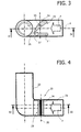
- the axis of oscillation 25 of the vane 24 constituting the throttle valve 23 is set at a distance from the axis A of the upstream branch 21 of the elbow portion 20 in such a way that, when the vane 24 is in its position of maximum closing of the duct (illustrated in Figure 3), in which one of its end edges enters into contact with the wall of the duct 23, the opposite edge of the wall 24, designated by 26, in any case leaves free for the passage of the air an area 27 that constitutes only a fraction of the entire section of the branch of duct 21, adjacent to the bottom wall 21b (with reference to the drawing).
- the vane 24 has a profile of a winged type so that, when it is inclined a little with respect to the axis A of the branch of duct 21 (see Figure 5c), the air flow that laps its two opposite faces tends to remain adherent to said faces so as to be deflected in the direction of the wall 21b.
- the provision of the device 19 upstream of the confluence 18 of the EGR duct 16 enables creation of a negative pressure, so closing the throttle valve 23, which increases the difference in pressure at the ends of the EGR duct 16. This enables recirculation of the exhaust gases in conditions in which the difference of pressure between the outlet of the particulate filter 10 and the inlet to the supercharger 5 would not normally be sufficient. Furthermore, it thus improves also the characteristic of regulation of the valve 17 set in the EGR duct 16.
- the device according to the invention enables imparting the whirling motion described above on the flow of the supply air, to the advantage of the efficiency of operation of the supercharging system.
- Figure 5 illustrates various positions for regulation of the vane 24 of the throttle valve 23.
- the vane 24 reaches the maximum inclination with respect to the axis A of the branch of duct 21 and consequently generates the maximum negative pressure.
- there is also obtained a maximum effect in the generation of the whirling movement thanks to the tangential introduction of the flow of air in the downstream branch 22 of the portion of duct 20 that takes to the supercharger.
- the gap 27 for passage of fluid is sized so as to ensure a negative pressure sufficient for the recirculation of the amount of gas desired in all the conditions of operation of the engine.
- Figure 6 shows a diagram that provides a possible criterion of use of the device according to the invention in a diesel engine.
- Each point of the plane of Figure 6 corresponds to a specific condition of operation of the engine, determined by a given value of rotation and by a given value of the effective mean pressure.
- the diagram is divided into areas (a), (b), (c) and (d) under a curve L indicating the condition of full load. Each area corresponds to the condition of operation designated by the same letter in Figure 5.
- the line E provides the limit of the conditions of operation in which recirculation of the exhaust gases occurs. As may be seen, at low load and at low speed of the engine the vane is in the position of maximum closing (a) and is displaced towards the condition of maximum opening as the load and speed increase.
- the device according to the invention enables the following benefits to be obtained:
- the device according to the invention presents the advantage of not entailing any increase in cost with respect to an engine equipped with a system for recirculation of gases at low pressure, as well as the advantage of enabling a convenient installation of the device.
- the engine according to the invention is provided with an electronic control unit which controls actuator means of any known type (not illustrated) that control opening of the throttle valve according to signals issued by sensors for detecting the engine r.p.m. and load, according to any predetermined logic, for example on the basis of a map of the type illustrated in Figure 6.
Landscapes
- Engineering & Computer Science (AREA)
- Chemical & Material Sciences (AREA)
- Combustion & Propulsion (AREA)
- Mechanical Engineering (AREA)
- General Engineering & Computer Science (AREA)
- Supercharger (AREA)
- Exhaust-Gas Circulating Devices (AREA)
- Control Of Throttle Valves Provided In The Intake System Or In The Exhaust System (AREA)
Abstract
Description
- The present invention relates to a device for imparting a movement of rotation (whirl) on the flow of air for supplying a turbo-supercharged internal-combustion engine, particularly of the type with recirculation of the exhaust gases upstream of the supercharger.
- A turbo-supercharged internal-combustion engine, with recirculation of the exhaust gases upstream of the supercharger, i.e., in the low-pressure stretch of the supply duct, has formed the subject of the preceding European patent application No. 04 425 279 filed in the name of the present applicant. In engines of this type, there is provided a throttle valve in the duct for supplying the air, upstream of the supercharger and upstream of the confluence of the duct for recirculation of the exhaust gases.
- A device as set forth in the preamble of
claim 1 is known from JP-A-60 047 818. A device for imparting a whirl to an air flow supplied to a turbo-supercharged internal-combustion engine is also known from DE 196 44 892. - A purpose of the present invention is to provide a device that will be able on the one hand to perform the function of partialization of the engine intake that is traditionally obtained with a throttle valve and on the other hand to impart on the flow of air at inlet to the supercharger a movement of rotation (whirl) or pre-rotation (pre-whirl) which enables an increase in the efficiency of operation of the supercharger.
- More in general, a purpose of the invention is to provide a device that is able to impart the aforesaid movement of whirl or pre-whirl on the flow of air for supplying an internal-combustion engine, also in the case, for example, where said engine is turbo-supercharged, but is not provided with an exhaust-gas-recirculation (EGR) system upstream of the supercharger.
- With a view to achieving these and further purposes, the invention is characterized by the features of
claim 1. - Thanks to said characteristic, when the throttle valve is slightly moved away from its position of maximum opening, it induces in any case a flow of the supply air converging towards a wall of the duct, which gives rise again to a slight swirl of the flow following upon the change of direction in the passage from the upstream branch to the downstream branch of the elbow portion.
- The above and further characteristics and advantages will emerge in any case more understandable in the light of the ensuing description with reference to the annexed plate of drawings, which are provided purely by way of non-limiting example, and in which:
- Figure 1 is a diagram of the system for supplying a turbo-supercharged diesel engine, with recirculation of the exhaust gases upstream of the supercharger, to which the device according to the invention is applied;
- Figure 2 is a schematic perspective view illustrating the working principle of the device according to the invention;
- Figures 3 and 4 are cross-sectional views of the device of Figure 2;
- Figure 5 is a schematic illustration of a series of different operating conditions of the device; and
- Figure 6 is a diagram illustrating a possible criterion of use of the device according to the invention.
- In Figure 1, the
reference number 1 designates as a whole a four-cylinder diesel engine, with anintake manifold 2 and anexhaust manifold 3. Theintake manifold 2 receives the supply air through a duct 4, in which there is set asupercharger 5. In the duct 4, upstream of thesupercharger 5 there is moreover set, in a way in itself known, a cooling device or intercooler 6. Theexhaust manifold 3 is connected to an exhaust piping 7, in which there are set: a turbine 8, which is connected mechanically by means of ashaft 9 to thesupercharger 5 for the purpose of driving it in rotation; and aparticulate filter 9. In the example illustrated, there are envisaged both asystem 11 for exhaust-gas recirculation according to a short route immediately upstream of theintake manifold 2 and asystem 12 for exhaust-gas recirculation according to a long route upstream of thesupercharger 5. Thesystem 11 comprises aduct 13, which is controlled by avalve 14 and in which there is set anintercooler 15. TheEGR system 12 comprises aduct 16 controlled by avalve 17. Theduct 13 sets the exhaust duct 7 directly in communication with the intake duct 4 upstream of themanifold 2, whilst theduct 16 causes recirculation of the exhaust gases, or a part thereof, at outlet from theparticulate filter 10 into the intake duct 4, upstream of thesupercharger 5. - Set in the intake duct 4, upstream of the
confluence 18 of theEGR duct 16 is adevice 19 according to the present invention. - Figure 2 is a schematic perspective view of the
device 19. Said device basically comprises an elbow portion ofduct 20, with anupstream branch 21, which in the example illustrated has a rectangular cross section, and adownstream branch 22, which in the example illustrated has a circular cross section. The twobranches upstream branch 21 there is moreover set athrottle valve 23 designed to partialize the section of passage of the flow of air through theupstream branch 21. In the example illustrated, thethrottle valve 23 has avane member 24, mounted oscillating like a rocker about anaxis 25, which is oriented transversely with respect to the direction of flow of the supply air to the inlet of thebranch 21 and which is orthogonal to twoopposite walls 21a of thebranch 21. As may be seen more clearly in Figure 3, the axis ofoscillation 25 of thevane 24 constituting thethrottle valve 23 is set at a distance from the axis A of theupstream branch 21 of theelbow portion 20 in such a way that, when thevane 24 is in its position of maximum closing of the duct (illustrated in Figure 3), in which one of its end edges enters into contact with the wall of theduct 23, the opposite edge of thewall 24, designated by 26, in any case leaves free for the passage of the air anarea 27 that constitutes only a fraction of the entire section of the branch ofduct 21, adjacent to thebottom wall 21b (with reference to the drawing). - Consequently, when the
throttle valve 23 is in its condition of maximum closing, upstream of the throttle valve there arrives a concentrated flow adjacent to thewall 21b and set at a distance from the axis A (Figures 2 and 3), which gives rise, as a result of the change of direction from thebranch 21 to the branch 22 (see Figure 2), to a rotary or whirling movement of the flow itself. Consequently, the air flow upstream of thethrottle valve 23 traverses thedownstream branch 22 according to a helical path, as indicated schematically by the arrows G in Figure 2. - According to a further important characteristic of the invention, the
vane 24 has a profile of a winged type so that, when it is inclined a little with respect to the axis A of the branch of duct 21 (see Figure 5c), the air flow that laps its two opposite faces tends to remain adherent to said faces so as to be deflected in the direction of thewall 21b. - The provision of the
device 19 upstream of theconfluence 18 of theEGR duct 16 enables creation of a negative pressure, so closing thethrottle valve 23, which increases the difference in pressure at the ends of theEGR duct 16. This enables recirculation of the exhaust gases in conditions in which the difference of pressure between the outlet of theparticulate filter 10 and the inlet to thesupercharger 5 would not normally be sufficient. Furthermore, it thus improves also the characteristic of regulation of thevalve 17 set in theEGR duct 16. - In addition to the advantage specified above, the device according to the invention enables imparting the whirling motion described above on the flow of the supply air, to the advantage of the efficiency of operation of the supercharging system.
- Figure 5 illustrates various positions for regulation of the
vane 24 of thethrottle valve 23. In the condition illustrated in Figure 5(a), thevane 24 reaches the maximum inclination with respect to the axis A of the branch ofduct 21 and consequently generates the maximum negative pressure. In said condition, there is also obtained a maximum effect in the generation of the whirling movement, thanks to the tangential introduction of the flow of air in thedownstream branch 22 of the portion ofduct 20 that takes to the supercharger. Thegap 27 for passage of fluid is sized so as to ensure a negative pressure sufficient for the recirculation of the amount of gas desired in all the conditions of operation of the engine. - In the condition illustrated in Figure 5(b), the top edge (as viewed in the figure) of the
vane 24 moves away from the corresponding wall of the duct so that the air is free to pass either below or above the vane. Since the inclination of thevane 24 with respect to the axis A remains considerable, the flow that laps the two opposite faces of the vane is "detached" with respect to the surface of the vane. The flow of air above the vane of course produces a decrease both in the effect of pre-whirl, and in the effect of suction pressure. - In the condition illustrated in Figure 5(c), in which the inclination of the
vane 24 with respect to the axis A becomes relatively small, the aerodynamic profile of thevane 24 enables the flow that laps its two opposite faces to remain adherent thereto. Consequently, there derives therefrom a deflection of the entire flow of air downwards (as viewed in the figure) in the direction of thewall 21b, with consequent increase of the effect of pre-whirl thus obtained, with respect to what occurs in the situation of Figure 5(b). In said condition, the resistance to the flow is reduced considerably. The greater the optimization of the profile of the vane, the smaller the drop in pressure with the pre-whirl generated. This operating mode is particularly interesting for those conditions of operation of the engine in which there is no recirculation of exhaust gases, so that negative pressure is not required, but in which the behaviour of the supercharger improves, increasing the level of pre-whirl. - Finally, in the condition illustrated in Figure 5(d), the
vane 24 is parallel to the axis A, so that there is obtained the minimum resistance to the flow and the total disappearance of the effect of pre-whirl, which on the other hand is not essential at high r.p.m. - Figure 6 shows a diagram that provides a possible criterion of use of the device according to the invention in a diesel engine. Each point of the plane of Figure 6 corresponds to a specific condition of operation of the engine, determined by a given value of rotation and by a given value of the effective mean pressure. The diagram is divided into areas (a), (b), (c) and (d) under a curve L indicating the condition of full load. Each area corresponds to the condition of operation designated by the same letter in Figure 5. The line E provides the limit of the conditions of operation in which recirculation of the exhaust gases occurs. As may be seen, at low load and at low speed of the engine the vane is in the position of maximum closing (a) and is displaced towards the condition of maximum opening as the load and speed increase. In the points of full load and at low speed, the motion of pre-whirl enables displacement, at higher values of the supercharging pressure, of the onset of surging phenomena in the supercharger. It is thus possible to supercharge to a greater extent with an increase in engine performance. As the speed rises, it is advisable to open the device gradually, i.e., reduce the angle of incidence of the vane, in order to contain the loss of head which grows on account of the increase in the flow rate. At full load, beyond 2000 r.p.m., the rotation of the air at inlet to the supercharger does not yield any further advantage.
- At the points of partial load, it is necessary to guarantee sufficient negative pressure for recirculating the amount of gas desired. The vane works then at wide angles (positions (a) and (b)). The pre-whirl generated by the device in these conditions enables at the same time improvement in the efficiency of the supercharger, reducing the work recovered in the turbine and consequently the counterpressure at the exhaust. This results in a reduction in fuel consumption and in emissions.
- As compared to the system previously proposed by the present applicant, which envisaged EGR upstream of the supercharger, i.e., in the low-pressure stretch of the supply duct, with a throttle valve at the inlet of the supercharger, the device according to the invention enables the following benefits to be obtained:
- increase in the performance of the engine at low r.p.m., principally thanks to the higher admissible supercharging pressures, without incurring in surging of the supercharger; and
- lower consumption at partial load on account of the increase in the efficiency of the supercharger, and potentially lower emissions on account of the reduction in the fuel introduced, associated to lower levels of consumption.
- As compared to other known devices that are able to generate whirling of the flow of supply air at the inlet of the supercharger, the device according to the invention presents the advantage of not entailing any increase in cost with respect to an engine equipped with a system for recirculation of gases at low pressure, as well as the advantage of enabling a convenient installation of the device.
- The engine according to the invention is provided with an electronic control unit which controls actuator means of any known type (not illustrated) that control opening of the throttle valve according to signals issued by sensors for detecting the engine r.p.m. and load, according to any predetermined logic, for example on the basis of a map of the type illustrated in Figure 6.
- Of course, without prejudice to the principle of the invention, the details of construction and the embodiments may vary widely with respect to what is described and illustrated herein purely by way of example, without thereby departing from the scope of the present invention.
Claims (5)
- A device for imparting a whirling motion on the flow of air (F) for supplying a turbo-supercharged internal-combustion engine, particularly of the type with exhaust-gas recirculation (EGR) upstream of the supercharger,
said device comprising :- an elbow-shaped portion of duct (20) for the supply air, with an upstream branch (21) and a downstream branch (22) forming an angle between them;- wherein said upstream branch (21) has a rectangular cross section, and said downstream branch (22) has a circular cross section and extends substantially orthogonal to the upstream branch, and- means for partializing the section of passage of the flow of air through said upstream branch (21), which is able to limit the section of passage of the fluid to an area (27) that constitutes only a fraction of the total section of duct, adjacent to a wall (21b) of the duct, in such a way that the downstream branch (22) of the aforesaid elbow portion (20) is reached by a localized tangential flow adjacent to a wall of the duct that is thus forced, as a result of the change in direction from the upstream branch to the downstream branch, to traverse said downstream branch according to a substantially helical path,- wherein said partializing means comprise a throttle valve (23) with a vane (24) mounted oscillating about an axis (25) in the upstream branch (21) of the aforesaid elbow portion (20) of duct,- wherein said axis of oscillation (25) of the vane (24) is orthogonal to two opposite walls (21a) of the aforesaid upstream branch (21) of the duct, and said axis of oscillation (25) is set at a distance from the central axis (A) of said upstream branch (21)characterized in that said valve (23) is a throttle valve pivotally mounted around said axis (25) in such a way that, when one end of the valve vane is in contact with a wall of the duct, the opposite end is set at a distance from the facing wall (21b) of the duct so as to leave free the aforesaid area of passage (27), and
in that said vane (24) has a profile of an aerodynamic wing, so that, when said vane (24) has a reduced inclination with respect to the axis (A) of said upstream branch (21), the flow of air that laps the two opposite faces of the vane tends to remain adherent thereto in such a way that the entire flow is deflected by the vane in the direction of a wall (21b) of the duct (21). - An internal-combustion engine, comprising a supercharger (5) interposed in a duct (4) for supplying the air to the engine, characterized in that it comprises a device according to claim 1 interposed in the supply duct (4) upstream of the supercharger (5).
- The internal-combustion engine according to Claim 2, characterized in that the aforesaid device is interposed in the supply duct (4) upstream of the confluence (18) of a duct (16) for recirculation of the exhaust gases.
- The engine according to Claim 3, characterized in that said EGR duct (16) branches off from an exhaust duct (7) of the engine, upstream of a turbine (8) for driving the supercharger (5) and upstream of a particulate filter (10).
- The engine according to Claim 2, characterized in that it is provided with an electronic control unit, which controls actuator means for controlling the aforesaid throttle valve according to signals indicating the engine r.p.m. and load and enables increase in the degree of opening of the throttle valve as the load and r.p.m. increase, according to a predetermined criterion.
Priority Applications (7)
| Application Number | Priority Date | Filing Date | Title |
|---|---|---|---|
| DE602004004676T DE602004004676T2 (en) | 2004-12-30 | 2004-12-30 | Device for generating a rotational movement of the air flow supplied to a supercharged internal combustion engine |
| EP04425961A EP1676995B1 (en) | 2004-12-30 | 2004-12-30 | Device for imparting a movement of rotation to the air flow fed to a turbo-charged internal combustion engine |
| ES04425961T ES2280934T3 (en) | 2004-12-30 | 2004-12-30 | DEVICE FOR IMPROVING A ROTATION MOVEMENT TO THE POWERED AIR FLOW TO AN INTERNAL COMBUSTION ENGINE TURBO. |
| AT04425961T ATE353401T1 (en) | 2004-12-30 | 2004-12-30 | DEVICE FOR PRODUCING A ROTATIONAL MOTION OF THE AIR FLOW SUPPLIED TO A CHARGED INTERNAL COMBUSTION ENGINE |
| JP2005371848A JP4571072B2 (en) | 2004-12-30 | 2005-12-26 | Device for imparting a swirling motion to an air flow to provide a turbocharged internal combustion engine |
| US11/319,213 US7322191B2 (en) | 2004-12-30 | 2005-12-28 | Device for imparting a whirling motion on the flow of air for supplying a turbo-supercharged internal-combustion engine |
| US12/007,862 US7690200B2 (en) | 2004-12-30 | 2008-01-16 | Device for imparting a whirling motion on the flow of air for supplying a turbo-supercharged internal-combustion engine |
Applications Claiming Priority (1)
| Application Number | Priority Date | Filing Date | Title |
|---|---|---|---|
| EP04425961A EP1676995B1 (en) | 2004-12-30 | 2004-12-30 | Device for imparting a movement of rotation to the air flow fed to a turbo-charged internal combustion engine |
Publications (2)
| Publication Number | Publication Date |
|---|---|
| EP1676995A1 EP1676995A1 (en) | 2006-07-05 |
| EP1676995B1 true EP1676995B1 (en) | 2007-02-07 |
Family
ID=34932969
Family Applications (1)
| Application Number | Title | Priority Date | Filing Date |
|---|---|---|---|
| EP04425961A Expired - Lifetime EP1676995B1 (en) | 2004-12-30 | 2004-12-30 | Device for imparting a movement of rotation to the air flow fed to a turbo-charged internal combustion engine |
Country Status (6)
| Country | Link |
|---|---|
| US (2) | US7322191B2 (en) |
| EP (1) | EP1676995B1 (en) |
| JP (1) | JP4571072B2 (en) |
| AT (1) | ATE353401T1 (en) |
| DE (1) | DE602004004676T2 (en) |
| ES (1) | ES2280934T3 (en) |
Families Citing this family (23)
| Publication number | Priority date | Publication date | Assignee | Title |
|---|---|---|---|---|
| DE102004040893A1 (en) * | 2004-08-24 | 2006-03-02 | Bayerische Motoren Werke Ag | turbocharger |
| US7380400B2 (en) * | 2005-10-06 | 2008-06-03 | Ford Global Technologies, Llc | System and method for high pressure and low pressure exhaust gas recirculation control and estimation |
| FR2911635B1 (en) * | 2007-01-24 | 2009-10-23 | Peugeot Citroen Automobiles Sa | THERMAL MOTOR EQUIPPED WITH A TURBOCHARGER AND TWO EXHAUST GAS RECIRCULATION CIRCUITS OF HIGH PRESSURE AND LOW PRESSURE TYPE. |
| CN101578439B (en) * | 2007-02-05 | 2011-11-16 | 博格华纳公司 | Turbocharger |
| JP2008248729A (en) * | 2007-03-29 | 2008-10-16 | Honda Motor Co Ltd | EGR control device for internal combustion engine |
| DE202007005986U1 (en) * | 2007-04-24 | 2008-09-04 | Mann+Hummel Gmbh | Combustion air and exhaust gas arrangement of an internal combustion engine |
| EP2131025A1 (en) * | 2008-06-06 | 2009-12-09 | General Electric Company | Intake channels for internal combustion engines |
| US8177498B2 (en) | 2009-04-21 | 2012-05-15 | Ford Global Technologies, Llc | Inlet swirl control for turbochargers |
| US9010111B2 (en) * | 2009-04-29 | 2015-04-21 | Fev Gmbh | Compressor comprising a swirl generator, for a motor vehicle |
| US8915235B2 (en) | 2011-06-28 | 2014-12-23 | Caterpillar Inc. | Mixing system for engine with exhaust gas recirculation |
| AT512332B1 (en) * | 2011-12-23 | 2021-01-15 | MAN TRUCK & BUS OESTERREICH GesmbH | ARRANGEMENT OF A THROTTLE DEVICE FOR CONTROLLING AND / OR REGULATING THE MOTOR BRAKING OPERATION |
| US20130269349A1 (en) * | 2012-04-16 | 2013-10-17 | General Electric Company | System and method for recirculating a vented fuel to a fuel delivery system |
| US10125793B2 (en) | 2013-02-22 | 2018-11-13 | Mitsubishi Heavy Industries, Ltd. | Centrifugal compressor |
| US8960166B2 (en) | 2013-06-03 | 2015-02-24 | Ford Global Technologies, Llc | Systems and methods for heating a pre-compressor duct to reduce condensate formation |
| US20160097351A1 (en) * | 2014-10-07 | 2016-04-07 | Borgwarner Inc. | Swirl type lp - egr throttle mechanism |
| KR101704239B1 (en) * | 2015-07-27 | 2017-02-07 | 현대자동차주식회사 | Device for mixing EGR gas and fresh air |
| FR3069022B1 (en) * | 2017-07-11 | 2021-05-21 | Renault Sas | CONTROL PROCESS OF A SUPERCHARGED INTERNAL COMBUSTION ENGINE. |
| US20190040824A1 (en) * | 2017-08-03 | 2019-02-07 | GM Global Technology Operations LLC | Long route-egr connection for compressor inlet swirl control |
| CN110360000B (en) * | 2018-04-09 | 2021-08-17 | 上海汽车集团股份有限公司 | Intake Control Method of Direct Injection Gasoline Engine |
| JP7268353B2 (en) * | 2018-12-28 | 2023-05-08 | セイコーエプソン株式会社 | Swirling flow forming device and deposition device |
| US11208971B2 (en) * | 2019-01-16 | 2021-12-28 | Ford Global Technologies, Llc | Methods and systems for mitigating condensate formation |
| WO2021171410A1 (en) * | 2020-02-26 | 2021-09-02 | 三菱重工エンジン&ターボチャージャ株式会社 | Supercharger |
| US11592041B2 (en) * | 2020-10-28 | 2023-02-28 | Artisan Industries, Inc. | Device for increasing flow capacity of a fluid channel |
Family Cites Families (21)
| Publication number | Priority date | Publication date | Assignee | Title |
|---|---|---|---|---|
| US1857070A (en) * | 1930-11-18 | 1932-05-03 | Fred W Lee | Carburetor |
| US3926215A (en) * | 1973-08-03 | 1975-12-16 | Nat Res Dev | Fluid control valves |
| AT343957B (en) * | 1972-09-15 | 1977-10-15 | List Hans | INLET CHANNEL FOR COMBUSTION ENGINES, IN PARTICULAR DIESEL ENGINES |
| US3838940A (en) * | 1972-09-20 | 1974-10-01 | Kaman Aerospace Corp | Deployable rotor |
| US4194722A (en) * | 1977-10-11 | 1980-03-25 | International Telephone And Telegraph Corporation | Butterfly valve having high performance disc |
| DE2803533A1 (en) * | 1978-01-27 | 1979-08-02 | Volkswagenwerk Ag | AIR COMPRESSING, SELF-IGNING COMBUSTION ENGINE |
| US4577602A (en) * | 1979-06-11 | 1986-03-25 | Automotive Engine Associates | High swirl very low pollution piston engine employing optimizable vorticity metering |
| JPS5854246B2 (en) * | 1980-09-29 | 1983-12-03 | マツダ株式会社 | Intake system for turbocharged engine |
| JPS6047818A (en) * | 1983-08-24 | 1985-03-15 | Toyota Motor Corp | Intake port for internal-combustion engine |
| GB2242228A (en) * | 1990-03-24 | 1991-09-25 | Rover Group | I.c engine charge swirl inlet arrangement |
| DE4213047A1 (en) * | 1992-04-21 | 1993-10-28 | Kuehnle Kopp Kausch Ag | Radial compressor for vehicle exhaust gas turbocharger - uses feed pipe to deliver flow medium to influence conditions in circulation chamber |
| KR100205995B1 (en) * | 1994-12-28 | 1999-07-01 | 정몽규 | Variable intake system for an internal combustion engine |
| DE19644892A1 (en) * | 1996-10-29 | 1998-04-30 | Johannes Werner | Intake control for turbo machines and IC engines |
| US5979401A (en) * | 1998-08-10 | 1999-11-09 | Ford Global Technologies, Inc. | Internal combustion engine having induction system with aerodynamic charge motion control valve |
| US6606975B1 (en) * | 2000-10-04 | 2003-08-19 | Ford Global Technologies, Llc | Passive turbulence control assembly and a method for creating turbulence |
| FR2827907A1 (en) * | 2001-07-26 | 2003-01-31 | Patrice Harduin | Anti-pollution system for diesel engines has air flow regulator at inlet to compressor |
| SE524706C2 (en) * | 2002-06-03 | 2004-09-21 | Stt Emtec Ab | Apparatus and process for the purification of exhaust gases and the use of the device in a diesel engine |
| JP4089396B2 (en) * | 2002-11-15 | 2008-05-28 | いすゞ自動車株式会社 | EGR system for internal combustion engine with turbocharger |
| JP4155397B2 (en) * | 2003-02-12 | 2008-09-24 | 日産ディーゼル工業株式会社 | Exhaust gas recirculation control device for supercharged engine |
| JP4182770B2 (en) * | 2003-02-14 | 2008-11-19 | トヨタ自動車株式会社 | diesel engine |
| DE602004001578T2 (en) | 2004-04-21 | 2007-07-19 | C.R.F. Società Consortile per Azioni, Orbassano | Turbocharged diesel engine with long-term exhaust gas recirculation system |
-
2004
- 2004-12-30 DE DE602004004676T patent/DE602004004676T2/en not_active Expired - Lifetime
- 2004-12-30 AT AT04425961T patent/ATE353401T1/en not_active IP Right Cessation
- 2004-12-30 EP EP04425961A patent/EP1676995B1/en not_active Expired - Lifetime
- 2004-12-30 ES ES04425961T patent/ES2280934T3/en not_active Expired - Lifetime
-
2005
- 2005-12-26 JP JP2005371848A patent/JP4571072B2/en not_active Expired - Fee Related
- 2005-12-28 US US11/319,213 patent/US7322191B2/en not_active Expired - Fee Related
-
2008
- 2008-01-16 US US12/007,862 patent/US7690200B2/en not_active Expired - Fee Related
Also Published As
| Publication number | Publication date |
|---|---|
| US7690200B2 (en) | 2010-04-06 |
| US20080149207A1 (en) | 2008-06-26 |
| US20060156723A1 (en) | 2006-07-20 |
| US7322191B2 (en) | 2008-01-29 |
| DE602004004676T2 (en) | 2007-11-08 |
| EP1676995A1 (en) | 2006-07-05 |
| DE602004004676D1 (en) | 2007-03-22 |
| JP2006189049A (en) | 2006-07-20 |
| JP4571072B2 (en) | 2010-10-27 |
| ES2280934T3 (en) | 2007-09-16 |
| ATE353401T1 (en) | 2007-02-15 |
Similar Documents
| Publication | Publication Date | Title |
|---|---|---|
| US7690200B2 (en) | Device for imparting a whirling motion on the flow of air for supplying a turbo-supercharged internal-combustion engine | |
| CN1573045B (en) | Turbocharged engine | |
| JP4215069B2 (en) | Exhaust gas recirculation device for internal combustion engine | |
| JP2012500356A (en) | Internal combustion engine with exhaust turbocharger | |
| WO2007136142A1 (en) | Exhaust gas recirculation system of internal combustion engine | |
| CN106401762B (en) | Supercharger with exhaust gas recirculation | |
| JPH01318720A (en) | Supercharging internal combustion engine | |
| CN104005838A (en) | Supercharged internal combustion engine with two-channel turbine and method for operating an internal combustion engine of said type | |
| US20100178164A1 (en) | System and method for turbocharging an engine | |
| JP5596709B2 (en) | Method and apparatus for controlling turbine efficiency | |
| JPS6026185Y2 (en) | Internal combustion engine intake system | |
| JP6394624B2 (en) | Turbocharged engine | |
| US10697358B2 (en) | Intake passage structure for turbocharger-equipped engine | |
| RU2704592C1 (en) | Control method and control device for internal combustion engine | |
| CN109595085B (en) | Control device for internal combustion engine | |
| JP2010216365A (en) | Supercharging system for internal combustion engine | |
| JP5280113B2 (en) | Exhaust gas recirculation device in a multi-cylinder internal combustion engine | |
| JP5573701B2 (en) | Internal combustion engine | |
| JPWO2018069975A1 (en) | Intake passage structure of a turbocharged engine | |
| JP6907977B2 (en) | Turbocharger controller | |
| JP2995200B2 (en) | Engine air supply | |
| CN105358806B (en) | engine control equipment | |
| JPH07233761A (en) | Engine exhaust gas recirculation system | |
| JPS633376Y2 (en) | ||
| JP2000110628A (en) | Control device for supercharged engine |
Legal Events
| Date | Code | Title | Description |
|---|---|---|---|
| PUAI | Public reference made under article 153(3) epc to a published international application that has entered the european phase |
Free format text: ORIGINAL CODE: 0009012 |
|
| 17P | Request for examination filed |
Effective date: 20051011 |
|
| AK | Designated contracting states |
Kind code of ref document: A1 Designated state(s): AT BE BG CH CY CZ DE DK EE ES FI FR GB GR HU IE IS IT LI LT LU MC NL PL PT RO SE SI SK TR |
|
| AX | Request for extension of the european patent |
Extension state: AL BA HR LV MK YU |
|
| GRAP | Despatch of communication of intention to grant a patent |
Free format text: ORIGINAL CODE: EPIDOSNIGR1 |
|
| GRAS | Grant fee paid |
Free format text: ORIGINAL CODE: EPIDOSNIGR3 |
|
| GRAA | (expected) grant |
Free format text: ORIGINAL CODE: 0009210 |
|
| AK | Designated contracting states |
Kind code of ref document: B1 Designated state(s): AT BE BG CH CY CZ DE DK EE ES FI FR GB GR HU IE IS IT LI LT LU MC NL PL PT RO SE SI SK TR |
|
| PG25 | Lapsed in a contracting state [announced via postgrant information from national office to epo] |
Ref country code: PL Free format text: LAPSE BECAUSE OF FAILURE TO SUBMIT A TRANSLATION OF THE DESCRIPTION OR TO PAY THE FEE WITHIN THE PRESCRIBED TIME-LIMIT Effective date: 20070207 Ref country code: SI Free format text: LAPSE BECAUSE OF FAILURE TO SUBMIT A TRANSLATION OF THE DESCRIPTION OR TO PAY THE FEE WITHIN THE PRESCRIBED TIME-LIMIT Effective date: 20070207 Ref country code: BE Free format text: LAPSE BECAUSE OF FAILURE TO SUBMIT A TRANSLATION OF THE DESCRIPTION OR TO PAY THE FEE WITHIN THE PRESCRIBED TIME-LIMIT Effective date: 20070207 Ref country code: NL Free format text: LAPSE BECAUSE OF FAILURE TO SUBMIT A TRANSLATION OF THE DESCRIPTION OR TO PAY THE FEE WITHIN THE PRESCRIBED TIME-LIMIT Effective date: 20070207 Ref country code: CH Free format text: LAPSE BECAUSE OF FAILURE TO SUBMIT A TRANSLATION OF THE DESCRIPTION OR TO PAY THE FEE WITHIN THE PRESCRIBED TIME-LIMIT Effective date: 20070207 Ref country code: LI Free format text: LAPSE BECAUSE OF FAILURE TO SUBMIT A TRANSLATION OF THE DESCRIPTION OR TO PAY THE FEE WITHIN THE PRESCRIBED TIME-LIMIT Effective date: 20070207 Ref country code: FI Free format text: LAPSE BECAUSE OF FAILURE TO SUBMIT A TRANSLATION OF THE DESCRIPTION OR TO PAY THE FEE WITHIN THE PRESCRIBED TIME-LIMIT Effective date: 20070207 Ref country code: AT Free format text: LAPSE BECAUSE OF FAILURE TO SUBMIT A TRANSLATION OF THE DESCRIPTION OR TO PAY THE FEE WITHIN THE PRESCRIBED TIME-LIMIT Effective date: 20070207 Ref country code: DK Free format text: LAPSE BECAUSE OF FAILURE TO SUBMIT A TRANSLATION OF THE DESCRIPTION OR TO PAY THE FEE WITHIN THE PRESCRIBED TIME-LIMIT Effective date: 20070207 |
|
| REG | Reference to a national code |
Ref country code: GB Ref legal event code: FG4D |
|
| REG | Reference to a national code |
Ref country code: CH Ref legal event code: EP |
|
| REG | Reference to a national code |
Ref country code: IE Ref legal event code: FG4D |
|
| AKX | Designation fees paid |
Designated state(s): AT BE BG CH CY CZ DE DK EE ES FI FR GB GR HU IE IS IT LI LT LU MC NL PL PT RO SE SI SK TR |
|
| REF | Corresponds to: |
Ref document number: 602004004676 Country of ref document: DE Date of ref document: 20070322 Kind code of ref document: P |
|
| PG25 | Lapsed in a contracting state [announced via postgrant information from national office to epo] |
Ref country code: BG Free format text: LAPSE BECAUSE OF FAILURE TO SUBMIT A TRANSLATION OF THE DESCRIPTION OR TO PAY THE FEE WITHIN THE PRESCRIBED TIME-LIMIT Effective date: 20070507 |
|
| REG | Reference to a national code |
Ref country code: SE Ref legal event code: TRGR |
|
| PG25 | Lapsed in a contracting state [announced via postgrant information from national office to epo] |
Ref country code: IS Free format text: LAPSE BECAUSE OF FAILURE TO SUBMIT A TRANSLATION OF THE DESCRIPTION OR TO PAY THE FEE WITHIN THE PRESCRIBED TIME-LIMIT Effective date: 20070607 |
|
| PG25 | Lapsed in a contracting state [announced via postgrant information from national office to epo] |
Ref country code: PT Free format text: LAPSE BECAUSE OF FAILURE TO SUBMIT A TRANSLATION OF THE DESCRIPTION OR TO PAY THE FEE WITHIN THE PRESCRIBED TIME-LIMIT Effective date: 20070709 |
|
| NLV1 | Nl: lapsed or annulled due to failure to fulfill the requirements of art. 29p and 29m of the patents act | ||
| ET | Fr: translation filed | ||
| REG | Reference to a national code |
Ref country code: CH Ref legal event code: PL |
|
| REG | Reference to a national code |
Ref country code: ES Ref legal event code: FG2A Ref document number: 2280934 Country of ref document: ES Kind code of ref document: T3 |
|
| PG25 | Lapsed in a contracting state [announced via postgrant information from national office to epo] |
Ref country code: SK Free format text: LAPSE BECAUSE OF FAILURE TO SUBMIT A TRANSLATION OF THE DESCRIPTION OR TO PAY THE FEE WITHIN THE PRESCRIBED TIME-LIMIT Effective date: 20070207 |
|
| PLBE | No opposition filed within time limit |
Free format text: ORIGINAL CODE: 0009261 |
|
| STAA | Information on the status of an ep patent application or granted ep patent |
Free format text: STATUS: NO OPPOSITION FILED WITHIN TIME LIMIT |
|
| PG25 | Lapsed in a contracting state [announced via postgrant information from national office to epo] |
Ref country code: RO Free format text: LAPSE BECAUSE OF FAILURE TO SUBMIT A TRANSLATION OF THE DESCRIPTION OR TO PAY THE FEE WITHIN THE PRESCRIBED TIME-LIMIT Effective date: 20070207 Ref country code: CZ Free format text: LAPSE BECAUSE OF FAILURE TO SUBMIT A TRANSLATION OF THE DESCRIPTION OR TO PAY THE FEE WITHIN THE PRESCRIBED TIME-LIMIT Effective date: 20070207 |
|
| 26N | No opposition filed |
Effective date: 20071108 |
|
| PG25 | Lapsed in a contracting state [announced via postgrant information from national office to epo] |
Ref country code: LT Free format text: LAPSE BECAUSE OF FAILURE TO SUBMIT A TRANSLATION OF THE DESCRIPTION OR TO PAY THE FEE WITHIN THE PRESCRIBED TIME-LIMIT Effective date: 20070207 |
|
| PG25 | Lapsed in a contracting state [announced via postgrant information from national office to epo] |
Ref country code: GR Free format text: LAPSE BECAUSE OF FAILURE TO SUBMIT A TRANSLATION OF THE DESCRIPTION OR TO PAY THE FEE WITHIN THE PRESCRIBED TIME-LIMIT Effective date: 20070508 |
|
| PG25 | Lapsed in a contracting state [announced via postgrant information from national office to epo] |
Ref country code: MC Free format text: LAPSE BECAUSE OF NON-PAYMENT OF DUE FEES Effective date: 20071231 |
|
| EUG | Se: european patent has lapsed | ||
| PG25 | Lapsed in a contracting state [announced via postgrant information from national office to epo] |
Ref country code: IE Free format text: LAPSE BECAUSE OF NON-PAYMENT OF DUE FEES Effective date: 20071231 Ref country code: SE Free format text: LAPSE BECAUSE OF NON-PAYMENT OF DUE FEES Effective date: 20071231 |
|
| PG25 | Lapsed in a contracting state [announced via postgrant information from national office to epo] |
Ref country code: EE Free format text: LAPSE BECAUSE OF FAILURE TO SUBMIT A TRANSLATION OF THE DESCRIPTION OR TO PAY THE FEE WITHIN THE PRESCRIBED TIME-LIMIT Effective date: 20070207 |
|
| REG | Reference to a national code |
Ref country code: ES Ref legal event code: FD2A Effective date: 20071231 |
|
| PG25 | Lapsed in a contracting state [announced via postgrant information from national office to epo] |
Ref country code: ES Free format text: LAPSE BECAUSE OF NON-PAYMENT OF DUE FEES Effective date: 20071231 |
|
| PG25 | Lapsed in a contracting state [announced via postgrant information from national office to epo] |
Ref country code: CY Free format text: LAPSE BECAUSE OF FAILURE TO SUBMIT A TRANSLATION OF THE DESCRIPTION OR TO PAY THE FEE WITHIN THE PRESCRIBED TIME-LIMIT Effective date: 20070207 |
|
| GBPC | Gb: european patent ceased through non-payment of renewal fee |
Effective date: 20081230 |
|
| PG25 | Lapsed in a contracting state [announced via postgrant information from national office to epo] |
Ref country code: LU Free format text: LAPSE BECAUSE OF NON-PAYMENT OF DUE FEES Effective date: 20071230 |
|
| PG25 | Lapsed in a contracting state [announced via postgrant information from national office to epo] |
Ref country code: HU Free format text: LAPSE BECAUSE OF FAILURE TO SUBMIT A TRANSLATION OF THE DESCRIPTION OR TO PAY THE FEE WITHIN THE PRESCRIBED TIME-LIMIT Effective date: 20070808 Ref country code: TR Free format text: LAPSE BECAUSE OF FAILURE TO SUBMIT A TRANSLATION OF THE DESCRIPTION OR TO PAY THE FEE WITHIN THE PRESCRIBED TIME-LIMIT Effective date: 20070207 |
|
| PG25 | Lapsed in a contracting state [announced via postgrant information from national office to epo] |
Ref country code: GB Free format text: LAPSE BECAUSE OF NON-PAYMENT OF DUE FEES Effective date: 20081230 |
|
| REG | Reference to a national code |
Ref country code: FR Ref legal event code: PLFP Year of fee payment: 12 |
|
| REG | Reference to a national code |
Ref country code: FR Ref legal event code: PLFP Year of fee payment: 13 |
|
| REG | Reference to a national code |
Ref country code: FR Ref legal event code: PLFP Year of fee payment: 14 |
|
| PGFP | Annual fee paid to national office [announced via postgrant information from national office to epo] |
Ref country code: FR Payment date: 20171226 Year of fee payment: 14 |
|
| PGFP | Annual fee paid to national office [announced via postgrant information from national office to epo] |
Ref country code: IT Payment date: 20171212 Year of fee payment: 14 |
|
| PGFP | Annual fee paid to national office [announced via postgrant information from national office to epo] |
Ref country code: DE Payment date: 20180228 Year of fee payment: 14 |
|
| REG | Reference to a national code |
Ref country code: DE Ref legal event code: R119 Ref document number: 602004004676 Country of ref document: DE |
|
| PG25 | Lapsed in a contracting state [announced via postgrant information from national office to epo] |
Ref country code: DE Free format text: LAPSE BECAUSE OF NON-PAYMENT OF DUE FEES Effective date: 20190702 Ref country code: IT Free format text: LAPSE BECAUSE OF NON-PAYMENT OF DUE FEES Effective date: 20181230 Ref country code: FR Free format text: LAPSE BECAUSE OF NON-PAYMENT OF DUE FEES Effective date: 20181231 |