US1857070A - Carburetor - Google Patents
Carburetor Download PDFInfo
- Publication number
- US1857070A US1857070A US496541A US49654130A US1857070A US 1857070 A US1857070 A US 1857070A US 496541 A US496541 A US 496541A US 49654130 A US49654130 A US 49654130A US 1857070 A US1857070 A US 1857070A
- Authority
- US
- United States
- Prior art keywords
- passage
- air
- ring
- carburetor
- fins
- Prior art date
- Legal status (The legal status is an assumption and is not a legal conclusion. Google has not performed a legal analysis and makes no representation as to the accuracy of the status listed.)
- Expired - Lifetime
Links
Images

Classifications
-
- F—MECHANICAL ENGINEERING; LIGHTING; HEATING; WEAPONS; BLASTING
- F02—COMBUSTION ENGINES; HOT-GAS OR COMBUSTION-PRODUCT ENGINE PLANTS
- F02M—SUPPLYING COMBUSTION ENGINES IN GENERAL WITH COMBUSTIBLE MIXTURES OR CONSTITUENTS THEREOF
- F02M29/00—Apparatus for re-atomising condensed fuel or homogenising fuel-air mixture
- F02M29/04—Apparatus for re-atomising condensed fuel or homogenising fuel-air mixture having screens, gratings, baffles or the like
- F02M29/06—Apparatus for re-atomising condensed fuel or homogenising fuel-air mixture having screens, gratings, baffles or the like generating whirling motion of mixture
-
- F—MECHANICAL ENGINEERING; LIGHTING; HEATING; WEAPONS; BLASTING
- F02—COMBUSTION ENGINES; HOT-GAS OR COMBUSTION-PRODUCT ENGINE PLANTS
- F02M—SUPPLYING COMBUSTION ENGINES IN GENERAL WITH COMBUSTIBLE MIXTURES OR CONSTITUENTS THEREOF
- F02M1/00—Carburettors with means for facilitating engine's starting or its idling below operational temperatures
- F02M1/02—Carburettors with means for facilitating engine's starting or its idling below operational temperatures the means to facilitate starting or idling being chokes for enriching fuel-air mixture
-
- F—MECHANICAL ENGINEERING; LIGHTING; HEATING; WEAPONS; BLASTING
- F02—COMBUSTION ENGINES; HOT-GAS OR COMBUSTION-PRODUCT ENGINE PLANTS
- F02M—SUPPLYING COMBUSTION ENGINES IN GENERAL WITH COMBUSTIBLE MIXTURES OR CONSTITUENTS THEREOF
- F02M19/00—Details, component parts, or accessories of carburettors, not provided for in, or of interest apart from, the apparatus of groups F02M1/00 - F02M17/00
- F02M19/08—Venturis
- F02M19/088—Whirl devices and other atomising means in or on the venturi walls
-
- F—MECHANICAL ENGINEERING; LIGHTING; HEATING; WEAPONS; BLASTING
- F02—COMBUSTION ENGINES; HOT-GAS OR COMBUSTION-PRODUCT ENGINE PLANTS
- F02B—INTERNAL-COMBUSTION PISTON ENGINES; COMBUSTION ENGINES IN GENERAL
- F02B33/00—Engines characterised by provision of pumps for charging or scavenging
- F02B33/32—Engines with pumps other than of reciprocating-piston type
-
- F—MECHANICAL ENGINEERING; LIGHTING; HEATING; WEAPONS; BLASTING
- F02—COMBUSTION ENGINES; HOT-GAS OR COMBUSTION-PRODUCT ENGINE PLANTS
- F02M—SUPPLYING COMBUSTION ENGINES IN GENERAL WITH COMBUSTIBLE MIXTURES OR CONSTITUENTS THEREOF
- F02M2700/00—Supplying, feeding or preparing air, fuel, fuel air mixtures or auxiliary fluids for a combustion engine; Use of exhaust gas; Compressors for piston engines
- F02M2700/43—Arrangements for supplying air, fuel or auxiliary fluids to a combustion space of mixture compressing engines working with liquid fuel
- F02M2700/4302—Arrangements for supplying air, fuel or auxiliary fluids to a combustion space of mixture compressing engines working with liquid fuel whereby air and fuel are sucked into the mixture conduit
- F02M2700/4373—Mixture improving devices
- F02M2700/4376—Mechanical devices
-
- F—MECHANICAL ENGINEERING; LIGHTING; HEATING; WEAPONS; BLASTING
- F02—COMBUSTION ENGINES; HOT-GAS OR COMBUSTION-PRODUCT ENGINE PLANTS
- F02M—SUPPLYING COMBUSTION ENGINES IN GENERAL WITH COMBUSTIBLE MIXTURES OR CONSTITUENTS THEREOF
- F02M35/00—Combustion-air cleaners, air intakes, intake silencers, or induction systems specially adapted for, or arranged on, internal-combustion engines
- F02M35/10—Air intakes; Induction systems
- F02M35/10006—Air intakes; Induction systems characterised by the position of elements of the air intake system in direction of the air intake flow, i.e. between ambient air inlet and supply to the combustion chamber
- F02M35/10026—Plenum chambers
- F02M35/10059—Swirl chamber upstream of the plenum chamber
Definitions
- This invention relates to a device for intimately mixing a liquid anda gas and more particularly to the type of'mixers known as carburetors, which are extensively used on internal combustion engines for automobiles, for mixing a liquid fuel such as gasoline with a gas suchas air with which it will explosively react under proper conditions.
- carburetors which are extensively used on internal combustion engines for automobiles, for mixing a liquid fuel such as gasoline with a gas suchas air with which it will explosively react under proper conditions.
- the explosive mixture used by internal combustion engines produces its maximum effect only when the percentage of fuel in the explosive mixture is exactly right for the particular speed at which the engine is operating and that the same mixture will not give maximum power at all speeds.
- 3 With a system of 30 carburetion such as is in'general use it is the usual practice to adjust or-proportion' the fuel nozzles so that a proper amount of fuel is injected into the airto give maximum efficiency at the average running speed, With such systemsthere is no assurance nor any reason to believe that the proper mixture will be supplied to theengine over any appreciable range of speeds; The fact that a proper mixture is not supplied to the engine at all times is clearly shown by the fact that fre-, quently when the engine is running at an idling speed and the butterfly valve is quickly opened, the engine will' stall because an improperly proportioned mixture has been supplied thereto.
- the passage in which the dispersion is made has been formed into the shape of aVenturi tube, that is with a smaller orv constricted section which tapers gradually intoa section-of larger cross section or diameter.
- the nozzles from which the fuel is dispersed or atomized are then located nearthe smallest part of the constriction and as the expansion of the airon pass.- ing the constrictionincreases the suction upon these nozzles they mayconsequently be made smaller: and still supply the'same amount-of fuel. It has been found that these smaller nozzles to gether'with the expansion of-the air cause a more intimate mixture of the air and fuel and consequently a better and more powerful explosive mixture.
- the present invention relates primarilyto a means for obtaining an intimate-mixture of air and liquid fuel and tosuch means as will also insure that the proportion of dispersed'fuel in the explosive mixture will at all times be exactly thatrequired for maximum efficiency regardless of the speed at which the engine is running. This is accomplished by a novel construction of that section of the passage through which the air or other gas travels before it reaches the manually operated butterfly valve and in which section of the passage the gasoline or other fuel .is atomized or dispersed in the air. 7
- sage is divided into two parts, a part of when nozzles when air is passed therethrough and the supplemental openings converge towards the center of the" passage, 'lthus directing streams ofair into the fuel and .airmixtur'e and causing a thorough "intermixing as well as addihgto vthesu'et-ion effect upon the nozzles.
- flanges do not'extehd vertically but spiral around the axis ofthe ring helically.
- the passage in which the ring is situated maybe slightly smaller on theoutlet side of the ring'and taper to-this smaller diameter immediately above the ring or a slight constriction may be formed in the passagewayimmediately'above thering.
- Supplemental jets of air are formed the pasageways between the radial fins on the ring and are given a whirl.- ing motio-n by these fins and an inwardly directed motion by the tapered wall or constrict-ion of the passage and thus add to the suction over the nozzles and assist greatly in mining the air'and fuel.
- the number and spacing of these fins on this ring and conse quently the resistance offered to the air flowing therethrough may be varied towary the mixture which the carburetor will form and the number of fins on the dili erent sides of the ring may likewise be variedin order to will tend to pass through the of ⁇ the ring andconsequently a greater amen-int of air 1 which is closest to the eiitrance passage.
- This eifect may be balaglcedby placing more fins r wider fins on this side of .the ring and hence limiting the area of the openings.
- applicants invention also includes, when desirable, the provision e semp et y s a ate Pa g in th a buretor whereby the air which is supplied to the central opening in the ring is supplied from a completely different source than that which supplies the air to the supplemental openings around the periphery.
- This comprises a passageway leading from the opening in the center of the ringdirectly through the bottom of the carburetor and the original passageway is h left to pp y the upplementa aren'- ings only.
- This type of carburetor is also particularly adapted to be used with air supplied under pressure by a supercharger which may be connected to either or-both of the passageways but preferably to the passageway supplying the supplemental openings and in this case it is often found advisable to place a valve in the passageway leading to the central opening in order to control the amount of air entering that opening and hence the amount of fuel supplied tojthe mixture.
- a super-charger in such a construction is preferably controlled in some suitable manner so as not to blow air back through the central opening when the butterfly valve is closed.
- the supercharger may also be used with a carburetor of the construction first described in which case all of the air is fed to the carburetor under pressure.
- Fig. 1 illustrates a carburetor of the applicants improved type shown in side elevation with certain parts in cross section;
- Fig. 2 is a top sectional view of the same construct-ion taken on the line 22 of Fig. 1.
- Fig. 3 is a perspective view of the ring which causes the mixing of" the fuel and air and replaces the old Venturi tube.
- Fig. 4 illustrates a modified form; of the applicants invention being a side'elevational view with certain parts in cross section.
- Fig. 5 shows a cross section of apart of this new construction taken on the line 55 of Fig. 4- and looking downward.
- Fig. 6 is a bottom view of the modification" of the carburetor shown in Fig.- 4. a
- Fig. 7 illustrates more or less diagrammatically a supercharger or blower attached to a carburetor of the type shown 'in Fig.4 so as to supply air under pressure'to the openings between the radial fins.
- Fig. 8 is a side elevational vlewi-partlyin section showing a slightly modified form of the applicants carburetor which a collar forming a constriction abovethe ring takes the place of the tapered wallof the passage.
- Fig. 9 is a top sectional view of theembodiinent of Fig. Sjtaken on line 9-9 of that embodiment shown in Fig. 8. a
- the carburetor is composed oftwo'castings 1 and 2 whichhouse a suitable float mechanism in. a chamber 3 formed in casting 1.
- This float-mechanism isadapted to supply liquid fuel to the mixing device at a constant pressure.
- the float chamber is not shown in detail.
- the castings land 2 further pro-' vide an air passage 4 comprising a horizontal passage and a vertical passage joining each other at right angles. Air'is adapted to enter at the end 5 of'the horizontal'passage and to flow therethrough into the vertical :pas-. sage and through the verticalpassage through exit 6 of the carburetor from which. it is led by a manifold to the internal combustion engine.
- a conventional choke valve 7 which is adapted to-reduce or cut ofi? the supply of incoming air and near the exit 6 tom of the passage into close proximityto the point where the vertical passage begins are located a pair ofnozzles 15 and 16 connectedat their lower ends to the float chamher 3 and open at their upper ends so as to deliver fuel therefrom when the upper ends are subjected to a suction.
- aring 18 At the lower end of the vertical part of passage 4 just above the point where it merges with the horizontal passage is located aring 18 which so directs n,
- the "ring 18 is in axial alignment with the vertical part of the passageway 4 which passageway is somewhat wider at the point 19 at which the ring is fixed and short constricted passageway 23 which widens at both ends and in which are located the ends of the nozzles 15 and 16.
- the passageway ring 18 is of smaller'diameter than the. section 19 oithe passage4in which it is located ⁇ and radially directed fins 24 and 25 extend from :the periphery of the body 22 to .the
- the carburetor casting 1 is modified so that it provides a second inlet passage 31 for the air and the air entering through this passage is separated by the wall 32 from the air in passage 4.
- the wall 32 of the airpassage '31 extends upwardly from the bottom of the carburetor and surrounds the lower part of the body 22 .ofthe ring 18 thus supplying to the central opening in the ring 18 air taken into the carburetor through the passage 31 opening through the'bottom thereof at 34.
- Further construction maybe the air supplied from attach-ed to the carburetor for controlling the 'air taken in through the opening 34 but this can be supplied by anyone skilled in the art and hence has not been shown.
- This construction may consist of piping, valves and any other mechanism for supplying the desired quantity of a r 1n the proper condition to this part of the carburetor.
- Fig. '7 shows a carburetor of the type illustrated-in Fig. 4 with an air pump oisuperch r rer v33 connected to one of the intakes of the carburetor so as to supply air under pressure'to the openings between the radial fins.
- the supercharger or air pump is merely shown diagrammatically and may be of any of the conventional types, either the turbine vor pump type being common.
- a'supercharger may be used with the carburetor as illustrated in Figs; 1 and 2 or a supercharger might be connected to the opening shown in Fig. 4.'
- the ring in this modification consists of a body portion 40 through which there is a short passage 41 which is narrow at a point near its upper end and tapers from this point towards either 34 of the carburetor as Lemme Iendh Radial fins 42 extend from thejbody 40 to the wall .of the passageway in which the 'ii g is located :andlugs 43 .on some of the fins seat in niches in :the wall to support the ring in place.
- the topsrofthe fins are tapered in th s embodiment so that they come to a point as they near the body of the ring.
- Thefins are not joined to the body of the ring all of the way tothe top but their inner edges are ⁇ rounded outward at 44 and the outer side of theitop part of the body 40 is rounded inward at 45.. This minimizes the breaking of the how .of air caused by the fins.
- the wholering is set somewhat lower in this embodiment and the body portion especially does not extend so far upward.
- a collar 47 is located above the ring.
- This collar has an enlarged portion 48 which rests upon .the'tops of the fins-at their outer edges and is enclosed in the lower casting of the carburetor andaportion 49 of smaller diameter which extends upward into the upper carburetor casting.
- the passageway in the upper casting is straight and untapered in this embodiment.
- the collar 47 is rather short and has a large opening 50 therethrough which widens at both ends. Its effect is to direct the air from the openings between the fins towards thecenter of the passage and then permit a slight expansion of the gases to permit better mixing.
- a carburetor comprising a ring of smaller diameter than said passage having acentral passage therethrough and supported in: said passage by radially extending fins, the body of said ring extending beyond said fins in axial direction, there being a greater number of fins on one side of the ring than on the other and means in said central passage for supplying fuel to air flowing therethrough.
- a carburetor comprising a ring of smaller diameter than said passage having a central passage therethrough and supported in said passage by radially extending fins there being a greater number" of fins on one side of the ring than on the other, means in said central passage for supplying fuel to the air flowing therethrough and means forming a separate passage for supplying a1r to said central passage.
- the comblnatlon of means forming a main air passage and means forming a. constriction therein comprising a ring of smaller d1ameter than sald passage having a central passage therethrough and.
- a carburetor in a carburetor the combination of means forming a main air passage, means forming a constriction therein having a central passage therethrough and a series of passages therethrough surrounding said central passage, said surrounding passages being, directly spirally around said central passage for giving the air passing-through a spiral movement, meansin said central passage for supplying fuel to the air flowing there through, means forming a separate passage for supplying air to said central passage and means for forcing air into said carburetor.
- a carburetor comprising a ring of smaller diameter than. said passage having a central passage therethrough and I supported in said passage by radially extending fins at least some of which are adaptedto engage notches in the wall of the main passage, said fins extending spirally about the axis of said ring, means in said central passage for supplying fuel to the air flowing therethrough, means forming a separate passage for supplying air to said central.
- a carburetor the combination ofmeans forming a main air passage and means forming a constriction therein comprising a ring of smaller diameter than said passage having a central passage therethrough and supported in'said passageby radially extend ing fins at least someof which are adapted to engage notches in the wall of the main passage,*said fins extending spirally about the axis of said ring, means in said central passage for supplying fuel to the air flowing therethrough, means forming a separate passage for supplying air'to said'central passage and means for forcing air into said main passage.
- a carburetor the combination of a main air passage, means in said passage forming a constriction therein comprising av ring of smaller diameter thansaid passage, having a central passage therethrough and supported in said passage by radially extending fins the tops of which are narrower towards the ring than towards the wall of the main passage, the outside of'the top of the mug being rounded inwardly and the edges of the fins adjacent thereto being rounded outwardly to leave a groove between the said top and -fins,'a second constrictionin said main passage formed by a collar in said passage located immediately above said ringand fins, and means for supplying fuel to air passing through said first constriction.
Landscapes
- Engineering & Computer Science (AREA)
- Chemical & Material Sciences (AREA)
- Combustion & Propulsion (AREA)
- Mechanical Engineering (AREA)
- General Engineering & Computer Science (AREA)
- Control Of The Air-Fuel Ratio Of Carburetors (AREA)
Description
W. M. THOMAS May 3, 1932.
CARBURETOR Filed Nov 18, 1930 3 Sheets-Sheet 2 y 1932. w. M. THOMAS l,857,070
CARBURETOR I Filed Nov 18, 1930 3 Sheets-Sheet 3 Patented May 3, 1932 UNITED STATES L PATENT ,"oF LCE'T WILLIAM M. THOMAS, or ALBUQU RQUEQIQ'EW ivrnxrca assreivon F onn-roun'rn "r0 FRED W. LEE AND ONE-FOURTH TO BRYAN1 G. JOHNSON, BOTH OF ALBUQUERQUE,
NEW MEXICO cnnnunnron 7 Application filed November 18,1930. Serial No. 496,541.
This invention relates to a device for intimately mixing a liquid anda gas and more particularly to the type of'mixers known as carburetors, which are extensively used on internal combustion engines for automobiles, for mixing a liquid fuel such as gasoline with a gas suchas air with which it will explosively react under proper conditions.
- In the type of internal combustion engine 10 ordinarily used in automobiles the engine is so designed that its speed and the consequent speed of the car may be variediwithina rather wide range by merely varyingthe amount of explosive mixture supplied to the engine by the carburetor. Thejoarburetor therefore must be designedto supply this explosive mixture at a rate which may bevaried at the will of the operator. The usual type of carburetor attempts to accomplish 29 this result by injecting into the air passage a finely divided spray of liquid fuel.
It may be noted here, however, that the explosive mixture used by internal combustion engines produces its maximum effect only when the percentage of fuel in the explosive mixture is exactly right for the particular speed at which the engine is operating and that the same mixture will not give maximum power at all speeds. 3 With a system of 30 carburetion such as is in'general use it is the usual practice to adjust or-proportion' the fuel nozzles so that a proper amount of fuel is injected into the airto give maximum efficiency at the average running speed, With such systemsthere is no assurance nor any reason to believe that the proper mixture will be supplied to theengine over any appreciable range of speeds; The fact that a proper mixture is not supplied to the engine at all times is clearly shown by the fact that fre-, quently when the engine is running at an idling speed and the butterfly valve is quickly opened, the engine will' stall because an improperly proportioned mixture has been supplied thereto.
In some of the carburetors of the aforementioned type in order to producea finer dispersion of the fuel in the air the passage in which the dispersion is made has been formed into the shape of aVenturi tube, that is with a smaller orv constricted section which tapers gradually intoa section-of larger cross section or diameter. The nozzles from which the fuel is dispersed or atomized are then located nearthe smallest part of the constriction and as the expansion of the airon pass.- ing the constrictionincreases the suction upon these nozzles they mayconsequently be made smaller: and still supply the'same amount-of fuel. It has been found that these smaller nozzles to gether'with the expansion of-the air cause a more intimate mixture of the air and fuel and consequently a better and more powerful explosive mixture. r
The present invention relates primarilyto a means for obtaining an intimate-mixture of air and liquid fuel and tosuch means as will also insure that the proportion of dispersed'fuel in the explosive mixture will at all times be exactly thatrequired for maximum efficiency regardless of the speed at which the engine is running. This is accomplished by a novel construction of that section of the passage through which the air or other gas travels before it reaches the manually operated butterfly valve and in which section of the passage the gasoline or other fuel .is atomized or dispersed in the air. 7
As already stated, by Varying the shape of this passageand-thespacing and arrangement'of nozzles in the passage, it has been found possible to draw from the nozzles an amountof fuel equal to almost any'desired percentage of the air passing through the passage. 'I-Iowever,the amount of air passing through the passage variesgreatly with the speed 'of the motor and-tor the most speed of the motor and consequently the rate of flow of air through this passage varies,
. efficient operation it is essential that as the sage in the carburetor at this point'by which turn it at right angles flowing it upward past the butterfly valve and then into the motor. The ets which supply the gasoline to the air are usually located just past the point in the passage where it turns from horizontal to vertical and the constricted pqrtiqn of the passage isusually at this point.
In the applicants copending application Serial N unber 462,536, vfiled June 2Q, 1950 ther i dis lds wnst tm th resconstruction the air flowing through the pas;
sage is divided into two parts, a part of when nozzles when air is passed therethrough and the supplemental openings converge towards the center of the" passage, 'lthus directing streams ofair into the fuel and .airmixtur'e and causing a thorough "intermixing as well as addihgto vthesu'et-ion effect upon the nozzles. By' proper proportioning of these nozzles and openings'it has been found possib'le to obtain a more desirable mixture of gasoline andfair over .a'im'ueh greater range of speeds than is possible with the ordinary carburetor. a 1 In the present invention the applicant is again dealing with the problem of the .construotion of the part bflthe passage through the carburetor :in which .the gasoline and air are mixed and :in this invention thei nozzles which supply fuel to the incoming air terminate-near the center of a ring of material so shaped as to form a very short constricted passage opening abruptly into the main passage on either side. lhe outerpart of this ring is formed of radially extending flanges between which air maypa'ss from the passageway on the incoming side of the ring to the passageway on the outgoing side of the ring. These flanges do not'extehd vertically but spiral around the axis ofthe ring helically. The passage in which the ring is situated maybe slightly smaller on theoutlet side of the ring'and taper to-this smaller diameter immediately above the ring or a slight constriction may be formed in the passagewayimmediately'above thering. When air is passed through the carburetor a portion ofit enters the central opening in the rmg and its passage therethrough and its eX-- pansion upon reaching the outlet side of the ring draws fuel with it in an atomized state from the nozzles. Supplemental jets of air are formed the pasageways between the radial fins on the ring and are given a whirl.- ing motio-n by these fins and an inwardly directed motion by the tapered wall or constrict-ion of the passage and thus add to the suction over the nozzles and assist greatly in mining the air'and fuel. The number and spacing of these fins on this ring and conse quently the resistance offered to the air flowing therethrough may be varied towary the mixture which the carburetor will form and the number of fins on the dili erent sides of the ring may likewise be variedin order to will tend to pass through the of {the ring andconsequently a greater amen-int of air 1 which is closest to the eiitrance passage.
This eifectmay be balaglcedby placing more fins r wider fins on this side of .the ring and hence limiting the area of the openings.
h ha eto ,th n r e i e device .which supplies-an even iiow of air gandconse e y a en 9. n the iu s pply je and by the action of those-supplemental jets which add to the suction and the mixing Gate em main evenin it permit t main opening to be nade of larger 1i, .i1
and shorter so mania resistance to air flowi t gh he sarbnre r is ma ia y lessened and hence more readily supplied to the motor on opening butterfly waive and at the same time provides a means which a i l ts the W ma cal to th which is best ed to the motorat the partieular speed at xgvhich is reizolving. This latter because by properly balancing t ee e uet at a r u p ed th u h t n pla et-ital sw g an the ma nie i 3 seet ee 1 the l s m zz e a b caused r mi withxthe speed of themotor in ins su el tie 1 the p d e h m to that the right amount ,of fuel will be sup,- p'liedat allspeeds. V r
The use of a slight constriction in the passage above the ring rather than the tap..- ered section permits an expansion of the gas upon passing the constriction which is often found desirable. applicants invention also includes, when desirable, the provision e semp et y s a ate Pa g in th a buretor whereby the air which is supplied to the central opening in the ring is supplied from a completely different source than that which supplies the air to the supplemental openings around the periphery. This, as the applicant has shown it, comprises a passageway leading from the opening in the center of the ringdirectly through the bottom of the carburetor and the original passageway is h left to pp y the upplementa aren'- ings only. The advantageof this construction is that theair-supplied to either the supplemental openings or the central opening may be varied atwill and with this construction it is possible to manually decrease or increase the amount of air flowing through one of the two openings and thus effect a substantial change in the fuel-air mixture It is possible and often desirable to connect the centralopening to a heater produced.
so that the air supply through'this opening may be suitable for starting the motor and a damper or valve may'be'placed in the passageway supplying the central opening in order that the amount of air supplied through this opening may be decreased thus decreasing the amount of gasoline supplied to the mixture. I
This type of carburetor is also particularly adapted to be used with air supplied under pressure by a supercharger which may be connected to either or-both of the passageways but preferably to the passageway supplying the supplemental openings and in this case it is often found advisable to place a valve in the passageway leading to the central opening in order to control the amount of air entering that opening and hence the amount of fuel supplied tojthe mixture. A super-charger in such a construction ispreferably controlled in some suitable manner so as not to blow air back through the central opening when the butterfly valve is closed. The supercharger may also be used with a carburetor of the construction first described in which case all of the air is fed to the carburetor under pressure.
In order to give a detailed description of this new carburetor reference is made to the accompanying drawings in which several forms are shown which are illustrative of embodiments of the applicants invention.
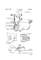
Fig. 1 illustrates a carburetor of the applicants improved type shown in side elevation with certain parts in cross section;
Fig. 2 is a top sectional view of the same construct-ion taken on the line 22 of Fig. 1.
Fig. 3 is a perspective view of the ring which causes the mixing of" the fuel and air and replaces the old Venturi tube.
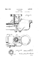
Fig. 4 illustrates a modified form; of the applicants invention being a side'elevational view with certain parts in cross section.
Fig. 5 shows a cross section of apart of this new construction taken on the line 55 of Fig. 4- and looking downward.
Fig. 6 is a bottom view of the modification" of the carburetor shown in Fig.- 4. a
Fig. 7 illustrates more or less diagrammatically a supercharger or blower attached to a carburetor of the type shown 'in Fig.4 so as to supply air under pressure'to the openings between the radial fins.
Fig. 8 is a side elevational vlewi-partlyin section showing a slightly modified form of the applicants carburetor which a collar forming a constriction abovethe ring takes the place of the tapered wallof the passage.
Fig. 9 is a top sectional view of theembodiinent of Fig. Sjtaken on line 9-9 of that embodiment shown in Fig. 8. a
' In the drawings the carburetor is composed oftwo'castings 1 and 2 whichhouse a suitable float mechanism in. a chamber 3 formed in casting 1. This float-mechanism isadapted to supply liquid fuel to the mixing device at a constant pressure. Being of'the conventional type the float chamberis not shown in detail. The castings land 2 further pro-' vide an air passage 4 comprising a horizontal passage and a vertical passage joining each other at right angles. Air'is adapted to enter at the end 5 of'the horizontal'passage and to flow therethrough into the vertical :pas-. sage and through the verticalpassage through exit 6 of the carburetor from which. it is led by a manifold to the internal combustion engine. Near the entrance end 5 of the pas-' sage 4 is located a conventional choke valve 7 which is adapted to-reduce or cut ofi? the supply of incoming air and near the exit 6 tom of the passage into close proximityto the point where the vertical passage begins are located a pair ofnozzles 15 and 16 connectedat their lower ends to the float chamher 3 and open at their upper ends so as to deliver fuel therefrom when the upper ends are subjected to a suction. At the lower end of the vertical part of passage 4 just above the point where it merges with the horizontal passage is located aring 18 which so directs n,
the air flow as to cause the propersuction upon the nozzles 15 and '16 and properImixing of the air and fuel passing through the pas sageway4.- The "ring 18 is in axial alignment with the vertical part of the passageway 4 which passageway is somewhat wider at the point 19 at which the ring is fixed and short constricted passageway 23 which widens at both ends and in which are located the ends of the nozzles 15 and 16. The passageway ring 18 is of smaller'diameter than the. section 19 oithe passage4in which it is located {and radially directed fins 24 and 25 extend from :the periphery of the body 22 to .the
' sage 19 to hold the {ring 18 in .position.-'lhe radial fins 24 and extend helically shout thenaxis of the ring so that the air which passes between them is given awhirling or Spinning motion..-
It will be noted thatthereare more of the radial fins on the side nearest; the inlet and T: this serves to balance theflow of air through is the areavthrough which the air may pass and hence the less is that side V Thebody 23 ofthe ring. 18 extends somewhat below the radial fins '24 and"25 thus forming a pocket 28 forthe retention of a supply of air under the radial fins. I
In Fig.4 the carburetor casting 1 is modified so that it provides a second inlet passage 31 for the air and the air entering through this passage is separated by the wall 32 from the air in passage 4. The wall 32 of the airpassage '31 extends upwardly from the bottom of the carburetor and surrounds the lower part of the body 22 .ofthe ring 18 thus supplying to the central opening in the ring 18 air taken into the carburetor through the passage 31 opening through the'bottom thereof at 34. Further construction maybe the air supplied from attach-ed to the carburetor for controlling the 'air taken in through the opening 34 but this can be supplied by anyone skilled in the art and hence has not been shown. This construction may consist of piping, valves and any other mechanism for supplying the desired quantity of a r 1n the proper condition to this part of the carburetor.
Fig. '7 shows a carburetor of the type illustrated-in Fig. 4 with an air pump oisuperch r rer v33 connected to one of the intakes of the carburetor so as to supply air under pressure'to the openings between the radial fins. The supercharger or air pumpis merely shown diagrammatically and may be of any of the conventional types, either the turbine vor pump type being common.
hen desired a'supercharger may be used with the carburetor as illustrated in Figs; 1 and 2 or a supercharger might be connected to the opening shown in Fig. 4.'
In the modification shown in the Figures 8, 9 and 10, the construction of the carburetor is slightly changed at the ring. The ring in this modification consists of a body portion 40 through which there is a short passage 41 which is narrow at a point near its upper end and tapers from this point towards either 34 of the carburetor as Lemme Iendh Radial fins 42 extend from thejbody 40 to the wall .of the passageway in which the 'ii g is located :andlugs 43 .on some of the fins seat in niches in :the wall to support the ring in place. The topsrofthe fins are tapered in th s embodiment so that they come to a point as they near the body of the ring. Thefins are not joined to the body of the ring all of the way tothe top but their inner edges are {rounded outward at 44 and the outer side of theitop part of the body 40 is rounded inward at 45.. This minimizes the breaking of the how .of air caused by the fins.
' The wholering is set somewhat lower in this embodiment and the body portion especially does not extend so far upward. Above the ring a collar 47 is located. This collar has an enlarged portion 48 which rests upon .the'tops of the fins-at their outer edges and is enclosed in the lower casting of the carburetor andaportion 49 of smaller diameter which extends upward into the upper carburetor casting. The passageway in the upper casting is straight and untapered in this embodiment. The collar 47 is rather short and has a large opening 50 therethrough which widens at both ends. Its effect is to direct the air from the openings between the fins towards thecenter of the passage and then permit a slight expansion of the gases to permit better mixing.
It will be noted that the lower part of the body 47 is somewhat longer in the embodias included in the appended claims are within the scope of this invention.
I claim: i
1. In a carburetor, the combination of means forming a main air passage and means forming a constriction therein comprising a ring of smaller diameter than said passage having a central passage therethrough and supported in said passage by radially extending fins there'being a greater number of fins on one side of the ring than on the otherand means in said central passage for supplying fuel to the air flowing therethrough. V y
2. In a carburetor, the combination of means forming a main air passage and means forming a constriction therein comprising a ring of smaller diameter than said passage having acentral passage therethrough and supported in: said passage by radially extending fins, the body of said ring extending beyond said fins in axial direction, there being a greater number of fins on one side of the ring than on the other and means in said central passage for supplying fuel to air flowing therethrough.
3. In a carburetor, the combination of means forming a main air passage and means forming a constriction therein comprising a ring of smaller diameter than said passage having a central passage therethrough and supported in said passage by radially extending fins there being a greater number" of fins on one side of the ring than on the other, means in said central passage for supplying fuel to the air flowing therethrough and means forming a separate passage for supplying a1r to said central passage.
4:. In a carburetor, the comblnatlon of means forming a main air passage and means forming a. constriction therein comprising a ring of smaller d1ameter than sald passage having a central passage therethrough and.
supported in said passage by radially extending fins there being a greater number of fins on one side of the ring than on the other,
means in said central passage for supplyingfuel to the air flowing therethrough, and means for forcing air into said carburetor.
5. In a carburetor the combination of means forming a main air passage, means forming a constriction therein having a central passage therethrough and a series of passages therethrough surrounding said central passage, said surrounding passages being, directly spirally around said central passage for giving the air passing-through a spiral movement, meansin said central passage for supplying fuel to the air flowing there through, means forming a separate passage for supplying air to said central passage and means for forcing air into said carburetor.
6. In a carburetor the combination of means forming a main air passage and means forming a constriction therein comprising a ring of smaller diameter than. said passage having a central passage therethrough and I supported in said passage by radially extending fins at least some of which are adaptedto engage notches in the wall of the main passage, said fins extending spirally about the axis of said ring, means in said central passage for supplying fuel to the air flowing therethrough, means forming a separate passage for supplying air to said central.
sage for supplying air to said centralpassage and means for forcing air into said main passage. g
8. In a carburetor the combination ofmeans forming a main air passage and means forming a constriction therein comprising a ring of smaller diameter than said passage having a central passage therethrough and supported in'said passageby radially extend ing fins at least someof which are adapted to engage notches in the wall of the main passage,*said fins extending spirally about the axis of said ring, means in said central passage for supplying fuel to the air flowing therethrough, means forming a separate passage for supplying air'to said'central passage and means for forcing air into said main passage. Y
9. In a carburetor the combination of a main. air passage, means in saidpassage forming. a constriction therein comprising a ring of smaller diameter than said passage,
having a central passage therethrough and supported in said passage by radially extending fins the tops of which are narrower towards the ring than towards the wall of the main passage and means for supplying fuel to air flowing through said constriction.
10. In a carburetor, the combination of a main air passage, means in said passage forming a constriction therein comprising av ring of smaller diameter thansaid passage, having a central passage therethrough and supported in said passage by radially extending fins the tops of which are narrower towards the ring than towards the wall of the main passage, the outside of'the top of the mug being rounded inwardly and the edges of the fins adjacent thereto being rounded outwardly to leave a groove between the said top and -fins,'a second constrictionin said main passage formed by a collar in said passage located immediately above said ringand fins, and means for supplying fuel to air passing through said first constriction.
In testimony whereof I afiix my signature. I
v lWILLIAM' M. THOMAS.
Priority Applications (1)
| Application Number | Priority Date | Filing Date | Title |
|---|---|---|---|
| US496541A US1857070A (en) | 1930-11-18 | 1930-11-18 | Carburetor |
Applications Claiming Priority (1)
| Application Number | Priority Date | Filing Date | Title |
|---|---|---|---|
| US496541A US1857070A (en) | 1930-11-18 | 1930-11-18 | Carburetor |
Publications (1)
| Publication Number | Publication Date |
|---|---|
| US1857070A true US1857070A (en) | 1932-05-03 |
Family
ID=23973084
Family Applications (1)
| Application Number | Title | Priority Date | Filing Date |
|---|---|---|---|
| US496541A Expired - Lifetime US1857070A (en) | 1930-11-18 | 1930-11-18 | Carburetor |
Country Status (1)
| Country | Link |
|---|---|
| US (1) | US1857070A (en) |
Cited By (12)
| Publication number | Priority date | Publication date | Assignee | Title |
|---|---|---|---|---|
| US2889214A (en) * | 1956-05-07 | 1959-06-02 | William J Linn | Liquid fuel atomizers |
| US3395899A (en) * | 1965-09-28 | 1968-08-06 | Univ California | Carburetor |
| US3653643A (en) * | 1970-04-03 | 1972-04-04 | Oliver M Tucker | Carburetor |
| US4015574A (en) * | 1974-11-18 | 1977-04-05 | Hanff Roy A | Apparatus for improving fuel-air mixture |
| US4276867A (en) * | 1979-03-19 | 1981-07-07 | Metzenthin Dieter W | Fuel atomizing device |
| WO1981002764A1 (en) * | 1980-03-21 | 1981-10-01 | W Sherlock | A device for improving the fuel/gas air mixture and the operation of an internal combustion engine |
| US4417562A (en) * | 1981-06-08 | 1983-11-29 | Dalke Arthur E | Carburetor mixture control apparatus |
| US4673536A (en) * | 1983-02-15 | 1987-06-16 | Morris George Q | Fuel admixture device |
| BE1009901A3 (en) * | 1995-12-28 | 1997-10-07 | Minta Boleslaw Antoni | Element for saving fuel in combustion engines and an inlet device fitted with the same |
| US6227185B1 (en) * | 1999-03-01 | 2001-05-08 | Edward J. Spracher | Air intake conduit fuel metering device |
| GB2410296A (en) * | 2003-11-10 | 2005-07-27 | Cho Jung Pin | Speed increaser for engine intake air |
| US20060156723A1 (en) * | 2004-12-30 | 2006-07-20 | C.R.F. Societa Consortile Per Azioni | Device for imparting a whirling motion on the flow of air for supplying a turbo-supercharged internal-combustion engine |
-
1930
- 1930-11-18 US US496541A patent/US1857070A/en not_active Expired - Lifetime
Cited By (15)
| Publication number | Priority date | Publication date | Assignee | Title |
|---|---|---|---|---|
| US2889214A (en) * | 1956-05-07 | 1959-06-02 | William J Linn | Liquid fuel atomizers |
| US3395899A (en) * | 1965-09-28 | 1968-08-06 | Univ California | Carburetor |
| US3653643A (en) * | 1970-04-03 | 1972-04-04 | Oliver M Tucker | Carburetor |
| US4015574A (en) * | 1974-11-18 | 1977-04-05 | Hanff Roy A | Apparatus for improving fuel-air mixture |
| US4276867A (en) * | 1979-03-19 | 1981-07-07 | Metzenthin Dieter W | Fuel atomizing device |
| WO1981002764A1 (en) * | 1980-03-21 | 1981-10-01 | W Sherlock | A device for improving the fuel/gas air mixture and the operation of an internal combustion engine |
| US4417562A (en) * | 1981-06-08 | 1983-11-29 | Dalke Arthur E | Carburetor mixture control apparatus |
| US4673536A (en) * | 1983-02-15 | 1987-06-16 | Morris George Q | Fuel admixture device |
| BE1009901A3 (en) * | 1995-12-28 | 1997-10-07 | Minta Boleslaw Antoni | Element for saving fuel in combustion engines and an inlet device fitted with the same |
| US6227185B1 (en) * | 1999-03-01 | 2001-05-08 | Edward J. Spracher | Air intake conduit fuel metering device |
| GB2410296A (en) * | 2003-11-10 | 2005-07-27 | Cho Jung Pin | Speed increaser for engine intake air |
| US20060156723A1 (en) * | 2004-12-30 | 2006-07-20 | C.R.F. Societa Consortile Per Azioni | Device for imparting a whirling motion on the flow of air for supplying a turbo-supercharged internal-combustion engine |
| US7322191B2 (en) * | 2004-12-30 | 2008-01-29 | C.R.F. Societa Consortile Per Azioni | Device for imparting a whirling motion on the flow of air for supplying a turbo-supercharged internal-combustion engine |
| US20080149207A1 (en) * | 2004-12-30 | 2008-06-26 | C.R.F. Societa Consortile Per Azioni | Device for imparting a whirling motion on the flow of air for supplying a turbo-supercharged internal-combustion engine |
| US7690200B2 (en) | 2004-12-30 | 2010-04-06 | C.R.F. Società Consortile Per Azioni | Device for imparting a whirling motion on the flow of air for supplying a turbo-supercharged internal-combustion engine |
Similar Documents
| Publication | Publication Date | Title |
|---|---|---|
| US1857070A (en) | Carburetor | |
| IL46868A (en) | Device for post-atomization of air-fuel mixture for internal combustion engines using a compressed mixture and an external ignition | |
| US1375898A (en) | Carbureter | |
| US1927090A (en) | Carburetor | |
| US2105056A (en) | Fuel-gas and air carburetor | |
| US1313521A (en) | Carbureter | |
| US1275032A (en) | Carbureter. | |
| US2349675A (en) | Charge forming system for internalcombustion engines with reuse of exhaust gases | |
| US1212478A (en) | Carbureter. | |
| US4207274A (en) | Carburetor | |
| US2011997A (en) | Carburetor | |
| US1551239A (en) | Carburetor | |
| US4180534A (en) | Apparatus for dispensing a fuel-air mixture in an airstream | |
| US1361529A (en) | Carbureter | |
| US1985712A (en) | Carburetor | |
| US1795685A (en) | Triple-atomization carburetor | |
| CS204969B2 (en) | Device for mixing the liquid fuel with the drawn in air | |
| US1141276A (en) | Carbureter. | |
| US1830588A (en) | Carburetor | |
| US1412000A (en) | Kerosene carburetor | |
| US2134021A (en) | Hydrocarbon vapor and air mixing device | |
| US3151190A (en) | Carburetor | |
| US1414035A (en) | Carburetor | |
| US1686413A (en) | Fuel-mixing and supercharging device | |
| US1370449A (en) | Carbureter |