EP1676056B1 - Differential axes of coordinates for a differential gear - Google Patents
Differential axes of coordinates for a differential gear Download PDFInfo
- Publication number
- EP1676056B1 EP1676056B1 EP04790549A EP04790549A EP1676056B1 EP 1676056 B1 EP1676056 B1 EP 1676056B1 EP 04790549 A EP04790549 A EP 04790549A EP 04790549 A EP04790549 A EP 04790549A EP 1676056 B1 EP1676056 B1 EP 1676056B1
- Authority
- EP
- European Patent Office
- Prior art keywords
- differential
- differential carrier
- diameter
- carrier according
- bearing arms
- Prior art date
- Legal status (The legal status is an assumption and is not a legal conclusion. Google has not performed a legal analysis and makes no representation as to the accuracy of the status listed.)
- Active
Links
- 230000007704 transition Effects 0.000 claims description 17
- 230000008878 coupling Effects 0.000 claims description 3
- 238000010168 coupling process Methods 0.000 claims description 3
- 238000005859 coupling reaction Methods 0.000 claims description 3
- 230000001050 lubricating effect Effects 0.000 claims 1
- 241000239290 Araneae Species 0.000 description 18
- 239000000314 lubricant Substances 0.000 description 10
- 238000005461 lubrication Methods 0.000 description 5
- 238000009826 distribution Methods 0.000 description 4
- 230000002349 favourable effect Effects 0.000 description 4
- 230000000694 effects Effects 0.000 description 3
- 238000005553 drilling Methods 0.000 description 2
- 238000003780 insertion Methods 0.000 description 2
- 230000037431 insertion Effects 0.000 description 2
- 238000000034 method Methods 0.000 description 2
- 238000010008 shearing Methods 0.000 description 2
- 238000003466 welding Methods 0.000 description 2
- 241000446313 Lamella Species 0.000 description 1
- 238000010276 construction Methods 0.000 description 1
- 238000005304 joining Methods 0.000 description 1
- 238000003860 storage Methods 0.000 description 1
Images


Classifications
-
- F—MECHANICAL ENGINEERING; LIGHTING; HEATING; WEAPONS; BLASTING
- F16—ENGINEERING ELEMENTS AND UNITS; GENERAL MEASURES FOR PRODUCING AND MAINTAINING EFFECTIVE FUNCTIONING OF MACHINES OR INSTALLATIONS; THERMAL INSULATION IN GENERAL
- F16H—GEARING
- F16H48/00—Differential gearings
- F16H48/20—Arrangements for suppressing or influencing the differential action, e.g. locking devices
- F16H48/27—Arrangements for suppressing or influencing the differential action, e.g. locking devices using internally-actuatable fluid pressure, e.g. internal pump types
-
- F—MECHANICAL ENGINEERING; LIGHTING; HEATING; WEAPONS; BLASTING
- F16—ENGINEERING ELEMENTS AND UNITS; GENERAL MEASURES FOR PRODUCING AND MAINTAINING EFFECTIVE FUNCTIONING OF MACHINES OR INSTALLATIONS; THERMAL INSULATION IN GENERAL
- F16H—GEARING
- F16H48/00—Differential gearings
- F16H48/06—Differential gearings with gears having orbital motion
- F16H48/08—Differential gearings with gears having orbital motion comprising bevel gears
-
- F—MECHANICAL ENGINEERING; LIGHTING; HEATING; WEAPONS; BLASTING
- F16—ENGINEERING ELEMENTS AND UNITS; GENERAL MEASURES FOR PRODUCING AND MAINTAINING EFFECTIVE FUNCTIONING OF MACHINES OR INSTALLATIONS; THERMAL INSULATION IN GENERAL
- F16H—GEARING
- F16H48/00—Differential gearings
- F16H48/20—Arrangements for suppressing or influencing the differential action, e.g. locking devices
- F16H48/22—Arrangements for suppressing or influencing the differential action, e.g. locking devices using friction clutches or brakes
-
- F—MECHANICAL ENGINEERING; LIGHTING; HEATING; WEAPONS; BLASTING
- F16—ENGINEERING ELEMENTS AND UNITS; GENERAL MEASURES FOR PRODUCING AND MAINTAINING EFFECTIVE FUNCTIONING OF MACHINES OR INSTALLATIONS; THERMAL INSULATION IN GENERAL
- F16H—GEARING
- F16H48/00—Differential gearings
- F16H48/06—Differential gearings with gears having orbital motion
- F16H48/08—Differential gearings with gears having orbital motion comprising bevel gears
- F16H2048/085—Differential gearings with gears having orbital motion comprising bevel gears characterised by shafts or gear carriers for orbital gears
-
- F—MECHANICAL ENGINEERING; LIGHTING; HEATING; WEAPONS; BLASTING
- F16—ENGINEERING ELEMENTS AND UNITS; GENERAL MEASURES FOR PRODUCING AND MAINTAINING EFFECTIVE FUNCTIONING OF MACHINES OR INSTALLATIONS; THERMAL INSULATION IN GENERAL
- F16H—GEARING
- F16H48/00—Differential gearings
- F16H48/38—Constructional details
- F16H2048/382—Methods for manufacturing differential gearings
-
- F—MECHANICAL ENGINEERING; LIGHTING; HEATING; WEAPONS; BLASTING
- F16—ENGINEERING ELEMENTS AND UNITS; GENERAL MEASURES FOR PRODUCING AND MAINTAINING EFFECTIVE FUNCTIONING OF MACHINES OR INSTALLATIONS; THERMAL INSULATION IN GENERAL
- F16H—GEARING
- F16H48/00—Differential gearings
- F16H48/20—Arrangements for suppressing or influencing the differential action, e.g. locking devices
- F16H48/26—Arrangements for suppressing or influencing the differential action, e.g. locking devices using fluid action, e.g. viscous clutches
Definitions
- the invention relates to a differential carrier for a differential gear, which is rotatably supported about its longitudinal axis A and driven in rotation, with two réellerädem, which are mounted coaxially to the longitudinal axis A in the differential carrier, and four differential gears on a spider with four radially to the longitudinal axis A in Differerttialkorb held bearing journals are rotatably arranged and are respectively in meshing engagement with the output wheels.
- Such a differential carrier for a differential gear is known from US Pat. No. 3,894,447 A, in which a journal cross is held with four bearing journals extending radially to the longitudinal axis.
- the spider includes a one-piece first pin with a central transverse opening into which a second pin is inserted.
- the second pin has a larger diameter portion on which a differential gear is to be stored and a subsequent smaller diameter portion which penetrates the transverse opening. On this smaller diameter portion of a pin sleeve is pushed, on which another balance wheel is mounted. Between the first and second sections, the second pin has a conical transition area.
- a differential gear which has a friction clutch for actuating, which is arranged in the differential carrier.
- the invention has for its object to propose a differential carrier of the type mentioned above, which offers an improved solution with a higher rigidity in the region of the spider of the differential cage.
- the solution consists in that two first opposing bearing journals of the journal cross are connected to each other and form at least one central transverse opening, and that two second bearing journals of the journal cross are designed separately from the first bearing journals and in each case a first section for insertion into the at least one transverse opening, a second portion for receiving the associated Aus stressessrads and a connecting the first and the second section transition portion having a continuously increasing in the direction of the second portion diameter.
- the first pin are integrally connected to each other, wherein on a continuous round rod substantially only the transverse bore to Recording the second pin must be performed.
- transverse bore between the two first pin and two countersinks can be provided in the connecting region of the two first pin, in which the two second pin are inserted with their inner ends only to the bottom of the countersink.
- the ratio of the first diameter d of the transverse opening to the second diameter of the bearing is between 0.4 and 0.6, the limit values being included. It is also particularly favorable for the second bearing journal when the ratio of the first diameter d to the second diameter D is between 0.4 and 0.6. This results in optimum strength of the web surrounding the transverse bore in relation to the inserted first portion of the second pin.
- the transitional portion of the inserted pin subsequent to the first portion has a first radius R1 with a ratio of 0.4 ⁇ R1 / D ⁇ 0.6, where D is the diameter of the second portion.
- the transition section has a second radius R2, whereby a ratio of 0.4 ⁇ R2 / D ⁇ 0.6 is also particularly favorable here.
- R1, R2 there is a conical lateral surface which forms an angle a with the pin axis which is smaller than an angle which is enclosed between an imaginary conical surface enveloping the transition section and the longitudinal axis.
- the pins are preferably used in continuous radial bores in the differential carrier, being supported to the outside with inserted into these radial bores circlips.
- the differential gears are preferably slidably mounted on the pin.
- the pins with longitudinal lubrication or lubrication pockets or circumferentially To provide lubrication, which extend beyond the bearing portion of the differential gears partially, so that lubricant can be supplied to the bearing.
- the cup-shaped differential carrier has a molded flange on the cup-shaped closed end of the differential carrier.
- the differential carrier is closed at the flange axially opposite end with a lid.
- a disk set is preferably arranged in the differential carrier between the arrangement of spider, differential gears and output wheels on the one hand and said cover on the other.
- the differential gear with a speed difference sensing actuator for example, in the manner of a shear pump, provided, this is preferably used between the disk pack and the lid.
- a differential carrier 11 which is to be stored rotatably in the housing of a differential gear.
- the storage takes place in particular on two sleeve lugs 12, 13, which are formed coaxially to the longitudinal axis A of the differential carrier.
- the differential cage consists of a pot-like first part 14 with an integrally formed thereon flange 16 and a lid 15 inserted into the first part 14.
- On the flange is a ring gear for rotating drive of the differential cage screwed.
- the first sleeve extension 12 is integrally connected to the first part 14 and the second sleeve extension 13 integrally connected to the lid 15.
- the lid 15 is held by means of a retaining ring 17 in abutment against a shoulder in the cup-shaped part 14.
- the locking ring 17 has an outwardly facing conical surface, so that the lid 15 is installed without play in the first part 14.
- the differential carrier 11 are arranged two coaxial with the longitudinal axis A arranged bevel gears 18, 19 and a number of four bevel gears with each lying radially to the longitudinal axis A axis of rotation, two of which (22, 23) can be seen in this figure.
- the four pinion gears are each arranged uniformly distributed in the meshing engagement with the two output bevel gears 18, 19 and over the circumference.
- the identifiable bevel gears 22, 23 each slide on second bearing pins 26, 27 which are inserted into radial bores 30, 31 in the first part 14 and held by retaining rings 32, 33 radially outward in this.
- the differential carrier 11 in the embodiment shown here belongs to a lockable differential gear and comprises a multi-plate clutch 41 and a shear pump assembly 51, as described for example in DE 196 19 891 C2 of the Applicant. Therefore, only the essential items are named.
- the multi-plate clutch 41 comprises a disk set 42 of first fins, which are rotatably connected to the housing part 14, and second fins, which are connected to a clutch hub 43.
- the disk set 42 is supported axially on a support disk 44 in the first part 14, when it is acted upon axially by an actuating piston 52 of the shear pump arrangement 51.
- the shear pump 51 further comprises a shearing blade 54 connected to a pump hub 53 and a shear groove and control element 55 which is rotatable relative to the cover part 15 which at the same time forms the pump housing.
- a pump chamber 60 is formed, in which the shearing blade 54 and the Schernut and control 55 eino.
- the cover part 15 is further formed from an annular space 56, an annular cover 57 and a plate spring 58 reservoir 61 can be seen, which is connected via holes, not shown, with the pump chamber 60 of the shear pump 51.
- the usernamekegelrad 18 has an internal toothing 34, in which a first side shaft can be inserted; the usernamekegelrad 19 has a second internal toothing 35, in which a second output shaft can be inserted.
- an internal toothing 45 of the coupling hub 43 and an internal toothing 59 of the pump hub 53 are formed.
- the clutch hub 43 and the pump hub 53 are rotatably connected to each other.
- a pressure is built up in the shear pump 51 at a speed difference between the output bevel gear 19 and the differential carrier 11, through which the piston 52 is displaced against the disk set 42, so that the toastkegelrad 19 is braked relative to the differential carrier 1.1.
- the piston 52 and the cover 15 are sealed by seals 62, 63 with respect to the pump hub 53.
- the mecanickegelrad 18 and the pump hub 53 are supported by sliding discs 36, 37 against the differential carrier 11 axially low friction.
- FIG. 3 the same details as in FIG. 2 are given the same numbers. The description is hereby incorporated by reference. Only the spider assembly is shown. With oblique lines are 27, 27 indicated on the pins 26, 27 lubricant grooves.
- lubricant grooves according to FIGS. 4 and 5 can also be exchanged mutatis mutandis, or all lubricant grooves can be designed in the same manner as in FIG. 4 or in the manner of the grooves shown in FIG. 5 in all bearing journals.
- FIG. 6 shows a second embodiment of an arrangement of differential bevel wheels 20, 21, 22 and bearing journals 24, 25, 26 as a subassembly in a view in the direction of the longitudinal axis A.
- the arrangement of Figure 6 differs only in that only three pins 24, 25, 26 are provided.
- the two first pins 24, 25 are integrally formed and have the transverse bore 38, in which the second pin 26 is inserted with its first portion 28.
- This embodiment is less expensive to produce because it can be dispensed with a bearing pin with associated differential. Imbalance can be compensated by a corresponding mass distribution in the differential carrier not shown here.
- FIG. 7 the same details as in FIG. 6 are given the same numbers. The description is hereby incorporated by reference. Only the spider assembly is shown. With an oblique line, a lubricant groove 68 is indicated on the pin 26.
- Figure 8 shows the inner end of a second pin 26, 27 according to one of the aforementioned embodiments.
- the second pin 26 has a first portion 28 of reduced diameter d for insertion into the transverse bore 38 of the first pin 24, not shown here, 25, a second portion 39 having a larger diameter D for supporting an associated Aus stressessrads 22 and a Having the first and the second portion 28, 39 connecting transition portion 46 which has a steadily increasing toward the second portion 39 diameter.
- the diameter d of the first portion 28 corresponds approximately to the diameter of the transverse bore 38, wherein between the pin and bore a clearance fit is formed.
- the ratio of the first Diameter d of the first portion 28 to the second diameter D of the second portion 39 is between 0.4 and 0.6, ie, 0.4 ⁇ d / D ⁇ 0.6. This ratio results in an optimum rigidity of the inserted pin 26 in relation to the rigidity of the pin 24, 25 with transverse bore 38. It is further apparent that the transition portion 46 adjacent to the first portion 28 has a first radius R1 and adjacent to the second portion 39th has a second radius R2.
- the radii R1 and R2 are chosen to be particularly large, so that the notch effect is minimized and a uniform stress distribution is achieved.
- the ratio of the first radius R1 to the diameter D of the second portion 39 is therefore between 0.4 and 0.6, with the limit values included, ie 0.4 ⁇ R1 / D ⁇ 0.6. Also for the ratio between the second radius R2 and the diameter D is 0.4 ⁇ R2 / D ⁇ 0.6 for an optimum voltage curve between the transition portion 46 and the second portion 39.
- the angle a, between a conical lateral surface of the transition section 46 and the pin axis is smaller than an angle enclosed between an imaginary conical surface 48 enveloping the transition section 46 and the pin axis. That means, a ⁇ arctan 0 . 5 ⁇ D - d / L . where L is the length of the transition section 46. This course also results in a particularly high strength and a good stress distribution.
Landscapes
- Engineering & Computer Science (AREA)
- General Engineering & Computer Science (AREA)
- Mechanical Engineering (AREA)
- Physics & Mathematics (AREA)
- Fluid Mechanics (AREA)
- Retarders (AREA)
- Length Measuring Devices By Optical Means (AREA)
Abstract
Description
Die Erfindung betrifft einen Differentialkorb für ein Differentialgetriebe, der um seine Längsachse A drehbar gelagert und drehend antreibbar ist, mit zwei Ausgangsrädem, die koaxial zur Längsachse A im Differentialkorb gelagert sind, und vier Ausgleichsrädern, die auf einem Zapfenkreuz mit vier radial zur Längsachse A im Differerttialkorb gehaltenen Lagerzapfen drehbar angeordnet sind und jeweils mit den Ausgangsrädern im Verzahnungseingriff sind.The invention relates to a differential carrier for a differential gear, which is rotatably supported about its longitudinal axis A and driven in rotation, with two Ausgangsrädem, which are mounted coaxially to the longitudinal axis A in the differential carrier, and four differential gears on a spider with four radially to the longitudinal axis A in Differerttialkorb held bearing journals are rotatably arranged and are respectively in meshing engagement with the output wheels.
Aus der US 3 894 447 A ist ein solcher Differentialkorb für ein Differentialgetriebe bekannt, in dem ein Zapfenkreuz mit vier radial zur Längsachse verlaufenden Lagerzapfen gehalten ist. Das Zapfenkreuz umfaßt einen einstückigen ersten Zapfen mit einer zentralen Queröffnung, in die ein zweiter Zapfen eingesteckt ist. Der zweite Zapfen hat einen Abschnitt größeren Durchmessers, auf dem ein Ausgleichsrad zu lagern ist und einen hieran anschließenden Abschnitt kleineren Durchmessers, der die Queröffnung durchdringt. Auf diesen Abschnitt kleineren Durchmessers ist eine Zapfenhülse aufgeschoben, auf der ein weiteres Ausgleichsrad gelagert ist. Zwischen dem ersten und dem zweiten Abschnitt hat der zweite Zapfen einen konischen übergangsbereich.Such a differential carrier for a differential gear is known from US Pat. No. 3,894,447 A, in which a journal cross is held with four bearing journals extending radially to the longitudinal axis. The spider includes a one-piece first pin with a central transverse opening into which a second pin is inserted. The second pin has a larger diameter portion on which a differential gear is to be stored and a subsequent smaller diameter portion which penetrates the transverse opening. On this smaller diameter portion of a pin sleeve is pushed, on which another balance wheel is mounted. Between the first and second sections, the second pin has a conical transition area.
Ein weiterer Differentialkorb ist aus der DE 199 19 515 C2 bekannt. Hier werden vier zugekeilte Lagerzapfen für vier Ausgleichskegelräder mittig zu einem Zapfenkreuz verschweißt. Nachteilig ist hierbei, daß die Zapfen hierfür in eine geeignete Vorrichtung eingespannt werden müssen und nach dem Verschweißen des Zapfenkreuzes die Zapfen gerichtet werden müssen- Die Kosten für den Schweißvorgang mit den genannten Einricht- und Richtvorgängen sind nachteilig hoch.Another differential carrier is known from DE 199 19 515 C2. Here, four wedged bearing journals for four bevel gears are welded in the middle to form a spider. The disadvantage here is that the pins must be clamped for this purpose in a suitable device and after the welding of the spider, the pins must be addressed- The cost of the welding process with said setup and straightening processes are disadvantageously high.
Aus der gattungsgemäßen EP 0 864 779 A1 ist ein Differentialgetriebe mit vier Lagerzapfen für vier Ausgleichskegelräder bekannt. Dabei sind zwei der Lagerzapfen einstückig gestaltet und weisen eine Querbohrung auf. In die Querbohrung sind die beiden senkrecht zum einstückigen Lagerzapfen verlaufenden Lagerzapfen jeweils mit einem inneren ersten Abschnitt eingesteckt. Der Übergang vom eingesteckten ersten Abschnitt zum das Ausgleichsrad tragenden zweiten Abschnitt ist sprunghaft, so daß es hier zu Kerbwirkung kommen kann.From the generic EP 0 864 779 A1 a differential gear with four journals for four bevel gears is known. Two of the journals are designed in one piece and have a transverse bore. In the transverse bore, the two perpendicular to the one-piece bearing journal bearing journals are each inserted with an inner first portion. The transition from the inserted first section to the second wheel bearing the balance wheel is abrupt, so that it can come to notch effect here.
Aus der DE 36 34 394 A1 ist ein ähnliches Differentialgetriebe mit vier Lagerzapfen für vier Ausgleichskegelräder bekannt. Dabei weisen die Lagerzapfen über den Umfang verteilte Schmiernuten zum gleitenden Lagern der Ausgleichsräder auf den Lagerzapfen auf. Die Lagerzapfen sind in Radialbohrungen im Differentialkorb aufgenommen und durch einen um den Differentialkorb umlaufenden Sicherungsring gehalten.From
Aus der DE 44 24 202 C1 ist ein Differentialgetriebe bekannt, das zur Betätigung eine Reibungskupplung aufweist, die in dem Differentialkorb angeordnet ist.From DE 44 24 202 C1, a differential gear is known, which has a friction clutch for actuating, which is arranged in the differential carrier.
Der Erfindung liegt die Aufgabe zugrunde, einen Differentialkorb der eingangs genannten Art vorzuschlagen, der im Bereich des Zapfenkreuzes des Differentialkorbes eine verbesserte Lösung mit einer höheren Steifigkeit bietet.The invention has for its object to propose a differential carrier of the type mentioned above, which offers an improved solution with a higher rigidity in the region of the spider of the differential cage.
Die Lösung besteht darin, daß zwei erste einander gegenüberliegende Lagerzapfen des Zapfenkreuzes miteinander verbunden sind und zumindest eine zentrale Queröffnung bilden, und daß zwei zweite Lagerzapfen des Zapfenkreuzes getrennt von den ersten Lagerzapfen ausgeführt sind und jeweils einen ersten Abschnitt zum Einstecken in die zumindest eine Queröffnung, einen zweiten Abschnitt zur Aufnahme des zugehörigen Ausgleichsrads sowie einen den ersten und den zweiten Abschnitt verbindenden Übergangsabschnitt mit einem in Richtung zum zweiten Abschnitt stetig zunehmenden Durchmesser aufweisen. Hiermit ist die Möglichkeit gegeben, die Anzahl der Zapfenteile auf zwei zu reduzieren und das Zapfenkreuz nach Art einer Steckverbindung im Differentialkorb zusammenzusetzen. Aufgrund des Zusammenfügens erst im Differentialkorb ergibt sich eine verbesserte Montagemöglichkeit der Ausgleichsräder auf den Zapfen, die es zuläßt, einen zumindest einseitig topfartig geschlossenen Differentialkorb zu verwenden, der auf Montageöffnungen für die Ausgleichsräder am Umfang verzichtet. In dem Fall, daß zwei erste und lediglich ein zweiter Lagerzapfen verwendet werden, können auftretende Unwuchten durch entsprechende Ausgleichsmassen am Differentialkorb ausgeglichen werden. Eine symmetrische Zapfenkreuzanordnung ergibt sich bei Verwendung von insgesamt vier Lagerzapfen, wobei zwei zweite Lagerzapfen in zwei erste Lagerzapfen eingesteckt sind.The solution consists in that two first opposing bearing journals of the journal cross are connected to each other and form at least one central transverse opening, and that two second bearing journals of the journal cross are designed separately from the first bearing journals and in each case a first section for insertion into the at least one transverse opening, a second portion for receiving the associated Ausgleichsrads and a connecting the first and the second section transition portion having a continuously increasing in the direction of the second portion diameter. This makes it possible to reduce the number of spigot parts to two and to assemble the spider in the manner of a connector in the differential carrier. Due to the joining only in the differential carrier results in an improved mounting possibility of the differential gears on the pin, which allows to use an at least one side pot-shaped closed differential carrier, which dispenses with mounting holes for the differential gears on the circumference. In the event that two first and only a second journals are used, occurring imbalances can be compensated by appropriate balancing weights on the differential carrier. A symmetrical spider assembly results when using a total of four journals, with two second journals are inserted in two first journals.
In bevorzugter Ausführung sind die ersten Zapfen einstückig miteinander verbunden, wobei an einem durchgehenden Rundstab im wesentlichen nur die Querbohrung zur Aufnahme der zweiten Zapfen ausgeführt werden muß. Grundsätzlich wäre es auch möglich, zwei Einzelzapfen mit Halbzylinderausnehmungen an ihren Enden unter Bildung einer inneren Queröffnung zu verschweißen.In a preferred embodiment, the first pin are integrally connected to each other, wherein on a continuous round rod substantially only the transverse bore to Recording the second pin must be performed. In principle, it would also be possible to weld two individual pins with Halbzylinderausnehmungen at their ends to form an inner transverse opening.
Anstelle der Querbohrung zwischen den beiden ersten Zapfen können auch zwei Ansenkungen im Verbindungsbereich der beiden ersten Zapfen vorgesehen sein, in die die beiden zweiten Zapfen mit ihren inneren Enden jeweils nur bis zum Boden der Ansenkung eingesteckt werden.Instead of the transverse bore between the two first pin and two countersinks can be provided in the connecting region of the two first pin, in which the two second pin are inserted with their inner ends only to the bottom of the countersink.
Bei den ersten Lagerzapfen liegt das Verhältnis des ersten Durchmessers d der Queröffnung zum zweiten Durchmesser der Lagerstelle zwischen 0,4 und 0,6, wobei die Grenzwerte mit eingeschlossen sein sollen. Auch für die zweiten Lagerzapfen ist es besonders günstig, wenn das Verhältnis des ersten Durchmessers d zum zweiten Durchmesser D zwischen 0,4 und 0,6 liegt. So ergibt sich eine optimale Festigkeit der die Querbohrung umgebenden Stege im Verhältnis zum eingesteckten ersten Abschnitt des zweiten Zapfens.In the case of the first bearing journals, the ratio of the first diameter d of the transverse opening to the second diameter of the bearing is between 0.4 and 0.6, the limit values being included. It is also particularly favorable for the second bearing journal when the ratio of the first diameter d to the second diameter D is between 0.4 and 0.6. This results in optimum strength of the web surrounding the transverse bore in relation to the inserted first portion of the second pin.
Vorzugsweise hat der Übergangsabschnitt des eingesteckten Zapfens im Anschluß an den ersten Abschnitt einen ersten Radius R1 mit einem Verhältnis 0,4 ≤ R1/D ≤ 0,6 auf, wobei D der Durchmesser des zweiten Abschnitts ist. Im Anschluß an den zweiten Abschnitt weist der Übergangsabschnitt einen zweiten Radius R2 auf, wobei auch hier ein Verhältnis von 0,4 ≤ R2/D ≤ 0,6 besonders günstig ist. Zwischen den beiden Radien R1, R2 befindet sich eine konische Mantelfläche, die mit der Zapfenachse einen Winkel a einschließt, der kleiner ist als ein Winkel, der zwischen einer den Übergangsabschnitt einhüllenden gedachten Kegelfläche und der Längsachse eingeschlossenen ist. Durch diese Maßnahmen wird die Kerbwirkung in den zweiten Lagerzapfen minimiert und eine besonders günstige Spannungsverteilung erreicht.Preferably, the transitional portion of the inserted pin subsequent to the first portion has a first radius R1 with a ratio of 0.4 ≤ R1 / D ≤ 0.6, where D is the diameter of the second portion. Subsequent to the second section, the transition section has a second radius R2, whereby a ratio of 0.4 ≦ R2 / D ≦ 0.6 is also particularly favorable here. Between the two radii R1, R2 there is a conical lateral surface which forms an angle a with the pin axis which is smaller than an angle which is enclosed between an imaginary conical surface enveloping the transition section and the longitudinal axis. By these measures, the notch effect is minimized in the second journals and achieved a particularly favorable stress distribution.
Die Zapfen werden bevorzugt in durchgehende Radialbohrungen im Differentialkorb eingesetzt, wobei sie nach außen mit in diese Radialbohrungen eingesetzte Sicherungsringen abgestützt werden. Die Ausgleichsräder sind vorzugsweise gleitend auf den Zapfen gelagert. Zur Verbesserung der Schmierung ist hierbei vorgesehen, die Zapfen mit längsverlaufenden Schmiernuten oder Schmiertaschen oder umfangsverlaufenden Schmiernuten zu versehen, die teilweise über den Lagerbereich der Ausgleichsräder hinausreichen, so daß Schmiermittel der Lagerstelle zugeführt werden kann.The pins are preferably used in continuous radial bores in the differential carrier, being supported to the outside with inserted into these radial bores circlips. The differential gears are preferably slidably mounted on the pin. To improve the lubrication is provided here, the pins with longitudinal lubrication or lubrication pockets or circumferentially To provide lubrication, which extend beyond the bearing portion of the differential gears partially, so that lubricant can be supplied to the bearing.
In günstiger Ausführung ist vorgesehen, daß der topfartig ausgebildete Differentialkorb einen angeformten Flansch an dem topfartig geschlossenen Ende des Differentialkorbs hat. Dabei wird der Differentialkorb an dem dem Flansch axial entgegenliegenden Ende mit einem Deckel verschlossen. Soweit vorgesehen ist, ein Differentialgetriebe als sperrbares Differentialgetriebe auszubilden, wird im Differentialkorb ein Lamellenpaket vorzugsweise zwischen der Anordnung aus Zapfenkreuz, Ausgleichsrädern und Ausgangsrädern einerseits und dem genannten Deckel andererseits angeordnet. Soweit das Differentialgetriebe mit einer drehzahldifferenzfühlenden Betätigungsvorrichtung, beispielweise nach Art einer Scherpumpe, versehen ist, wird diese bevorzugt zwischen dem Lamellenpaket und dem Deckel eingesetzt.In a favorable embodiment, it is provided that the cup-shaped differential carrier has a molded flange on the cup-shaped closed end of the differential carrier. In this case, the differential carrier is closed at the flange axially opposite end with a lid. As far as it is intended to form a differential gear as a lockable differential gear, a disk set is preferably arranged in the differential carrier between the arrangement of spider, differential gears and output wheels on the one hand and said cover on the other. As far as the differential gear with a speed difference sensing actuator, for example, in the manner of a shear pump, provided, this is preferably used between the disk pack and the lid.
Ungeachtet der Tatsache, daß bevorzugt Ausgleichskegelräder und Ausgangskegelräder vorgeschlagen werden und dargestellt sind, ist es auch möglich, die Ausgleichsräder als Stirnräder und die Ausgangsräder als Kronenräder auszuführen.Notwithstanding the fact that preferably bevel bevel gears and output bevel gears are proposed and illustrated, it is also possible to perform the differential gears as spur gears and the output wheels as crown wheels.
Ein bevorzugtes Ausführungsbeispiel der Erfindung ist in den Zeichnungen dargestellt und wird nachstehend beschrieben.
- Figur 1
- zeigt einen Differentialkorb mit einem erfindungsgemäßen Zapfenkreuz im Längsschnitt;
- Figur 2
- zeigt das Zapfenkreuz nach Figur 1 mit aufgesetzten Ausgleichsrädern im Querschnitt;
- Figur 3
- zeigt das Zapfenkreuz nach Figur 2 als Einzelheit;
- Figur 4
- zeigt die beiden ersten Zapfen des erfindungsgemäßen Zapfenkreuzes nach Figur 3;
- Figur 5
- zeigt einen der beiden zweiten Zapfen des erfindungsgemäßen Zapfenkreuzes nach Figur 3 als Einzelheit in zwei Ansichten;
- Figur 6
- zeigt ein Zapfenkreuz nach einer zweiten Ausführungsform mit aufgesetzten Ausgleichsrädern im Querschnitt;
- Figur 7
- zeigt das Zapfenkreuz nach Figur 6 als Einzelheit;
- Figur 8
- zeigt einen der beiden zweiten Lagerzapfen eines erfindungsgemäßen Zapfenkreuzes nach einer der vorstehenden Figuren im Detail.
- FIG. 1
- shows a differential carrier with a spider according to the invention in longitudinal section;
- FIG. 2
- shows the spider of Figure 1 with patch wheels in cross-section;
- FIG. 3
- shows the spider of Figure 2 as a detail;
- FIG. 4
- shows the two first pin of the spider of the invention according to Figure 3;
- FIG. 5
- shows one of the two second pin of the spider of the invention according to Figure 3 as a detail in two views;
- FIG. 6
- shows a spider according to a second embodiment with mounted differential gears in cross section;
- FIG. 7
- shows the spider of Figure 6 as a detail;
- FIG. 8
- shows one of the two second journal of a spider according to the invention according to one of the preceding figures in detail.
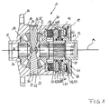
In Figur 1 ist ein Differentialkorb 11 gezeigt, der im Gehäuse eines Differentialgetriebes drehbar zu lagern ist. Hierbei findet die Lagerung insbesondere auf zwei Hülsenansätzen 12, 13 statt, die koaxial zur Längsachse A des Differentialkorbs ausgebildet sind. Der Differentialkorb besteht aus einem topfartigen ersten Teil 14 mit einem daran einstückig angeformten Flansch 16 sowie einem in das erste Teil 14 eingesetzten Deckel 15. Am Flansch ist ein Tellerrad zum drehenden Antrieb des Differentialkorbes anschraubbar. Der erste Hülsenansatz 12 ist einstückig mit dem ersten Teil 14 und der zweite Hülsenansatz 13 einstückig mit dem Deckel 15 verbunden. Der Dekkel 15 ist mittels eines Sicherungsringes 17 in Anlage gegen einen Absatz im topfartigen Teil 14 gehalten. Der Sicherungsring 17 hat eine nach außen weisende Konusfläche, so daß der Deckel 15 spielfrei im ersten Teil 14 verbaut ist. Im Differentialkorb 11 sind zwei koaxial zur Längsachse A angeordnete Ausgleichskegelräder 18, 19 sowie eine Anzahl von vier Ausgleichskegelrädern mit jeweils radial zur Längsachse A liegender Drehachse angeordnet, von denen zwei (22, 23) in dieser Figur zu erkennen sind. Die vier Ausgleichskegelräder sind jeweils im Verzahnungseingriff mit den beiden Ausgangskegelrädern 18, 19 und über dem Umfang gleichmäßig verteilt angeordnet. Die erkennbaren Ausgleichskegelräder 22, 23 laufen jeweils gleitend auf zweiten Lagerzapfen 26, 27, die in radiale Bohrungen 30, 31 im ersten Teil 14 eingesteckt sind und mittels Sicherungsringen 32, 33 nach radial außen in diesen gehalten sind. Mit ihren im Durchmesser reduzierten inneren Enden 28, 29 stützen sich die zweiten Lagerzapfen 26, 27 unmittelbar aneinander ab. Hierbei werden diese Zapfen durch ein erstes Paar Lagerzapfen 24, 25, das erst später erläutert werden kann, seitlich abgestützt und relativ zueinander gehalten. Der Differentialkorb 11 in der hier dargestellten Ausgestaltung gehört zu einem sperrbaren Differentialgetriebe und umfaßt eine Lamellenkupplung 41 und eine Scherpumpenanordnung 51, wie sie beispielsweise in der DE 196 19 891 C2 der Anmelderin beschrieben sind. Es werden daher nur die wesentlichen Einzelteile benannt. Die Lamellenkupplung 41 umfaßt ein Lamellenpaket 42 aus ersten Lamellen, die mit dem Gehäuseteil 14 drehfest verbunden sind, und zweiten Lamellen, die mit einer Kupplungsnabe 43 verbunden sind. Das Lamellenpaket 42 stützt sich an einer Stützscheibe 44 im ersten Teil 14 axial ab, wenn es von einem Stellkolben 52 der Scherpumpenanordnung 51 axial beaufschlagt wird. Die Scherpumpe 51 umfaßt weiter eine mit einer Pumpennabe 53 verbundene Scherlamelle 54 sowie ein gegenüber dem Deckelteil 15, das zugleich das Pumpengehäuse bildet, begrenzt verdrehbares Schernut- und Steuerelement 55. Im Deckelteil 15 ist ein Pumpenraum 60 gebildet, in dem die Scherlamelle 54 und das Schernut- und Steuerelement 55 einliegen. Im Deckelteil 15 ist weiterhin ein aus einem Ringraum 56, einem Ringdeckel 57 und einer Tellerfeder 58 gebildetes Reservoir 61 erkennbar, das über nicht dargestellte Bohrungen mit dem Pumpenraum 60 der Scherpumpe 51 verbunden ist. Das Ausgangskegelrad 18 hat eine Innenverzahnung 34, in die eine erste Seitenwelle eingesteckt werden kann; das Ausgangskegelrad 19 hat eine zweite Innenverzahnung 35, in die eine zweite Ausgangswelle eingesteckt werden kann. Übereinstimmend mit der Innenverzahnung 35 ist eine Innenverzahnung 45 der Kupplungsnabe 43 und eine Innenverzahnung 59 der Pumpennabe 53 ausgebildet. Durch Einstecken einer zweiten Seitenwelle werden hierdurch das Ausgangskegelrad 19, die Kupplungsnabe 43 und die Pumpennabe 53 drehfest miteinander verbunden. Als Folge hiervon wird bei einer Drehzahldifferenz zwischen dem Ausgangskegelrad 19 und dem Differentialkorb 11 ein Druck in der Scherpumpe 51 aufgebaut, durch den der Kolben 52 gegen das Lamellenpaket 42 verschoben wird, so daß das Ausgangskegelrad 19 gegenüber dem Differentialkorb 1.1 abgebremst wird. Der Kolben 52 und der Deckel 15 sind durch Dichtungen 62, 63 gegenüber der Pumpennabe 53 abgedichtet. Das Ausgangskegelrad 18 und die Pumpennabe 53 sind über Gleitscheiben 36, 37 gegenüber dem Differentialkorb 11 axial reibungsarm abgestützt.In Figure 1, a differential carrier 11 is shown, which is to be stored rotatably in the housing of a differential gear. Here, the storage takes place in particular on two sleeve lugs 12, 13, which are formed coaxially to the longitudinal axis A of the differential carrier. The differential cage consists of a pot-like
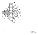
In Figur 2 ist die Anordnung aus Ausgleichskegelrädern 20, 21, 22, 23 und Lagerzapfen 24, 25, 26, 27 als Unterbaugruppe in Ansicht in Richtung der Längsachse A gezeigt, die hier nicht dargestellt ist. Hierbei ist erkennbar, daß die ersten Zapfen 24, 25 einstückig ausgebildet sind und eine Querbohrung 38 haben, in die die zweiten Zapfen 26, 27 mit inneren ersten Abschnitten 28, 29 im wesentlichen spielfrei einsteckbar sind, so daß sie quer zu ihrer Längserstreckung gesichert sind. Weiterhin ist erkennbar, daß die zweiten Zapfen 26, 27 unabhängig voneinander ausgeführt sind und mit ihren inneren ersten Abschnitten 28, 29 flächig aneinanderstoßen. Aus der Bauweise des in Figur 1 gezeigten Differentialkorbs 11 und der hier gezeigten Anordnung der Lagerzapfen und Ausgleichsräder ergibt sich, daß die Ausgleichsräder 20, 21, 22, 23 bei noch nicht montiertem Deckel 15 in das erste Gehäuseteil 14 eingeführt werden können, das dann zunächst die einheitliche Zapfenanordnung 24, 25 quer in den Differentialkorb 11 eingeführt wird, wobei die Ausgleichskegelräder 20, 21 auf ihre Lagerzapfen aufgefädelt werden und daß schließlich die Zapfen 25, 26 radial in den Differentialkorb eingesteckt werden, wobei die Ausgleichskegelräder 22, 23 auf ihre Lagerzapfen aufgefädelt werden und diese in die Querbohrung 38 bis zum gegenseitigen Anschlag eingesteckt werden. Danach können die Lagerzapfen 24, 25, 26, 27 durch Sicherungsringe im Differentialkorb gesichert werden.In Figure 2, the arrangement of
In Figur 3 sind gleiche Einzelheiten wie in Figur 2 mit gleichen Ziffern belegt. Auf die Beschreibung wird insoweit Bezug genommen. Es ist ausschließlich die Zapfenkreuzanordnung gezeigt. Mit schrägen Linien sind an den Zapfen 26, 27 Schmiermittelnuten 68, 69 angedeutet.In FIG. 3, the same details as in FIG. 2 are given the same numbers. The description is hereby incorporated by reference. Only the spider assembly is shown. With oblique lines are 27, 27 indicated on the
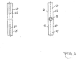
In Figur 4 ist das einstückig ausgebildete Zapfenpaar 24, 25 mit der Querbohrung 38 als Einzelheit dargestellt. Es ist weiterhin im Bereich der Ausgleichsräderlagerung jeweils ein Paar von Abflachungen 64, 65, 66, 67 an den Zapfen erkennbar, das der Schmiermittelzuführung im Bereich der Lagerung der Ausgleichsräder dient.In Figure 4, the integrally formed
In Figur 5 ist einer der Lagerzapfen 26, 27 als Einzelheit in zwei Seitenansichten erkennbar, wobei zum einen die Durchmesserreduzierung an den inneren Enden 28, 29 und zum anderen die als schräge Umfangsnut ausgeführte Schmiermittelnut 68, 69 erkennbar ist, die ebenfalls der Schmiermittelzuführung unter die Ausgleichsräder dient.In Figure 5, one of the bearing pins 26, 27 recognizable as a detail in two side views, on the one hand, the diameter reduction at the inner ends 28, 29 and the other as the oblique circumferential groove running
Die Art der Schmiermittelnuten nach den Figuren 4 und 5 kann auch sinngemäß vertauscht werden oder sämtliche Schmiermittelnuten können übereinstimmend nach Art der in Figur 4 oder nach Art der in Figur 5 gezeigten Nuten in allen Lagerzapfen ausgeführt werden.The type of lubricant grooves according to FIGS. 4 and 5 can also be exchanged mutatis mutandis, or all lubricant grooves can be designed in the same manner as in FIG. 4 or in the manner of the grooves shown in FIG. 5 in all bearing journals.
In Figur 6 ist eine zweite Ausführungsform einer Anordnung aus Ausgleichskegelrädern 20, 21, 22 und Lagerzapfen 24, 25, 26 als Unterbaugruppe in Ansicht in Richtung der Längsachse A gezeigt. Dabei sind gleiche Einzelheiten mit gleichen Ziffern wie in Figur 2 belegt, auf deren Beschreibung insoweit Bezug genommen wird. Die Anordnung nach Figur 6 unterscheidet sich lediglich dadurch, daß nur drei Zapfen 24, 25, 26 vorgesehen sind. Dabei sind die zwei ersten Zapfen 24, 25 einstückig gestaltet und weisen die Querbohrung 38 auf, in die der zweite Zapfen 26 mit seinem ersten Abschnitt 28 eingesteckt ist. Diese Ausführungsform ist kostengünstiger herstellbar, da auf einen Lagerzapfen mit zugehörigem Ausgleichsrad verzichtet werden kann. Unwuchten können durch eine entsprechende Masseverteilung im hier nicht dargestellten Differentialkorb ausgeglichen werden.FIG. 6 shows a second embodiment of an arrangement of
In Figur 7 sind gleiche Einzelheiten wie in Figur 6 mit gleichen Ziffern belegt. Auf die Beschreibung wird insoweit Bezug genommen. Es ist ausschließlich die Zapfenkreuzanordnung gezeigt. Mit einer schrägen Linie ist an dem Zapfen 26 eine Schmiermittelnut 68 angedeutet.In FIG. 7, the same details as in FIG. 6 are given the same numbers. The description is hereby incorporated by reference. Only the spider assembly is shown. With an oblique line, a
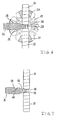
Figur 8 zeigt das innere Ende eines zweiten Zapfens 26, 27 nach einer der vorgenannten Ausführungsformen. Es ist ersichtlich, daß der zweite Zapfen 26 einen ersten Abschnitt 28 mit reduziertem Durchmesser d zum Einstecken in die Querbohrung 38 des hier nicht dargestellten ersten Zapfens 24, 25, einen zweiten Abschnitt 39 mit einem größeren Durchmesser D zum Lagern eines zugehörigen Ausgleichsrads 22 sowie einen den ersten und den zweiten Abschnitt 28, 39 verbindenden Übergangsabschnitt 46 aufweist, der einen in Richtung zum zweiten Abschnitt 39 stetig zunehmenden Durchmesser hat. Der Durchmesser d des ersten Abschnitts 28 entspricht dabei etwa dem Durchmesser der Querbohrung 38, wobei zwischen Zapfen und Bohrung eine Spielpassung ausgebildet ist. Das Verhältnis des ersten Durchmessers d des ersten Abschnitts 28 zum zweiten Durchmesser D des zweiten Abschnitts 39 liegt zwischen 0,4 und 0,6, d.h. 0,4 ≤ d/D ≤ 0,6. Durch dieses Verhältnis ergibt sich eine optimale Steifigkeit des eingesteckten Zapfens 26 im Verhältnis zur Steifigkeit des Zapfens 24, 25 mit Querbohrung 38. Es ist weiterhin ersichtlich, daß der Übergangsabschnitt 46 benachbart zum ersten Abschnitt 28 einen ersten Radius R1 aufweist und benachbart zum zweiten Abschnitt 39 einen zweiten Radius R2 aufweist. Die Radien R1 und R2 sind besonders groß gewählt, so daß die Kerbwirkung minimiert und eine gleichmäßige Spannungsverteilung erreicht wird. Das Verhältnis des ersten Radius R1 zum Durchmesser D des zweiten Abschnitts 39 liegt daher zwischen 0,4 und 0,6, wobei die Grenzwerte mit eingeschlossen sind, d.h. 0,4 ≤ R1/D ≤ 0,6. Auch für das Verhältnis zwischen dem zweiten Radius R2 und dem Durchmesser D gilt 0,4 ≤ R2/D ≤ 0,6 für einen optimalen Spannungsverlauf zwischen dem Übergangsabschnitt 46 und dem zweiten Abschnitt 39. Der Winkel a, der zwischen einer konischen Mantelfläche des Übergangsabschnitts 46 und der Zapfenachse eingeschlossen ist, ist kleiner als ein Winkel, der zwischen einer den Übergangsabschnitt 46 einhüllenden gedachten Kegelfläche 48 und der Zapfenachse eingeschlossenen ist. Das bedeutet, ![]()
wobei L die Länge des Übergangsabschnitts 46 ist. Durch diesen Verlauf ergibt sich ebenfalls eine besonders hohe Festigkeit und eine gute Spannungsverteilung.Figure 8 shows the inner end of a ![]()
where L is the length of the
- 1111
- Differentialkorbdifferential carrier
- 1212
- Lagerhülsebearing sleeve
- 1313
- Lagerhülsebearing sleeve
- 1414
- Topfpot
- 1515
- Deckelcover
- 1616
- Flanschflange
- 1717
- Sicherungsringcirclip
- 1818
- Ausgangskegelradoutput bevel
- 1919
- Ausgangskegelradoutput bevel
- 2020
- Ausgleichskegelradpinion
- 2121
- Ausgleichskegelradpinion
- 2222
- Ausgleichskegelradpinion
- 2323
- Ausgleichskegelradpinion
- 2424
- Lagerzapfenpivot
- 2525
- Lagerzapfenpivot
- 2626
- Lagerzapfenpivot
- 2727
- Lagerzapfenpivot
- 2828
- inneres Ende / erster Abschnittinner end / first section
- 2929
- inneres Ende / erster Abschnittinner end / first section
- 3030
- Bohrungdrilling
- 3131
- Bohrungdrilling
- 3232
- Sicherungsringcirclip
- 3333
- Sicherungsringcirclip
- 3434
- Innenverzahnunginternal gearing
- 3535
- Innenverzahnunginternal gearing
- 3636
- Gleitscheibesliding disk
- 3737
- Gleitscheibesliding disk
- 3838
- Querbohrungcross hole
- 3939
- zweiter Abschnittsecond part
- 4141
- Lamellenkupplungmulti-plate clutch
- 4242
- Lamellenpaketdisk pack
- 4343
- Kupplungsnabeclutch
- 4444
- Stützplattesupport plate
- 4545
- Innenverzahnunginternal gearing
- 4646
- ÜbergangsabschnittTransition section
- 4848
- Kegelflächeconical surface
- 5151
- Scherpumpeshear pump
- 5252
- Kolbenpiston
- 5353
- Pumpennabepump hub
- 5454
- Pumpenlamellepumps lamella
- 5555
- Schernut- und SteuerelementShear groove and control
- 5656
- Ringraumannulus
- 5757
- Ringdeckelring cover
- 5858
- TellerfederBelleville spring
- 5959
- Innenverzahnunginternal gearing
- 6060
- Pumpenraumpump room
- 6161
- Reservoirreservoir
- 6262
- Dichtungpoetry
- 6363
- Dichtungpoetry
- 6464
- Abflachungflattening
- 6565
- Abflachungflattening
- 6666
- Abflachungflattening
- 6767
- Abflachungflattening
- 6868
- Schmiermittelnutlubricant groove
- 6969
- Schmiermittelnutlubricant groove
Claims (15)
- A differential carrier (11) for a differential drive, which differential carrier (11) is rotatably supported around its longitudinal axis A and which is rotatingly drivable, comprising
two output gears (18, 19) which are supported in the differential carrier (11) coaxially relative to the longitudinal axis A, and
a plurality of differential gears (20, 21, 22, 23) which are rotatably supported on a cross member, said cross member having four bearing arms (24, 25, 26, 27), said bearing arms (24, 25, 26, 27) extending radially relative to the longitudinal axis A and being held in the differential carrier (11), said differential gears (20, 21, 22, 23) meshingly engage the output gears (18, 19),
wherein two first bearing arms (24, 25) of the cross member positioned opposite one another are connected to one another and form at least one central transverse aperture (38), and
wherein two second bearing arms (26, 27) of the cross member positioned opposite one another are produced separately from said two first bearing arms (24, 25), wherein said second bearing arms (26, 27) each comprise a first portion (28, 29) with a first diameter (d) for being inserted into the at least one transverse aperture (38), a second portion (39) with a greater second diameter (D) for receiving the associated differential gear (22, 23),
characterized in
a transition portion (46) connecting the first and the second portion (28, 29; 39) and having a continuously increasing diameter. - A differential carrier according to claim 1,
characterised in
that the first bearing arms (24, 25) are produced so as to form one piece. - A differential carrier according to claim 1 or 2,
characterised in
that the transverse aperture (38) comprises a first diameter and that, in the region of the differential gears (20, 21), the first bearing arms (24, 25) comprise a second diameter, wherein the ratio of the first diameter to the second diameter ranges between 0.4 and 0.6. - A differential carrier according to any one of claims 1 to 3,
characterised in
that at the at least one second bearing arm (26,27), the ratio of the first diameter (d) of the first portion (28, 29) relative to the second diameter (D) of the second portion (39) ranges between 0.4 to 0.6. - A differential carrier according to any one of claims 1 to 4,
characterised in
that, in the region adjoining the first portion (28, 29), the transition portion (46) of the inserted arm (26, 27) comprises a first radius (R1), wherein the ratio of the first radius (R1) relative to the diameter (D) of the second portion (39) ranges between 0.4 and 0.6. - A differential carrier according to any one of claims 1 to 5,
characterised in
that, in the region adjoining the second portion (39), the transition portion (46) comprises a second radius (R2), wherein the ratio of the second radius (R2) relative to the diameter (D) of the second portion (39) ranges between 0.4 and 0,6. - A differential carrier according to any one of claims 1 to 6,
characterised in
that the transition portion (46) comprises a conical outer face which, together with the arm axis, encloses an angle (a) which is smaller than an angle which is enclosed between an imaginary conical face (48) enveloping the transition portion (46) and the longitudinal axis. - A differential carrier according to any one of claims 1 to 7,
characterised in
that there are provided two second bearing arms (26, 27) which directly support one another by means of their first portions (28, 29). - A differential carrier according to any one of claims 1 to 8,
characterised in
that the bearing arms (24, 25, 26, 27) are inserted into radial bores (30, 31) in the differential carrier (11) and are secured radially outwardly with securing rings (32, 33). - A differential carrier according to any one of claims 1 to 9,
characterised in
that the differential gears (20, 21, 22, 23) are directly slidingly supported on the bearing arms (24, 25, 26, 27). - A differential carrier according to any one of claims 1 to 10,
characterised in
that, in the region of the bearing of the differential gears (20, 21, 22, 23), the bearing arms (24, 25, 26, 27) comprise lubricating grooves (64-69). - A differential carrier according to any one of claims 1 to 11,
characterised in
that it comprises an integrally formed-on flange (16). - A differential carrier according to claim 12,
characterised in
that it comprises a dish-shaped part (14) carrying the flange and that it further comprises a cover (15) which, with reference to the cross member, is arranged axially opposite the flange (16). - A differential carrier according to any one of claims 1 to 13,
characterised in
that between the assembly consisting of the cross member, the differential gears (20, 21, 22, 23) and the output gears (18, 19) on the one hand and the cover (15) on the other hand, there is arranged a locking coupling (41) in the differential carrier (11). - A differential carrier according to claim 14,
characterised in
that between the locking coupling (41) and the cover (15), there is arranged a shear pump assembly (51).
Priority Applications (1)
| Application Number | Priority Date | Filing Date | Title |
|---|---|---|---|
| PL04790549T PL1676056T3 (en) | 2003-10-20 | 2004-10-18 | Differential axes of coordinates for a differential gear |
Applications Claiming Priority (2)
| Application Number | Priority Date | Filing Date | Title |
|---|---|---|---|
| DE10348546 | 2003-10-20 | ||
| PCT/EP2004/011716 WO2005040641A1 (en) | 2003-10-20 | 2004-10-18 | Differential axes of coordinates for a differential gear |
Publications (2)
| Publication Number | Publication Date |
|---|---|
| EP1676056A1 EP1676056A1 (en) | 2006-07-05 |
| EP1676056B1 true EP1676056B1 (en) | 2007-05-23 |
Family
ID=34223573
Family Applications (1)
| Application Number | Title | Priority Date | Filing Date |
|---|---|---|---|
| EP04790549A Active EP1676056B1 (en) | 2003-10-20 | 2004-10-18 | Differential axes of coordinates for a differential gear |
Country Status (8)
| Country | Link |
|---|---|
| US (1) | US7563190B2 (en) |
| EP (1) | EP1676056B1 (en) |
| JP (1) | JP2007509288A (en) |
| CN (1) | CN100516592C (en) |
| AT (1) | ATE363040T1 (en) |
| DE (2) | DE202004016178U1 (en) |
| PL (1) | PL1676056T3 (en) |
| WO (1) | WO2005040641A1 (en) |
Cited By (1)
| Publication number | Priority date | Publication date | Assignee | Title |
|---|---|---|---|---|
| DE102010022344A1 (en) * | 2010-06-01 | 2011-12-01 | Gkn Driveline Deutschland Gmbh | Self-locking center crown gear differential for e.g. motor car, has actuators coordinated with respect to each other, so that operating elements are not in contact with wheel and outer disk, in respective switching states |
Families Citing this family (18)
| Publication number | Priority date | Publication date | Assignee | Title |
|---|---|---|---|---|
| DE102005024455B4 (en) * | 2005-05-24 | 2007-03-08 | Gkn Driveline International Gmbh | Crown wheel and differential assembly with a crown wheel |
| DE202005021401U1 (en) * | 2005-08-08 | 2007-11-22 | Gkn Driveline International Gmbh | Differential arrangement with one-piece differential carrier and four differential gears |
| JP2007064381A (en) * | 2005-08-31 | 2007-03-15 | Musashi Seimitsu Ind Co Ltd | Differential device |
| US8083628B2 (en) * | 2009-01-19 | 2011-12-27 | GM Global Technology Operations LLC | Differential carrier assembly for a vehicle |
| CN101900168B (en) * | 2009-07-14 | 2012-04-18 | 昆山威创精密机械有限公司 | Connecting shaft structure of cross shaft universal joint |
| DE102010063692A1 (en) | 2010-08-05 | 2012-02-09 | Continental Teves Ag & Co. Ohg | Method and circuit arrangement for checking the rotor position of a synchronous machine |
| CN101988563B (en) * | 2010-11-05 | 2013-03-13 | 东莞市明慧管理咨询有限公司 | Differential coupling continuously-variable automatic transmission |
| BR112013018331A2 (en) * | 2010-12-23 | 2018-09-04 | Neumayer Tekfor Holding Gmbh | differential |
| DE102010055928A1 (en) * | 2010-12-23 | 2012-06-28 | Daimler Ag | Motor vehicle differential device for drive train of motor vehicle, has two coaxially arranged output gear wheels and three differential gear wheels, which are meshed with output gear wheels |
| AU2012304682B2 (en) | 2011-09-06 | 2016-06-09 | Eaton Intelligent Power Limited | Modular cross shaft yoke |
| US10100911B2 (en) | 2011-09-06 | 2018-10-16 | Eaton Intelligent Power Limited | Modular cross shaft yoke |
| EP3074666A1 (en) * | 2013-11-26 | 2016-10-05 | GKN Driveline International GmbH | Differential comprising a coupling assembly with a target element |
| DE102014221408A1 (en) * | 2014-10-22 | 2016-04-28 | Zf Friedrichshafen Ag | differential |
| WO2017124371A1 (en) * | 2016-01-21 | 2017-07-27 | Volvo Construction Equipment Ab | Differential locking system in inboard wet brake axle |
| DE102016221722A1 (en) * | 2016-11-07 | 2018-05-09 | Zf Friedrichshafen Ag | Differential device and a vehicle with the differential device |
| DE102017106665B4 (en) | 2017-03-28 | 2018-12-06 | Gkn Automotive Ltd. | Pin arrangement for a differential gear and differential gear with such a pin arrangement |
| CN108361346B (en) * | 2018-02-24 | 2019-11-12 | 潍坊学院 | Limited-slip differential |
| DE102021004047A1 (en) | 2021-02-01 | 2022-01-27 | Daimler Ag | Differential gear for an axle of a motor vehicle, and electric axle drive |
Family Cites Families (17)
| Publication number | Priority date | Publication date | Assignee | Title |
|---|---|---|---|---|
| US2720797A (en) * | 1954-02-19 | 1955-10-18 | Huddleston Leo Delmar | V-belt drive differential gear mechanisms |
| DE1827697U (en) * | 1957-01-22 | 1961-03-02 | Kloeckner Humboldt Deutz Ag | BEVEL GEAR PLANETARY GEAR. |
| US3894447A (en) * | 1973-12-20 | 1975-07-15 | Deere & Co | Four-pinion differential |
| US3974717A (en) * | 1974-12-19 | 1976-08-17 | Allis-Chalmers Corporation | Four pinion differential |
| JPS55142736U (en) * | 1979-03-31 | 1980-10-13 | ||
| DE3141077A1 (en) * | 1980-10-24 | 1982-05-27 | Ford-Werke AG, 5000 Köln | COMPARATIVE GEARBOX FOR MOTOR VEHICLES |
| DE3634394A1 (en) * | 1985-10-17 | 1987-04-23 | Volkswagen Ag | Retaining device |
| JPH04244638A (en) * | 1991-01-29 | 1992-09-01 | Kubota Corp | Diff-lock mechanism for differential gear |
| DE4424202C1 (en) * | 1994-07-09 | 1996-04-04 | Gkn Viscodrive Gmbh | Automotive differential with bevel gears and lock |
| JPH08100651A (en) * | 1995-10-12 | 1996-04-16 | Nippon Seiko Kk | Driving shaft of water pump for automobile |
| JPH09229037A (en) * | 1996-02-27 | 1997-09-02 | Suzuki Motor Corp | Bolt construction |
| DE19619891C2 (en) * | 1996-05-17 | 2001-07-26 | Gkn Viscodrive Gmbh | Device for controlling a clutch |
| DE59801734D1 (en) | 1997-03-12 | 2001-11-22 | Volkswagen Ag | Differential gear, in particular for the axle drive of a motor vehicle |
| JPH1151062A (en) * | 1997-08-07 | 1999-02-23 | Nippon Seiko Kk | Pin type retainer for rolling bearing |
| DE19919515C2 (en) * | 1999-04-29 | 2003-06-26 | Man Nutzfahrzeuge Ag | Bevel gear differential for commercial vehicles |
| JP2001153126A (en) * | 1999-11-26 | 2001-06-08 | Toray Ind Inc | Stepped structure frp-made propeller shaft |
| DE102004008224B4 (en) * | 2003-02-21 | 2007-05-31 | Tochigi Fuji Sangyo K.K. | differential device |
-
2004
- 2004-10-18 DE DE202004016178U patent/DE202004016178U1/en not_active Expired - Lifetime
- 2004-10-18 DE DE502004003908T patent/DE502004003908D1/en active Active
- 2004-10-18 CN CNB2004800307705A patent/CN100516592C/en active Active
- 2004-10-18 WO PCT/EP2004/011716 patent/WO2005040641A1/en active IP Right Grant
- 2004-10-18 US US10/576,406 patent/US7563190B2/en active Active
- 2004-10-18 JP JP2006534718A patent/JP2007509288A/en active Pending
- 2004-10-18 PL PL04790549T patent/PL1676056T3/en unknown
- 2004-10-18 AT AT04790549T patent/ATE363040T1/en active
- 2004-10-18 EP EP04790549A patent/EP1676056B1/en active Active
Cited By (1)
| Publication number | Priority date | Publication date | Assignee | Title |
|---|---|---|---|---|
| DE102010022344A1 (en) * | 2010-06-01 | 2011-12-01 | Gkn Driveline Deutschland Gmbh | Self-locking center crown gear differential for e.g. motor car, has actuators coordinated with respect to each other, so that operating elements are not in contact with wheel and outer disk, in respective switching states |
Also Published As
| Publication number | Publication date |
|---|---|
| ATE363040T1 (en) | 2007-06-15 |
| CN100516592C (en) | 2009-07-22 |
| DE502004003908D1 (en) | 2007-07-05 |
| JP2007509288A (en) | 2007-04-12 |
| WO2005040641A1 (en) | 2005-05-06 |
| PL1676056T3 (en) | 2007-11-30 |
| DE202004016178U1 (en) | 2005-02-24 |
| CN1871461A (en) | 2006-11-29 |
| US20080032847A1 (en) | 2008-02-07 |
| US7563190B2 (en) | 2009-07-21 |
| EP1676056A1 (en) | 2006-07-05 |
Similar Documents
| Publication | Publication Date | Title |
|---|---|---|
| EP1676056B1 (en) | Differential axes of coordinates for a differential gear | |
| DE4009968C2 (en) | Planet carrier arrangement for planetary gear system | |
| DE102005004291B4 (en) | Gear arrangement for variable torque distribution | |
| DE102007004709B4 (en) | Lightweight spur gear differential in thin sheet construction | |
| EP0981697B1 (en) | Planetary gear | |
| DE68906353T2 (en) | MANUFACTURING PROCESS AND ASSEMBLY OF A PLANET CARRIER. | |
| AT510922B1 (en) | GEAR ASSEMBLY FOR THE VARIABLE TORQUE DISTRIBUTION | |
| DE102016216784B4 (en) | Epicyclic gearboxes, especially reduction gearboxes with integrated spur gear differentials | |
| DE102017104672A1 (en) | Planetary-bearing support | |
| EP2372191A2 (en) | Differential with light carrier parts and viscous clutch | |
| DE102018129164B4 (en) | LIMITED LOCKING DIFFERENTIAL | |
| DE19548568C2 (en) | Differential gear with support of the differential gears | |
| DE10353415B4 (en) | Transfer case with crown toothing | |
| DE102004008538B4 (en) | Differential with a bolt mounting assembly | |
| EP0459352A1 (en) | Branched transmission | |
| WO2018215227A1 (en) | Differential for a motor vehicle | |
| DE102013200959A1 (en) | variator | |
| DE3814206A1 (en) | SELF-ACTING LIMITED LOCKING BEVEL GEAR GEARBOX, IN PARTICULAR FOR MOTOR VEHICLES | |
| DE102005037397B4 (en) | Differential arrangement with one-piece differential carrier and four differential gears | |
| WO2006024306A1 (en) | Locking differential comprising crown gears | |
| DE102005036362B4 (en) | Case-less differential | |
| DE10209166A1 (en) | Axle gear for motor vehicle has compensation gear accommodated in gear housing and provided with differential cage, plate wheel and at least one pin on which two planet gearwheels are located | |
| WO2003001083A1 (en) | Differential comprising integrated homocinetic joints | |
| DE102007031814A1 (en) | Stirnraddifferentialgetriebe | |
| DE10030901A1 (en) | Differential for driving axle of vehicle has crown wheel with synchronizing gearing acting as cutting gearing and pressed into counter-piece on differential cage |
Legal Events
| Date | Code | Title | Description |
|---|---|---|---|
| PUAI | Public reference made under article 153(3) epc to a published international application that has entered the european phase |
Free format text: ORIGINAL CODE: 0009012 |
|
| 17P | Request for examination filed |
Effective date: 20060421 |
|
| AK | Designated contracting states |
Kind code of ref document: A1 Designated state(s): AT BE BG CH CY CZ DE DK EE ES FI FR GB GR HU IE IT LI LU MC NL PL PT RO SE SI SK TR |
|
| GRAP | Despatch of communication of intention to grant a patent |
Free format text: ORIGINAL CODE: EPIDOSNIGR1 |
|
| DAX | Request for extension of the european patent (deleted) | ||
| GRAS | Grant fee paid |
Free format text: ORIGINAL CODE: EPIDOSNIGR3 |
|
| GRAA | (expected) grant |
Free format text: ORIGINAL CODE: 0009210 |
|
| AK | Designated contracting states |
Kind code of ref document: B1 Designated state(s): AT BE BG CH CY CZ DE DK EE ES FI FR GB GR HU IE IT LI LU MC NL PL PT RO SE SI SK TR |
|
| PG25 | Lapsed in a contracting state [announced via postgrant information from national office to epo] |
Ref country code: FI Free format text: LAPSE BECAUSE OF FAILURE TO SUBMIT A TRANSLATION OF THE DESCRIPTION OR TO PAY THE FEE WITHIN THE PRESCRIBED TIME-LIMIT Effective date: 20070523 |
|
| REG | Reference to a national code |
Ref country code: GB Ref legal event code: FG4D Free format text: NOT ENGLISH |
|
| REG | Reference to a national code |
Ref country code: CH Ref legal event code: EP |
|
| REG | Reference to a national code |
Ref country code: IE Ref legal event code: FG4D Free format text: LANGUAGE OF EP DOCUMENT: GERMAN |
|
| REF | Corresponds to: |
Ref document number: 502004003908 Country of ref document: DE Date of ref document: 20070705 Kind code of ref document: P |
|
| PG25 | Lapsed in a contracting state [announced via postgrant information from national office to epo] |
Ref country code: SE Free format text: LAPSE BECAUSE OF FAILURE TO SUBMIT A TRANSLATION OF THE DESCRIPTION OR TO PAY THE FEE WITHIN THE PRESCRIBED TIME-LIMIT Effective date: 20070823 |
|
| PG25 | Lapsed in a contracting state [announced via postgrant information from national office to epo] |
Ref country code: ES Free format text: LAPSE BECAUSE OF FAILURE TO SUBMIT A TRANSLATION OF THE DESCRIPTION OR TO PAY THE FEE WITHIN THE PRESCRIBED TIME-LIMIT Effective date: 20070903 |
|
| NLV1 | Nl: lapsed or annulled due to failure to fulfill the requirements of art. 29p and 29m of the patents act | ||
| ET | Fr: translation filed | ||
| REG | Reference to a national code |
Ref country code: PL Ref legal event code: T3 |
|
| GBV | Gb: ep patent (uk) treated as always having been void in accordance with gb section 77(7)/1977 [no translation filed] |
Effective date: 20070523 |
|
| REG | Reference to a national code |
Ref country code: IE Ref legal event code: FD4D |
|
| PG25 | Lapsed in a contracting state [announced via postgrant information from national office to epo] |
Ref country code: CZ Free format text: LAPSE BECAUSE OF FAILURE TO SUBMIT A TRANSLATION OF THE DESCRIPTION OR TO PAY THE FEE WITHIN THE PRESCRIBED TIME-LIMIT Effective date: 20070523 Ref country code: BG Free format text: LAPSE BECAUSE OF FAILURE TO SUBMIT A TRANSLATION OF THE DESCRIPTION OR TO PAY THE FEE WITHIN THE PRESCRIBED TIME-LIMIT Effective date: 20070823 Ref country code: NL Free format text: LAPSE BECAUSE OF FAILURE TO SUBMIT A TRANSLATION OF THE DESCRIPTION OR TO PAY THE FEE WITHIN THE PRESCRIBED TIME-LIMIT Effective date: 20070523 Ref country code: SI Free format text: LAPSE BECAUSE OF FAILURE TO SUBMIT A TRANSLATION OF THE DESCRIPTION OR TO PAY THE FEE WITHIN THE PRESCRIBED TIME-LIMIT Effective date: 20070523 Ref country code: PT Free format text: LAPSE BECAUSE OF FAILURE TO SUBMIT A TRANSLATION OF THE DESCRIPTION OR TO PAY THE FEE WITHIN THE PRESCRIBED TIME-LIMIT Effective date: 20071023 Ref country code: IE Free format text: LAPSE BECAUSE OF FAILURE TO SUBMIT A TRANSLATION OF THE DESCRIPTION OR TO PAY THE FEE WITHIN THE PRESCRIBED TIME-LIMIT Effective date: 20070523 Ref country code: DK Free format text: LAPSE BECAUSE OF FAILURE TO SUBMIT A TRANSLATION OF THE DESCRIPTION OR TO PAY THE FEE WITHIN THE PRESCRIBED TIME-LIMIT Effective date: 20070523 |
|
| PG25 | Lapsed in a contracting state [announced via postgrant information from national office to epo] |
Ref country code: SK Free format text: LAPSE BECAUSE OF FAILURE TO SUBMIT A TRANSLATION OF THE DESCRIPTION OR TO PAY THE FEE WITHIN THE PRESCRIBED TIME-LIMIT Effective date: 20070523 |
|
| PLBE | No opposition filed within time limit |
Free format text: ORIGINAL CODE: 0009261 |
|
| STAA | Information on the status of an ep patent application or granted ep patent |
Free format text: STATUS: NO OPPOSITION FILED WITHIN TIME LIMIT |
|
| 26N | No opposition filed |
Effective date: 20080226 |
|
| BERE | Be: lapsed |
Owner name: GKN DRIVELINE INTERNATIONAL G.M.B.H. Effective date: 20071031 |
|
| PG25 | Lapsed in a contracting state [announced via postgrant information from national office to epo] |
Ref country code: IT Free format text: LAPSE BECAUSE OF FAILURE TO SUBMIT A TRANSLATION OF THE DESCRIPTION OR TO PAY THE FEE WITHIN THE PRESCRIBED TIME-LIMIT Effective date: 20070523 Ref country code: GB Free format text: LAPSE BECAUSE OF FAILURE TO SUBMIT A TRANSLATION OF THE DESCRIPTION OR TO PAY THE FEE WITHIN THE PRESCRIBED TIME-LIMIT Effective date: 20070523 Ref country code: GR Free format text: LAPSE BECAUSE OF FAILURE TO SUBMIT A TRANSLATION OF THE DESCRIPTION OR TO PAY THE FEE WITHIN THE PRESCRIBED TIME-LIMIT Effective date: 20070824 |
|
| PG25 | Lapsed in a contracting state [announced via postgrant information from national office to epo] |
Ref country code: RO Free format text: LAPSE BECAUSE OF FAILURE TO SUBMIT A TRANSLATION OF THE DESCRIPTION OR TO PAY THE FEE WITHIN THE PRESCRIBED TIME-LIMIT Effective date: 20070523 Ref country code: MC Free format text: LAPSE BECAUSE OF NON-PAYMENT OF DUE FEES Effective date: 20071031 |
|
| PG25 | Lapsed in a contracting state [announced via postgrant information from national office to epo] |
Ref country code: BE Free format text: LAPSE BECAUSE OF NON-PAYMENT OF DUE FEES Effective date: 20071031 |
|
| PG25 | Lapsed in a contracting state [announced via postgrant information from national office to epo] |
Ref country code: EE Free format text: LAPSE BECAUSE OF FAILURE TO SUBMIT A TRANSLATION OF THE DESCRIPTION OR TO PAY THE FEE WITHIN THE PRESCRIBED TIME-LIMIT Effective date: 20070523 |
|
| REG | Reference to a national code |
Ref country code: CH Ref legal event code: PL |
|
| PG25 | Lapsed in a contracting state [announced via postgrant information from national office to epo] |
Ref country code: CY Free format text: LAPSE BECAUSE OF FAILURE TO SUBMIT A TRANSLATION OF THE DESCRIPTION OR TO PAY THE FEE WITHIN THE PRESCRIBED TIME-LIMIT Effective date: 20070523 |
|
| PG25 | Lapsed in a contracting state [announced via postgrant information from national office to epo] |
Ref country code: LU Free format text: LAPSE BECAUSE OF NON-PAYMENT OF DUE FEES Effective date: 20071018 |
|
| PG25 | Lapsed in a contracting state [announced via postgrant information from national office to epo] |
Ref country code: TR Free format text: LAPSE BECAUSE OF FAILURE TO SUBMIT A TRANSLATION OF THE DESCRIPTION OR TO PAY THE FEE WITHIN THE PRESCRIBED TIME-LIMIT Effective date: 20070523 Ref country code: HU Free format text: LAPSE BECAUSE OF FAILURE TO SUBMIT A TRANSLATION OF THE DESCRIPTION OR TO PAY THE FEE WITHIN THE PRESCRIBED TIME-LIMIT Effective date: 20071124 |
|
| PG25 | Lapsed in a contracting state [announced via postgrant information from national office to epo] |
Ref country code: CH Free format text: LAPSE BECAUSE OF NON-PAYMENT OF DUE FEES Effective date: 20081031 Ref country code: LI Free format text: LAPSE BECAUSE OF NON-PAYMENT OF DUE FEES Effective date: 20081031 |
|
| REG | Reference to a national code |
Ref country code: FR Ref legal event code: PLFP Year of fee payment: 12 |
|
| REG | Reference to a national code |
Ref country code: FR Ref legal event code: PLFP Year of fee payment: 13 |
|
| REG | Reference to a national code |
Ref country code: DE Ref legal event code: R081 Ref document number: 502004003908 Country of ref document: DE Owner name: GKN AUTOMOTIVE LTD., REDDITCH, GB Free format text: FORMER OWNER: GKN DRIVELINE INTERNATIONAL GMBH, 53797 LOHMAR, DE |
|
| REG | Reference to a national code |
Ref country code: FR Ref legal event code: PLFP Year of fee payment: 14 |
|
| REG | Reference to a national code |
Ref country code: FR Ref legal event code: PLFP Year of fee payment: 15 |
|
| REG | Reference to a national code |
Ref country code: AT Ref legal event code: PC Ref document number: 363040 Country of ref document: AT Kind code of ref document: T Owner name: GKN AUTOMOTIVE LIMITED, GB Effective date: 20201020 |
|
| PGFP | Annual fee paid to national office [announced via postgrant information from national office to epo] |
Ref country code: FR Payment date: 20231023 Year of fee payment: 20 Ref country code: DE Payment date: 20231018 Year of fee payment: 20 Ref country code: AT Payment date: 20231019 Year of fee payment: 20 |
|
| PGFP | Annual fee paid to national office [announced via postgrant information from national office to epo] |
Ref country code: PL Payment date: 20231006 Year of fee payment: 20 |