JP2007509288A - Differential shaft cross for differential gear - Google Patents
Differential shaft cross for differential gear Download PDFInfo
- Publication number
- JP2007509288A JP2007509288A JP2006534718A JP2006534718A JP2007509288A JP 2007509288 A JP2007509288 A JP 2007509288A JP 2006534718 A JP2006534718 A JP 2006534718A JP 2006534718 A JP2006534718 A JP 2006534718A JP 2007509288 A JP2007509288 A JP 2007509288A
- Authority
- JP
- Japan
- Prior art keywords
- differential carrier
- differential
- section
- pin
- diameter
- Prior art date
- Legal status (The legal status is an assumption and is not a legal conclusion. Google has not performed a legal analysis and makes no representation as to the accuracy of the status listed.)
- Pending
Links
- 230000007704 transition Effects 0.000 claims description 17
- 230000002093 peripheral effect Effects 0.000 claims 2
- 230000001050 lubricating effect Effects 0.000 claims 1
- 239000000314 lubricant Substances 0.000 description 8
- 238000005461 lubrication Methods 0.000 description 4
- 230000000694 effects Effects 0.000 description 3
- 238000000034 method Methods 0.000 description 2
- 230000008878 coupling Effects 0.000 description 1
- 238000010168 coupling process Methods 0.000 description 1
- 238000005859 coupling reaction Methods 0.000 description 1
- 210000004513 dentition Anatomy 0.000 description 1
- 230000012447 hatching Effects 0.000 description 1
- 238000003780 insertion Methods 0.000 description 1
- 230000037431 insertion Effects 0.000 description 1
- 230000036346 tooth eruption Effects 0.000 description 1
- 238000003466 welding Methods 0.000 description 1
Images


Classifications
-
- F—MECHANICAL ENGINEERING; LIGHTING; HEATING; WEAPONS; BLASTING
- F16—ENGINEERING ELEMENTS AND UNITS; GENERAL MEASURES FOR PRODUCING AND MAINTAINING EFFECTIVE FUNCTIONING OF MACHINES OR INSTALLATIONS; THERMAL INSULATION IN GENERAL
- F16H—GEARING
- F16H48/00—Differential gearings
- F16H48/20—Arrangements for suppressing or influencing the differential action, e.g. locking devices
- F16H48/27—Arrangements for suppressing or influencing the differential action, e.g. locking devices using internally-actuatable fluid pressure, e.g. internal pump types
-
- F—MECHANICAL ENGINEERING; LIGHTING; HEATING; WEAPONS; BLASTING
- F16—ENGINEERING ELEMENTS AND UNITS; GENERAL MEASURES FOR PRODUCING AND MAINTAINING EFFECTIVE FUNCTIONING OF MACHINES OR INSTALLATIONS; THERMAL INSULATION IN GENERAL
- F16H—GEARING
- F16H48/00—Differential gearings
- F16H48/06—Differential gearings with gears having orbital motion
- F16H48/08—Differential gearings with gears having orbital motion comprising bevel gears
-
- F—MECHANICAL ENGINEERING; LIGHTING; HEATING; WEAPONS; BLASTING
- F16—ENGINEERING ELEMENTS AND UNITS; GENERAL MEASURES FOR PRODUCING AND MAINTAINING EFFECTIVE FUNCTIONING OF MACHINES OR INSTALLATIONS; THERMAL INSULATION IN GENERAL
- F16H—GEARING
- F16H48/00—Differential gearings
- F16H48/20—Arrangements for suppressing or influencing the differential action, e.g. locking devices
- F16H48/22—Arrangements for suppressing or influencing the differential action, e.g. locking devices using friction clutches or brakes
-
- F—MECHANICAL ENGINEERING; LIGHTING; HEATING; WEAPONS; BLASTING
- F16—ENGINEERING ELEMENTS AND UNITS; GENERAL MEASURES FOR PRODUCING AND MAINTAINING EFFECTIVE FUNCTIONING OF MACHINES OR INSTALLATIONS; THERMAL INSULATION IN GENERAL
- F16H—GEARING
- F16H48/00—Differential gearings
- F16H48/06—Differential gearings with gears having orbital motion
- F16H48/08—Differential gearings with gears having orbital motion comprising bevel gears
- F16H2048/085—Differential gearings with gears having orbital motion comprising bevel gears characterised by shafts or gear carriers for orbital gears
-
- F—MECHANICAL ENGINEERING; LIGHTING; HEATING; WEAPONS; BLASTING
- F16—ENGINEERING ELEMENTS AND UNITS; GENERAL MEASURES FOR PRODUCING AND MAINTAINING EFFECTIVE FUNCTIONING OF MACHINES OR INSTALLATIONS; THERMAL INSULATION IN GENERAL
- F16H—GEARING
- F16H48/00—Differential gearings
- F16H48/38—Constructional details
- F16H2048/382—Methods for manufacturing differential gearings
-
- F—MECHANICAL ENGINEERING; LIGHTING; HEATING; WEAPONS; BLASTING
- F16—ENGINEERING ELEMENTS AND UNITS; GENERAL MEASURES FOR PRODUCING AND MAINTAINING EFFECTIVE FUNCTIONING OF MACHINES OR INSTALLATIONS; THERMAL INSULATION IN GENERAL
- F16H—GEARING
- F16H48/00—Differential gearings
- F16H48/20—Arrangements for suppressing or influencing the differential action, e.g. locking devices
- F16H48/26—Arrangements for suppressing or influencing the differential action, e.g. locking devices using fluid action, e.g. viscous clutches
Abstract
ディファレンシャルギヤのためのディファレンシャルキャリア(11)であって、このディファレンシャルキャリアが長手方向軸線Aを中心として回動可能に支承されており、回動するように駆動可能になっており、2つの駆動歯車(18,19)が設けられており、これらの駆動歯車(18,19)が、長手方向軸線Aに対して同軸的にディファレンシャルキャリア(11)内で支承されており、4つの差動歯車が設けられており、これらの差動歯車が、長手方向軸線Aに対して半径方向にディファレンシャルキャリア(11)内で保持された4つの支承ピンを有するピンクロスが回動可能に配置されており、それぞれ出力歯車(18,19)と噛合い係合しており、この場合に、ピンクロスの互いに向かい合った2つの第1の支承ピンが互いに結合されており、少なくとも1つの中央の横方向開口(38)を形成しており、ピンクロスの互いに向かい合った2つの第2の支承ピン(26,27)が互いに別個に構成されており、これらの支承ピン(26,27)の内側の端部(28,29)が少なくとも1つの前記横方向開口(38)内へ差し込まれている。 A differential carrier (11) for a differential gear, the differential carrier being rotatably supported about a longitudinal axis A and being capable of being driven to rotate, and two drive gears (18, 19) are provided, these drive gears (18, 19) are supported coaxially with respect to the longitudinal axis A in the differential carrier (11), and four differential gears These differential gears are arranged so that a pin cross with four bearing pins held in a differential carrier (11) in a radial direction with respect to the longitudinal axis A is pivotable, In meshing engagement with the output gears (18, 19), in this case there are two first bearing pins facing each other of the pin cross. Are connected to each other, form at least one central lateral opening (38), and two second bearing pins (26, 27) facing each other of the pin cross are configured separately from each other, The inner ends (28, 29) of these bearing pins (26, 27) are inserted into at least one said lateral opening (38).
Description
本発明は、ディファレンシャルギヤのためのディファレンシャルキャリアにおいて、このディファレンシャルキャリアが長手方向軸線Aを中心として回動可能に支承されており、回動するように駆動可能になっており、2つの出力歯車が設けられており、これらの出力歯車が、ディファレンシャルキャリア内で長手方向軸線Aに対して同軸的に支承されており、かつ4つの差動歯車が設けられており、これらの差動歯車が、長手方向軸線Aに対して半径方向にディファレンシャルキャリア内で保持された4つの支承ピンを有するピンクロスで回動可能に配置されており、それぞれ出力歯車と噛合い係合している形式のものに関する。 In the differential carrier for the differential gear according to the present invention, the differential carrier is supported so as to be rotatable about the longitudinal axis A, and can be driven to rotate. These output gears are mounted coaxially with respect to the longitudinal axis A in the differential carrier, and four differential gears are provided, these differential gears being longitudinally The present invention relates to a type in which a pin cross having four support pins held in a differential carrier in a radial direction with respect to a direction axis A is rotatably arranged and meshed with an output gear.
このような形のディファレンシャルキャリアが、ドイツ連邦共和国特許第19919515号明細書につき公知である。この場合に4つの補償傘歯車のために楔状になった支承ピンが中央でピンクロスの形に溶接されている。この場合にはこのためにピンを適宜な装置内で締め付けなければならず、ピンクロスの溶接後にピンを調整しなければならないことが欠点である。このような締付け及び調整プロセスをともなう溶接プロセスのためのコストは不利なことに高い。 Such a form of differential carrier is known from DE 199 19 515. In this case, wedge-shaped bearing pins for the four compensating bevel gears are welded in the form of pin crosses in the center. In this case, it is a disadvantage that the pin must be tightened in a suitable device for this purpose, and the pin must be adjusted after the pin cross is welded. The costs for the welding process with such a tightening and adjusting process are disadvantageously high.
ヨーロッパ特許庁特許公開第0864779号明細書につき、4つの補償傘歯車のための4つの支承ピンを有するディファレンシャルギヤが公知である。この場合には2つの支承ピンが一体的に形成されており、横方向孔を有している。この横方向孔内へは、それぞれ内側の第1の区分を有する、一体的な支承ピンに対して垂直方向に延びる両方の支承ピンが差し込まれる。差し込まれた第1の区分から差動歯車を有する第2の区分までの移行部は段状になっているので、ここには切欠き効果が生じる恐れがある。 A differential gear with four bearing pins for four compensating bevel gears is known from European Patent Office 08664779. In this case, the two support pins are integrally formed and have lateral holes. Inserted into this transverse bore are both bearing pins, each extending in a direction perpendicular to the integral bearing pin, each having an inner first section. Since the transition from the inserted first section to the second section having the differential gear is stepped, a notch effect may occur here.
ドイツ連邦共和国特許公開第3634394号明細書につき、4つの補償傘歯車のための4つの支承ピンを有する類似のディファレンシャルギヤが公知である。この場合には支承ピンは周にわたって分配された、差動歯車を支承ピンで滑動するように支承するための潤滑溝を有している。これらの支承ピンはディファレンシャルキャリアの半径方向孔内に収容されており、ディファレンシャルキャリアの周囲に環状に延びる固定リングにより保持されている。 From German Offenlegungsschrift 3,634,394, a similar differential gear is known having four bearing pins for four compensating bevel gears. In this case, the support pin has a lubrication groove distributed over the circumference for supporting the differential gear so as to slide on the support pin. These bearing pins are accommodated in the radial holes of the differential carrier and are held by a fixing ring extending in an annular shape around the differential carrier.
ドイツ連邦共和国特許第4424202号明細書につき、ディファレンシャルギヤが公知であり、このディファレンシャルキャリアは操作のために摩擦クラッチを有しており、この摩擦クラッチはディファレンシャルキャリア内に配置されている。 A differential gear is known from German Patent No. 4424202, the differential carrier having a friction clutch for operation, which friction clutch is arranged in the differential carrier.
本発明の根底にある課題は、冒頭で述べた形式のディファレンシャルキャリアにおいて、ディファレンシャルキャリアのピンクロスの領域内に、より高い剛性を有する改良された手段を提供しているものを提案することである。 The problem underlying the present invention is to propose a differential carrier of the type mentioned at the outset, which provides improved means with higher rigidity in the area of the pin cross of the differential carrier.
解決手段は、ピンクロスの互いに向かい合った2つの第1の支承ピンが互いに結合されており、少なくとも1つの中央の横方向開口を形成しており、ピンクロスの少なくとも1つの第2の支承ピンが別個に構成されており、少なくとも1つの横方向開口内へ差し込むための第1の区分と、所属の差動歯車を収容するための第2の区分と、これらの第1の区分と第2の区分とを接続するための、第2の区分の方向に連続的に増大する直径を有する移行区分とを有していることである。これにより、ピンの数を2つに減じ、ピンクロスを差込み結合の形でディファレンシャルキャリア内で組み立てる可能性が付与される。ディファレンシャルキャリア内ではじめてつなぎ合わされることに基づき、ピンで差動歯車が改善された形で組み付けられる可能性が生じ、この可能性は、少なくとも一方側がポット状に閉じられたディファレンシャルキャリアを使用することを可能する。このディファレンシャルキャリアは周に設けられる、差動歯車のための組付け開口を省略している。2つの第1の支承ピンと1つのみの第2の支承ピンが使用される場合には、生じたアンバランスをディファレンシャルキャリアに設けられた対応した補償質量体により補償することができる。対称的なピンクロス装置が、全部で4つの支承ピンを使用した場合に生じ、この場合に第2の2つの支承ピンが第1の2つの支承ピン内に差し込まれている。 The solution is that two first bearing pins facing each other of the pin cross are joined together, forming at least one central lateral opening, and at least one second bearing pin of the pin cross is separately A first section for being inserted into at least one lateral opening, a second section for accommodating the associated differential gear, these first section and second section; And a transition section having a continuously increasing diameter in the direction of the second section. This gives the possibility to reduce the number of pins to two and assemble the pin cross in the differential carrier in the form of a plug-in connection. Based on the first connection in the differential carrier, there is a possibility that the differential gear can be assembled in an improved manner with a pin, this possibility using a differential carrier with at least one side closed in a pot shape Is possible. This differential carrier omits the assembly opening for the differential gear provided on the periphery. If two first bearing pins and only one second bearing pin are used, the resulting imbalance can be compensated by a corresponding compensation mass provided on the differential carrier. A symmetric pin cross device occurs when a total of four bearing pins are used, in which case the second two bearing pins are inserted into the first two bearing pins.
有利な構成では、第1のピンが互いに一体的に結合されており、この場合に連続した円形ロッドには基本的に2つのピンを収容するための横方向孔のみを構成すればよい。基本的には、端部に半円筒状切欠きを有する2つの個別ピンを、内側の横方向開口を形成した状態で溶接することも可能である。 In an advantageous configuration, the first pins are integrally joined to one another, in which case the continuous circular rod basically only needs to have a transverse hole for accommodating the two pins. Basically, it is also possible to weld two individual pins having a semi-cylindrical notch at the end with the inner lateral opening formed.
両方の第1のピンの間の横方向孔の代わりに、両方の第1のピンの結合領域内に2つの凹部が設けられていてもよく、この凹部内へは両方の第2のピンの内側の端部がそれぞれ凹部の底部までのみ差し込まれる。 Instead of a lateral hole between both first pins, two recesses may be provided in the coupling area of both first pins, into which both second pins are inserted. Each inner end is inserted only to the bottom of the recess.
第1の支承ピンでは、横方向開口の第1の直径dと、支承箇所の第2の直径との比率は0.4〜0.6までの間であり、この場合に限界値は含まれている。第2の支承ピンのためにも、第1の直径dと第2の直径Dとの比率が0.4〜0.6までの間である場合には特に好都合である。これにより、第2のピンの差し込まれた第1の区分に対して、横方向孔を取り囲むウェブの最適な剛性が生じる。 In the first bearing pin, the ratio between the first diameter d of the lateral opening and the second diameter of the bearing point is between 0.4 and 0.6, in which case the limit value is included. ing. Also for the second bearing pin, it is particularly advantageous if the ratio between the first diameter d and the second diameter D is between 0.4 and 0.6. This results in an optimum stiffness of the web surrounding the transverse hole for the first section with the second pin inserted.
有利には、差し込まれたピンの移行区分は第1の区分との接続部に0.4≦R1/D≦0.6の比率を有する第1の曲率半径R1を有しており、この場合にDは第2の区分の直径である。第2の区分との接続部には、移行区分は第2の曲率半径R2を有しており、この場合にここでも0.4≦R2/D≦0.6の比率が特に好都合である。両方の曲率半径R1,R2の間には円錐形の周面が位置しており、この周面はピン軸線と角度aをなしており、この角度aは、移行区分を覆う仮想円錐面と、長手方向軸線との間に形成されている角度よりも小さい。このような手段により、第2の支承ピン内の切欠き効果が最小化され、特に好都合な応力分配が得られる。 Advantageously, the transitional section of the inserted pin has a first radius of curvature R1 with a ratio of 0.4 ≦ R1 / D ≦ 0.6 in the connection with the first section, in this case D is the diameter of the second section. At the connection with the second section, the transition section has a second radius of curvature R2, where again a ratio of 0.4 ≦ R2 / D ≦ 0.6 is particularly advantageous. A conical circumferential surface is located between both radii of curvature R1, R2, and this circumferential surface forms an angle a with the pin axis, and this angle a includes a virtual conical surface covering the transition section, Less than the angle formed between the longitudinal axis. By such means, the notch effect in the second bearing pin is minimized and a particularly advantageous stress distribution is obtained.
有利には、ピンはディファレンシャルキャリア内に設けられた貫通した半径方向孔内に挿入され、この場合にピンは外側方向には、前記半径方向孔内に挿入された固定リングにより支持される。差動歯車は、有利には滑動する形でピンで支承されている。潤滑を改善するためには、ここではピンに長手方向に延びる潤滑溝又は潤滑ポケット又は周囲に延びる潤滑溝を設けることが想定されており、これらの潤滑溝又は潤滑ポケットは部分的には差動歯車の支承領域を超えて外側まで達しており、これにより、潤滑剤を支承箇所に供給することができるようになっている。 Advantageously, the pin is inserted in a through radial hole provided in the differential carrier, in which case the pin is supported in the outward direction by a fixing ring inserted in said radial hole. The differential gear is preferably supported by a pin in a sliding manner. In order to improve the lubrication, it is assumed here that the pins are provided with longitudinally extending lubrication grooves or pockets or circumferentially extending lubrication grooves, which are partially differential. It has reached the outside beyond the support area of the gears, so that the lubricant can be supplied to the support location.
有利な構成では、ポット状に形成されたディファレンシャルキャリアは、このディファレンシャルキャリアのポット状に閉じられた端部に一体成形されたフランジを有している。この場合にディファレンシャルキャリアの、フランジに軸線方向に向かい合った端部がカバーにより閉じられるようになっている。ディファレンシャルキャリアを遮断可能なディファレンシャルギヤの形で形成することが想定されている場合には、ディファレンシャルキャリア内には多板パッケージが、有利にはピンクロスと差動歯車と出力歯車とから成る装置と、前記カバーとの間に配置される。ディファレンシャルギヤに、例えば粘性ポンプの形式の、回転数差を感知する操作装置が設けられている場合には、この操作装置は有利には多板パッケージとカバーとの間に挿入される。 In an advantageous configuration, the pot-shaped differential carrier has a flange integrally formed at the pot-shaped end of the differential carrier. In this case, the end of the differential carrier facing the flange in the axial direction is closed by the cover. If it is envisaged that the differential carrier is formed in the form of a differential gear that can be shut off, a multi-plate package in the differential carrier, preferably a device comprising a pin cross, a differential gear and an output gear, It arrange | positions between the said covers. If the differential gear is provided with an operating device that senses the rotational speed difference, for example in the form of a viscous pump, this operating device is preferably inserted between the multi-plate package and the cover.
有利には補償傘歯車と出力傘歯車とが提案され、説明されているという事実にも関わらず、差動歯車を平歯車の形で構成し、出力歯車を冠歯車の形で構成することも可能である。 In spite of the fact that a compensating bevel gear and an output bevel gear are advantageously proposed and described, the differential gear can be configured in the form of a spur gear and the output gear can be configured in the form of a crown gear. Is possible.
次に本発明の実施の形態を図面につき詳しく説明する。 Embodiments of the invention will now be described in detail with reference to the drawings.
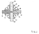
図1にはディファレンシャルキャリア11が示されており、このディファレンシャルキャリア11は、ディファレンシャルギヤのケーシング内で回動可能に支承することができるようになっている。この場合に支承は特に2つのスリーブ突出部12,13で行われ、これらのスリーブ突出部12,13はディファレンシャルキャリアの軸線方向Aに対して同軸的に形成されている。このディファレンシャルキャリア11は、一体的に成形されたフランジ16を有するポット状の第1の部分14と、この第1の部分14内に挿入されるカバー15とから成っている。前記フランジには、ディファレンシャルキャリアを回動するように駆動させるための大歯車(リングギア)がねじ止め可能である。第1のスリーブ突出部12は第1の部分14に一体的に結合されており、第2のスリーブ突出部13はカバー15に一体的に結合されている。カバー15は固定リング17によりポット状の部分14内に設けられた段部に対して接触して保持されている。固定リング17は外側へ向いた円錐面を有しており、これにより、カバー15は遊びなしに第1の部分14内に嵌め込まれている。ディファレンシャルキャリア11内には、長手方向軸線Aに対して同軸的に配置された2つの出力歯車18,19並びに長手方向軸線に対してそれぞれ半径方向に位置する回転軸を有する4つの補償傘歯車が配置されており、これら補償傘歯車の内の2つの補償傘歯車(22,23)のみを図面では見ることができる。これらの4つの補償傘歯車は両方の出力傘歯車18,19に噛合い係合しており、周にわたって一様に分配されて配置されている。図面に見ることのできる2つの補償傘歯車22,23はそれぞれ滑動する形で2つの支承ピン26,27上を走行し、これらの支承ピン26,27は第1の部分14内に設けられた半径方向の孔30,31内に差し込まれており、固定リング32,33により、半径方向外側でこれらの固定リング32,33内で保持されている。直径を減じられた内側の端部28,29により、2つの支承ピン26,27は互いで直接に支持されている。この場合にこれらのピンは、のちにはじめて説明することのできる第1の支承ピン24,25対により側方で支持され、互いに対して相対的に保持される。ここに図示した構成ではディファレンシャルキャリア11は、例えばドイツ連邦共和国特許第19619891号明細書で出願人が記載しているような、遮断可能なディファレンシャルギヤの一種であり、多板クラッチ41及び粘性ポンプ装置(Scherpumpenanordnung)51を有している。それ故、重要な個別部分にのみ言及する。多板クラッチ41は、ケーシング部分14に回動不能に結合された第1の多板と、クラッチハブ43に結合された第2の多板とから成る多板パッケージ42を有している。この多板パッケージ42は、粘性ポンプ装置51の調整ピストン52により軸線方向に負荷された場合には第1の部分内に設けられた支持ディスク44で軸線方向に支持される。さらに粘性ポンプ51はポンプハブ53に結合された剪断ディスク54と、同時にポンプケーシングを形成しているカバー部分15に対して制限されて回動可能な剪断溝・制御エレメント55とを有している。カバー部分15内にはポンプ室60が形成されており、このポンプ室60内には剪断ディスク54及び剪断溝・制御エレメント55が挿入されている。さらにカバー部分15内にはリング室56、リングカバー57及び皿ばね58より形成されたリザーバ61を見ることができ、このリザーバ61は、図示していない孔を介して粘性ポンプ51のポンプ室60に結合されている。出力傘歯車18は内側歯列34を有しており、この内側歯列34内へは第1の側方軸を差し込むことができる。出力傘歯車19は第2の内側歯列35を有しており、この内側歯列35内へは第2の側方軸を差し込むことができる。内側歯列35と一致する形で、クラッチハブ43の内側歯列45及びポンプハブ53の内側歯列59が形成されている。第2の側方軸の差込みにより、出力傘歯車19、クラッチハブ43及びポンプハブ53は互いに回動不能に結合される。その結果として、出力傘歯車19とディファレンシャルキャリア11との間に回転数差が生じた場合には粘性ポンプ51内に圧力が形成され、この圧力によりピストン52が多板パッケージ42に対して摺動され、これにより、出力傘歯車19はディファレンシャルキャリア11に対して制動される。ピストン52及びカバー15がシール62,63によりポンプハブ53に対してシールされている。出力傘歯車18及びポンプハブ53が、滑動ディスク36,37を介してディファレンシャルキャリア11に対して軸線方向にわずかな摩擦で支持されている。
FIG. 1 shows a differential carrier 11, which can be rotatably supported in a differential gear casing. In this case, the support is carried out in particular with two
図2には、補償傘歯車20,21,22,23及び支承ピン24,25,26,27がサブアセンブリとして長手方向軸線A(ここに図示していない)の方向に見た図で示されている。この場合には第1のピン24,25が一体的に形成されており、横方向孔38を有しており、この横方向孔38内には内側の第1の区分28,29を有する第2のピン26,27がほぼ遊びなしに差込み可能になっており、これにより、第2のピン26,27は長手方向延びに対して横方向に固定されている。さらに第2のピン26,27は互いに無関係に構成されており、内側の第1の区分28,29により互いに面状に突き合わされる。図1に示したディファレンシャルキャリア11の構成形式及びここに示した支承ピン及び差動歯車の装置により、カバー15がまだ組み付けられていない状態で差動歯車20,21,22,23を第1のハウジング部分14内へ挿入することができ、それからまずユニット式のピン装置24,25が横方向にディファレンシャルキャリア11内へ挿入され、この場合に補償傘歯車20,21が支承ピンに通され、最後にピン26,27が半径方向にディファレンシャルキャリア内へ差し込まれ、この場合に補償傘歯車22,23は支承ピンに通され、これらの支承ピンは半径方向孔38内へ相互に当接するまで差し込まれる。そののちに支承ピン24,25,26,27は固定リングによりディファレンシャルキャリア内で固定することができる。
In FIG. 2, the compensating
図3では、図2と等しい詳細部分には等しい符号を付す。この点では前記説明に関連している。ピンクロス装置のみが示されている。斜線により、ピン26,27に沿って潤滑溝68,69が示されている。
In FIG. 3, the same reference numerals are given to the same detailed portions as those in FIG. This point is related to the above description. Only the pin-cross device is shown. Lubricated grooves 68 and 69 are shown along the
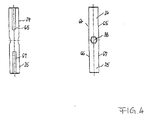
図4には、一体的に形成された、横方向孔38を有するピン対24,25が詳細に示されている。さらに差動歯車支承部の領域内には、ピンにそれぞれ1対の面取り部64,65,66,67を見ることができる。これらの面取り部対は差動歯車の支承部の領域に潤滑剤を供給するために働く。
FIG. 4 shows in detail a pair of
図5では、支承ピン26,27の1つを詳細に2つの側面図で見ることができる。この場合に内側の端部28、29に設けられた直径減衰部及び斜めの周囲の溝の形で構成された潤滑剤溝68、69を見ることができ、これらの潤滑溝68,69は同様に差動歯車の下方に潤滑剤を供給するために働く。 In FIG. 5, one of the bearing pins 26, 27 can be seen in detail in two side views. In this case, it is possible to see the lubricant grooves 68, 69 configured in the form of a diameter-attenuating part provided on the inner ends 28, 29 and an oblique circumferential groove, which are similar. It works to supply lubricant below the differential gear.
図4及び図5による潤滑剤溝の形式は交換することもできる。又は潤滑剤溝全体を一致して図4に示した溝の形式又は図5に示した溝の形式で、全ての支承ピン内に構成することができる。 The form of the lubricant groove according to FIGS. 4 and 5 can also be exchanged. Alternatively, the entire lubricant groove can be configured in all bearing pins in the form of the groove shown in FIG. 4 or in the form of the groove shown in FIG.
図6には、サブアセンブリの形の補償傘歯車20,21,22と支承ピン24,25,26とから成る装置の第2の構成が長手方向軸線Aの方向に見た図で示されている。この場合に図2と等しい詳細部分には等しい符号を付す。この点では前記説明に関連している。図6による装置は、3つのピン24,25,26しか設けられていないことによってのみ異なっている。この場合に2つの第1のピン24,25は一体的に形成されており、横方向孔38を有しており、この横方向孔38内には第1の区分28を有する第2のピン26が差し込まれている。この構成はより安価に作製可能である。なぜならば、所属の差動歯車を有する1つの支承ピンを省略することができるからである。アンバランスはディファレンシャルキャリア(ここには図示していない)内の対応した質量分配により補償することができる。
FIG. 6 shows a second arrangement of the device comprising the compensating
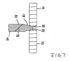
図7では、図6と等しい詳細部分には等しい符号を付す。この点では前記説明に関連している。ピンクロス装置のみが示されている。斜線により、ピン26に沿って潤滑剤溝68が示されている。
In FIG. 7, the same reference numerals are given to the same detailed portions as those in FIG. This point is related to the above description. Only the pin-cross device is shown. Lubricant grooves 68 are shown along the
図8は、上に述べた構成のいずれか1つによる第2のピン26,27の1つの内側の端部を示している。この第2のピン26は、第1のピン24,25(ここには図示していない)の横方向孔38内へ差し込むための減衰された直径dを備えた第1の区分28と、所属の差動歯車22を支承するためのより大きい直径Dを備えた第2の区分39と、これらの第1の区分28と第2の区分39とを接続する移行区分46とを有しており、この移行区分46は、第2の区分39の方向に連続的に増大する直径を有している。この場合、第1の区分28の直径dは横方向孔38の直径にほぼ対応しており、この場合にピンと孔との間には隙間ばめが形成されている。第1の区分28の第1の直径dと第2の区分39の第2の直径Dとの比率は0.4〜0.6までの間、すなわち、0.4≦d/D≦0.6である。この比率により、横方向孔38を有するピン24,25の剛性に対して、差し込まれたピン26の最適な剛性が生じる。さらに移行区分46が第1の区分28に隣接して第1の曲率半径R1を有しており、第2の区分39に隣接して第2の曲率半径R2を有していることが判る。曲率半径R1及びR2は特に大きく選択されており、これにより、切欠き効果が最小化され、一様な応力分配が達成される。それ故、第1の曲率半径R1と、第2の区分39の直径Dとの比率は、0.4〜0.6までの間であり、この場合に限界値は含まれている、すなわち、0.4≦R1/D≦0.6である。第2の曲率半径R2と直径Dとの間の比率のためにも、移行区分46と第2の区分39との間の最適な応力変化のためには0.4≦R2/D≦0.6が成り立つ。移行区分46の円錐形の周面と、ピン軸線との間に形成された角度aは、移行区分46を覆う仮想円錐面48とピン軸線との間に形成される角度よりも小さい。すなわち、
a≦arctan(0.5・(D−d)/L)
となり、この場合にLは移行区分46の長さである。このような変化により、同様に特に高い剛性及び良好な応力分配が生じる。
FIG. 8 shows the inner end of one of the second pins 26, 27 according to any one of the configurations described above. This
a ≦ arctan (0.5 · (D−d) / L)
Where L is the length of the
11 ディファレンシャルキャリア、 12,13 支承スリーブ、 14 ポット、 15 カバー、 16 フランジ、 17 固定リング、 18,19 出力傘歯車、 20,21,22,23 補償傘歯車、 24,25,26,27 支承ピン、 28,29 内側の端部/第1の区分、 30,31 孔、 32,33 固定リング、 34,35 内側歯列、 36,37 滑動ディスク、 38 横方向孔、 39,40 第2の区分、 41 多板クラッチ、 42 多板パケット、 43 クラッチハブ、 44支持プレート、 45 内側歯列、 46,47 移行区分、 48 円錐面、 51 粘性ポンプ、 52 ピストン、 53 ポンプハブ、 54 ポンプディスク、 55 剪断溝・制御エレメント、 56 リング室、 57 リングカバー、 58 皿ばね、 59 内側歯列、 60 ポンプ室、 61 リザーバ、 62,63 シール、 64,65,66,67 面取り部、 68,69 潤滑剤溝
11 differential carrier, 12, 13 bearing sleeve, 14 pot, 15 cover, 16 flange, 17 fixing ring, 18, 19 output bevel gear, 20, 21, 22, 23 compensating bevel gear, 24, 25, 26, 27
Claims (15)
複数の差動歯車(20,21,22,23)を有しており、該差動歯車が、長手方向軸線Aに対して半径方向にディファレンシャルキャリア(11)内で保持された少なくとも3つの支承ピン(24,25,26,27)を有するピンクロスに回動可能に配置されており、それぞれ出力歯車(18,19)に噛合い係合しており、
ピンクロスの互いに向かい合った2つの第1の支承ピン(24,25)が互いに結合されており、少なくとも1つの中央の横方向孔(38)を形成しており、
ピンクロスの少なくとも1つの第2の支承ピン(26,27)が、前記第1の支承ピン(24,25)とは別個に構成されており、少なくとも1つの横方向開口(38)内に差し込むための第1の直径(d)を備えた第1の区分(28,29)と、所属の差動歯車(22,23)を収容するためのより大きい第2の直径(D)を備えた第2の区分(39,40)と、前記第1の区分(28,29)と第2の区分(39,40)とを接続する、連続的に増大する直径を備えた移行区分(46,47)とを有していることを特徴とする、ディファレンシャルギヤのためのディファレンシャルキャリア(11)。 A differential carrier (11) for a differential gear, wherein the differential carrier (11) is rotatably supported about a longitudinal axis A, and can be driven to rotate. The differential carrier (11) has two output gears (18, 19) which are supported in the differential carrier (11) coaxially with respect to the longitudinal axis A. Has been
A plurality of differential gears (20, 21, 22, 23), the differential gears being held in the differential carrier (11) in a radial direction relative to the longitudinal axis A. It is rotatably arranged in a pin cross having pins (24, 25, 26, 27), and meshes with and engages with output gears (18, 19), respectively.
Two first bearing pins (24, 25) of the pin cross facing each other are joined together to form at least one central lateral hole (38);
The at least one second bearing pin (26, 27) of the pin cross is configured separately from the first bearing pin (24, 25) and is inserted into at least one lateral opening (38). A first section (28, 29) with a first diameter (d) and a second second diameter (D) with a larger second diameter (D) to accommodate the associated differential gear (22, 23). Transition section (46, 47) with a continuously increasing diameter connecting two sections (39, 40) and said first section (28, 29) and second section (39, 40). A differential carrier for a differential gear (11).
Applications Claiming Priority (2)
| Application Number | Priority Date | Filing Date | Title |
|---|---|---|---|
| DE10348546 | 2003-10-20 | ||
| PCT/EP2004/011716 WO2005040641A1 (en) | 2003-10-20 | 2004-10-18 | Differential axes of coordinates for a differential gear |
Publications (2)
| Publication Number | Publication Date |
|---|---|
| JP2007509288A true JP2007509288A (en) | 2007-04-12 |
| JP2007509288A5 JP2007509288A5 (en) | 2007-10-11 |
Family
ID=34223573
Family Applications (1)
| Application Number | Title | Priority Date | Filing Date |
|---|---|---|---|
| JP2006534718A Pending JP2007509288A (en) | 2003-10-20 | 2004-10-18 | Differential shaft cross for differential gear |
Country Status (8)
| Country | Link |
|---|---|
| US (1) | US7563190B2 (en) |
| EP (1) | EP1676056B1 (en) |
| JP (1) | JP2007509288A (en) |
| CN (1) | CN100516592C (en) |
| AT (1) | ATE363040T1 (en) |
| DE (2) | DE502004003908D1 (en) |
| PL (1) | PL1676056T3 (en) |
| WO (1) | WO2005040641A1 (en) |
Families Citing this family (19)
| Publication number | Priority date | Publication date | Assignee | Title |
|---|---|---|---|---|
| DE102005024455B4 (en) * | 2005-05-24 | 2007-03-08 | Gkn Driveline International Gmbh | Crown wheel and differential assembly with a crown wheel |
| DE202005021401U1 (en) * | 2005-08-08 | 2007-11-22 | Gkn Driveline International Gmbh | Differential arrangement with one-piece differential carrier and four differential gears |
| JP2007064381A (en) * | 2005-08-31 | 2007-03-15 | Musashi Seimitsu Ind Co Ltd | Differential device |
| US8083628B2 (en) * | 2009-01-19 | 2011-12-27 | GM Global Technology Operations LLC | Differential carrier assembly for a vehicle |
| CN101900168B (en) * | 2009-07-14 | 2012-04-18 | 昆山威创精密机械有限公司 | Connecting shaft structure of cross shaft universal joint |
| DE102010022344A1 (en) * | 2010-06-01 | 2011-12-01 | Gkn Driveline Deutschland Gmbh | Self-locking center crown gear differential for e.g. motor car, has actuators coordinated with respect to each other, so that operating elements are not in contact with wheel and outer disk, in respective switching states |
| DE102010063692A1 (en) | 2010-08-05 | 2012-02-09 | Continental Teves Ag & Co. Ohg | Method and circuit arrangement for checking the rotor position of a synchronous machine |
| CN101988563B (en) * | 2010-11-05 | 2013-03-13 | 东莞市明慧管理咨询有限公司 | Differential coupling continuously-variable automatic transmission |
| DE102010055928A1 (en) * | 2010-12-23 | 2012-06-28 | Daimler Ag | Motor vehicle differential device for drive train of motor vehicle, has two coaxially arranged output gear wheels and three differential gear wheels, which are meshed with output gear wheels |
| EP2655936A1 (en) * | 2010-12-23 | 2013-10-30 | Neumayer Tekfor Holding GmbH | Differential gear |
| US10100911B2 (en) | 2011-09-06 | 2018-10-16 | Eaton Intelligent Power Limited | Modular cross shaft yoke |
| US9303750B2 (en) | 2011-09-06 | 2016-04-05 | Eaton Corporation | Modular cross shaft yoke |
| JP6245462B2 (en) * | 2013-11-26 | 2017-12-13 | ジー・ケー・エヌ オートモーティヴ リミテッドGKN Automotive Limited | Fitting assembly and differential assembly |
| DE102014221408A1 (en) * | 2014-10-22 | 2016-04-28 | Zf Friedrichshafen Ag | differential |
| WO2017124371A1 (en) * | 2016-01-21 | 2017-07-27 | Volvo Construction Equipment Ab | Differential locking system in inboard wet brake axle |
| DE102016221722A1 (en) * | 2016-11-07 | 2018-05-09 | Zf Friedrichshafen Ag | Differential device and a vehicle with the differential device |
| DE102017106665B4 (en) | 2017-03-28 | 2018-12-06 | Gkn Automotive Ltd. | Pin arrangement for a differential gear and differential gear with such a pin arrangement |
| CN108361346B (en) * | 2018-02-24 | 2019-11-12 | 潍坊学院 | Limited-slip differential |
| DE102021004047A1 (en) | 2021-02-01 | 2022-01-27 | Daimler Ag | Differential gear for an axle of a motor vehicle, and electric axle drive |
Citations (8)
| Publication number | Priority date | Publication date | Assignee | Title |
|---|---|---|---|---|
| US3894447A (en) * | 1973-12-20 | 1975-07-15 | Deere & Co | Four-pinion differential |
| JPS55142736U (en) * | 1979-03-31 | 1980-10-13 | ||
| JPS57101150A (en) * | 1980-10-24 | 1982-06-23 | Ford Motor Co | Axle differential gear |
| JPH04244638A (en) * | 1991-01-29 | 1992-09-01 | Kubota Corp | Diff-lock mechanism for differential gear |
| JPH08100651A (en) * | 1995-10-12 | 1996-04-16 | Nippon Seiko Kk | Driving shaft of water pump for automobile |
| JPH09229037A (en) * | 1996-02-27 | 1997-09-02 | Suzuki Motor Corp | Bolt construction |
| JPH1151062A (en) * | 1997-08-07 | 1999-02-23 | Nippon Seiko Kk | Pin type retainer for rolling bearing |
| JP2001153126A (en) * | 1999-11-26 | 2001-06-08 | Toray Ind Inc | Stepped structure frp-made propeller shaft |
Family Cites Families (9)
| Publication number | Priority date | Publication date | Assignee | Title |
|---|---|---|---|---|
| US2720797A (en) * | 1954-02-19 | 1955-10-18 | Huddleston Leo Delmar | V-belt drive differential gear mechanisms |
| DE1827697U (en) * | 1957-01-22 | 1961-03-02 | Kloeckner Humboldt Deutz Ag | BEVEL GEAR PLANETARY GEAR. |
| US3974717A (en) * | 1974-12-19 | 1976-08-17 | Allis-Chalmers Corporation | Four pinion differential |
| DE3634394A1 (en) * | 1985-10-17 | 1987-04-23 | Volkswagen Ag | Retaining device |
| DE4424202C1 (en) * | 1994-07-09 | 1996-04-04 | Gkn Viscodrive Gmbh | Automotive differential with bevel gears and lock |
| DE19619891C2 (en) * | 1996-05-17 | 2001-07-26 | Gkn Viscodrive Gmbh | Device for controlling a clutch |
| ES2163815T3 (en) | 1997-03-12 | 2002-02-01 | Volkswagen Ag | DIFFERENTIAL GEAR, ESPECIALLY FOR THE OPERATION OF A SHAFT OF A MOTOR VEHICLE. |
| DE19919515C2 (en) * | 1999-04-29 | 2003-06-26 | Man Nutzfahrzeuge Ag | Bevel gear differential for commercial vehicles |
| US7081065B2 (en) * | 2003-02-21 | 2006-07-25 | Tochigi Fuji Sangyo Kabushiki Kaisha | Differential apparatus |
-
2004
- 2004-10-18 JP JP2006534718A patent/JP2007509288A/en active Pending
- 2004-10-18 EP EP04790549A patent/EP1676056B1/en active Active
- 2004-10-18 US US10/576,406 patent/US7563190B2/en active Active
- 2004-10-18 DE DE502004003908T patent/DE502004003908D1/en active Active
- 2004-10-18 DE DE202004016178U patent/DE202004016178U1/en not_active Expired - Lifetime
- 2004-10-18 WO PCT/EP2004/011716 patent/WO2005040641A1/en active IP Right Grant
- 2004-10-18 CN CNB2004800307705A patent/CN100516592C/en active Active
- 2004-10-18 AT AT04790549T patent/ATE363040T1/en active
- 2004-10-18 PL PL04790549T patent/PL1676056T3/en unknown
Patent Citations (8)
| Publication number | Priority date | Publication date | Assignee | Title |
|---|---|---|---|---|
| US3894447A (en) * | 1973-12-20 | 1975-07-15 | Deere & Co | Four-pinion differential |
| JPS55142736U (en) * | 1979-03-31 | 1980-10-13 | ||
| JPS57101150A (en) * | 1980-10-24 | 1982-06-23 | Ford Motor Co | Axle differential gear |
| JPH04244638A (en) * | 1991-01-29 | 1992-09-01 | Kubota Corp | Diff-lock mechanism for differential gear |
| JPH08100651A (en) * | 1995-10-12 | 1996-04-16 | Nippon Seiko Kk | Driving shaft of water pump for automobile |
| JPH09229037A (en) * | 1996-02-27 | 1997-09-02 | Suzuki Motor Corp | Bolt construction |
| JPH1151062A (en) * | 1997-08-07 | 1999-02-23 | Nippon Seiko Kk | Pin type retainer for rolling bearing |
| JP2001153126A (en) * | 1999-11-26 | 2001-06-08 | Toray Ind Inc | Stepped structure frp-made propeller shaft |
Also Published As
| Publication number | Publication date |
|---|---|
| PL1676056T3 (en) | 2007-11-30 |
| WO2005040641A1 (en) | 2005-05-06 |
| EP1676056B1 (en) | 2007-05-23 |
| CN1871461A (en) | 2006-11-29 |
| US20080032847A1 (en) | 2008-02-07 |
| DE502004003908D1 (en) | 2007-07-05 |
| EP1676056A1 (en) | 2006-07-05 |
| CN100516592C (en) | 2009-07-22 |
| ATE363040T1 (en) | 2007-06-15 |
| US7563190B2 (en) | 2009-07-21 |
| DE202004016178U1 (en) | 2005-02-24 |
Similar Documents
| Publication | Publication Date | Title |
|---|---|---|
| JP2007509288A (en) | Differential shaft cross for differential gear | |
| US7909140B2 (en) | Lubricating structure of planetary gear mechanism | |
| US4407170A (en) | Speed change device | |
| KR100901608B1 (en) | Gearshift Transmission for a Motor Vehicle Having a Hydraulically Actuatable Dual Clutch | |
| JP5155174B2 (en) | Torsional vibration damper coupled to crankshaft and combination of torsional vibration damper and clutch | |
| JP4798200B2 (en) | Automatic transmission and axial clearance adjustment method thereof | |
| JP5152162B2 (en) | Lubrication structure of transmission mechanism | |
| JP5063027B2 (en) | Clutch arrangement structure arranged in the radial direction | |
| US10378615B2 (en) | Clutch and speed change device including the same | |
| FR2806140A1 (en) | DIVIDED STEERING WHEEL | |
| JP6037015B2 (en) | Power transmission device | |
| JP4420115B2 (en) | Power transmission mechanism | |
| KR20080097212A (en) | Planetary gear set | |
| JP2012082923A (en) | Torque fluctuation absorbing device | |
| FR2844856A1 (en) | Motor vehicle transmission filter has torsion damper with radial coil springs of variable rigidity | |
| JP3486737B2 (en) | Torsion damper | |
| JP5337755B2 (en) | Lubricating oil passage structure of automatic transmission | |
| US5105680A (en) | Damped double flywheel for a motor vehicle | |
| JP2019143652A (en) | Differential device | |
| JP4594318B2 (en) | Differential carrier with improved strength | |
| US11162541B2 (en) | Torque transmission apparatus | |
| JP2003049932A (en) | Carrier assembly of planetary gear | |
| CN219734022U (en) | Clutch module | |
| JP7273781B2 (en) | Internal meshing planetary gear system | |
| WO2023248312A1 (en) | Continuously variable transmission |
Legal Events
| Date | Code | Title | Description |
|---|---|---|---|
| A521 | Request for written amendment filed |
Free format text: JAPANESE INTERMEDIATE CODE: A523 Effective date: 20070820 |
|
| A621 | Written request for application examination |
Free format text: JAPANESE INTERMEDIATE CODE: A621 Effective date: 20070820 |
|
| A621 | Written request for application examination |
Free format text: JAPANESE INTERMEDIATE CODE: A621 Effective date: 20070820 |
|
| A977 | Report on retrieval |
Free format text: JAPANESE INTERMEDIATE CODE: A971007 Effective date: 20100621 |
|
| A131 | Notification of reasons for refusal |
Free format text: JAPANESE INTERMEDIATE CODE: A131 Effective date: 20100624 |
|
| A601 | Written request for extension of time |
Free format text: JAPANESE INTERMEDIATE CODE: A601 Effective date: 20100924 |
|
| A602 | Written permission of extension of time |
Free format text: JAPANESE INTERMEDIATE CODE: A602 Effective date: 20101001 |
|
| A601 | Written request for extension of time |
Free format text: JAPANESE INTERMEDIATE CODE: A601 Effective date: 20101025 |
|
| A602 | Written permission of extension of time |
Free format text: JAPANESE INTERMEDIATE CODE: A602 Effective date: 20101101 |
|
| A601 | Written request for extension of time |
Free format text: JAPANESE INTERMEDIATE CODE: A601 Effective date: 20101124 |
|
| A602 | Written permission of extension of time |
Free format text: JAPANESE INTERMEDIATE CODE: A602 Effective date: 20101206 |
|
| A521 | Request for written amendment filed |
Free format text: JAPANESE INTERMEDIATE CODE: A523 Effective date: 20101217 |
|
| RD04 | Notification of resignation of power of attorney |
Free format text: JAPANESE INTERMEDIATE CODE: A7424 Effective date: 20101228 |
|
| A02 | Decision of refusal |
Free format text: JAPANESE INTERMEDIATE CODE: A02 Effective date: 20110121 |