EP1675439A2 - Leuchte zum Pulsbetrieb - Google Patents
Leuchte zum Pulsbetrieb Download PDFInfo
- Publication number
- EP1675439A2 EP1675439A2 EP05077941A EP05077941A EP1675439A2 EP 1675439 A2 EP1675439 A2 EP 1675439A2 EP 05077941 A EP05077941 A EP 05077941A EP 05077941 A EP05077941 A EP 05077941A EP 1675439 A2 EP1675439 A2 EP 1675439A2
- Authority
- EP
- European Patent Office
- Prior art keywords
- led
- lamp assembly
- lamp
- connector
- leds
- Prior art date
- Legal status (The legal status is an assumption and is not a legal conclusion. Google has not performed a legal analysis and makes no representation as to the accuracy of the status listed.)
- Withdrawn
Links
- 239000003990 capacitor Substances 0.000 claims abstract description 24
- 238000006073 displacement reaction Methods 0.000 claims description 4
- 238000009413 insulation Methods 0.000 claims description 4
- 238000000034 method Methods 0.000 claims description 2
- 238000002788 crimping Methods 0.000 claims 1
- 239000011159 matrix material Substances 0.000 abstract description 2
- 238000007599 discharging Methods 0.000 description 6
- 238000005286 illumination Methods 0.000 description 3
- 241001270131 Agaricus moelleri Species 0.000 description 1
- 238000010586 diagram Methods 0.000 description 1
- 210000003195 fascia Anatomy 0.000 description 1
- 230000004927 fusion Effects 0.000 description 1
- 238000012886 linear function Methods 0.000 description 1
- 230000007246 mechanism Effects 0.000 description 1
- 230000004048 modification Effects 0.000 description 1
- 238000012986 modification Methods 0.000 description 1
- 238000005476 soldering Methods 0.000 description 1
Images


Classifications
-
- H—ELECTRICITY
- H05—ELECTRIC TECHNIQUES NOT OTHERWISE PROVIDED FOR
- H05B—ELECTRIC HEATING; ELECTRIC LIGHT SOURCES NOT OTHERWISE PROVIDED FOR; CIRCUIT ARRANGEMENTS FOR ELECTRIC LIGHT SOURCES, IN GENERAL
- H05B45/00—Circuit arrangements for operating light-emitting diodes [LED]
- H05B45/30—Driver circuits
- H05B45/357—Driver circuits specially adapted for retrofit LED light sources
-
- F—MECHANICAL ENGINEERING; LIGHTING; HEATING; WEAPONS; BLASTING
- F21—LIGHTING
- F21V—FUNCTIONAL FEATURES OR DETAILS OF LIGHTING DEVICES OR SYSTEMS THEREOF; STRUCTURAL COMBINATIONS OF LIGHTING DEVICES WITH OTHER ARTICLES, NOT OTHERWISE PROVIDED FOR
- F21V19/00—Fastening of light sources or lamp holders
- F21V19/001—Fastening of light sources or lamp holders the light sources being semiconductors devices, e.g. LEDs
-
- F—MECHANICAL ENGINEERING; LIGHTING; HEATING; WEAPONS; BLASTING
- F21—LIGHTING
- F21V—FUNCTIONAL FEATURES OR DETAILS OF LIGHTING DEVICES OR SYSTEMS THEREOF; STRUCTURAL COMBINATIONS OF LIGHTING DEVICES WITH OTHER ARTICLES, NOT OTHERWISE PROVIDED FOR
- F21V23/00—Arrangement of electric circuit elements in or on lighting devices
-
- F—MECHANICAL ENGINEERING; LIGHTING; HEATING; WEAPONS; BLASTING
- F21—LIGHTING
- F21V—FUNCTIONAL FEATURES OR DETAILS OF LIGHTING DEVICES OR SYSTEMS THEREOF; STRUCTURAL COMBINATIONS OF LIGHTING DEVICES WITH OTHER ARTICLES, NOT OTHERWISE PROVIDED FOR
- F21V33/00—Structural combinations of lighting devices with other articles, not otherwise provided for
- F21V33/008—Leisure, hobby or sport articles, e.g. toys, games or first-aid kits; Hand tools; Toolboxes
-
- H—ELECTRICITY
- H05—ELECTRIC TECHNIQUES NOT OTHERWISE PROVIDED FOR
- H05B—ELECTRIC HEATING; ELECTRIC LIGHT SOURCES NOT OTHERWISE PROVIDED FOR; CIRCUIT ARRANGEMENTS FOR ELECTRIC LIGHT SOURCES, IN GENERAL
- H05B45/00—Circuit arrangements for operating light-emitting diodes [LED]
- H05B45/50—Circuit arrangements for operating light-emitting diodes [LED] responsive to malfunctions or undesirable behaviour of LEDs; responsive to LED life; Protective circuits
-
- H—ELECTRICITY
- H05—ELECTRIC TECHNIQUES NOT OTHERWISE PROVIDED FOR
- H05B—ELECTRIC HEATING; ELECTRIC LIGHT SOURCES NOT OTHERWISE PROVIDED FOR; CIRCUIT ARRANGEMENTS FOR ELECTRIC LIGHT SOURCES, IN GENERAL
- H05B47/00—Circuit arrangements for operating light sources in general, i.e. where the type of light source is not relevant
- H05B47/10—Controlling the light source
-
- H—ELECTRICITY
- H10—SEMICONDUCTOR DEVICES; ELECTRIC SOLID-STATE DEVICES NOT OTHERWISE PROVIDED FOR
- H10H—INORGANIC LIGHT-EMITTING SEMICONDUCTOR DEVICES HAVING POTENTIAL BARRIERS
- H10H20/00—Individual inorganic light-emitting semiconductor devices having potential barriers, e.g. light-emitting diodes [LED]
-
- H—ELECTRICITY
- H05—ELECTRIC TECHNIQUES NOT OTHERWISE PROVIDED FOR
- H05B—ELECTRIC HEATING; ELECTRIC LIGHT SOURCES NOT OTHERWISE PROVIDED FOR; CIRCUIT ARRANGEMENTS FOR ELECTRIC LIGHT SOURCES, IN GENERAL
- H05B45/00—Circuit arrangements for operating light-emitting diodes [LED]
- H05B45/30—Driver circuits
- H05B45/37—Converter circuits
-
- Y—GENERAL TAGGING OF NEW TECHNOLOGICAL DEVELOPMENTS; GENERAL TAGGING OF CROSS-SECTIONAL TECHNOLOGIES SPANNING OVER SEVERAL SECTIONS OF THE IPC; TECHNICAL SUBJECTS COVERED BY FORMER USPC CROSS-REFERENCE ART COLLECTIONS [XRACs] AND DIGESTS
- Y02—TECHNOLOGIES OR APPLICATIONS FOR MITIGATION OR ADAPTATION AGAINST CLIMATE CHANGE
- Y02B—CLIMATE CHANGE MITIGATION TECHNOLOGIES RELATED TO BUILDINGS, e.g. HOUSING, HOUSE APPLIANCES OR RELATED END-USER APPLICATIONS
- Y02B20/00—Energy efficient lighting technologies, e.g. halogen lamps or gas discharge lamps
- Y02B20/30—Semiconductor lamps, e.g. solid state lamps [SSL] light emitting diodes [LED] or organic LED [OLED]
Definitions
- This invention relates to lamps, and in particular to the use of solid-state lamps to replace filament lamps in a wide range of applications where the filament bulb is conventionally driven with a pulsed power supply.
- Small filament lamps are used in a wide range of applications, including entertainment machines, electronic equipment and vehicle equipment both as indicator lamps and for more general illumination.
- the lamp is driven using a pulsed power supply in order to allow a number of lamps to be addressed sequentially so as to allow the lamps to be matrix addressed as part of a larger display, to reduce the complexity and cost of the drive electronics, and to reduce the number of connections to the lamp array.
- a pulsed light source appears to the eye as a steady time-independent light source.
- the long response time of the filament assists in producing this illusion.
- the power supply could have a duty cycle of 1/16, with the power on for 1ms and off for 15ms, giving a repetition frequency of about 63Hz, and hence giving illumination that appears constant to the eye.
- the eye averages the light output from the source, and so the light emitted by the source during the pulse must be greater than the required average light output by a factor equal to the duty cycle.
- the light output is a highly non-linear function of current, so that to achieve the high light output during the pulse, the current during the pulse is only a small factor greater than the steady current needed to give the same average light output. For example, for a duty cycle of 1/1.6, ideally the current during the pulse is only twice the equivalent steady current.
- Filament lamps are prone to failure after relatively short periods of operation. Such failures not only require time and resources to replace the lamps, but also mean that there are periods when the indication or illumination functions are not operational. In entertainment machines, for example, this will involve loss of revenue. For this reason, and for reasons of energy efficiency, filament lamps are being replaced in many applications by solid-state lamps, usually light-emitting diodes (LEDs). As usually supplied, these LEDs cannot be used as direct replacements for filament lamps because the connections are not the same and because the voltages needed to drive an LED and a filament lamp are different. However, direct replacement LEDs are now available commercially in which the LED is permanently attached in an assembly that provides contacts directly compatible with a lampholder designed for a filament lamp. In addition, resistors and protection devices can be included within the assembly to ensure that the LED can be driven from the same voltage source that is used for the filament bulb.
- LEDs light-emitting diodes
- LEDs are commercially successful because they are much more reliable, and also much more efficient, providing the same light output for a lower current and lower power dissipation.
- the use of LEDs in this way therefore reduces the cost of ownership of the system or machine in which they are installed because of reduced power requirements, reduced replacement costs, and because there is no loss of revenue or function as a result of failure.
- Pulsed operation of LEDs has been used extensively in the past, and there are a number of patents relating to this mode of operation. Invariably, however, the prior patents and applications are concerned with new drive or control circuits intended to achieve improved performance or reduced cost.
- patent US4673865 provides a method of generating a voltage sufficient to drive an LED from a low-voltage battery by using pulsed operation.
- US6400101 describes a drive circuit describes a drive circuit with a control loop containing a low-pass filter that allows an LED to be operated in pulse mode with a constant mean value of LED current.
- the invention described in this application is fundamentally different to previous inventions in that it describes the invention of a lamp assembly that is a direct replacement for a filament lamp in pulsed operation without requiring any modification to the power supplies used for filament lamps, thereby providing a cost-efficient and rapid means of replacement of filament bulbs by LEDs.
- This invention overcomes the problem of using an LED with a pulsed power supply by incorporating a charge storage device or integrating component, most conveniently an electrical capacitor, within the lamp assembly.
- the lamp assembly is a direct replacement for a filament bulb.
- current flows into the capacitor during the drive pulse, increasing the total charge in the capacitor and hence the voltage that appears across the capacitor. This charge and hence the voltage is controlled by the values of the capacitor and resistors in the circuit, and also by the length of the drive pulse.
- the capacitor discharges through one or more LEDs connected across the capacitor, at a rate determined by additional circuit components. With suitable choice of capacitor and resistor values the peak current through the LED is greatly reduced, increasing reliability to that expected for LEDs driven by a DC supply.
- the object of the present invention is to allow a single LED lamp assembly to replace a filament lamp together with the lampholder or socket in pulsed applications.
- the complete LED lamp assembly comprises one or more LEDs connected in an electrical circuit that contains one or more capacitors and resistors. Additional circuit components such as protection diodes can be included in the circuit. Different implementations of the invention are possible, such as one where the circuit components are hard wired between the LEDs and an insulation displacement connector (IDC) or other similar connector, and the IDC is connected directly to the wiring of the system or machine without any intermediate connectors.
- IDC insulation displacement connector
- the lamp assembly can be fabricated to allow direct attachment to the control panel, fascia board or other part of the entertainment machine or other system.
- the electrical components are hard wired within a lampholder that is connected to the system or machine, and one or more LEDs inserted in the lampholder.
- figure 1 shows the LED lamp 1 mounted on the insulation displacement connector 2, through a mechanical/electrical interface 3.
- the LED lamp 1 is shown as a four pin flat-top device, but any other LED structure is possible.
- the LED lamp 1 is soldered in this implementation to the capacitor 4 and also to resistors 5.
- the components are shown soldered to an insulation displacement connector (IDC) 2 in this implementation.
- IDC insulation displacement connector
- Other implementations are also possible in which the electrical contacts form part of the connector 2 which provide both mechanical support and electrical connection.
- the IDC 2 allows direct connection to the external circuit wires 6 without the need for soldering, giving a secure connection which can be made rapidly and easily.
- IDC connectors have proven reliability, and also provide a reproducible electrical and thermal connection.
- the essential feature of the invention shown in figure 1, is that in this implementation the lamp assembly contains a capacitor 4 and resistors 5 between the one or more LEDs and the wires 6 connecting the lampholder to the machine, giving an assembly that can be driven directly in pulsed operation.
- Figure 2 shows the top view of the assembly, where an LED chip 7 is mounted on the lead frame 8; together comprising the lamp 1.
- the lead frame has four pins and the LED package is flat-topped.
- Other versions are also possible, including a conventional round-top LED and a two-pin lead frame.
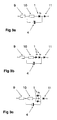
- FIG 3a shows the circuit symbol for the LED lamp 1 together with the capacitor 4, the charging resistor 9, the discharging resistor 10 and a protection diode 11.
- Figure 3b) shows two LEDs connected in series with the discharging resistor 10 across the capacitor 4, and figure 3c) shows two LEDs connected in parallel.
- the value of the discharging resistor 10 is less than the value of the resistor in figure 3a), leading to greater energy efficiency because less power is dissipated in the resistor 10.
- the rate at which the capacitor charges during the pulse is controlled primarily by the magnitude of the charging resistor 9 and the capacitor 4. If these two components give rise to a charging time that is significantly less than the pulse length, the capacitor 4 will be fully charged to the supply voltage during the pulse. At the end of the pulse the capacitor will discharge through resistor 10 and the LED 1 at a rate determined by the capacitor 4 and the discharging resistor 10. By adjusting the value of resistor 10 the current through the LED lamp 1 can be controlled to give the required light output.
- the voltage across the capacitor 4 in this operating regime is shown as a function of time in figure 4b), for the input voltage shown in figure 4a).
- the voltage shown in figure 4b) also appears across the series combination of the LED lamp 1 and the discharging resistor 10, and determines the LED current and light output.
- the charging time is sufficiently large, corresponding to larger values of the resistor 9, the voltage appearing across the capacitor at the end of the pulse will be a function of the length of the pulse. At the end of the pulse the current through the LED lamp 1 will therefore also be a function of pulse length, and so the length of the pulse can be used to control the light output from the LED.
- the voltage across the capacitor 4 is shown as a function of time in figure 4c) in this case of long charging times.
- the charging time is controlled by resistor 9 and the discharging time by resistor 10.
Landscapes
- Engineering & Computer Science (AREA)
- General Engineering & Computer Science (AREA)
- Circuit Arrangement For Electric Light Sources In General (AREA)
- Electroluminescent Light Sources (AREA)
Applications Claiming Priority (1)
| Application Number | Priority Date | Filing Date | Title |
|---|---|---|---|
| GB0427880A GB2421633B (en) | 2004-12-21 | 2004-12-21 | Lamp assembly for pulse operation |
Publications (2)
| Publication Number | Publication Date |
|---|---|
| EP1675439A2 true EP1675439A2 (de) | 2006-06-28 |
| EP1675439A3 EP1675439A3 (de) | 2008-06-11 |
Family
ID=34090387
Family Applications (1)
| Application Number | Title | Priority Date | Filing Date |
|---|---|---|---|
| EP05077941A Withdrawn EP1675439A3 (de) | 2004-12-21 | 2005-12-20 | Leuchte zum Pulsbetrieb |
Country Status (2)
| Country | Link |
|---|---|
| EP (1) | EP1675439A3 (de) |
| GB (1) | GB2421633B (de) |
Cited By (3)
| Publication number | Priority date | Publication date | Assignee | Title |
|---|---|---|---|---|
| EP2348793A1 (de) * | 2010-01-20 | 2011-07-27 | ATLAS Elektronik GmbH | Leuchtmittel mit LED und Treiberschaltung |
| EP2410817A3 (de) * | 2010-07-23 | 2014-05-21 | Advanced Connectek Inc. | Lichtemittierende Vorrichtungsantriebsschaltung |
| FR3002820A1 (fr) * | 2013-03-01 | 2014-09-05 | Valeo Vision | Module de pilotage de l'alimentation d'un bloc electrique d'un vehicule automobile |
Citations (2)
| Publication number | Priority date | Publication date | Assignee | Title |
|---|---|---|---|---|
| US4673865A (en) | 1986-04-04 | 1987-06-16 | Motorola, Inc. | Charge coupled LED driver circuit |
| US6400101B1 (en) | 1999-06-30 | 2002-06-04 | Patent-Treuhand-Gesellschaft Fuer Elektrische Gluehlampen Mbh | Control circuit for LED and corresponding operating method |
Family Cites Families (6)
| Publication number | Priority date | Publication date | Assignee | Title |
|---|---|---|---|---|
| US4346329A (en) * | 1979-08-27 | 1982-08-24 | Schmidt Robert C H | Aiming post light |
| CA1205931A (en) * | 1982-11-04 | 1986-06-10 | Integrated Systems Engineering, Inc. | Solid state display system and light emitting diode pixels therefor |
| US5559681A (en) * | 1994-05-13 | 1996-09-24 | Cnc Automation, Inc. | Flexible, self-adhesive, modular lighting system |
| AU4850099A (en) * | 1999-06-29 | 2001-01-31 | Welles Reymond | Ac powered led circuits for traffic signal displays |
| JP4353667B2 (ja) * | 1999-12-14 | 2009-10-28 | 株式会社タキオン | Ledランプ装置 |
| US7318661B2 (en) * | 2003-09-12 | 2008-01-15 | Anthony Catalano | Universal light emitting illumination device and method |
-
2004
- 2004-12-21 GB GB0427880A patent/GB2421633B/en not_active Expired - Lifetime
-
2005
- 2005-12-20 EP EP05077941A patent/EP1675439A3/de not_active Withdrawn
Patent Citations (2)
| Publication number | Priority date | Publication date | Assignee | Title |
|---|---|---|---|---|
| US4673865A (en) | 1986-04-04 | 1987-06-16 | Motorola, Inc. | Charge coupled LED driver circuit |
| US6400101B1 (en) | 1999-06-30 | 2002-06-04 | Patent-Treuhand-Gesellschaft Fuer Elektrische Gluehlampen Mbh | Control circuit for LED and corresponding operating method |
Cited By (3)
| Publication number | Priority date | Publication date | Assignee | Title |
|---|---|---|---|---|
| EP2348793A1 (de) * | 2010-01-20 | 2011-07-27 | ATLAS Elektronik GmbH | Leuchtmittel mit LED und Treiberschaltung |
| EP2410817A3 (de) * | 2010-07-23 | 2014-05-21 | Advanced Connectek Inc. | Lichtemittierende Vorrichtungsantriebsschaltung |
| FR3002820A1 (fr) * | 2013-03-01 | 2014-09-05 | Valeo Vision | Module de pilotage de l'alimentation d'un bloc electrique d'un vehicule automobile |
Also Published As
| Publication number | Publication date |
|---|---|
| EP1675439A3 (de) | 2008-06-11 |
| GB2421633B (en) | 2007-02-14 |
| GB2421633A (en) | 2006-06-28 |
| GB0427880D0 (en) | 2005-01-19 |
Similar Documents
| Publication | Publication Date | Title |
|---|---|---|
| US8324642B2 (en) | Light emitting diode assembly and methods | |
| US10323838B2 (en) | LED tube lamp | |
| CN208107667U (zh) | 一种led直管灯、镇流器旁路型led直管灯及直管灯系统 | |
| US7015650B2 (en) | Circuit devices, circuit devices which include light emitting diodes, assemblies which include such circuit devices, flashlights which include such assemblies, and methods for directly replacing flashlight bulbs | |
| US6371636B1 (en) | LED light module for vehicles | |
| US7221105B2 (en) | Electromagnetic radiation emitting bulb and method using same in a portable device | |
| US20120313540A1 (en) | Light emitting apparatus | |
| US20020075677A1 (en) | Night light | |
| WO2005103555A1 (en) | A fluorescent bulb replacement with led system | |
| US9035570B2 (en) | LED-airfield light | |
| CN103190002A (zh) | Led 点亮电路、led 照明装置、以及led 照明部用插座 | |
| US9078309B2 (en) | LED fluorescent lamp | |
| JPH1187156A (ja) | 放電灯点灯装置 | |
| KR20120087140A (ko) | 발광 다이오드 및 발광 다이오드를 생산하기 위한 방법 | |
| EP1675439A2 (de) | Leuchte zum Pulsbetrieb | |
| CN105972464B (zh) | Led直管灯 | |
| US20160234909A1 (en) | Led lamp | |
| CN204704694U (zh) | Led照明灯具 | |
| JP5385815B2 (ja) | 点灯装置及びそれを用いた照明器具 | |
| KR101276356B1 (ko) | 발광다이오드 형광등 | |
| US20250212306A1 (en) | Signal generator module for dimming of a luminaire | |
| GB2409332A (en) | Lamp assembly for direct connection to system wiring | |
| CN214507430U (zh) | 一种驱动电路及照明模组 | |
| CN113170557B (zh) | 用于发光二极管led照明设备的照明器材 | |
| CN112566320B (zh) | 一种高功率因数低频闪的实现方法 |
Legal Events
| Date | Code | Title | Description |
|---|---|---|---|
| PUAI | Public reference made under article 153(3) epc to a published international application that has entered the european phase |
Free format text: ORIGINAL CODE: 0009012 |
|
| AK | Designated contracting states |
Kind code of ref document: A2 Designated state(s): AT BE BG CH CY CZ DE DK EE ES FI FR GB GR HU IE IS IT LI LT LU LV MC NL PL PT RO SE SI SK TR |
|
| AX | Request for extension of the european patent |
Extension state: AL BA HR MK YU |
|
| PUAL | Search report despatched |
Free format text: ORIGINAL CODE: 0009013 |
|
| AK | Designated contracting states |
Kind code of ref document: A3 Designated state(s): AT BE BG CH CY CZ DE DK EE ES FI FR GB GR HU IE IS IT LI LT LU LV MC NL PL PT RO SE SI SK TR |
|
| AX | Request for extension of the european patent |
Extension state: AL BA HR MK YU |
|
| STAA | Information on the status of an ep patent application or granted ep patent |
Free format text: STATUS: THE APPLICATION IS DEEMED TO BE WITHDRAWN |
|
| AKX | Designation fees paid | ||
| 18D | Application deemed to be withdrawn |
Effective date: 20080701 |
|
| REG | Reference to a national code |
Ref country code: DE Ref legal event code: 8566 |