EP1675251B1 - Moteur-tube pour jalousies - Google Patents
Moteur-tube pour jalousies Download PDFInfo
- Publication number
- EP1675251B1 EP1675251B1 EP05026432A EP05026432A EP1675251B1 EP 1675251 B1 EP1675251 B1 EP 1675251B1 EP 05026432 A EP05026432 A EP 05026432A EP 05026432 A EP05026432 A EP 05026432A EP 1675251 B1 EP1675251 B1 EP 1675251B1
- Authority
- EP
- European Patent Office
- Prior art keywords
- motor
- rotor
- accordance
- drive mechanism
- tube
- Prior art date
- Legal status (The legal status is an assumption and is not a legal conclusion. Google has not performed a legal analysis and makes no representation as to the accuracy of the status listed.)
- Not-in-force
Links
Images

Classifications
-
- H—ELECTRICITY
- H02—GENERATION; CONVERSION OR DISTRIBUTION OF ELECTRIC POWER
- H02K—DYNAMO-ELECTRIC MACHINES
- H02K21/00—Synchronous motors having permanent magnets; Synchronous generators having permanent magnets
- H02K21/12—Synchronous motors having permanent magnets; Synchronous generators having permanent magnets with stationary armatures and rotating magnets
- H02K21/22—Synchronous motors having permanent magnets; Synchronous generators having permanent magnets with stationary armatures and rotating magnets with magnets rotating around the armatures, e.g. flywheel magnetos
- H02K21/227—Synchronous motors having permanent magnets; Synchronous generators having permanent magnets with stationary armatures and rotating magnets with magnets rotating around the armatures, e.g. flywheel magnetos having an annular armature coil
-
- E—FIXED CONSTRUCTIONS
- E06—DOORS, WINDOWS, SHUTTERS, OR ROLLER BLINDS IN GENERAL; LADDERS
- E06B—FIXED OR MOVABLE CLOSURES FOR OPENINGS IN BUILDINGS, VEHICLES, FENCES OR LIKE ENCLOSURES IN GENERAL, e.g. DOORS, WINDOWS, BLINDS, GATES
- E06B9/00—Screening or protective devices for wall or similar openings, with or without operating or securing mechanisms; Closures of similar construction
- E06B9/56—Operating, guiding or securing devices or arrangements for roll-type closures; Spring drums; Tape drums; Counterweighting arrangements therefor
- E06B9/68—Operating devices or mechanisms, e.g. with electric drive
- E06B9/72—Operating devices or mechanisms, e.g. with electric drive comprising an electric motor positioned inside the roller
-
- H—ELECTRICITY
- H02—GENERATION; CONVERSION OR DISTRIBUTION OF ELECTRIC POWER
- H02K—DYNAMO-ELECTRIC MACHINES
- H02K21/00—Synchronous motors having permanent magnets; Synchronous generators having permanent magnets
- H02K21/12—Synchronous motors having permanent magnets; Synchronous generators having permanent magnets with stationary armatures and rotating magnets
- H02K21/22—Synchronous motors having permanent magnets; Synchronous generators having permanent magnets with stationary armatures and rotating magnets with magnets rotating around the armatures, e.g. flywheel magnetos
-
- H—ELECTRICITY
- H02—GENERATION; CONVERSION OR DISTRIBUTION OF ELECTRIC POWER
- H02K—DYNAMO-ELECTRIC MACHINES
- H02K7/00—Arrangements for handling mechanical energy structurally associated with dynamo-electric machines, e.g. structural association with mechanical driving motors or auxiliary dynamo-electric machines
- H02K7/14—Structural association with mechanical loads, e.g. with hand-held machine tools or fans
-
- H—ELECTRICITY
- H02—GENERATION; CONVERSION OR DISTRIBUTION OF ELECTRIC POWER
- H02K—DYNAMO-ELECTRIC MACHINES
- H02K16/00—Machines with more than one rotor or stator
Definitions
- the invention relates to a drive device according to the preamble of claim 1.
- Such drive devices are generally widely known. They work with electric current and have a stator wound with a coil arrangement and a rotor connected to the drive shaft. In many cases, the rotors have a coil arrangement, and the rotors are provided with slip rings and carbon pencils for supplying the rotor current, or the motors are designed as asynchronous motors.
- the drive device comprises in addition to the actual engine nor a Endabschaltech, a brake and a multi-stage planetary gear. With these drive devices, the torques required for blinds, awnings, shutters and the like can only be achieved by means of a high reduction ratio (> approximately 1: 100) having the transmission. at Single-phase capacitor motors, a speed control is also hardly possible. The speed of the drive devices is not constant, but load-dependent. Furthermore, the production of these drive devices is quite complicated and thus costly.
- transversal flux motors are known.
- a stator having an annular stator coil having a central axis and in which the stator coil is surrounded along its circumference of at least approximately C-shaped stator lamination.
- adjacent C-shaped stator lamination packages are directed alternately with the free ends of their legs radially inwardly and outwardly.
- the stator laminations are oriented at least in sections substantially tangentially to the center axis of the stator coil or to the circumference of the stator coil.
- the motor further comprises a rotor of a carrier connected to the drive shaft and at least one ring attached to the carrier of alternating magnetic poles, which face the legs of each adjacent stator lamination.
- a transverse flux motor can be used to produce very compact, low-speed motors with very high efficiency and high power in a simple manner.
- transverse flux motor which is formed with an external rotor and provided with a rotor having permanent magnets.
- multi-phase motors wherein at least one Genzousetrennteil is used, are attached to the stator on both sides, each with a coil assembly.
- the illustrated embodiments are also not suitable, because the external rotor are connected via a Ringerhemperetcmit the motor shaft and therefore the motor does not have the necessary compactness for a tubular motor.
- a transverse flux motor with C-shaped magnetic flux yokes are known, which additionally have at the air gap I-shaped magnetic flux yokes.
- transverse flux motors are used in particular in the automotive industry or in machine tools and are not intended for use in tubular motors for blinds, awnings, shutters and the like.
- the invention has for its object to provide a drive device referred to in the preamble of claim 1, which is more suitable for blinds, awnings, shutters and the like.
- the drive device according to the invention can be assembled in a confined space, as desired for the application, while working highly efficiently at high power density.
- the compact design increases the efficiency of the engine.
- the torque-dependent losses can be reduced become.
- the coils are concentric around the motor axis, which can therefore be easily manufactured.
- the tubular motor may comprise two or more single-phase motor parts, which are preferably formed substantially the same.
- the motor part used for a single-stage motor can be used multiple times as a basic module in multi-stage motors, so that drive devices higher power can be produced inexpensively.
- a further embodiment of the invention provides that the transverse flux motor is divided into a first motor part and a second motor part in that between the motor parts as part of the motor housing, a radially extending, provided with a central opening for the motor shaft separator, on both end sides each wound with a coil assembly stator is fixed, and on both sides of the separating part in each case a cross-sectionally C-shaped, provided on the motor shaft with its inner tube and the separating part opening rotor part is provided.
- a simple construction of the tubular motor is achieved.
- the inner tube of the rotor part is partially received in the central opening.
- the inner tube of the rotor part slides in the central opening.
- the motor shaft is supported by it.
- controls for the engine are housed in an end portion of the motor housing. These controls are mainly used for the end stop and the engine control and are operated electronically.
- the drive device can be operated directly by the mains voltage or alternatively with a low voltage.
- the motor is mechanically locked in the de-energized state for holding the load.
- conventional positive, frictional or non-positive locking devices such as those operating according to the Schlinfeder principle, solenoid principle or the like can be used.
- an electric drive device 1 is shown as it comes as a tubular motor in winding tubes of blinds, awnings, shutters and the like used.
- the drive device is equipped with a tubular housing 2, which has a first motor part 3, a second motor part 4 and a control part 5.
- the two motor parts 3 and 4 form a two-stage transversal flux motor, while the control part 5 accommodates the electronic controls required for the end shutdown and the control of the transverse flux motor, which are not described in detail.
- the housing 2 is are not described in detail.
- the housing 2 is provided with four screw feet, such as the screw feet 6-8.
- a motor shaft 9 is mounted at both end regions by means of ball bearings.
- the ends of the motor shaft 9 are each closed with a coupling piece 10 and 11 respectively.
- the motor housing 2 includes a housing cover 12, a middle first separation part 13 and a second separation part 14, which extend radially all three and are each provided with a central opening 15 or 16 and 17 respectively.
- the motor shaft 9 extends through the central openings 15-17.
- the transverse flux motor is divided into the two motor parts 3 and 4.
- stator sections 18, 19, each with a coil arrangement are fastened in the form of cylinders to both end faces in a manner not shown. These stator parts carry distributed over its circumference, not shown Flussleit Publishede in adjacent rows over the length of the stator.
- a cross-sectionally U-shaped first rotor part 20 with an inner tube 21 and an outer tube 22 is arranged between the housing cover 12 and the separating part 13.
- the inner tube 21 is mounted on the motor shaft 9, wherein it partially protrudes into the central openings 15, 16 and can exert there preferably sliding bearing functions.
- the inner side of the outer tube 22 is provided with distributed over its circumference of permanent magnet elements in rows, which lie next to each other over the length of this inner side.
- the permanent magnet elements are arranged with alternating polarity. These permanent magnet elements lie opposite the flux conducting pieces of the stator 18 with the formation of an air gap for the transverse flux.
- a second rotor part 23 is arranged between the separating part 13 and the separating part 14. Both rotor parts 20, 23 open to the separating part 13.
- the stator part 18 protrudes into the rotor part 20, while the stator part 19 projects into the rotor part 23. Due to the transversal magnetic flux, a force is generated which causes the rotor parts 20, 23 and thus the motor shaft 9 to rotate.
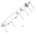
- FIG. 4 Another simpler embodiment of a drive device 1 'according to the invention for blinds or awnings is in Fig. 4 shown.
- the trained as an external rotor Transverse flux motor has only a single stator 24 and a single rotor 25, which are similar to the described stator 18, 19 and rotor parts 20, 23 are formed. This drive device is intended for smaller power.
- multistage transversal flux motors can also be used according to the Fig. 1 described principle are used, wherein the rotor parts and stator parts each have the same modular design.
Landscapes
- Engineering & Computer Science (AREA)
- Power Engineering (AREA)
- Structural Engineering (AREA)
- Architecture (AREA)
- Civil Engineering (AREA)
- Blinds (AREA)
- Operating, Guiding And Securing Of Roll- Type Closing Members (AREA)
- Yarns And Mechanical Finishing Of Yarns Or Ropes (AREA)
- Ultra Sonic Daignosis Equipment (AREA)
- Hydraulic Motors (AREA)
- Reciprocating, Oscillating Or Vibrating Motors (AREA)
Claims (7)
- Dispositif (1, 1') d'entraînement comprenant un moteur-tube entraîné électriquement et ayant un stator ( 18, 19, 24) et un rotor ( (20, 23, 25) pour des jalousies, des stores, des volets roulants et analogues,
caractérisé,
en ce que l'on utilise comme moteur-tube (3, 4) un moteur à flux transversal qui est sous la forme d'un induit extérieur et qui est muni d'un rotor (20, 23, 25) ayant un élément à aimant permanent. - Dispositif d'entraînement suivant la revendication 1,
caractérisé,
en ce que le moteur-tube a deux ou plusieurs parties (3, 4) de moteur monophasées, qui de préférence sont sensiblement identiques. - Dispositif d'entraînement suivant la revendication 1 ou 2,
caractérisé,
en ce que le moteur à flux transversal est subdivisé en une première partie (3) de moteur et en une deuxième partie (4) de moteur, en ce qu'entre les parties de moteur est prévue, en tant que partie du carter (2) de moteur, une partie (13) de séparation, qui s'étend radialement, qui est munie d'une ouverture (16) centrale pour l'arbre (9) du moteur et à laquelle est fixée des deux côtés frontaux respectivement une partie (18, 19) de stator enroulée d'un dispositif à bobine et des deux côtés de la partie de séparation respectivement une partie (20, 23) de rotor de section transversale en forme de U, 2 fixée sur l'arbre du moteur par son tube (21) intérieur et s'ouvrant vers la partie (13) de séparation. - Dispositif d'entraînement suivant la revendication 3,
caractérisé
en ce que le tube (21) intérieur de la partie (20) de rotor est reçue en partie dans l'ouverture (16) centrale. - Dispositif d'entraînement suivant la revendication 4,
caractérisé
en ce que le tube (21) intérieur de la partie (20) de rotor est monté dans l'ouverture (16) centrale. - Dispositif d'entraînement suivant l'une des revendications 2 à 5,
caractérisé
en ce que des éléments électroniques de commande du moteur sont logés dans une partie (5) d'extrémité ou dans la partie de séparation du carter (2) du moteur. - Dispositif d'entraînement suivant les revendications 1 à 6,
caractérisé
en ce que le moteur, à l'état sans courant, est, pour le maintien de la charge, verrouillé mécaniquement, notamment par des moyens fonctionnant suivant le principe du ressort enroulé.
Applications Claiming Priority (1)
| Application Number | Priority Date | Filing Date | Title |
|---|---|---|---|
| DE102004063067A DE102004063067A1 (de) | 2004-12-22 | 2004-12-22 | Antriebsvorrichtung |
Publications (2)
| Publication Number | Publication Date |
|---|---|
| EP1675251A1 EP1675251A1 (fr) | 2006-06-28 |
| EP1675251B1 true EP1675251B1 (fr) | 2008-02-27 |
Family
ID=35999555
Family Applications (1)
| Application Number | Title | Priority Date | Filing Date |
|---|---|---|---|
| EP05026432A Not-in-force EP1675251B1 (fr) | 2004-12-22 | 2005-12-03 | Moteur-tube pour jalousies |
Country Status (4)
| Country | Link |
|---|---|
| EP (1) | EP1675251B1 (fr) |
| AT (1) | ATE387745T1 (fr) |
| DE (2) | DE102004063067A1 (fr) |
| ES (1) | ES2302118T3 (fr) |
Cited By (1)
| Publication number | Priority date | Publication date | Assignee | Title |
|---|---|---|---|---|
| AU2009274006B2 (en) * | 2008-07-22 | 2016-04-28 | Hunter Douglas Inc. | Motor arrangement for window coverings |
Families Citing this family (6)
| Publication number | Priority date | Publication date | Assignee | Title |
|---|---|---|---|---|
| DE102006038576B4 (de) * | 2006-08-20 | 2008-07-03 | Tirron-Elektronik Gmbh | Hochpoliger, permanentmagneterregter Synchronmotor mit transversaler Flussführung, hohem Drehmoment und kleiner Drehmassenträgheit |
| CN201146426Y (zh) * | 2007-09-27 | 2008-11-05 | 陈菁 | 一种新型管状电机 |
| EP2466730A1 (fr) * | 2010-12-20 | 2012-06-20 | Cyoris Ag | Entraînement de galets sans engrenage |
| FR2972872B1 (fr) * | 2011-03-17 | 2014-07-11 | Somfy Sas | Moteur electrique et installation de fermeture ou de protection solaire comprenant un tel moteur |
| WO2012123575A2 (fr) | 2011-03-17 | 2012-09-20 | Somfy Sas | Moteur electrique et installation de fermeture ou de protection solaire comprenant un tel moteur |
| EP3567208A1 (fr) * | 2018-05-11 | 2019-11-13 | Q Torq Ltd. | Système d'entraînement modulaire pour un store |
Family Cites Families (5)
| Publication number | Priority date | Publication date | Assignee | Title |
|---|---|---|---|---|
| CA2208482C (fr) * | 1994-12-21 | 2000-04-11 | Wolfgang Hill | Machine a flux transversal |
| DE19634949C1 (de) * | 1996-08-29 | 1998-03-05 | Weh Herbert Prof Dr Ing H C | Transversalflußmaschine mit passivem Läufer und großem Luftspalt |
| DE19953200A1 (de) * | 1999-11-05 | 2001-05-10 | Valeo Auto Electric Gmbh | Rohrmotor |
| DE10104234A1 (de) * | 2001-01-31 | 2002-08-14 | Compact Dynamics Gmbh | Transversalflußmaschine, Stator für eine Transversalflußmaschine |
| DE10237203A1 (de) * | 2002-08-14 | 2004-02-26 | Deere & Company, Moline | Transversalflussmaschine |
-
2004
- 2004-12-22 DE DE102004063067A patent/DE102004063067A1/de not_active Withdrawn
-
2005
- 2005-12-03 AT AT05026432T patent/ATE387745T1/de not_active IP Right Cessation
- 2005-12-03 DE DE502005002977T patent/DE502005002977D1/de active Active
- 2005-12-03 ES ES05026432T patent/ES2302118T3/es active Active
- 2005-12-03 EP EP05026432A patent/EP1675251B1/fr not_active Not-in-force
Cited By (1)
| Publication number | Priority date | Publication date | Assignee | Title |
|---|---|---|---|---|
| AU2009274006B2 (en) * | 2008-07-22 | 2016-04-28 | Hunter Douglas Inc. | Motor arrangement for window coverings |
Also Published As
| Publication number | Publication date |
|---|---|
| EP1675251A1 (fr) | 2006-06-28 |
| DE102004063067A1 (de) | 2006-07-13 |
| DE502005002977D1 (de) | 2008-04-10 |
| ES2302118T3 (es) | 2008-07-01 |
| ATE387745T1 (de) | 2008-03-15 |
Similar Documents
| Publication | Publication Date | Title |
|---|---|---|
| EP1675251B1 (fr) | Moteur-tube pour jalousies | |
| EP0799519B1 (fr) | Machine a flux transversal | |
| DE3879013T2 (de) | Steuerbarer induktionsmotor mit veraenderbarer geschwindigkeit. | |
| DE602004012340T2 (de) | Turbolader mit elektrischem Hilfsantrieb | |
| EP1959546B1 (fr) | Composant de stator | |
| EP0394527B1 (fr) | Machine synchrone à excitation hétéropolaire | |
| EP0954087A1 (fr) | Transmission dynamoélectrique et pompe centrifuge avec une telle transmission | |
| DE202011001544U1 (de) | Modulare Antriebsvorrichtung | |
| EP3479462B1 (fr) | Système de machine électrique | |
| EP0910154B1 (fr) | Moteur à réluctance | |
| DE102009003228B4 (de) | Elektrische Maschine | |
| EP1927178A1 (fr) | Moteur d'entrainement electrique | |
| DE4300440C2 (de) | Elektrische Transversalflußmaschine mit ringförmigen Wicklungssträngen | |
| EP1428306B1 (fr) | Moteur electrique a commutation electronique a bobines paralleles a l'axe | |
| DE2953033C2 (de) | Rotor einer elektrischen Maschine mit ausgeprägten Polen | |
| DE60127091T2 (de) | Drehbares Stellglied | |
| EP0422539A1 (fr) | Machine électrique ayant un rotor et un stator | |
| DE19704769C2 (de) | Mehrsträngige Synchronmaschine mit Permanentmagneten und Spulenmodulen | |
| EP2073358A2 (fr) | Mécanisme de commande compact | |
| DE4138014C1 (en) | Electromechanical power converter in rotary or linear form - has permanent magnets assembled in rotor driven by AC stator winding with pole elements | |
| EP2652862B1 (fr) | Élément de machine destiné à une machine électrique | |
| EP2656484B1 (fr) | Machine a flux transversal | |
| DE10138211A1 (de) | Magnetischer Zentrierdrehmomentenmotor | |
| DE69917014T2 (de) | Verbesserungen in oder in bezug auf Rotations-Stellantriebe | |
| DE10021368B4 (de) | Mechatronischer Aktuator |
Legal Events
| Date | Code | Title | Description |
|---|---|---|---|
| PUAI | Public reference made under article 153(3) epc to a published international application that has entered the european phase |
Free format text: ORIGINAL CODE: 0009012 |
|
| AK | Designated contracting states |
Kind code of ref document: A1 Designated state(s): AT BE BG CH CY CZ DE DK EE ES FI FR GB GR HU IE IS IT LI LT LU LV MC NL PL PT RO SE SI SK TR |
|
| AX | Request for extension of the european patent |
Extension state: AL BA HR MK YU |
|
| 17P | Request for examination filed |
Effective date: 20061228 |
|
| 17Q | First examination report despatched |
Effective date: 20070205 |
|
| AKX | Designation fees paid |
Designated state(s): AT BE BG CH CY CZ DE DK EE ES FI FR GB GR HU IE IS IT LI LT LU LV MC NL PL PT RO SE SI SK TR |
|
| GRAP | Despatch of communication of intention to grant a patent |
Free format text: ORIGINAL CODE: EPIDOSNIGR1 |
|
| GRAS | Grant fee paid |
Free format text: ORIGINAL CODE: EPIDOSNIGR3 |
|
| GRAA | (expected) grant |
Free format text: ORIGINAL CODE: 0009210 |
|
| AK | Designated contracting states |
Kind code of ref document: B1 Designated state(s): AT BE BG CH CY CZ DE DK EE ES FI FR GB GR HU IE IS IT LI LT LU LV MC NL PL PT RO SE SI SK TR |
|
| REG | Reference to a national code |
Ref country code: GB Ref legal event code: FG4D Free format text: NOT ENGLISH |
|
| REG | Reference to a national code |
Ref country code: CH Ref legal event code: EP |
|
| REG | Reference to a national code |
Ref country code: IE Ref legal event code: FG4D Free format text: LANGUAGE OF EP DOCUMENT: GERMAN |
|
| REF | Corresponds to: |
Ref document number: 502005002977 Country of ref document: DE Date of ref document: 20080410 Kind code of ref document: P |
|
| REG | Reference to a national code |
Ref country code: ES Ref legal event code: FG2A Ref document number: 2302118 Country of ref document: ES Kind code of ref document: T3 |
|
| PG25 | Lapsed in a contracting state [announced via postgrant information from national office to epo] |
Ref country code: FI Free format text: LAPSE BECAUSE OF FAILURE TO SUBMIT A TRANSLATION OF THE DESCRIPTION OR TO PAY THE FEE WITHIN THE PRESCRIBED TIME-LIMIT Effective date: 20080227 Ref country code: IS Free format text: LAPSE BECAUSE OF FAILURE TO SUBMIT A TRANSLATION OF THE DESCRIPTION OR TO PAY THE FEE WITHIN THE PRESCRIBED TIME-LIMIT Effective date: 20080627 |
|
| NLV1 | Nl: lapsed or annulled due to failure to fulfill the requirements of art. 29p and 29m of the patents act | ||
| PG25 | Lapsed in a contracting state [announced via postgrant information from national office to epo] |
Ref country code: SI Free format text: LAPSE BECAUSE OF FAILURE TO SUBMIT A TRANSLATION OF THE DESCRIPTION OR TO PAY THE FEE WITHIN THE PRESCRIBED TIME-LIMIT Effective date: 20080227 Ref country code: LV Free format text: LAPSE BECAUSE OF FAILURE TO SUBMIT A TRANSLATION OF THE DESCRIPTION OR TO PAY THE FEE WITHIN THE PRESCRIBED TIME-LIMIT Effective date: 20080227 Ref country code: PL Free format text: LAPSE BECAUSE OF FAILURE TO SUBMIT A TRANSLATION OF THE DESCRIPTION OR TO PAY THE FEE WITHIN THE PRESCRIBED TIME-LIMIT Effective date: 20080227 |
|
| REG | Reference to a national code |
Ref country code: IE Ref legal event code: FD4D |
|
| ET | Fr: translation filed | ||
| PG25 | Lapsed in a contracting state [announced via postgrant information from national office to epo] |
Ref country code: NL Free format text: LAPSE BECAUSE OF FAILURE TO SUBMIT A TRANSLATION OF THE DESCRIPTION OR TO PAY THE FEE WITHIN THE PRESCRIBED TIME-LIMIT Effective date: 20080227 Ref country code: PT Free format text: LAPSE BECAUSE OF FAILURE TO SUBMIT A TRANSLATION OF THE DESCRIPTION OR TO PAY THE FEE WITHIN THE PRESCRIBED TIME-LIMIT Effective date: 20080721 Ref country code: CZ Free format text: LAPSE BECAUSE OF FAILURE TO SUBMIT A TRANSLATION OF THE DESCRIPTION OR TO PAY THE FEE WITHIN THE PRESCRIBED TIME-LIMIT Effective date: 20080227 Ref country code: SE Free format text: LAPSE BECAUSE OF FAILURE TO SUBMIT A TRANSLATION OF THE DESCRIPTION OR TO PAY THE FEE WITHIN THE PRESCRIBED TIME-LIMIT Effective date: 20080527 Ref country code: SK Free format text: LAPSE BECAUSE OF FAILURE TO SUBMIT A TRANSLATION OF THE DESCRIPTION OR TO PAY THE FEE WITHIN THE PRESCRIBED TIME-LIMIT Effective date: 20080227 Ref country code: DK Free format text: LAPSE BECAUSE OF FAILURE TO SUBMIT A TRANSLATION OF THE DESCRIPTION OR TO PAY THE FEE WITHIN THE PRESCRIBED TIME-LIMIT Effective date: 20080227 Ref country code: IE Free format text: LAPSE BECAUSE OF FAILURE TO SUBMIT A TRANSLATION OF THE DESCRIPTION OR TO PAY THE FEE WITHIN THE PRESCRIBED TIME-LIMIT Effective date: 20080227 |
|
| PG25 | Lapsed in a contracting state [announced via postgrant information from national office to epo] |
Ref country code: RO Free format text: LAPSE BECAUSE OF FAILURE TO SUBMIT A TRANSLATION OF THE DESCRIPTION OR TO PAY THE FEE WITHIN THE PRESCRIBED TIME-LIMIT Effective date: 20080227 |
|
| PLBE | No opposition filed within time limit |
Free format text: ORIGINAL CODE: 0009261 |
|
| STAA | Information on the status of an ep patent application or granted ep patent |
Free format text: STATUS: NO OPPOSITION FILED WITHIN TIME LIMIT |
|
| PG25 | Lapsed in a contracting state [announced via postgrant information from national office to epo] |
Ref country code: LT Free format text: LAPSE BECAUSE OF FAILURE TO SUBMIT A TRANSLATION OF THE DESCRIPTION OR TO PAY THE FEE WITHIN THE PRESCRIBED TIME-LIMIT Effective date: 20080227 |
|
| 26N | No opposition filed |
Effective date: 20081128 |
|
| PG25 | Lapsed in a contracting state [announced via postgrant information from national office to epo] |
Ref country code: BG Free format text: LAPSE BECAUSE OF FAILURE TO SUBMIT A TRANSLATION OF THE DESCRIPTION OR TO PAY THE FEE WITHIN THE PRESCRIBED TIME-LIMIT Effective date: 20080527 Ref country code: EE Free format text: LAPSE BECAUSE OF FAILURE TO SUBMIT A TRANSLATION OF THE DESCRIPTION OR TO PAY THE FEE WITHIN THE PRESCRIBED TIME-LIMIT Effective date: 20080227 |
|
| BERE | Be: lapsed |
Owner name: GERHARD GEIGER G.M.B.H. & CO. Effective date: 20081231 |
|
| PG25 | Lapsed in a contracting state [announced via postgrant information from national office to epo] |
Ref country code: MC Free format text: LAPSE BECAUSE OF NON-PAYMENT OF DUE FEES Effective date: 20081231 Ref country code: CY Free format text: LAPSE BECAUSE OF FAILURE TO SUBMIT A TRANSLATION OF THE DESCRIPTION OR TO PAY THE FEE WITHIN THE PRESCRIBED TIME-LIMIT Effective date: 20080227 |
|
| PG25 | Lapsed in a contracting state [announced via postgrant information from national office to epo] |
Ref country code: BE Free format text: LAPSE BECAUSE OF NON-PAYMENT OF DUE FEES Effective date: 20081231 |
|
| PGFP | Annual fee paid to national office [announced via postgrant information from national office to epo] |
Ref country code: ES Payment date: 20091222 Year of fee payment: 5 |
|
| PGFP | Annual fee paid to national office [announced via postgrant information from national office to epo] |
Ref country code: FR Payment date: 20100108 Year of fee payment: 5 Ref country code: IT Payment date: 20091221 Year of fee payment: 5 |
|
| PG25 | Lapsed in a contracting state [announced via postgrant information from national office to epo] |
Ref country code: AT Free format text: LAPSE BECAUSE OF NON-PAYMENT OF DUE FEES Effective date: 20081203 |
|
| PGFP | Annual fee paid to national office [announced via postgrant information from national office to epo] |
Ref country code: DE Payment date: 20091222 Year of fee payment: 5 |
|
| PG25 | Lapsed in a contracting state [announced via postgrant information from national office to epo] |
Ref country code: LU Free format text: LAPSE BECAUSE OF NON-PAYMENT OF DUE FEES Effective date: 20081203 Ref country code: HU Free format text: LAPSE BECAUSE OF FAILURE TO SUBMIT A TRANSLATION OF THE DESCRIPTION OR TO PAY THE FEE WITHIN THE PRESCRIBED TIME-LIMIT Effective date: 20080828 |
|
| REG | Reference to a national code |
Ref country code: CH Ref legal event code: PL |
|
| GBPC | Gb: european patent ceased through non-payment of renewal fee |
Effective date: 20091203 |
|
| PG25 | Lapsed in a contracting state [announced via postgrant information from national office to epo] |
Ref country code: TR Free format text: LAPSE BECAUSE OF FAILURE TO SUBMIT A TRANSLATION OF THE DESCRIPTION OR TO PAY THE FEE WITHIN THE PRESCRIBED TIME-LIMIT Effective date: 20080227 |
|
| PG25 | Lapsed in a contracting state [announced via postgrant information from national office to epo] |
Ref country code: GR Free format text: LAPSE BECAUSE OF FAILURE TO SUBMIT A TRANSLATION OF THE DESCRIPTION OR TO PAY THE FEE WITHIN THE PRESCRIBED TIME-LIMIT Effective date: 20080528 Ref country code: CH Free format text: LAPSE BECAUSE OF NON-PAYMENT OF DUE FEES Effective date: 20091231 Ref country code: LI Free format text: LAPSE BECAUSE OF NON-PAYMENT OF DUE FEES Effective date: 20091231 |
|
| PG25 | Lapsed in a contracting state [announced via postgrant information from national office to epo] |
Ref country code: GB Free format text: LAPSE BECAUSE OF NON-PAYMENT OF DUE FEES Effective date: 20091203 |
|
| REG | Reference to a national code |
Ref country code: FR Ref legal event code: ST Effective date: 20110831 |
|
| PG25 | Lapsed in a contracting state [announced via postgrant information from national office to epo] |
Ref country code: FR Free format text: LAPSE BECAUSE OF NON-PAYMENT OF DUE FEES Effective date: 20110103 |
|
| REG | Reference to a national code |
Ref country code: DE Ref legal event code: R119 Ref document number: 502005002977 Country of ref document: DE Effective date: 20110701 |
|
| PG25 | Lapsed in a contracting state [announced via postgrant information from national office to epo] |
Ref country code: DE Free format text: LAPSE BECAUSE OF NON-PAYMENT OF DUE FEES Effective date: 20110701 |
|
| PG25 | Lapsed in a contracting state [announced via postgrant information from national office to epo] |
Ref country code: IT Free format text: LAPSE BECAUSE OF NON-PAYMENT OF DUE FEES Effective date: 20101203 |
|
| REG | Reference to a national code |
Ref country code: ES Ref legal event code: FD2A Effective date: 20120206 |
|
| PG25 | Lapsed in a contracting state [announced via postgrant information from national office to epo] |
Ref country code: ES Free format text: LAPSE BECAUSE OF NON-PAYMENT OF DUE FEES Effective date: 20101204 |