EP1674861A1 - Eddy current probe and inspection method comprising a pair of sense coils - Google Patents
Eddy current probe and inspection method comprising a pair of sense coils Download PDFInfo
- Publication number
- EP1674861A1 EP1674861A1 EP05257859A EP05257859A EP1674861A1 EP 1674861 A1 EP1674861 A1 EP 1674861A1 EP 05257859 A EP05257859 A EP 05257859A EP 05257859 A EP05257859 A EP 05257859A EP 1674861 A1 EP1674861 A1 EP 1674861A1
- Authority
- EP
- European Patent Office
- Prior art keywords
- component
- sense
- legs
- eddy currents
- probe
- Prior art date
- Legal status (The legal status is an assumption and is not a legal conclusion. Google has not performed a legal analysis and makes no representation as to the accuracy of the status listed.)
- Withdrawn
Links
- 239000000523 sample Substances 0.000 title claims abstract description 53
- 238000000034 method Methods 0.000 title claims description 15
- 238000007689 inspection Methods 0.000 title description 10
- 230000001939 inductive effect Effects 0.000 claims abstract description 7
- 229910000859 α-Fe Inorganic materials 0.000 claims description 4
- 230000007547 defect Effects 0.000 claims 1
- 239000000463 material Substances 0.000 description 8
- 238000012545 processing Methods 0.000 description 5
- 238000010586 diagram Methods 0.000 description 4
- 230000035945 sensitivity Effects 0.000 description 4
- RYGMFSIKBFXOCR-UHFFFAOYSA-N Copper Chemical compound [Cu] RYGMFSIKBFXOCR-UHFFFAOYSA-N 0.000 description 3
- 238000001514 detection method Methods 0.000 description 3
- 230000008901 benefit Effects 0.000 description 2
- 230000008859 change Effects 0.000 description 2
- 229910052802 copper Inorganic materials 0.000 description 2
- 239000010949 copper Substances 0.000 description 2
- 230000004907 flux Effects 0.000 description 2
- 230000035699 permeability Effects 0.000 description 2
- 230000004044 response Effects 0.000 description 2
- 238000004804 winding Methods 0.000 description 2
- 230000001276 controlling effect Effects 0.000 description 1
- 230000002596 correlated effect Effects 0.000 description 1
- 230000000694 effects Effects 0.000 description 1
- 230000005672 electromagnetic field Effects 0.000 description 1
- 230000008030 elimination Effects 0.000 description 1
- 238000003379 elimination reaction Methods 0.000 description 1
- 230000006872 improvement Effects 0.000 description 1
- 238000005259 measurement Methods 0.000 description 1
- 238000012805 post-processing Methods 0.000 description 1
- 230000001629 suppression Effects 0.000 description 1
Images


Classifications
-
- G—PHYSICS
- G01—MEASURING; TESTING
- G01N—INVESTIGATING OR ANALYSING MATERIALS BY DETERMINING THEIR CHEMICAL OR PHYSICAL PROPERTIES
- G01N27/00—Investigating or analysing materials by the use of electric, electrochemical, or magnetic means
- G01N27/72—Investigating or analysing materials by the use of electric, electrochemical, or magnetic means by investigating magnetic variables
- G01N27/82—Investigating or analysing materials by the use of electric, electrochemical, or magnetic means by investigating magnetic variables for investigating the presence of flaws
- G01N27/90—Investigating or analysing materials by the use of electric, electrochemical, or magnetic means by investigating magnetic variables for investigating the presence of flaws using eddy currents
- G01N27/904—Investigating or analysing materials by the use of electric, electrochemical, or magnetic means by investigating magnetic variables for investigating the presence of flaws using eddy currents with two or more sensors
-
- G—PHYSICS
- G01—MEASURING; TESTING
- G01N—INVESTIGATING OR ANALYSING MATERIALS BY DETERMINING THEIR CHEMICAL OR PHYSICAL PROPERTIES
- G01N27/00—Investigating or analysing materials by the use of electric, electrochemical, or magnetic means
- G01N27/72—Investigating or analysing materials by the use of electric, electrochemical, or magnetic means by investigating magnetic variables
- G01N27/82—Investigating or analysing materials by the use of electric, electrochemical, or magnetic means by investigating magnetic variables for investigating the presence of flaws
- G01N27/90—Investigating or analysing materials by the use of electric, electrochemical, or magnetic means by investigating magnetic variables for investigating the presence of flaws using eddy currents
- G01N27/9013—Arrangements for scanning
- G01N27/902—Arrangements for scanning by moving the sensors
Definitions
- the invention relates generally to inspection systems and more specifically to a method and system for inspection using eddy current (EC) probes.
- EC eddy current
- Eddy currents are generally useful for providing a measurable parameter indicative of flaws in the surface and sub-surface of component.
- Eddy currents are typically affected by changes in the material properties such as electrical conductivity, magnetic permeability, presence of discontinuity, etc.
- Flaws in the component such as microscopic hair-line cracks or pits, affect the localized resistance of the material. Flaws in a component usually cause localized variations in the eddy currents in the material. Accordingly, a component can be inspected for flaws by inducing eddy currents in the component and measuring the changes on the eddy currents.
- Eddy current probes detect flaws in a component by sensing perturbations in eddy currents. These probes typically have coils operated at high frequency alternating currents that produce an alternating magnetic field into the component being inspected. The magnetic field induces eddy currents in the component. The strength of the eddy currents depends on the local resistivity of the component, which is affected by the presence of flaws in the component. These eddy currents create a magnetic field that varies in intensity with the distribution of the eddy currents on the component.
- the magnetic field created by the eddy currents induces a voltage in a sense coil.
- the voltage is displayed as a signal which represents the material property of the component.
- edge signals are suppressed using a variety of techniques such as butting with additional material to provide a continuous inspection surface, using auxiliary probes and ferrite shields to focus the electromagnetic field, post-processing with image processing techniques to eliminate the edge signals.
- Such techniques provide an incremental improvement in the elimination of the edge signal.
- an eddy current (EC) probe for inspecting a component.
- the EC probe includes a tangential drive coil configured to generate a probing field for inducing eddy currents in the component.
- the axis of this drive coil is aligned parallel to the surface of the component.
- a portion of the eddy currents generated is aligned parallel to an edge of the component.
- the EC probes further include a pair of sense coils with an axis of the sense coils aligned perpendicular to the surface of the component. The sense coils are configured to sense the eddy currents aligned parallel to the edge of the component.
- a method for inspecting a component includes exciting a drive coil to generate a magnetic field, where an axis of the drive coil is aligned parallel to a surface of the component, and where the magnetic field induces eddy currents in the component. A portion of the generated eddy currents are oriented parallel to an edge of the component. The method further includes sensing the portion of the eddy currents using a pair of sense coils, where an axis of the sense coils is aligned perpendicular to the surface of the component.
- a system for inspecting a component includes an eddy current (EC) probe and a control unit.
- the EC probes include a tangential drive coil configured to generate a probing field for inducing eddy currents in the component. A portion of the eddy currents is aligned parallel to an edge of the component and an axis of the tangential drive coil is aligned parallel to a surface of the component.
- the EC probe further includes a pair of sense coils, where an axis of the sense coils is aligned perpendicular to the surface of the component, and the sense coils are configured to sense the portion of the eddy currents aligned parallel to the edge of the component.
- the control unit is coupled to the EC probe and is configured for controlling a motion of the probe.
- FIG. 1 is a block diagram of an embodiment of an inspection system 10.
- the inspection system includes an eddy current probe 12 that is adapted to induce and sense eddy currents 18 on a surface 14 of a component 16.
- the component 16 is mounted on support 20.
- the invention is not limited to any specific component, and examples of the component include a turbine blade, turbine disc, bolt holes, etc. In addition, for some applications, the component 16 is not mounted on a support.
- the eddy current probe includes a drive coil (not shown in FIG. 1) that is configured for carrying AC current from a power supply 28.
- the AC current from the power supply flows through the drive coil and generates a magnetic field surrounding the coil.
- the magnetic flux from the drive coil generates eddy currents 18 on the surface 14 and in the vicinity of the probe.
- the eddy current probe 12 also has sense coils (not shown in FIG. 1) and is sensitive to the eddy currents 18 on the surface of the component being inspected.
- the eddy current induces a potential difference across the sense coil, thereby generating signal which is used for analyzing the material properties.
- Magnetic flux generated by the eddy currents induces voltage in the sense coil.
- the drive coil and the sense coils are described in more detail with reference to Fig. 2.
- the probe 12 may be attached to an automatic scanner (not shown), which precisely positions the probe at the surface of a component being inspected. As the eddy current probe moves from one surface location to another, eddy current measurements are made at each location and analyzed by the processing unit 24.
- Processing unit 24 is coupled to the eddy current probe 12 and adapted to detect the effects from the surface eddy currents on the current in the sense coils.
- the eddy current data from the processing circuit is provided to an eddy current display 26 or other display devices at which the eddy current data is correlated and evaluated to the surface locations at which that data was obtained.
- the induced voltage of the sense coils in the eddy current probe 12 provides information about the surface of the component being inspected such as an abrupt change in eddy current distribution at different locations on the component, which may indicate a presence of a flaw.
- the signals from the sense coils also provide information regarding the change in the material property of the component.
- the processing unit generates information, in the form of reports, display images and/or graphs that show the locations on the surface of the component.
- the information may be further analyzed to detect and locate the flaw in the component.
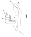
- Fig. 2 is a diagrammatic view of an eddy current probe on the surface of a component.
- the eddy current (EC) probe 12 includes tangential drive coil 30, drive yoke 32, sense coils 34 and sense cores 36 and 37.
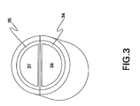
- Fig. 3 illustrates a top view of sense coils 34 and 35. As shown in Fig. 3, sense coils 34 and 35 are wound over sense cores 36 and 37 respectively.
- the eddy current probe is moved in a direction represented by reference numeral 42.
- component 16 has a crack 40 on edge 38.
- Each component of the eddy current probe is described in further detail below.
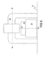
- the tangential drive coil as described earlier is configured to generate a probing field for inducing eddy currents in the component. Some of the eddy currents generated by the tangential drive coil are aligned parallel to an edge 38 of the component. As indicated in FIG. 5, the axis 48 of the tangential drive coil is aligned parallel to a surface 14 of the component 16.
- the tangential drive coil 30 is wound on drive yoke 32.
- the tangential drive coil is formed of a copper winding having 40 turns.
- the copper wire used is American Wire Gauge (AWG) 42 gauge and is 3 mils diameter.
- the drive yoke is formed from a ferrite material.
- Sense coils 34 and 35 are configured to sense the eddy currents aligned parallel to the edge of the component. As indicated in FIG. 5, an axis 50 of the sense coils is aligned perpendicular to the surface 14 of the component 16. Each of the sense coils is wound around a respective one of a pair of sense cores 36 and 37
- each of the sense cores includes a ferrite core. In one embodiment, each of the sense coils is a split core differential sense coil. In one embodiment, the sense cores are D-shaped. In a more specific embodiment, each of the sense coils includes a copper winding have 15 turns wound on a D-shaped sense core.
- Fig. 4 is a diagrammatic view of the induced eddy currents. Eddy currents produced by the tangential drive are represented by reference numeral 44.
- the sense coils 34 and 35 are differentially arranged and oriented symmetric to the edge 38 of surface 14. These sense coils senses a portion of the eddy current which are aligned parallel to the edges. The portion of the eddy currents that are aligned parallel to the edge 38 are collectively represented by reference numeral 46.
- Fig. 5 is a side view of one embodiment of the eddy current probe. As shown in the figure, the axis of the tangential drive coil 48 is aligned parallel to a surface 14 of the component 16. The axis 50 of the sense coils is aligned perpendicular to the surface 14.
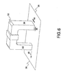
- Fig. 6 is a block diagram illustrating the alignment of the drive yoke with respect to an edge 38 of the surface.
- the drive yoke 32 comprises a pair of legs 52 and 54 which are aligned perpendicular to the edge of the surface as shown by reference numeral 55.
- a relative permeability of the drive yoke is between 1000 and 2000.
- the drive yoke is U shaped.
- the drive yoke is C shaped.
- the parallel orientation of eddy currents is based on the aspect ratio of the cross section and the shapes of the legs.
- the width of the legs 58 is greater than the length 56 of the legs. In a more specific embodiment, the width of the legs is larger than twice the length of the legs.
- the parallel direction of eddy current flow results in a reduced response from the edges of the component, while still retaining a high flaw detectability near the component edges.
- the eddy current probe offers a higher degree of robustness to the component edges under conditions of small probe misalignments.
- the eddy current probe as described above also provides improved reliability for flaw detection at the component edges by reduced edge response
- the eddy current probe as described above uses the tangential drive coil to orient the eddy currents parallel to an edge of the component and hence reduces the edge sensitivity while retaining flaw detection capabilities.
- the direction of the eddy currents provides two significant advantages including reduced edge sensitivity (since the eddy currents near the edges do not get distorted due to the component edge) and robustness towards probe misalignments.
- the eddy current probe also provides higher signal-to-noise ratios for inspection near the component edge.
- the drive yoke and coil provide highly concentrated and aligned eddy currents, which leads to high sensitivity to small cracks.
Landscapes
- Chemical & Material Sciences (AREA)
- Chemical Kinetics & Catalysis (AREA)
- Electrochemistry (AREA)
- Physics & Mathematics (AREA)
- Health & Medical Sciences (AREA)
- Life Sciences & Earth Sciences (AREA)
- Analytical Chemistry (AREA)
- Biochemistry (AREA)
- General Health & Medical Sciences (AREA)
- General Physics & Mathematics (AREA)
- Immunology (AREA)
- Pathology (AREA)
- Investigating Or Analyzing Materials By The Use Of Magnetic Means (AREA)
Abstract
Description
- The invention relates generally to inspection systems and more specifically to a method and system for inspection using eddy current (EC) probes.
- Eddy currents are generally useful for providing a measurable parameter indicative of flaws in the surface and sub-surface of component. Eddy currents are typically affected by changes in the material properties such as electrical conductivity, magnetic permeability, presence of discontinuity, etc. Flaws in the component, such as microscopic hair-line cracks or pits, affect the localized resistance of the material. Flaws in a component usually cause localized variations in the eddy currents in the material. Accordingly, a component can be inspected for flaws by inducing eddy currents in the component and measuring the changes on the eddy currents.
- Eddy current probes detect flaws in a component by sensing perturbations in eddy currents. These probes typically have coils operated at high frequency alternating currents that produce an alternating magnetic field into the component being inspected. The magnetic field induces eddy currents in the component. The strength of the eddy currents depends on the local resistivity of the component, which is affected by the presence of flaws in the component. These eddy currents create a magnetic field that varies in intensity with the distribution of the eddy currents on the component.
- The magnetic field created by the eddy currents induces a voltage in a sense coil. The voltage is displayed as a signal which represents the material property of the component.
- Inspection of engineering components and structures frequently utilize long probe holders with miniature differential eddy current probes. One advantage of using differential probes is the reduced sensitivity to the edge, when oriented symmetric to the edge. However, in practice, one does not always encounter a perfectly straight edge. In addition, small probe misalignments may also exist due to the probe fixtures.
- Such conditions result in significant edge signals and hence a lower inspection reliability. Currently, edge signals are suppressed using a variety of techniques such as butting with additional material to provide a continuous inspection surface, using auxiliary probes and ferrite shields to focus the electromagnetic field, post-processing with image processing techniques to eliminate the edge signals. Such techniques, however, provide an incremental improvement in the elimination of the edge signal.
- Thus, there is a need for a method and system that provides improved suppression of edge signals and detection of edge flaws in various components.
- Briefly, according to one aspect of the invention, an eddy current (EC) probe for inspecting a component is provided. The EC probe includes a tangential drive coil configured to generate a probing field for inducing eddy currents in the component. The axis of this drive coil is aligned parallel to the surface of the component. A portion of the eddy currents generated is aligned parallel to an edge of the component. The EC probes further include a pair of sense coils with an axis of the sense coils aligned perpendicular to the surface of the component. The sense coils are configured to sense the eddy currents aligned parallel to the edge of the component.
- In another embodiment of the invention, a method for inspecting a component is provided. The method includes exciting a drive coil to generate a magnetic field, where an axis of the drive coil is aligned parallel to a surface of the component, and where the magnetic field induces eddy currents in the component. A portion of the generated eddy currents are oriented parallel to an edge of the component. The method further includes sensing the portion of the eddy currents using a pair of sense coils, where an axis of the sense coils is aligned perpendicular to the surface of the component.
- In an alternate embodiment of the invention, a system for inspecting a component is provided. The system includes an eddy current (EC) probe and a control unit. The EC probes include a tangential drive coil configured to generate a probing field for inducing eddy currents in the component. A portion of the eddy currents is aligned parallel to an edge of the component and an axis of the tangential drive coil is aligned parallel to a surface of the component. The EC probe further includes a pair of sense coils, where an axis of the sense coils is aligned perpendicular to the surface of the component, and the sense coils are configured to sense the portion of the eddy currents aligned parallel to the edge of the component. The control unit is coupled to the EC probe and is configured for controlling a motion of the probe.
- The invention will now be described in greater detail, by way of example, with reference to the drawings, in which:-
- FIG. 1 is a block diagram of an eddy current probe inspection system to which embodiments of the present invention are applicable;
- FIG. 2 is a diagrammatic view of an eddy current probe on the surface of a component;
- FIG.3 is a top view of one embodiment of a split-differential pair of sense coils;
- FIG. 4 is a diagrammatic view of a parallel alignment of the eddy currents;
- FIG. 5 is a side view of one embodiment of an eddy current probe; and
- FIG. 6 is a block diagram illustrating the alignment of the drive yoke with respect to the edge of the component.
- FIG. 1 is a block diagram of an embodiment of an
inspection system 10. The inspection system includes an eddycurrent probe 12 that is adapted to induce and senseeddy currents 18 on asurface 14 of acomponent 16. For the configuration depicted in FIG. 1, thecomponent 16 is mounted onsupport 20. The invention is not limited to any specific component, and examples of the component include a turbine blade, turbine disc, bolt holes, etc. In addition, for some applications, thecomponent 16 is not mounted on a support. - The eddy current probe includes a drive coil (not shown in FIG. 1) that is configured for carrying AC current from a
power supply 28. The AC current from the power supply flows through the drive coil and generates a magnetic field surrounding the coil. The magnetic flux from the drive coil generateseddy currents 18 on thesurface 14 and in the vicinity of the probe. - The eddy
current probe 12 also has sense coils (not shown in FIG. 1) and is sensitive to theeddy currents 18 on the surface of the component being inspected. The eddy current induces a potential difference across the sense coil, thereby generating signal which is used for analyzing the material properties. Magnetic flux generated by the eddy currents induces voltage in the sense coil. The drive coil and the sense coils are described in more detail with reference to Fig. 2. - Continuing with Fig. 1, the
probe 12 may be attached to an automatic scanner (not shown), which precisely positions the probe at the surface of a component being inspected. As the eddy current probe moves from one surface location to another, eddy current measurements are made at each location and analyzed by theprocessing unit 24. -
Processing unit 24 is coupled to the eddycurrent probe 12 and adapted to detect the effects from the surface eddy currents on the current in the sense coils. The eddy current data from the processing circuit is provided to an eddycurrent display 26 or other display devices at which the eddy current data is correlated and evaluated to the surface locations at which that data was obtained. - The induced voltage of the sense coils in the eddy
current probe 12 provides information about the surface of the component being inspected such as an abrupt change in eddy current distribution at different locations on the component, which may indicate a presence of a flaw. The signals from the sense coils also provide information regarding the change in the material property of the component. - The processing unit generates information, in the form of reports, display images and/or graphs that show the locations on the surface of the component. The information may be further analyzed to detect and locate the flaw in the component.
- Fig. 2 is a diagrammatic view of an eddy current probe on the surface of a component. The eddy current (EC)
probe 12 includestangential drive coil 30,drive yoke 32, sense coils 34 andsense cores sense cores - Continuing with Fig.2, the eddy current probe is moved in a direction represented by
reference numeral 42. In the illustrated embodiment,component 16 has acrack 40 onedge 38. Each component of the eddy current probe is described in further detail below. - The tangential drive coil as described earlier, is configured to generate a probing field for inducing eddy currents in the component. Some of the eddy currents generated by the tangential drive coil are aligned parallel to an
edge 38 of the component. As indicated in FIG. 5, theaxis 48 of the tangential drive coil is aligned parallel to asurface 14 of thecomponent 16. - Continuing with Fig.2, the
tangential drive coil 30 is wound ondrive yoke 32. In one embodiment, the tangential drive coil is formed of a copper winding having 40 turns. For one exemplary embodiment, the copper wire used is American Wire Gauge (AWG) 42 gauge and is 3 mils diameter. In one embodiment, the drive yoke is formed from a ferrite material. - Sense coils 34 and 35 are configured to sense the eddy currents aligned parallel to the edge of the component. As indicated in FIG. 5, an
axis 50 of the sense coils is aligned perpendicular to thesurface 14 of thecomponent 16. Each of the sense coils is wound around a respective one of a pair ofsense cores - In one embodiment, each of the sense cores includes a ferrite core. In one embodiment, each of the sense coils is a split core differential sense coil. In one embodiment, the sense cores are D-shaped. In a more specific embodiment, each of the sense coils includes a copper winding have 15 turns wound on a D-shaped sense core.
- Fig. 4 is a diagrammatic view of the induced eddy currents. Eddy currents produced by the tangential drive are represented by reference numeral 44. The sense coils 34 and 35 are differentially arranged and oriented symmetric to the
edge 38 ofsurface 14. These sense coils senses a portion of the eddy current which are aligned parallel to the edges. The portion of the eddy currents that are aligned parallel to theedge 38 are collectively represented byreference numeral 46. - Fig. 5 is a side view of one embodiment of the eddy current probe. As shown in the figure, the axis of the
tangential drive coil 48 is aligned parallel to asurface 14 of thecomponent 16. Theaxis 50 of the sense coils is aligned perpendicular to thesurface 14. - Fig. 6 is a block diagram illustrating the alignment of the drive yoke with respect to an
edge 38 of the surface. Thedrive yoke 32 comprises a pair oflegs reference numeral 55. In one embodiment, a relative permeability of the drive yoke is between 1000 and 2000. For the embodiment depicted in FIG. 5, the drive yoke is U shaped. In another embodiment, the drive yoke is C shaped. - The parallel orientation of eddy currents is based on the aspect ratio of the cross section and the shapes of the legs. For the embodiment depicted in FIG. 6, the width of the
legs 58 is greater than thelength 56 of the legs. In a more specific embodiment, the width of the legs is larger than twice the length of the legs. - The parallel direction of eddy current flow results in a reduced response from the edges of the component, while still retaining a high flaw detectability near the component edges. In addition, the eddy current probe offers a higher degree of robustness to the component edges under conditions of small probe misalignments. The eddy current probe as described above also provides improved reliability for flaw detection at the component edges by reduced edge response
- The eddy current probe as described above, uses the tangential drive coil to orient the eddy currents parallel to an edge of the component and hence reduces the edge sensitivity while retaining flaw detection capabilities. The direction of the eddy currents provides two significant advantages including reduced edge sensitivity (since the eddy currents near the edges do not get distorted due to the component edge) and robustness towards probe misalignments.
- The eddy current probe also provides higher signal-to-noise ratios for inspection near the component edge. The drive yoke and coil provide highly concentrated and aligned eddy currents, which leads to high sensitivity to small cracks.
Claims (10)
- An eddy current (EC) probe (12) for inspecting a component (16), said EC probe comprising:a drive coil (30) configured to generate a probing field for inducing a plurality of eddy currents (18) in the component, a portion (46) of the eddy currents being aligned parallel to an edge (38) of the component, anda pair of sense coils (34,35), wherein an axis of said sense coils (50) is aligned perpendicular to a surface (14) of the component, and wherein said sense coils are configured to sense the portion of the eddy currents aligned parallel to the edge of the component.
- The EC probe of claim 1, further comprising:a drive yoke (32), wherein said drive coil is wound on said drive yoke; wherein said drive yoke comprises a pair of legs (52, 54), wherein the legs are aligned perpendicular to the edge of the surface; anda pair of sense cores (36, 37), wherein each of said sense coils is wound around a respective one of said sense cores; and wherein an axis of said drive coil (48) is aligned parallel to a surface of the component.
- The EC probe of claim 3, wherein the legs have a cross section, and wherein the parallel alignment of eddy currents is based on an aspect ratio of the cross section of the legs and a shape of the legs, wherein a shape of the legs is based on a shape of the edge; and wherein a width (58) of the legs is greater than a length (56) of the legs.
- The EC probe of claim 2, wherein each of said drive yoke and said sense cores comprises a ferrite core.
- A method for inspecting a component (16), the method comprising:exciting a drive coil (30) to generate a magnetic field and wherein the magnetic field induces a plurality of eddy currents (14) in the component, a portion (46) of the eddy currents being oriented parallel to an edge (38) of the component; andsensing the portion of the eddy currents using a pair of sense coils (34, 35), wherein an axis of the sense coils (50) is aligned perpendicular to a surface (14) of the component.
- The method of claim 10, wherein the component is a turbine blade or a turbine disc.
- The method of claim 10, wherein the component defines at least one bolt hole, wherein said method further comprises positioning the drive coil and sense coils in a vicinity of the bolt hole.
- The method of claim 10, further comprising detecting and locating a defect on the component.
- A system (10) for inspecting a component (16), said system comprising:an eddy current (EC) probe(12) comprising:a drive coil (30) configured to generate a probing field for inducing a plurality of eddy currents (14) in the component, a portion (46) of the eddy currents being aligned parallel to an edge of the component, anda pair of sense coils (34, 35), wherein an axis of said sense coils (50) is aligned perpendicular to the surface of the component, and wherein said sense coils are configured to sense the portion of the eddy currents aligned parallel to the edge of the component; anda control unit (22) coupled to said EC probe and configured for controlling motion of said EC probe.
- The system of claim 16, wherein said eddy current probe further comprises:a drive yoke (32), wherein said drive coil is wound on said drive yoke; wherein said drive yoke comprises a pair of legs (52, 54), wherein the legs are aligned perpendicular to the edge of the component; wherein said drive yoke comprises a pair of legs, wherein the legs are aligned perpendicular to the edge of the component and wherein a width of the legs (58) is greater than a length of the legs (56); anda pair of sense cores (36, 37), wherein each of said sense coils is wound around a respective one of said sense cores, wherein an axis of said drive coil is aligned parallel to a surface of the component.
Applications Claiming Priority (1)
| Application Number | Priority Date | Filing Date | Title |
|---|---|---|---|
| US11/019,343 US7154265B2 (en) | 2004-12-21 | 2004-12-21 | Eddy current probe and inspection method |
Publications (1)
| Publication Number | Publication Date |
|---|---|
| EP1674861A1 true EP1674861A1 (en) | 2006-06-28 |
Family
ID=36051521
Family Applications (1)
| Application Number | Title | Priority Date | Filing Date |
|---|---|---|---|
| EP05257859A Withdrawn EP1674861A1 (en) | 2004-12-21 | 2005-12-20 | Eddy current probe and inspection method comprising a pair of sense coils |
Country Status (3)
| Country | Link |
|---|---|
| US (1) | US7154265B2 (en) |
| EP (1) | EP1674861A1 (en) |
| JP (1) | JP2006177952A (en) |
Families Citing this family (12)
| Publication number | Priority date | Publication date | Assignee | Title |
|---|---|---|---|---|
| JP4234761B2 (en) * | 2006-11-21 | 2009-03-04 | 慶一 野々垣 | Eddy current flaw detection method and apparatus |
| US7817845B2 (en) * | 2006-12-29 | 2010-10-19 | General Electric Company | Multi-frequency image processing for inspecting parts having complex geometric shapes |
| US7876093B2 (en) * | 2007-12-06 | 2011-01-25 | General Electric Company | Eddy current inspection device, proximity probe and method for assembling an eddy current inspection device |
| US20120043962A1 (en) * | 2010-08-20 | 2012-02-23 | Changting Wang | Method and apparatus for eddy current inspection of case-hardended metal components |
| WO2015190414A1 (en) * | 2014-06-12 | 2015-12-17 | コニカミノルタ株式会社 | Nondestructive inspection device |
| US10073058B2 (en) | 2015-02-11 | 2018-09-11 | Structural Integrity Associates | Dynamic pulsed eddy current probe |
| US10895555B2 (en) | 2015-03-30 | 2021-01-19 | Structural Integrity Associates, Inc. | System for in-line inspection using a dynamic pulsed eddy current probe and method thereof |
| CN106198723B (en) * | 2016-07-07 | 2023-07-28 | 江苏方天电力技术有限公司 | A detection device and method for cracks on the inner wall of a bolt heating hole |
| US10260854B2 (en) | 2016-12-07 | 2019-04-16 | Probe Technology Services, Inc. | Pulsed eddy current casing inspection tool |
| CN109946372A (en) * | 2019-04-09 | 2019-06-28 | 鞍钢股份有限公司 | Eddy current probe for flaw detection of steel surface |
| CN110794030A (en) * | 2019-10-18 | 2020-02-14 | 中车青岛四方机车车辆股份有限公司 | A non-directional weld eddy current detection probe and detection device |
| US12298274B2 (en) | 2022-09-05 | 2025-05-13 | General Electric Company | Flexible sensor assembly |
Citations (7)
| Publication number | Priority date | Publication date | Assignee | Title |
|---|---|---|---|---|
| GB631987A (en) * | 1947-07-25 | 1949-11-14 | Superheater Co Ltd | Improvements in and relating to apparatus for testing materials by magnetic or electrical analysis |
| US4495466A (en) * | 1982-04-08 | 1985-01-22 | The United States Of America As Represented By The Secretary Of The Air Force | Eddy current test probe with circumferential Segments and method of testing material surrounding fastener holes |
| US5399968A (en) * | 1992-01-31 | 1995-03-21 | Northrop Grumman Corporation | Eddy current probe having body of high permeability supporting drive coil and plural sensors |
| US5446382A (en) * | 1993-06-23 | 1995-08-29 | The Babcock & Wilcox Company | Eddy current probe having one yoke within another yoke for increased inspection depth, sensitivity and discrimination |
| JP2000131287A (en) * | 1998-10-23 | 2000-05-12 | Japan Science & Technology Corp | Method and apparatus for flaw detection by magnetic measurement |
| EP1111379A1 (en) * | 1999-12-22 | 2001-06-27 | General Electric Company | Eddy current probe with foil sensor mounted on flexible probe tip and method of use |
| US20030070492A1 (en) * | 2001-10-17 | 2003-04-17 | Accentus Plc. | Detection of rolling contact fatigue |
Family Cites Families (8)
| Publication number | Priority date | Publication date | Assignee | Title |
|---|---|---|---|---|
| US3609528A (en) | 1969-04-21 | 1971-09-28 | Computer Test Corp | Noise pulse cancellation system formed by a pair of transformers |
| JPS62115357A (en) * | 1985-11-14 | 1987-05-27 | Toshiba Corp | Defect inspection device |
| JP2976672B2 (en) | 1992-02-19 | 1999-11-10 | 日本鋼管株式会社 | Edge crack and perforation detection device |
| US5239230A (en) | 1992-03-27 | 1993-08-24 | General Electric Company | High brightness discharge light source |
| JPH07311179A (en) | 1994-05-19 | 1995-11-28 | Hitachi Cable Ltd | Eddy current flaw detection coil |
| EP0819944A1 (en) * | 1996-07-16 | 1998-01-21 | Lucent Technologies Inc. | Eddy current sensor |
| JP4659194B2 (en) * | 1999-09-22 | 2011-03-30 | ゼネラル・エレクトリック・カンパニイ | Eddy current calibration standard |
| JP4582564B2 (en) | 2001-06-25 | 2010-11-17 | ソニーマニュファクチュアリングシステムズ株式会社 | Magnetic flux measuring device |
-
2004
- 2004-12-21 US US11/019,343 patent/US7154265B2/en not_active Expired - Fee Related
-
2005
- 2005-12-16 JP JP2005362697A patent/JP2006177952A/en active Pending
- 2005-12-20 EP EP05257859A patent/EP1674861A1/en not_active Withdrawn
Patent Citations (7)
| Publication number | Priority date | Publication date | Assignee | Title |
|---|---|---|---|---|
| GB631987A (en) * | 1947-07-25 | 1949-11-14 | Superheater Co Ltd | Improvements in and relating to apparatus for testing materials by magnetic or electrical analysis |
| US4495466A (en) * | 1982-04-08 | 1985-01-22 | The United States Of America As Represented By The Secretary Of The Air Force | Eddy current test probe with circumferential Segments and method of testing material surrounding fastener holes |
| US5399968A (en) * | 1992-01-31 | 1995-03-21 | Northrop Grumman Corporation | Eddy current probe having body of high permeability supporting drive coil and plural sensors |
| US5446382A (en) * | 1993-06-23 | 1995-08-29 | The Babcock & Wilcox Company | Eddy current probe having one yoke within another yoke for increased inspection depth, sensitivity and discrimination |
| JP2000131287A (en) * | 1998-10-23 | 2000-05-12 | Japan Science & Technology Corp | Method and apparatus for flaw detection by magnetic measurement |
| EP1111379A1 (en) * | 1999-12-22 | 2001-06-27 | General Electric Company | Eddy current probe with foil sensor mounted on flexible probe tip and method of use |
| US20030070492A1 (en) * | 2001-10-17 | 2003-04-17 | Accentus Plc. | Detection of rolling contact fatigue |
Non-Patent Citations (1)
| Title |
|---|
| PATENT ABSTRACTS OF JAPAN vol. 2000, no. 08 6 October 2000 (2000-10-06) * |
Also Published As
| Publication number | Publication date |
|---|---|
| JP2006177952A (en) | 2006-07-06 |
| US7154265B2 (en) | 2006-12-26 |
| US20060132124A1 (en) | 2006-06-22 |
Similar Documents
| Publication | Publication Date | Title |
|---|---|---|
| CN102759567A (en) | Eddy current testing recognition and evaluation method for defects of inner wall and outer wall of steel pipe under direct current magnetization | |
| US7154265B2 (en) | Eddy current probe and inspection method | |
| US11428668B2 (en) | Probe for eddy current non-destructive testing | |
| US8717012B2 (en) | Eddy current probe for surface and sub-surface inspection | |
| EP2746761A1 (en) | Method for magnetic flaw detection and magnetic flaw detector | |
| JP5851783B2 (en) | Eddy current testing probe | |
| JP2011047736A (en) | Method of inspecting austenite-based stainless steel welding section | |
| JP2008032575A (en) | Eddy current measuring probe and flaw detector using the same | |
| JP4117645B2 (en) | Eddy current testing probe and eddy current testing equipment for magnetic materials | |
| JP5638544B2 (en) | Eddy current testing probe | |
| JP3572452B2 (en) | Eddy current probe | |
| JP6601226B2 (en) | Magnetic flux leakage flaw detector | |
| KR101988887B1 (en) | Lissajour curve display apparatus using magnetic sensor array | |
| JP6378554B2 (en) | Nondestructive inspection apparatus and nondestructive inspection method | |
| JP5290020B2 (en) | Eddy current flaw detection method and eddy current flaw detection sensor | |
| JP3942165B2 (en) | Eddy current testing probe | |
| Yamada et al. | Application of ECT technique for inspection of bare PCB | |
| JP2014066688A (en) | Eddy current flaw detection probe, and eddy current flaw detection device | |
| JPH09507294A (en) | Method and apparatus for magnetically testing metal products | |
| JP2016133459A (en) | Eddy current testing probe, Eddy current testing equipment | |
| JPH07113788A (en) | Eddy current flaw detection probe coil | |
| JP2021001813A (en) | Nondestructive inspection magnetic sensor and nondestructive inspection device | |
| JP2006053053A (en) | Eddy current flaw detection probe device | |
| RU103926U1 (en) | ELECTROMAGNETIC CONVERTER TO DEFECTOSCOPE | |
| JP2006010665A (en) | Eddy current flaw detection method and eddy current flaw probe realizing deep eddy current penetration |
Legal Events
| Date | Code | Title | Description |
|---|---|---|---|
| PUAI | Public reference made under article 153(3) epc to a published international application that has entered the european phase |
Free format text: ORIGINAL CODE: 0009012 |
|
| AK | Designated contracting states |
Kind code of ref document: A1 Designated state(s): AT BE BG CH CY CZ DE DK EE ES FI FR GB GR HU IE IS IT LI LT LU LV MC NL PL PT RO SE SI SK TR |
|
| AX | Request for extension of the european patent |
Extension state: AL BA HR MK YU |
|
| 17P | Request for examination filed |
Effective date: 20061228 |
|
| 17Q | First examination report despatched |
Effective date: 20070206 |
|
| AKX | Designation fees paid |
Designated state(s): DE FR GB |
|
| STAA | Information on the status of an ep patent application or granted ep patent |
Free format text: STATUS: THE APPLICATION IS DEEMED TO BE WITHDRAWN |
|
| 18D | Application deemed to be withdrawn |
Effective date: 20110701 |