EP1674751A1 - Ausrückvorrichtung - Google Patents
Ausrückvorrichtung Download PDFInfo
- Publication number
- EP1674751A1 EP1674751A1 EP05024493A EP05024493A EP1674751A1 EP 1674751 A1 EP1674751 A1 EP 1674751A1 EP 05024493 A EP05024493 A EP 05024493A EP 05024493 A EP05024493 A EP 05024493A EP 1674751 A1 EP1674751 A1 EP 1674751A1
- Authority
- EP
- European Patent Office
- Prior art keywords
- housing
- release device
- actuating lever
- release
- different
- Prior art date
- Legal status (The legal status is an assumption and is not a legal conclusion. Google has not performed a legal analysis and makes no representation as to the accuracy of the status listed.)
- Granted
Links
- 238000009434 installation Methods 0.000 claims description 16
- 230000002787 reinforcement Effects 0.000 claims description 12
- 230000003287 optical effect Effects 0.000 claims description 8
- 239000004033 plastic Substances 0.000 claims description 6
- 229920003023 plastic Polymers 0.000 claims description 6
- 238000000034 method Methods 0.000 claims description 4
- 230000008569 process Effects 0.000 claims description 4
- 238000004519 manufacturing process Methods 0.000 claims description 3
- 230000000007 visual effect Effects 0.000 claims description 3
- 229910000831 Steel Inorganic materials 0.000 claims description 2
- 239000011248 coating agent Substances 0.000 claims description 2
- 238000000576 coating method Methods 0.000 claims description 2
- 238000005520 cutting process Methods 0.000 claims description 2
- 230000007246 mechanism Effects 0.000 claims description 2
- 239000010959 steel Substances 0.000 claims description 2
- 238000002347 injection Methods 0.000 claims 1
- 239000007924 injection Substances 0.000 claims 1
- 230000005540 biological transmission Effects 0.000 description 7
- 238000013459 approach Methods 0.000 description 5
- 230000008901 benefit Effects 0.000 description 3
- 230000013011 mating Effects 0.000 description 3
- 230000008859 change Effects 0.000 description 2
- 238000002485 combustion reaction Methods 0.000 description 2
- 239000011152 fibreglass Substances 0.000 description 2
- 230000009467 reduction Effects 0.000 description 2
- 241000833016 Ballus Species 0.000 description 1
- 229920000271 Kevlar® Polymers 0.000 description 1
- 238000010276 construction Methods 0.000 description 1
- 230000001419 dependent effect Effects 0.000 description 1
- 238000006073 displacement reaction Methods 0.000 description 1
- 238000003780 insertion Methods 0.000 description 1
- 230000037431 insertion Effects 0.000 description 1
- 238000005304 joining Methods 0.000 description 1
- 239000004761 kevlar Substances 0.000 description 1
- 238000002372 labelling Methods 0.000 description 1
- 230000009347 mechanical transmission Effects 0.000 description 1
- 239000007921 spray Substances 0.000 description 1
- 238000003860 storage Methods 0.000 description 1
- 238000011179 visual inspection Methods 0.000 description 1
Images


Classifications
-
- F—MECHANICAL ENGINEERING; LIGHTING; HEATING; WEAPONS; BLASTING
- F16—ENGINEERING ELEMENTS AND UNITS; GENERAL MEASURES FOR PRODUCING AND MAINTAINING EFFECTIVE FUNCTIONING OF MACHINES OR INSTALLATIONS; THERMAL INSULATION IN GENERAL
- F16D—COUPLINGS FOR TRANSMITTING ROTATION; CLUTCHES; BRAKES
- F16D23/00—Details of mechanically-actuated clutches not specific for one distinct type
- F16D23/12—Mechanical clutch-actuating mechanisms arranged outside the clutch as such
-
- F—MECHANICAL ENGINEERING; LIGHTING; HEATING; WEAPONS; BLASTING
- F16—ENGINEERING ELEMENTS AND UNITS; GENERAL MEASURES FOR PRODUCING AND MAINTAINING EFFECTIVE FUNCTIONING OF MACHINES OR INSTALLATIONS; THERMAL INSULATION IN GENERAL
- F16D—COUPLINGS FOR TRANSMITTING ROTATION; CLUTCHES; BRAKES
- F16D23/00—Details of mechanically-actuated clutches not specific for one distinct type
- F16D23/12—Mechanical clutch-actuating mechanisms arranged outside the clutch as such
- F16D23/14—Clutch-actuating sleeves or bearings; Actuating members directly connected to clutch-actuating sleeves or bearings
- F16D2023/141—Clutch-actuating sleeves or bearings; Actuating members directly connected to clutch-actuating sleeves or bearings characterised by using a fork; Details of forks
Definitions
- the invention relates to a release device for a used in vehicles with manual mechanical transmission shift clutch.
- the disengaging device comprises a drive shaft spaced spaced enclosing, hollow cylindrical shaped housing which is axially displaceable upon actuation of the release device.
- the housing On the side facing the gearshift clutch, the housing is connected to a release bearing.
- the housing Opposite to the release bearing, the housing is in operative connection with an actuating lever, wherein the housing is connected in a form-fitting, play-related manner with the actuating lever.
- the housing of the disengaging takes over the function of a support member or a transmission member which separates upon actuation of the disengaging device in conjunction with the operating lever and the release bearing on the gearshift clutch power flow between the engine and the gearbox, thus enabling a gear change of the gearbox.
- the release bearing can be captive captive with the housing.
- This release device comprises a release bearing whose inner ring is provided with a radially outwardly extended flange, whereby the inner ring of the release bearing engages against rotation in an actuating lever designed as a release fork.
- an actuating lever designed as a release fork.
- additional retaining elements are used for the connection of the release fork with the extended flange portion of the inner ring separate.
- the disengaging device comprises a release bearing, which encloses a retaining plate and a spring washer in connection with the outer securing means for securing against loss on the housing.
- the spring washer on a tab, in the recess a hook of the washer locked.
- the retaining element surrounds the annular flange of the housing, so that at different temperature expansion coefficients between the directly interacting components, the risk of distortion arises.
- the FR 2 304 826 A1 shows as a release device also an axially displaceable housing which communicates with a release bearing.
- a release bearing For the loss-secured arrangement of the release bearing of the annular flange of the housing is enclosed by a sleeve which extends on one side axially over the release bearing and positioned by means of a radially inboard Bordes the release bearing.
- the invention is based on the problem to provide a precompletable release device that allows different heights without additional parts for use in various manual transmissions.
- the actuating lever forms a receptacle in which the housing is fixed against rotation in at least two different installation positions.
- the different installation positions allow different heights, i. E. a height compensation of the release device.
- the housing has for each installation position in each case two offset by 90 °, arranged in pairs contact surfaces, via which the housing can be supported on the actuating lever.
- the release device according to the invention can be used for maintaining the components, housing and operating lever for different vehicles.
- the height compensation of the release device according to the invention allows the installation of a device of identical construction in vehicles whose transmission and / or engine configuration differs.
- the height compensation can for example be such that the length of the different contact surfaces is adapted to the installation situation of at least two gearbox variants with which an engine of the vehicle can be combined.
- an economic advantage arises because the operating levers and housings are used for various sizes of manual transmissions or motors.
- the invention results in a desired reduction in component size, since identical release mechanisms for different drive concepts, that is to say design, are used.
- H. Various assignments of manual transmissions can be used with internal combustion engines. The reduction of difference parts reduces the logistical effort, simplifies the storage and brings a cost advantage.
- a preferred embodiment of the invention comprises a release device, the housing of each installation position includes corresponding contact surfaces, which cooperate in the installed state with the actuating lever.
- the contact surfaces are formed as axially projecting lugs, which allow an unhindered actuating movement of the actuating lever relative to the housing during the actuation of the release device.
- the desired different height of the release device according to the invention by 90 ° twisted insertion of the housing in the operating lever.
- a preferred embodiment of the invention includes a housing with spherically shaped lugs on the contact surfaces.
- the invention also includes frontally straight formed projections of the housing on the contact surfaces, which cooperate with the actuating lever.
- the housing is made of plastic, including in particular a glass fiber reinforced plastic is suitable.
- the structure of the housing includes integrally formed contact surfaces, so that in a manufacturing process, a spray process, the housing is inexpensive to produce.
- the housing with a reinforcement.
- a reinforcement for example, a sleeve-like shaped, the outer surface of the housing enclosing reinforcement, which also includes the axially projecting projections enclosing contact surfaces.
- a secured arrangement of the reinforcement can be made for example by means of a snap connection, in which a protruding nubs of the housing snapped in the installed position in a corresponding recess of the reinforcement.
- the invention also includes, if necessary, the projections of the contact surfaces of the housing and / or the mating surfaces of the actuating lever in the area to coat the contact zone. For this purpose, it is advisable to provide a wear-reducing and / or a friction-reducing coating in order to reduce the wear in the region of the contact surface between the housing and the actuating lever. This simultaneously noise-avoiding measure advantageously increases the life of the release device.
- the invention includes that a reinforcement is made as a multi-layer directly together with the production of the housing in a Mehrstoffspritzmaschinen so that a positive and / or cohesive connection of the two components is ensured.
- the housing has flattened areas on the lateral surface.
- the mutually parallel flats engage in the installed position positively and with play in a corresponding with the lateral surface of the housing receiving the actuating lever.
- the housing may include two offset by 90 °, arranged in pairs bearing surfaces whose flats have different key widths.
- An advantageous embodiment of the housing provides to provide this with two different key widths in the region of the lateral surface.
- This structure simplifies a position-oriented assignment when the housing is mounted in the actuating lever, in that each wrench size corresponds to a defined mounting position, ie, alignment of the housing relative to the actuating lever.
- the different key widths ensure, in particular, an automated, process-reliable installation of the release device.
- each installation situation is provided with a color coding between the housing and the actuating lever.
- a color coding between the housing and the actuating lever.
- an applied barcode is provided as an optical display in the area of the contact surfaces.
- the provided with different barcodes contact surfaces allow for automated assembly that the robot assigns the housing relative to the operating lever position-oriented.
- the release device may further be provided with an optical display between the housing and the operating lever, which is visible only after completion of the release device.
- This measure lends itself, for example, to a mounting device in which the desired overall height is predetermined and in which a color-coded area of the housing becomes visible in a recess of the actuating lever only after assembly has taken place.
- the invention includes recessed or protruding characters, which are preferably arranged in the region of the lateral surface of the housing and which are invisible or readable after installation.
- recessed or protruding characters which are preferably arranged in the region of the lateral surface of the housing and which are invisible or readable after installation.
- a rib-like structure, a font, numeral or letters or a colored marking is suitable.
- an integrally formed on the housing forming a visual display rib on a predetermined breaking point, which in a position match between the housing and the actuating lever requires only a slight increased joining force in order to insert the housing into the corresponding receptacle of the actuating lever.
- a snap connection is provided.
- a fixing cam setting or notching which engages positively in the installed state in a corresponding recess or recess of the actuating lever.
- the release device comprises a housing made of plastic and an actuating lever made of sheet steel. Cost effective to the operating lever is produced without cutting through a deep drawing process. Furthermore, the invention includes an actuating lever, which is made of a high-strength plastic, such as glass fiber reinforced plastic or Kevlar.
- the invention provides that all components of the release device, the housing, the actuating lever and the release bearing are assembled captive regardless of the assignment of these components to achieve different heights to a unit.
- FIG. 1 shows a disengaging device 1 which comprises an actuating lever 2, a housing 3 and a release bearing 4.
- the actuating lever 2 is supported at one end to a stationary bearing point 5.
- a gearshift clutch 6 of which a plate spring is shown, a force acting in the direction of arrow is exerted on the other end of the actuating lever 2, whereby the release bearing 4 also axially displaces in the direction of arrow and thereby breaks a flow of force through the gearshift clutch 6, for example to allow a gear change of the gearbox.
- the housing 3 forms two sublime running contact surfaces 8a, 8b, formed as axially projecting lugs 9a, 9b, which are frontally convex or convex and bear with a largely straight or flat mating surface 10 frictionally against the operating lever 2.
- the housing 3 is positively inserted into a receptacle 11 of the actuating lever 2.
- the housing 3 has two parallel flats 12 a, 12 b, which is inserted into a largely correspondingly shaped receptacle 11 of the actuating lever 2.
- the housing 3 is positively fixed, secured against rotation in the actuating lever 2, wherein at the same time functionally limited displacement of the housing 3 in the longitudinal direction of the actuating lever 2 is possible.
- the assembled to form a unit components of the release device 1 are permanently connected to each other.
- the housing 3 is secured together by means of a snap connection 13 shown in FIGS. 3 and 4 assembled together.
- the snap connection 13 comprises at least one fixing cam 14, which, as shown in FIG. 4, engages behind a wall 15 of the actuating lever 2 in the installed position.
- a correct installation position is reached as soon as a marking 17 applied to the projection 9a is visible and is not obscured by a web 24 of the actuating lever 2 by means of an optical display 16 shown in FIG ,
- FIG. 3 illustrates the structure of the housing 3, which simultaneously serves as a carrier part for the release bearing 4.
- An outer bearing ring 23 of the release bearing 4 is fixed in a torsionally rigid manner on the housing 3.
- an adjusting ring 21 is supported, which is frontally connected to a plate spring of the shift disconnect clutch 6.
- FIGs 5 and 6 show the housing 3 in connection with the release bearing 4 in a perspective. These representations illustrate in particular the constructively differently shaped contact zone 7 marked “h” or “h 1 " on the housing 3 relative to the actuating lever 2, in order to achieve height compensation "S” according to FIG the housing 3 comprises four contact surfaces 8a, 8b; 18a, 18b.
- the advantage of using a lever for two different applications is ensured by two key widths SW 1 and SW 2 .
- the axially projecting lugs 19a, 19b of the contact surfaces 18a, 18b exceed the length of the other axial lugs 9a, 9b of the contact surfaces 8a, 8b.
- the disengaging device 1 can be used with the same component circumference for different manual transmissions and / or internal combustion engines.
- the molded directly on the housing 3 made of plastic bearing surfaces 8a, 8b; 18a, 18b in conjunction with the associated axial lugs 9a, 9b; 19a, 19b ensure a different height or allow height compensation "S".
- the housing 3 according to FIG. 5 has, in the region of the flattening 22a, a tuning rib 25, which in particular serves to prevent incorrect assembly of the housing 3.
- the Abstimmrippe 25 on a predetermined breaking point which shears off after applying an increased press-fit force and thus allows unhindered installation of the housing 3 in both positions.
- the housing 3 according to FIG. 6 has a largely annular reinforcement 26 which, as a separate component, has all the contact surfaces 8a, 8b; 18a, 18b.
- the reinforcement 26 is adapted to the inside of the contour of the lateral surface 27 of the housing 3 and thus positively, non-rotatably connected to the housing 3.
- the opposite to the plastic of the housing 3 having a higher strength armor 26 reduces or avoids wear in the region of the contact zone 7 between the housing 3 and the actuating lever 2.
- the reinforcement 26 has different key widths in the region of the contact surfaces 8a, 8b; 18a, 18b simplified on the automated assembly.
- Housing 3 are always picked up by a tool of the same wrench size and are joined together with the operating lever 2, whereby a faulty assembly is omitted.
- it makes sense to form the between the contact surfaces 8a, 8b adjusting key width "SW 1 " greater than the other key way "SW 2 ", which is established between the contact surfaces 18a, 18b.
- FIG. 7 shows the possible height compensation "S" which is set by the different assignment of the housing 3 relative to the actuating lever 2. This height compensation "S” can be realized by the housing 3 is rotated by 90 ° relative to the operating lever 2 is used.
Landscapes
- Engineering & Computer Science (AREA)
- General Engineering & Computer Science (AREA)
- Mechanical Engineering (AREA)
- Mechanical Operated Clutches (AREA)
- Eye Examination Apparatus (AREA)
- Mechanical Control Devices (AREA)
Abstract
Description
- Die Erfindung betrifft eine Ausrückvorrichtung für eine in Fahrzeugen mit mechanischem Handschaltgetriebe eingesetzte Schalttrennkupplung. Die Ausrückvorrichtung umfasst ein eine Antriebswelle beabstandet umschließendes, hohlzylindrisch gestaltetes Gehäuse, das bei einer Betätigung der Ausrückvorrichtung axial verschiebbar ist. Auf dem zur Schalttrennkupplung gerichteten Seite ist das Gehäuse mit einem Ausrücklager verbunden. Gegenüberliegend zu dem Ausrücklager steht das Gehäuse mit einem Betätigungshebel in einer Wirkverbindung, wobei das Gehäuse formschlüssig, spielbehaftet mit dem Betätigungshebel verbunden ist.
- Das Gehäuse der Ausrückvorrichtung übernimmt die Funktion eines Trägerteils bzw. eines Übertragungsgliedes, das bei einer Betätigung der Ausrückvorrichtung in Verbindung mit dem Betätigungshebel und dem Ausrücklager über die Schalttrennkupplung einen Kraftfluss zwischen der Brennkraftmaschine und dem Schaltgetriebe trennt und damit einen Gangwechsel des Schaltgetriebes ermöglicht. Zur Montagevereinfachung der Ausrückvorrichtung sind Konzepte bekannt, bei denen das Ausrücklager unverlierbar mit dem Gehäuse vorkomplettiert werden kann.
- Aus der DE 76 00 543 U1 ist eine solche Vorrichtung bekannt. Diese Ausrückvorrichtung umfasst ein Ausrücklager, dessen Innenring mit einem radial nach außen verlängerten Flansch versehen ist, wodurch der Innenring des Ausrücklagers drehsicher in einen als Ausrückgabel gestalteten Betätigungshebel eingreift. Für die Verbindung der Ausrückgabel mit dem verlängert ausgebildeten Flanschabschnitt des Innenrings werden separate, zusätzliche Halteelemente eingesetzt. Diese bekannte Maßnahme verkürzt die Montagezeiten und ermöglicht eine weitestgehend automatisierte Montage.
- Die Ausrückvorrichtung gemäß der DE 28 30 249 A1 umfasst ein Ausrücklager, welches zur verliergesicherten Anordnung an dem Gehäuse ein Halteblech sowie eine Federscheibe in Verbindung außenseitiger Befestigungsmittel einschließt. Dazu weist die Federscheibe eine Lasche auf, in deren Aussparung ein Haken der Unterlegscheibe verrastet. Nachteilig umschließt das Halteelement unmittelbar den Ringflansch des Gehäuses, so dass bei unterschiedlichen Temperatur-Ausdehnungskoeffizienten zwischen den unmittelbar zusammenwirkenden Bauteilen die Gefahr einer Verspannung entsteht.
- Die FR 2 304 826 A1 zeigt als Ausrückvorrichtung ebenfalls ein axial verschiebbares Gehäuse, das mit einem Ausrücklager in Verbindung steht. Zur verliergesicherten Anordnung des Ausrücklagers ist der Ringflansch des Gehäuses von einer Hülse umschlossen, die sich einseitig axial über das Ausrücklager erstreckt und mittels eines radial nach innen gerichteten Bordes das Ausrücklager positioniert.
- Der Erfindung liegt die Problemstellung zugrunde, eine vorkomplettierbare Ausrückvorrichtung zu schaffen, die ohne Zusatzteile unterschiedliche Bauhöhen ermöglicht zum Einsatz in verschiedenen Schaltgetrieben.
- Zur Lösung dieser Aufgabe ist bei einer Ausrückvorrichtung der zuvor genannten Bauart erfindungsgemäß vorgesehen, dass der Betätigungshebel eine Aufnahme bildet, in der das Gehäuse in zumindest zwei voneinander abweichenden Einbaupositionen drehfest fixiert ist. Die voneinander abweichenden Einbaupositionen ermöglichen unterschiedliche Bauhöhen, d.h. einen Höhenausgleich der Ausrückvorrichtung. Das Gehäuse weist dazu für jede Einbauposition jeweils zwei um 90° versetzte, paarweise angeordnete Anlageflächen auf, über die sich das Gehäuse an dem Betätigungshebel abstützen kann. Die erfindungsgemäße Ausrückvorrichtung ist bei einer Beibehaltung der Bauteile, Gehäuse und Betätigungshebel für unterschiedliche Fahrzeuge einsetzbar. Vorteilhaft ermöglicht der Höhenausgleich der erfindungsgemäßen Ausrückvorrichtung den Einbau einer baugleichen Vorrichtung in Fahrzeuge deren Getriebe-und oder/oder Motorkonfiguration sich unterscheidet.
- Der Höhenausgleich kann beispielsweise so erfolgen, dass die Länge der unterschiedlichen Anlageflächen an die Einbausituation von zumindest zwei Schaltgetriebe-Varianten angepasst ist, mit denen ein Motor des Fahrzeugs kombinierbar ist. Im Vergleich zu bisherigen Lösungen stellt sich ein wirtschaftlicher Vorteil ein, da die Betätigungshebel und Gehäuse für verschiedene Baugrößen von Schaltgetrieben oder Motoren Verwendung finden. Für Fahrzeughersteller stellt sich durch die Erfindung eine gewünschte Bauteilverringerung ein, da vom Aufbau identische Ausrückvorrichtungen für unterschiedliche Antriebskonzepte, d. h. verschiedene Zuordnungen von Schaltgetrieben mit Brennkraftmaschinen einsetzbar sind. Die Verringerung von Unterschiedsteilen reduziert den logistischen Aufwand, vereinfacht die Lagerhaltung und bewirkt einen Kostenvorteil.
- Vorteilhafte Ausgestaltungen der Erfindung sind Gegenstand der abhängigen Ansprüche 2 bis 23.
- Eine bevorzugte Ausgestaltung der Erfindung umfasst eine Ausrückvorrichtung, deren Gehäuse jeder Einbauposition entsprechende Anlageflächen einschließt, die im eingebauten Zustand mit dem Betätigungshebel zusammenwirken. Dabei sind die Anlageflächen als axial vorstehende Ansätze ausgebildet, die bei der Betätigung der Ausrückvorrichtung eine ungehinderte Stellbewegung des Betätigungshebels gegenüber dem Gehäuse ermöglichen. Die gewünschte unterschiedliche Bauhöhe der Ausrückvorrichtung ist erfindungsgemäß durch um 90° verdrehtes Einsetzen des Gehäuses in den Betätigungshebel.
- Eine bevorzugte Ausgestaltung der Erfindung schließt ein Gehäuse mit ballig gestalteten Ansätzen an der Anlageflächen ein. Die auch als Ballus zu bezeichnenden Ansätze bilden mit zugehörigen Gegenflächen des Betätigungshebels eine Kontaktzone. Alternativ dazu schließt die Erfindung ebenfalls stirnseitig gerade ausgebildete Ansätze des Gehäuses an den Anlageflächen ein, die mit dem Betätigungshebel zusammenwirken.
- Bevorzugt ist das Gehäuse aus Kunststoff hergestellt, wozu sich insbesondere ein glasfaserverstärkter Kunststoff eignet. Der Aufbau des Gehäuses schließt dabei einstückig angeformte Anlageflächen ein, so dass in einem Herstellprozeß, einem Spritzverfahren, das Gehäuse kostengünstig herstellbar ist.
- Zur Erzielung einer hochfesten, verschleißoptimierten Gestaltung der Anlageflächen bietet es sich weiterhin an, das Gehäuse mit einer Armierung zu versehen. Dazu eignet sich beispielsweise eine hülsenartig geformte, die Mantelfläche des Gehäuses umschließende Armierung, die gleichzeitig die axial vorstehenden Ansätze einschließende Anlageflächen umfasst. Eine verliergesicherte Anordnung der Armierung kann dabei beispielsweise mittels einer Schnappverbindung hergestellt werden, bei der ein vorstehender Noppen des Gehäuses in der Einbaulage in eine korrespondierende Ausnehmung der Armierung verschnappt.
- Die Erfindung schließt bei Bedarf außerdem ein, die Ansätze der Anlageflächen des Gehäuses und / oder die Gegenflächen des Betätigungshebels im Bereich der Kontaktzone zu beschichten. Dazu bietet es sich an, eine verschleißmindernde und / oder eine reibungsmindernde Beschichtung vorzusehen, um den Verschleiß im Bereich der Kontaktfläche zwischen dem Gehäuse und dem Betätigungshebel zu verringern. Diese gleichzeitig eine Geräuschentwicklung vermeidende Maßnahme erhöht vorteilhaft die Lebensdauer der Ausrückvorrichtung.
- Weiterhin schließt die Erfindung ein, dass eine Armierung als Mehrstoffschicht direkt zusammen mit der Herstellung des Gehäuses in einem Mehrstoffspritzverfahren so gefertigt wird, damit eine form- und / oder stoffschlüssige Verbindung beider Bauteile gewährleistet ist.
- Zur Erzielung einer für die Funktion der Ausrückvorrichtung erforderlichen verdrehgesicherten Anordnung des Gehäuses gegenüber dem Betätigungshebel weist das Gehäuse an der Mantelfläche Abflachungen auf. Die parallel zueinander angeordneten Abflachungen greifen in der Einbaulage formschlüssig und spielbehaftet in eine mit der Mantelfläche des Gehäuses korrespondierenden Aufnahme des Betätigungshebels ein. Diese Anordnung ermöglicht eine ungehinderte winkelbegrenzte Stellbewegung des Betätigungshebels gegenüber dem Gehäuse bei einer Betätigung der Ausrückvorrichtung.
- Weiterhin kann gemäß der Erfindung das Gehäuse zwei um 90° versetzte, paarweise angeordnete Anlageflächen einschließen, deren Abflachungen unterschiedliche Schlüsselweiten aufweisen.
- Eine vorteilhafte Ausgestaltung des Gehäuses sieht vor, dieses mit zwei unterschiedlichen Schlüsselweiten im Bereich der Mantelfläche zu versehen. Dieser Aufbau vereinfacht eine lageorientierte Zuordnung bei einer Montage des Gehäuses in den Betätigungshebel, indem jede Schlüsselweite einer definierten Einbaulage, d. h. Ausrichtung des Gehäuses gegenüber dem Betätigungshebel entspricht. Die unterschiedlichen Schlüsselweiten gewährleisten insbesondere eine automatisierte, prozesssichere Montage der Ausrückvorrichtung.
- Als eine ergänzende oder alternative Maßnahme eine Fehlmontage zwischen dem Gehäuse und dem Betätigungshebel zu verhindern ist erfindungsgemäß eine optische Anzeige vorgesehen. Vorteilhaft ist dazu jeder Einbausituation eine farbliche Kennzeichnung zwischen dem Gehäuse und dem Betätigungshebel vorgesehen. Dadurch ist nach erfolgter Montage mittels Sichtkontrolle der Einbau kontrollierbar. Andererseits vereinfacht beispielsweise eine unterschiedliche farbige Kennzeichnung der jeweiligen Anlageflächen eine Montage mittels Roboter, indem dieser mittels entsprechender Programmierung das Gehäuse entsprechend der Farbkennung ausgerichtet in die Aufnahme des Betätigungshebel einfügt.
- Alternativ zu einer farbigen Kennzeichnung ist gemäß der Erfindung als optische Anzeige im Bereich der Anlageflächen ein aufgetragener Barcode vorgesehen. Die mit unterschiedlichen Barcodes versehenen Anlageflächen ermöglichen bei einer automatisierten Montage, dass der Roboter das Gehäuse gegenüber dem Betätigungshebel lageorientiert zuordnet.
- Die Ausrückvorrichtung kann weiterhin mit einer optischen Anzeige zwischen dem Gehäuse und dem Betätigungshebel versehen sein, die ausschließlich nach erfolgter Komplettierung der Ausrückvorrichtung sichtbar ist. Diese Maßnahme bietet sich beispielsweise für eine Montagevorrichtung an, in der die gewünschte Bauhöhe vorgegeben ist und in der erst nach erfolgter Montage ein farbig gekennzeichneter Bereich des Gehäuses in einer Ausnehmung des Betätigungshebels sichtbar wird.
- Als eine weitere optische Anzeige schließt die Erfindung vertiefte oder hervortretende Zeichen ein, die vorzugsweise im Bereich der Mantelfläche des Gehäuses angeordnet sind und die nach erfolgter Montage unsichtbar oder lesbar sind. Dazu eignet sich beispielsweise eine rippenartige Struktur, eine Schrift, Ziffer oder Buchstaben bzw. eine farbige Kennzeichnung.
- Bevorzugt weist eine an dem Gehäuse angeformte, eine optische Anzeige bildende Rippe eine Sollbruchstelle auf, die bei einer Lageübereinstimmung zwischen dem Gehäuse und dem Betätigungshebel eine nur geringfügige erhöhte Fügekraft erfordert, um das Gehäuse in die korrespondierende Aufnahme des Betätigungshebels einzusetzen.
- Zur Erzielung einer unverlierbaren Befestigung des Gehäuses an dem Betätigungshebel ist eine Schnappverbindung vorgesehen. Dazu eignet sich bevorzugt eine als Fixiernocken gestaltete Durchstellung bzw. Ausklinkung, die im Einbauzustand formschlüssig in eine korrespondierende Aussparung bzw. Ausnehmung des Betätigungshebels eingreift.
- Erfindungsgemäß umfasst die Ausrückvorrichtung ein aus Kunststoff hergestelltes Gehäuse sowie einen Betätigungshebel aus Stahlblech. Kostengünstig ist dazu der Betätigungshebel spanlos durch ein Tiefziehverfahren herstellbar. Weiterhin schließt die Erfindung einen Betätigungshebel ein, der aus einem hochfesten Kunststoff, beispielsweise glasfaserverstärktem Kunststoff oder Kevlar hergestellt ist.
- Die Erfindung sieht vor, dass alle Bauteile der Ausrückvorrichtung, das Gehäuse, der Betätigungshebel sowie das Ausrücklager unabhängig von der Zuordnung dieser Bauteile zur Erzielung unterschiedlicher Bauhöhen zu einer Baueinheit unverlierbar zusammengefügt sind.
- Ausführungsbeispiele der Erfindung sind in den Zeichnungen dargestellt, die nachfolgend näher beschrieben werden. Es zeigen:
- Figur 1
- in einer Seitenansicht eine erfindungsgemäße Ausrückvorrichtung;
- Figur 2
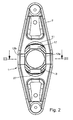
- die Ausrückvorrichtung gemäß Figur 1 in der Vorderansicht;
- Figur 3
- die Ausrückvorrichtung in einer Schnittdarstellung gemäß der Linie 3 - 3 aus Figur 2;
- Figur 4
- in einem vergrößerten Maßstab die Einzelheit "Z" gemäß Figur 3;
- Figur 5
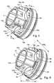
- in einer Perspektive ein Gehäuse der erfindungsgemäßen Ausrückvorrichtung in Verbindung mit einem Ausrücklager;
- Figur 6
- ein zu Figur 5 alternativ gestaltetes Gehäuse in Verbindung mit einem Ausrücklager;
- Figur 7
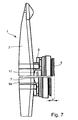
- die Ausrückvorrichtung gemäß Figur 1, die den Höhenausgleich verdeutlicht.
- In Figur 1 ist eine Ausrückvorrichtung 1 dargestellt, die einen Betätigungshebel 2, ein Gehäuse 3 sowie ein Ausrücklager 4 umfasst. Im Einbauzustand ist der Betätigungshebel 2 mit einem Ende an einem ortsfesten Lagerpunkt 5 abgestützt. Zur Betätigung einer Schalttrennkupplung 6, von der eine Tellerfeder dargestellt ist, wird auf das weitere Ende des Betätigungshebels 2 eine in Pfeilrichtung wirkende Kraft ausgeübt, wodurch das Ausrücklager 4 sich axial ebenfalls in Pfeilrichtung verschiebt und dabei einen Kraftfluss über die Schalttrennkupplung 6 unterbricht, um beispielsweise einen Gangwechsel des Schaltgetriebes zu ermöglichen. Zur Erzielung einer möglichst momentenfreien, reibungsarmen und verschleißmindernden Kraftübertragung von dem schwenkbaren Betätigungshebel 2 auf das axial verschiebbare Gehäuse 3 ist zwischen diesen Bauteilen eine weitestgehend linienberührte Kontaktzone 7 vorgesehen. Dazu bildet das Gehäuse 3 zwei erhaben ausgeführte Anlageflächen 8a, 8b, ausgebildet als axial vorstehende Ansätze 9a, 9b, die stirnseitig konvex bzw. ballig gestaltet sind und mit einer weitestgehend geraden bzw. ebenen Gegenfläche 10 kraftschlüssig an dem Betätigungshebel 2 anliegen.
- Wie die Figur 2 verdeutlicht, ist das Gehäuse 3 formschlüssig in eine Aufnahme 11 des Betätigungshebels 2 eingesetzt. Dazu weist das Gehäuse 3 zwei parallele Abflachungen 12a, 12b, die in eine weitestgehend korrespondierend gestaltete Aufnahme 11 des Betätigungshebels 2 eingesetzt ist. Damit ist das Gehäuses 3 formschlüssig, verdrehgesichert in dem Betätigungshebel 2 fixiert, wobei gleichzeitig funktionsbedingt eine begrenzte Verschiebung des Gehäuses 3 in Längsrichtung des Betätigungshebels 2 möglich ist.
- Die zu einer Baueinheit zusammengefügten Bauteile der Ausrückvorrichtung 1 sind unverlierbar miteinander verbunden. Dabei ist das Gehäuse 3 mittels einer in den Figuren 3 und 4 abgebildeten Schnappverbindung 13 verliergesichert zusammengefügt. Die Schnappverbindung 13 umfasst zumindest einen Fixiernocken 14, der wie in Figur 4 abgebildet, in der Einbaulage eine Wandung 15 des Betätigungshebels 2 hintergreift.
- Mittels einer in Figur 1 abgebildeten optischen Anzeige 16 erfolgt eine Überprüfung der Einbaulage des Gehäuses 3 gegenüber dem Betätigungshebel 2. Eine korrekte Einbaulage ist erreicht, sobald eine auf dem Ansatz 9a aufgebrachte Kennzeichnung 17 sichtbar ist und nicht von einem Steg 24 des Betätigungshebels 2 verdeckt ist.
- Die Figur 3 verdeutlicht den Aufbau des Gehäuses 3, das gleichzeitig als Trägerteil für das Ausrücklager 4 dient. Ein äußerer Lagerring 23 des Ausrücklagers 4 ist dabei drehstarr an dem Gehäuse 3 befestigt. An einem weiteren inneren Lagerring 20 des Ausrücklagers 4 stützt sich ein Einstellring 21 ab, der stirnseitig mit einer Tellerfeder der Schalttrennkupplung 6 in Verbindung steht.
- Die Figuren 5 und 6 zeigen das Gehäuse 3 in Verbindung mit dem Ausrücklager 4 in einer Perspektive. Diese Darstellungen verdeutlichen insbesondere die erfindungsgemäße konstruktiv unterschiedlich gestaltete mit "h" bzw. "h1" gekennzeichnete Kontaktzone 7 an dem Gehäuse 3 gegenüber dem Betätigungshebel 2, zur Erzielung eines Höhenausgleichs "S" gemäß Figur 7. Dazu umfasst das Gehäuse 3 jeweils vier Anlageflächen 8a, 8b; 18a, 18b. Der Vorteil einen Hebel für zwei verschiedene Anwendungen einzusetzen, wird durch zwei Schlüsselweiten SW1 und SW2 sichergestellt. Die axial vorstehenden Ansätze 19a, 19b der Anlageflächen 18a, 18b übertreffen dabei die Länge der weiteren axialen Ansätze 9a, 9b der Anlageflächen 8a, 8b. Durch eine Verdrehung des Gehäuses 3 jeweils um 90° gegenüber dem Betätigungshebel 2 stellen sich unterschiedliche Bauhöhen der Ausrückvorrichtung 1 ein, wodurch ein Höhenausgleich "S" gemäß Figur 7 erzielbar ist. Die Ausrückvorrichtung 1 ist mit einem gleichem Bauteileumfang für unterschiedliche Schaltgetriebe und/oder Brennkraftmaschinen einsetzbar.
- Die direkt an dem aus Kunststoff hergestellten Gehäuse 3 angeformten Anlageflächen 8a, 8b; 18a, 18b in Verbindung mit den zugehörigen axialen Ansätzen 9a, 9b; 19a, 19b gewährleisten eine unterschiedliche Bauhöhe bzw. ermöglichen einen Höhenausgleich "S". Das Gehäuse 3 gemäß Figur 5 weist im Bereich der Abflachung 22a eine Abstimmrippe 25 auf, die insbesondere dazu dient eine Fehlmontage des Gehäuses 3 zu unterbinden. Diese Abstimmrippe 25 verhindert einerseits bei einer Handmontage eine falsche Zuordnung des Gehäuses 3 in den Betätigungshebel 2. Andererseits weist die Abstimmrippe 25 eine Sollbruchstelle auf, die nach Aufbringen einer erhöhten Einpresskraft abschert und damit einen ungehinderten Einbau des Gehäuses 3 in beiden Positionen ermöglicht.
- Im Unterschied zu Figur 5 weist das Gehäuse 3 gemäß Figur 6 eine weitestgehend ringförmig gestaltete Armierung 26 auf, die als separates Bauteil alle Anlageflächen 8a, 8b; 18a, 18b einschließt. Die Armierung 26 ist innenseitig der Kontur der Mantelfläche 27 des Gehäuses 3 angepasst und damit formschlüssig, verdrehgesichert mit dem Gehäuse 3 verbunden. Die gegenüber dem Kunststoff des Gehäuses 3 eine höhere Festigkeit aufweisende Armierung 26 verringert bzw. vermeidet einen Verschleiß im Bereich der Kontaktzone 7 zwischen dem Gehäuse 3 und dem Betätigungshebel 2. Vorteilhaft weist die Armierung 26 unterschiedliche Schlüsselweiten im Bereich der Anlageflächen 8a, 8b; 18a, 18b auf die eine automatisierte Montage vereinfacht. Damit kann das Gehäuse 3 stets von einem Werkzeug gleicher Schlüsselweite aufgenommen werden und mit dem Betätigungshebel 2 zusammengefügt werden, wodurch eine Fehlmontage unterbleibt. Dazu bietet es sich an, die sich zwischen den Anlageflächen 8a, 8b einstellende Schlüsselweite "SW1" größer auszubilden als die weitere Schlüsselweise "SW2", die sich zwischen den Anlageflächen 18a, 18b einstellt.
- Die Figur 7 zeigt den möglichen Höhenausgleich "S" der sich durch die unterschiedliche Zuordnung des Gehäuses 3 gegenüber dem Betätigungshebel 2 einstellt. Dieser Höhenausgleich "S" ist realisierbar, indem das Gehäuse 3 um 90° gegenüber dem Betätigungshebel 2 verdreht eingesetzt wird.
-
- 1
- Ausrückvorrichtung
- 2
- Betätigungshebel
- 3
- Gehäuse
- 4
- Ausrücklager
- 5
- Lagerpunkt
- 6
- Schalttrennkupplung
- 7
- Kontaktzone
- 8a
- Anlagefläche
- 8b
- Anlagefläche
- 9a
- Ansatz
- 9b
- Ansatz
- 10
- Gegenfläche
- 11
- Aufnahme
- 12a
- Abflachung
- 12b
- Abflachung
- 13
- Schnappverbindung
- 14
- Fixiernocken
- 15
- Wandung
- 16
- optische Anzeige
- 17
- Kennzeichnung
- 18a
- Anlagefläche
- 18b
- Anlagefläche
- 19a
- Ansatz
- 19b
- Ansatz
- 20
- Lagerring (innen)
- 21
- Einstellring
- 22a
- Abflachung
- 22b
- Abflachung
- 23
- Lagerring (außen)
- 24
- Steg
- 25
- Abstimmrippe
- 26
- Armierung
- 27
- Mantelfläche
Claims (23)
- Ausrückvorrichtung für eine in Fahrzeugen eingesetzte Schalttrennkupplung (6), umfassend ein eine Antriebswelle beabstandet umschließendes, hohlzylindrisch gestaltetes und axial verschiebbares Gehäuse (3), das über eine Anlagefläche (8a, 8b; 18a, 18b) an einem Betätigungshebel (2) abgestützt ist und weiterhin formschlüssig, spielbehaftet an dem Betätigungshebel (2) befestigt ist und das Gehäuse (3) an dem vom Betätigungshebel (2) abgewandten Ende ein Ausrücklager (4) aufweist dadurch gekennzeichnet, dass,- der Betätigungshebel (2) eine Aufnahme (11) bildet, in der das Gehäuse (3) in zumindest zwei voneinander abweichenden Einbaupositionen fixiert werden kann, wodurch sich eine unterschiedliche Bauhöhe, ein Höhenausgleich "s" der Ausrückvorrichtung (1) einstellt;- das Gehäuse (3) für jede Einbauposition jeweils zwei um 90° versetzte, paarweise angeordnete Anlageflächen (8a, 8b; 18a, 18b) aufweist, über die das Gehäuse (3) an dem Betätigungshebel (2) abgestützt ist.
- Ausrückvorrichtung nach Anspruch 1, wobei das Gehäuse (3) jeder Einbauposition entsprechende Anlageflächen (8a, 8b; 18a, 18b) einschließt, die als axial vorstehende, mit dem Betätigungshebel (2) zusammenwirkende Ansätze (9a, 9b; 19a, 19b) ausgebildet sind.
- Ausrückvorrichtung nach Anspruch 1, bei der das Gehäuse (3) konvex bzw. ballig gestaltete Ansätze (9a, 9b; 19a, 19b) der Anlageflächen (8a, 8b; 18a, 18b) aufweist, die mit einer Gegenfläche (10) des Betätigungshebels (2) Kontaktzonen (7) bilden.
- Ausrückvorrichtung nach Anspruch 1, bei dem die Ansätze (9a, 9b; 19a, 19b) der Anlageflächen (8a, 8b; 18a, 18b) eben bzw. gerade ausgebildet sind.
- Ausrückvorrichtung nach Anspruch 1, die ein aus Kunststoff hergestelltes Gehäuse (3) mit einstückig angeformten Anlageflächen (8a, 8b; 18a, 18b) umfasst.
- Ausrückvorrichtung nach Anspruch 1, bei dem alle Anlageflächen (8a, 8b; 18a, 18b) als eine Armierung (26) ausgebildet sind, die als separates Bauteil dem Gehäuse (3) zugeordnet sind.
- Ausrückvorrichtung nach Anspruch 1, bei der die Ansätze (9a, 9b; 19a, 19b) zumindest stirnseitig oder an der Anlagefläche (8a, 8b; 18a, 18b) eine verschleißmindernde und / oder reibungsmindernde Beschichtung aufweisen.
- Ausrückvorrichtung nach Anspruch 1, wobei das zwei zueinander parallele Abflachungen (12a, 12b) an einer Mantelfläche (27) aufweisende Gehäuse (3) in der Einbaulage formschlüssig in eine mit einer Außenkontur der Mantelfläche (27) korrespondierende Aufnahme (11) des Betätigungshebels (2) eingreift.
- Ausrückvorrichtung nach Anspruch 1, bei dem das Gehäuse (3) zwei unterschiedliche Schlüsselweiten "SW1", "SW2" im Bereich der Mantelfläche (27), insbesondere den Anlageflächen (8a, 8b; 18a, 18b) vorsieht, die zur Werkzeugaufnahme bestimmt sind.
- Ausrückvorrichtung nach Anspruch 1, die zur Vermeidung einer Fehlmontage für jede Einbausituation des Gehäuses (3) eine optische Anzeige (16) einschließt.
- Ausrückvorrichtung nach Anspruch 10, die als optische Anzeige (16) einen Barcode aufweist.
- Ausrückvorrichtung nach Anspruch 10, versehen mit einer optischen Anzeige (16), die nach erfolgter Komplettierung, im Einbauzustand des Gehäuses (3) sichtbar ist.
- Ausrückvorrichtung nach Anspruch 10, die als optische Anzeige (16) vertiefte oder hervortretende Zeichen, wie beispielsweise eine Rippe oder eine Schrift vorsieht.
- Ausrückvorrichtung nach Anspruch 13, wobei eine angeformte, eine Sollbruchstelle einschließende Abstimmrippe (25) einen lageorientierten Einbau des Gehäuses (3) sicherstellt.
- Ausrückvorrichtung nach Anspruch 1, die eine Schnappverbindung (13) zwischen dem Gehäuse (3) und dem Betätigungshebel (2) umfasst.
- Ausrückvorrichtung nach Anspruch 15, deren Schnappverbindung (13) als Fixiernocken (14) gestaltete Durchstellungen bzw. Ausklinkungen einschließt, die formschlüssig in eine korrespondierende Aussparung eingreift oder an einer Wandung (15) des Betätigungshebels (2) verschnappt.
- Ausrückvorrichtung nach Anspruch 1, die einen Betätigungshebel (2) aus Stahlblech umfasst, der spanlos durch ein Tiefziehverfahren hergestellt ist.
- Ausrückvorrichtung nach Anspruch 1, bei der alle Bauteile der Ausrückvorrichtung (1), das Gehäuse (3), der Betätigungshebel (2) sowie das Ausrücklager (4) zu einer Baueinheit unverlierbar zusammengefügt sind.
- Ausrückvorrichtung nach Anspruch 1, wobei das Gehäuse (3) um 90° versetzte, paarweise angeordnete Anlageflächen (8a, 8b, 18a, 18b) aufweist, deren Abflachungen (12a, 12b, 22a, 22b) unterschiedlichen Schlüsselweiten zugeordnet sind.
- Ausrückvorrichtung nach Anspruch 1, wobei das Gehäuse (3) um 90° versetzte, paarweise mit unterschiedlicher Bauhöhe angeordnete Anlageflächen (8a, 8b, 18a, 18b) aufweist, deren Abflachungen (12a, 12b, 22a, 22b) unterschiedlichen Schlüsselweiten zugeordnet sind.
- Ausrückvorrichtung insbesondere nach Anspruch 6, wobei mindestens eine der paarweise ausgeführten Anlageflächen als separate Bauteile dem Gehäuse (3) zugeordnet sind und mit diesem form- und / oder stoffschlüssig verbunden sind.
- Ausrückvorrichtung insbesondere nach Anspruch 6, wobei die Armierung (26) als Mehrstoffschicht direkt bei der Herstellung des Gehäuses im Mehrstoffspritzverfahren gefertigt wird und mit dem Grundgehäuse form- und /oder stoffschlüssig verbunden sind.
- Ausrückvorrichtung nach einem der zuvor genannten Ansprüche, wobei die unterschiedlichen Kontaktstellen des Gehäuses oder der Armierung zur Kennzeichnung paarweise unterschiedliche Werkstoffeinfärbungen aufweisen, oder farblich unterschiedlich gekennzeichnet sind.
Applications Claiming Priority (1)
| Application Number | Priority Date | Filing Date | Title |
|---|---|---|---|
| DE102004061679A DE102004061679A1 (de) | 2004-12-22 | 2004-12-22 | Ausrückvorrichtung |
Publications (2)
| Publication Number | Publication Date |
|---|---|
| EP1674751A1 true EP1674751A1 (de) | 2006-06-28 |
| EP1674751B1 EP1674751B1 (de) | 2007-09-05 |
Family
ID=35830650
Family Applications (1)
| Application Number | Title | Priority Date | Filing Date |
|---|---|---|---|
| EP05024493A Expired - Lifetime EP1674751B1 (de) | 2004-12-22 | 2005-11-10 | Ausrückvorrichtung |
Country Status (7)
| Country | Link |
|---|---|
| US (1) | US7438170B2 (de) |
| EP (1) | EP1674751B1 (de) |
| JP (1) | JP4872077B2 (de) |
| CN (1) | CN1793678B (de) |
| AT (1) | ATE372471T1 (de) |
| BR (1) | BRPI0505603A (de) |
| DE (2) | DE102004061679A1 (de) |
Families Citing this family (4)
| Publication number | Priority date | Publication date | Assignee | Title |
|---|---|---|---|---|
| WO2010015228A1 (de) * | 2008-08-07 | 2010-02-11 | Luk Lamellen Und Kupplungsbau Beteiligungs Kg | Doppelkupplung |
| US9175732B2 (en) | 2010-05-25 | 2015-11-03 | Honda Motor Co., Ltd. | Variable speed transmission clutch linkage |
| CN102278384B (zh) * | 2011-05-31 | 2013-05-29 | 姜成立 | 摩擦离合器及其分离结合装置 |
| DE102012219496A1 (de) * | 2012-10-25 | 2014-04-30 | Schaeffler Technologies Gmbh & Co. Kg | Ausrückhebel |
Citations (6)
| Publication number | Priority date | Publication date | Assignee | Title |
|---|---|---|---|---|
| DE7600543U1 (de) | Skf Kugellagerfabriken Gmbh, 8720 Schweinfurt | |||
| US3277988A (en) * | 1964-05-14 | 1966-10-11 | Nadella | Clutch having thrust bearing operated through a universal joint |
| FR2304826A1 (fr) | 1975-03-19 | 1976-10-15 | Ferodo Sa | Mecanisme de commande en rotation notamment pour vehicule automobile, et embrayage et butee de debrayage propres a la realisation d'un tel mecanisme |
| DE2830249A1 (de) | 1977-07-08 | 1979-01-25 | Ferodo Sa | Ausrueckvorrichtung fuer eine kupplung |
| JPH0914291A (ja) * | 1995-06-27 | 1997-01-14 | Nissan Diesel Motor Co Ltd | クラッチ装置 |
| US5979632A (en) * | 1997-10-10 | 1999-11-09 | Mannesmann Sachs Ag | Disengagement mechanism for clutch actuation in motor vehicles |
Family Cites Families (14)
| Publication number | Priority date | Publication date | Assignee | Title |
|---|---|---|---|---|
| CH437932A (fr) * | 1964-05-14 | 1967-06-15 | Pitner Alfred | Dispositif de commande d'un embrayage comportant une butée à aiguilles ou à rouleaux |
| US4267913A (en) * | 1978-02-21 | 1981-05-19 | Skf Kugellagerfabriken Gmbh | Clutch release device |
| FR2505954A1 (fr) * | 1981-05-15 | 1982-11-19 | Valeo | Butee de debrayage, notamment pour vehicule automobile, procede pour le montage d'une telle butee de debrayage sur une fourchette de commande, et fourchette de commande adaptee a un tel procede |
| US4601377A (en) * | 1981-10-23 | 1986-07-22 | Dana Corporation | Clutch adjustment method |
| FR2531509B1 (fr) * | 1982-08-03 | 1987-10-09 | Valeo | Butee de debrayage autocentreuse a autocentrage maintenu, notamment pour vehicule automobile |
| US4667799A (en) * | 1985-05-30 | 1987-05-26 | Dana Corporation | Shim cap device for clutch lever adjustment |
| DE3810369C2 (de) * | 1988-03-26 | 1998-01-22 | Mannesmann Sachs Ag | Ausrücklager mit Haltenasen |
| JPH01176225U (de) * | 1988-06-01 | 1989-12-15 | ||
| US5273146A (en) * | 1991-04-09 | 1993-12-28 | Nsk Ltd. | Bearing unit for clutch release |
| JP3414611B2 (ja) * | 1997-02-20 | 2003-06-09 | ダイハツ工業株式会社 | クラッチ装置のレリーズフォーク構造 |
| US6585772B2 (en) * | 1997-03-27 | 2003-07-01 | Smith & Nephew, Inc. | Method of surface oxidizing zirconium and zirconium alloys and resulting product |
| JP2000055078A (ja) * | 1998-08-10 | 2000-02-22 | Ntn Corp | 自動調心型クラッチレリーズ軸受装置 |
| DE10000893B4 (de) * | 2000-01-12 | 2011-01-13 | Zf Sachs Ag | Ausrückvorrichtung für eine Kupplung eines Antriebsaggregates für Kraftfahrzeuge |
| JP2002155966A (ja) * | 2000-11-21 | 2002-05-31 | Nsk Ltd | クラッチレリーズ軸受装置 |
-
2004
- 2004-12-22 DE DE102004061679A patent/DE102004061679A1/de not_active Ceased
-
2005
- 2005-11-10 AT AT05024493T patent/ATE372471T1/de not_active IP Right Cessation
- 2005-11-10 DE DE502005001417T patent/DE502005001417D1/de not_active Expired - Lifetime
- 2005-11-10 EP EP05024493A patent/EP1674751B1/de not_active Expired - Lifetime
- 2005-12-20 BR BRPI0505603-9A patent/BRPI0505603A/pt not_active Application Discontinuation
- 2005-12-21 CN CN200510133806.9A patent/CN1793678B/zh not_active Expired - Fee Related
- 2005-12-22 JP JP2005370328A patent/JP4872077B2/ja not_active Expired - Fee Related
- 2005-12-22 US US11/315,658 patent/US7438170B2/en not_active Expired - Fee Related
Patent Citations (6)
| Publication number | Priority date | Publication date | Assignee | Title |
|---|---|---|---|---|
| DE7600543U1 (de) | Skf Kugellagerfabriken Gmbh, 8720 Schweinfurt | |||
| US3277988A (en) * | 1964-05-14 | 1966-10-11 | Nadella | Clutch having thrust bearing operated through a universal joint |
| FR2304826A1 (fr) | 1975-03-19 | 1976-10-15 | Ferodo Sa | Mecanisme de commande en rotation notamment pour vehicule automobile, et embrayage et butee de debrayage propres a la realisation d'un tel mecanisme |
| DE2830249A1 (de) | 1977-07-08 | 1979-01-25 | Ferodo Sa | Ausrueckvorrichtung fuer eine kupplung |
| JPH0914291A (ja) * | 1995-06-27 | 1997-01-14 | Nissan Diesel Motor Co Ltd | クラッチ装置 |
| US5979632A (en) * | 1997-10-10 | 1999-11-09 | Mannesmann Sachs Ag | Disengagement mechanism for clutch actuation in motor vehicles |
Non-Patent Citations (1)
| Title |
|---|
| PATENT ABSTRACTS OF JAPAN vol. 1997, no. 05 30 May 1997 (1997-05-30) * |
Also Published As
| Publication number | Publication date |
|---|---|
| DE502005001417D1 (de) | 2007-10-18 |
| CN1793678B (zh) | 2011-07-20 |
| JP2006177558A (ja) | 2006-07-06 |
| DE102004061679A1 (de) | 2006-07-06 |
| EP1674751B1 (de) | 2007-09-05 |
| BRPI0505603A (pt) | 2006-09-19 |
| CN1793678A (zh) | 2006-06-28 |
| US20060169568A1 (en) | 2006-08-03 |
| ATE372471T1 (de) | 2007-09-15 |
| JP4872077B2 (ja) | 2012-02-08 |
| US7438170B2 (en) | 2008-10-21 |
Similar Documents
| Publication | Publication Date | Title |
|---|---|---|
| EP2739519B1 (de) | Lenkungsanordnung | |
| EP1243804B1 (de) | Selbsteinstellendes Kupplungsausrücklager | |
| DE102007051475A1 (de) | Verbindung eines Achsversatzausgleichselements und eines Innenrings eines Wälzlagers | |
| EP2676009B1 (de) | Betätigungsmodul für mindestens ein gaswechselventil einer brennkraftmaschine | |
| WO1999064757A1 (de) | Führungshülse für einen nehmerzylinder | |
| DE19581000B4 (de) | Übertragungselement für eine Getriebeschaltung | |
| DE102007042212A1 (de) | Schalteinheit für ein Schaltgetriebe eines Kraftfahrzeugs | |
| EP2078879A1 (de) | Synchronisiereinrichtung für Schaltgetriebe | |
| EP1674751B1 (de) | Ausrückvorrichtung | |
| EP1125066B1 (de) | Dichtelement für ein ausrücklager | |
| EP1553309B1 (de) | Vorrichtung zur Befestigung eines Bauteils an Mantelrohre unterschiedlichen Durchmessers | |
| EP1143321B1 (de) | Handschaltung für ein Kraftfahrzeug | |
| DE102010045792B4 (de) | Kupplungsaggregat | |
| EP1870610B1 (de) | Hebelsystem sowie Verfahren zu dessen Montage | |
| DE102006034013A1 (de) | Anbindung eines Zentralausrückers an eine Kupplung | |
| DE102022114373B3 (de) | Kopplungseinheit zum Koppeln und Entkoppeln zweier Antriebselemente eines Antriebsstrangs | |
| DE102020124569A1 (de) | Antreibende nockenriemenscheibe for elektrisches servolen-kungssystem | |
| EP2334957B1 (de) | Schaltanordnung für ein schaltgetriebe | |
| DE19846988A1 (de) | Betätigungsvorrichtung für eine Reibungskupplung | |
| EP3557011B1 (de) | Lagerrahmen oder zylinderkopfhaube einer brennkraftmaschine | |
| DE10117573A1 (de) | Lageranordnung sowie Elektroantrieb mit einer solchen Lageranordnung | |
| DE102012221516A1 (de) | Halteklammer für Motorkomponenten | |
| EP0908640A1 (de) | Ausrückeinrichtung zur Kupplungsbetätigung bei Kraftfahrzeugen | |
| DE10246937A1 (de) | Halteclip für ein Kupplungsausrücklager | |
| EP2206225A2 (de) | Elektromotorischer hilfsantrieb für fahrzeuge sowie verfahren zum herstellen bzw. montieren eines solchen antriebs |
Legal Events
| Date | Code | Title | Description |
|---|---|---|---|
| PUAI | Public reference made under article 153(3) epc to a published international application that has entered the european phase |
Free format text: ORIGINAL CODE: 0009012 |
|
| 17P | Request for examination filed |
Effective date: 20051110 |
|
| AK | Designated contracting states |
Kind code of ref document: A1 Designated state(s): AT BE BG CH CY CZ DE DK EE ES FI FR GB GR HU IE IS IT LI LT LU LV MC NL PL PT RO SE SI SK TR |
|
| AX | Request for extension of the european patent |
Extension state: AL BA HR MK YU |
|
| 17Q | First examination report despatched |
Effective date: 20061130 |
|
| AKX | Designation fees paid |
Designated state(s): AT BE BG CH CY CZ DE DK EE ES FI FR GB GR HU IE IS IT LI LT LU LV MC NL PL PT RO SE SI SK TR |
|
| GRAP | Despatch of communication of intention to grant a patent |
Free format text: ORIGINAL CODE: EPIDOSNIGR1 |
|
| GRAS | Grant fee paid |
Free format text: ORIGINAL CODE: EPIDOSNIGR3 |
|
| GRAA | (expected) grant |
Free format text: ORIGINAL CODE: 0009210 |
|
| AK | Designated contracting states |
Kind code of ref document: B1 Designated state(s): AT BE BG CH CY CZ DE DK EE ES FI FR GB GR HU IE IS IT LI LT LU LV MC NL PL PT RO SE SI SK TR |
|
| REG | Reference to a national code |
Ref country code: GB Ref legal event code: FG4D Free format text: NOT ENGLISH |
|
| REG | Reference to a national code |
Ref country code: CH Ref legal event code: EP |
|
| REF | Corresponds to: |
Ref document number: 502005001417 Country of ref document: DE Date of ref document: 20071018 Kind code of ref document: P |
|
| REG | Reference to a national code |
Ref country code: IE Ref legal event code: FG4D Free format text: LANGUAGE OF EP DOCUMENT: GERMAN |
|
| PG25 | Lapsed in a contracting state [announced via postgrant information from national office to epo] |
Ref country code: FI Free format text: LAPSE BECAUSE OF FAILURE TO SUBMIT A TRANSLATION OF THE DESCRIPTION OR TO PAY THE FEE WITHIN THE PRESCRIBED TIME-LIMIT Effective date: 20070905 Ref country code: LT Free format text: LAPSE BECAUSE OF FAILURE TO SUBMIT A TRANSLATION OF THE DESCRIPTION OR TO PAY THE FEE WITHIN THE PRESCRIBED TIME-LIMIT Effective date: 20070905 Ref country code: ES Free format text: LAPSE BECAUSE OF FAILURE TO SUBMIT A TRANSLATION OF THE DESCRIPTION OR TO PAY THE FEE WITHIN THE PRESCRIBED TIME-LIMIT Effective date: 20071216 |
|
| PG25 | Lapsed in a contracting state [announced via postgrant information from national office to epo] |
Ref country code: PL Free format text: LAPSE BECAUSE OF FAILURE TO SUBMIT A TRANSLATION OF THE DESCRIPTION OR TO PAY THE FEE WITHIN THE PRESCRIBED TIME-LIMIT Effective date: 20070905 |
|
| NLV1 | Nl: lapsed or annulled due to failure to fulfill the requirements of art. 29p and 29m of the patents act | ||
| PG25 | Lapsed in a contracting state [announced via postgrant information from national office to epo] |
Ref country code: LV Free format text: LAPSE BECAUSE OF FAILURE TO SUBMIT A TRANSLATION OF THE DESCRIPTION OR TO PAY THE FEE WITHIN THE PRESCRIBED TIME-LIMIT Effective date: 20070905 |
|
| GBV | Gb: ep patent (uk) treated as always having been void in accordance with gb section 77(7)/1977 [no translation filed] | ||
| REG | Reference to a national code |
Ref country code: IE Ref legal event code: FD4D |
|
| PG25 | Lapsed in a contracting state [announced via postgrant information from national office to epo] |
Ref country code: NL Free format text: LAPSE BECAUSE OF FAILURE TO SUBMIT A TRANSLATION OF THE DESCRIPTION OR TO PAY THE FEE WITHIN THE PRESCRIBED TIME-LIMIT Effective date: 20070905 Ref country code: GR Free format text: LAPSE BECAUSE OF FAILURE TO SUBMIT A TRANSLATION OF THE DESCRIPTION OR TO PAY THE FEE WITHIN THE PRESCRIBED TIME-LIMIT Effective date: 20071206 |
|
| EN | Fr: translation not filed | ||
| PG25 | Lapsed in a contracting state [announced via postgrant information from national office to epo] |
Ref country code: CZ Free format text: LAPSE BECAUSE OF FAILURE TO SUBMIT A TRANSLATION OF THE DESCRIPTION OR TO PAY THE FEE WITHIN THE PRESCRIBED TIME-LIMIT Effective date: 20070905 Ref country code: GB Free format text: LAPSE BECAUSE OF FAILURE TO SUBMIT A TRANSLATION OF THE DESCRIPTION OR TO PAY THE FEE WITHIN THE PRESCRIBED TIME-LIMIT Effective date: 20070905 Ref country code: IS Free format text: LAPSE BECAUSE OF FAILURE TO SUBMIT A TRANSLATION OF THE DESCRIPTION OR TO PAY THE FEE WITHIN THE PRESCRIBED TIME-LIMIT Effective date: 20080105 Ref country code: SK Free format text: LAPSE BECAUSE OF FAILURE TO SUBMIT A TRANSLATION OF THE DESCRIPTION OR TO PAY THE FEE WITHIN THE PRESCRIBED TIME-LIMIT Effective date: 20070905 Ref country code: PT Free format text: LAPSE BECAUSE OF FAILURE TO SUBMIT A TRANSLATION OF THE DESCRIPTION OR TO PAY THE FEE WITHIN THE PRESCRIBED TIME-LIMIT Effective date: 20080206 Ref country code: IE Free format text: LAPSE BECAUSE OF FAILURE TO SUBMIT A TRANSLATION OF THE DESCRIPTION OR TO PAY THE FEE WITHIN THE PRESCRIBED TIME-LIMIT Effective date: 20070905 |
|
| BERE | Be: lapsed |
Owner name: SCHAEFFLER K.G. Effective date: 20071130 |
|
| PG25 | Lapsed in a contracting state [announced via postgrant information from national office to epo] |
Ref country code: MC Free format text: LAPSE BECAUSE OF NON-PAYMENT OF DUE FEES Effective date: 20071130 Ref country code: SE Free format text: LAPSE BECAUSE OF FAILURE TO SUBMIT A TRANSLATION OF THE DESCRIPTION OR TO PAY THE FEE WITHIN THE PRESCRIBED TIME-LIMIT Effective date: 20071205 Ref country code: RO Free format text: LAPSE BECAUSE OF FAILURE TO SUBMIT A TRANSLATION OF THE DESCRIPTION OR TO PAY THE FEE WITHIN THE PRESCRIBED TIME-LIMIT Effective date: 20070905 |
|
| PLBE | No opposition filed within time limit |
Free format text: ORIGINAL CODE: 0009261 |
|
| STAA | Information on the status of an ep patent application or granted ep patent |
Free format text: STATUS: NO OPPOSITION FILED WITHIN TIME LIMIT |
|
| PG25 | Lapsed in a contracting state [announced via postgrant information from national office to epo] |
Ref country code: DK Free format text: LAPSE BECAUSE OF FAILURE TO SUBMIT A TRANSLATION OF THE DESCRIPTION OR TO PAY THE FEE WITHIN THE PRESCRIBED TIME-LIMIT Effective date: 20070905 |
|
| ET | Fr: translation filed | ||
| REG | Reference to a national code |
Ref country code: FR Ref legal event code: EERR Free format text: CORRECTION DE BOPI 08/18 - BREVETS EUROPEENS DONT LA TRADUCTION N A PAS ETE REMISE A L INPI. IL Y A LIEU DE SUPPRIMER : LA MENTION DE LA NON-REMISE. LA REMISE DE LA TRADUCTION EST PUBLIEE DANS LE PRESENT BOPI. |
|
| 26N | No opposition filed |
Effective date: 20080606 |
|
| PG25 | Lapsed in a contracting state [announced via postgrant information from national office to epo] |
Ref country code: FR Free format text: LAPSE BECAUSE OF FAILURE TO SUBMIT A TRANSLATION OF THE DESCRIPTION OR TO PAY THE FEE WITHIN THE PRESCRIBED TIME-LIMIT Effective date: 20080502 Ref country code: BE Free format text: LAPSE BECAUSE OF NON-PAYMENT OF DUE FEES Effective date: 20071130 |
|
| PG25 | Lapsed in a contracting state [announced via postgrant information from national office to epo] |
Ref country code: EE Free format text: LAPSE BECAUSE OF FAILURE TO SUBMIT A TRANSLATION OF THE DESCRIPTION OR TO PAY THE FEE WITHIN THE PRESCRIBED TIME-LIMIT Effective date: 20070905 |
|
| PG25 | Lapsed in a contracting state [announced via postgrant information from national office to epo] |
Ref country code: AT Free format text: LAPSE BECAUSE OF NON-PAYMENT OF DUE FEES Effective date: 20071110 |
|
| PG25 | Lapsed in a contracting state [announced via postgrant information from national office to epo] |
Ref country code: SI Free format text: LAPSE BECAUSE OF FAILURE TO SUBMIT A TRANSLATION OF THE DESCRIPTION OR TO PAY THE FEE WITHIN THE PRESCRIBED TIME-LIMIT Effective date: 20070905 |
|
| PG25 | Lapsed in a contracting state [announced via postgrant information from national office to epo] |
Ref country code: CY Free format text: LAPSE BECAUSE OF FAILURE TO SUBMIT A TRANSLATION OF THE DESCRIPTION OR TO PAY THE FEE WITHIN THE PRESCRIBED TIME-LIMIT Effective date: 20070905 |
|
| PG25 | Lapsed in a contracting state [announced via postgrant information from national office to epo] |
Ref country code: BG Free format text: LAPSE BECAUSE OF FAILURE TO SUBMIT A TRANSLATION OF THE DESCRIPTION OR TO PAY THE FEE WITHIN THE PRESCRIBED TIME-LIMIT Effective date: 20071205 Ref country code: LU Free format text: LAPSE BECAUSE OF NON-PAYMENT OF DUE FEES Effective date: 20071110 |
|
| PG25 | Lapsed in a contracting state [announced via postgrant information from national office to epo] |
Ref country code: HU Free format text: LAPSE BECAUSE OF FAILURE TO SUBMIT A TRANSLATION OF THE DESCRIPTION OR TO PAY THE FEE WITHIN THE PRESCRIBED TIME-LIMIT Effective date: 20080306 Ref country code: TR Free format text: LAPSE BECAUSE OF FAILURE TO SUBMIT A TRANSLATION OF THE DESCRIPTION OR TO PAY THE FEE WITHIN THE PRESCRIBED TIME-LIMIT Effective date: 20070905 |
|
| REG | Reference to a national code |
Ref country code: CH Ref legal event code: PL |
|
| PG25 | Lapsed in a contracting state [announced via postgrant information from national office to epo] |
Ref country code: CH Free format text: LAPSE BECAUSE OF NON-PAYMENT OF DUE FEES Effective date: 20091130 Ref country code: LI Free format text: LAPSE BECAUSE OF NON-PAYMENT OF DUE FEES Effective date: 20091130 |
|
| REG | Reference to a national code |
Ref country code: DE Ref legal event code: R081 Ref document number: 502005001417 Country of ref document: DE Owner name: SCHAEFFLER TECHNOLOGIES AG & CO. KG, DE Free format text: FORMER OWNER: SCHAEFFLER TECHNOLOGIES GMBH & CO. KG, 91074 HERZOGENAURACH, DE Effective date: 20120828 Ref country code: DE Ref legal event code: R081 Ref document number: 502005001417 Country of ref document: DE Owner name: SCHAEFFLER TECHNOLOGIES GMBH & CO. KG, DE Free format text: FORMER OWNER: SCHAEFFLER TECHNOLOGIES GMBH & CO. KG, 91074 HERZOGENAURACH, DE Effective date: 20120828 |
|
| REG | Reference to a national code |
Ref country code: DE Ref legal event code: R081 Ref document number: 502005001417 Country of ref document: DE Owner name: SCHAEFFLER TECHNOLOGIES AG CO. KG, DE Free format text: FORMER OWNER: SCHAEFFLER TECHNOLOGIES AG CO. KG, 91074 HERZOGENAURACH, DE Effective date: 20140213 Ref country code: DE Ref legal event code: R081 Ref document number: 502005001417 Country of ref document: DE Owner name: SCHAEFFLER TECHNOLOGIES AG & CO. KG, DE Free format text: FORMER OWNER: SCHAEFFLER TECHNOLOGIES AG & CO. KG, 91074 HERZOGENAURACH, DE Effective date: 20140213 Ref country code: DE Ref legal event code: R081 Ref document number: 502005001417 Country of ref document: DE Owner name: SCHAEFFLER TECHNOLOGIES GMBH & CO. KG, DE Free format text: FORMER OWNER: SCHAEFFLER TECHNOLOGIES AG & CO. KG, 91074 HERZOGENAURACH, DE Effective date: 20140213 |
|
| REG | Reference to a national code |
Ref country code: DE Ref legal event code: R081 Ref document number: 502005001417 Country of ref document: DE Owner name: SCHAEFFLER TECHNOLOGIES AG & CO. KG, DE Free format text: FORMER OWNER: SCHAEFFLER TECHNOLOGIES GMBH & CO. KG, 91074 HERZOGENAURACH, DE Effective date: 20150213 |
|
| REG | Reference to a national code |
Ref country code: FR Ref legal event code: PLFP Year of fee payment: 11 |
|
| REG | Reference to a national code |
Ref country code: FR Ref legal event code: PLFP Year of fee payment: 12 |
|
| PGFP | Annual fee paid to national office [announced via postgrant information from national office to epo] |
Ref country code: FR Payment date: 20161128 Year of fee payment: 12 |
|
| PGFP | Annual fee paid to national office [announced via postgrant information from national office to epo] |
Ref country code: IT Payment date: 20161123 Year of fee payment: 12 |
|
| PGFP | Annual fee paid to national office [announced via postgrant information from national office to epo] |
Ref country code: DE Payment date: 20170131 Year of fee payment: 12 |
|
| REG | Reference to a national code |
Ref country code: DE Ref legal event code: R119 Ref document number: 502005001417 Country of ref document: DE |
|
| REG | Reference to a national code |
Ref country code: FR Ref legal event code: ST Effective date: 20180731 |
|
| PG25 | Lapsed in a contracting state [announced via postgrant information from national office to epo] |
Ref country code: IT Free format text: LAPSE BECAUSE OF NON-PAYMENT OF DUE FEES Effective date: 20171110 Ref country code: DE Free format text: LAPSE BECAUSE OF NON-PAYMENT OF DUE FEES Effective date: 20180602 Ref country code: FR Free format text: LAPSE BECAUSE OF NON-PAYMENT OF DUE FEES Effective date: 20171130 |
|
| P01 | Opt-out of the competence of the unified patent court (upc) registered |
Effective date: 20230523 |