EP1674172A1 - Method for manufacturing high-pressure piping part and structure thereof - Google Patents
Method for manufacturing high-pressure piping part and structure thereof Download PDFInfo
- Publication number
- EP1674172A1 EP1674172A1 EP05027001A EP05027001A EP1674172A1 EP 1674172 A1 EP1674172 A1 EP 1674172A1 EP 05027001 A EP05027001 A EP 05027001A EP 05027001 A EP05027001 A EP 05027001A EP 1674172 A1 EP1674172 A1 EP 1674172A1
- Authority
- EP
- European Patent Office
- Prior art keywords
- passage
- billet
- piping part
- body structure
- extrusion
- Prior art date
- Legal status (The legal status is an assumption and is not a legal conclusion. Google has not performed a legal analysis and makes no representation as to the accuracy of the status listed.)
- Granted
Links
- 238000000034 method Methods 0.000 title claims description 25
- 238000004519 manufacturing process Methods 0.000 title claims description 19
- 238000001125 extrusion Methods 0.000 claims abstract description 94
- 239000000835 fiber Substances 0.000 claims abstract description 55
- 239000012530 fluid Substances 0.000 claims description 15
- 239000000446 fuel Substances 0.000 claims description 13
- 238000003825 pressing Methods 0.000 claims description 12
- 238000002485 combustion reaction Methods 0.000 claims description 8
- 239000002994 raw material Substances 0.000 claims description 5
- 238000005553 drilling Methods 0.000 claims description 4
- 238000010438 heat treatment Methods 0.000 claims 2
- 238000005452 bending Methods 0.000 claims 1
- 239000000463 material Substances 0.000 description 20
- 238000005242 forging Methods 0.000 description 15
- 238000012986 modification Methods 0.000 description 4
- 230000004048 modification Effects 0.000 description 4
- 229910000831 Steel Inorganic materials 0.000 description 3
- 238000005520 cutting process Methods 0.000 description 3
- 238000010586 diagram Methods 0.000 description 3
- 239000010959 steel Substances 0.000 description 3
- 239000000470 constituent Substances 0.000 description 2
- 238000007796 conventional method Methods 0.000 description 2
- NINIDFKCEFEMDL-UHFFFAOYSA-N Sulfur Chemical compound [S] NINIDFKCEFEMDL-UHFFFAOYSA-N 0.000 description 1
- 230000015572 biosynthetic process Effects 0.000 description 1
- 238000005255 carburizing Methods 0.000 description 1
- 238000010276 construction Methods 0.000 description 1
- 230000000994 depressogenic effect Effects 0.000 description 1
- 230000000694 effects Effects 0.000 description 1
- 230000002093 peripheral effect Effects 0.000 description 1
- 102200082816 rs34868397 Human genes 0.000 description 1
- 229910052717 sulfur Inorganic materials 0.000 description 1
- 239000011593 sulfur Substances 0.000 description 1
- 238000009966 trimming Methods 0.000 description 1
Images


Classifications
-
- F—MECHANICAL ENGINEERING; LIGHTING; HEATING; WEAPONS; BLASTING
- F02—COMBUSTION ENGINES; HOT-GAS OR COMBUSTION-PRODUCT ENGINE PLANTS
- F02M—SUPPLYING COMBUSTION ENGINES IN GENERAL WITH COMBUSTIBLE MIXTURES OR CONSTITUENTS THEREOF
- F02M61/00—Fuel-injectors not provided for in groups F02M39/00 - F02M57/00 or F02M67/00
- F02M61/16—Details not provided for in, or of interest apart from, the apparatus of groups F02M61/02 - F02M61/14
- F02M61/168—Assembling; Disassembling; Manufacturing; Adjusting
-
- B—PERFORMING OPERATIONS; TRANSPORTING
- B21—MECHANICAL METAL-WORKING WITHOUT ESSENTIALLY REMOVING MATERIAL; PUNCHING METAL
- B21K—MAKING FORGED OR PRESSED METAL PRODUCTS, e.g. HORSE-SHOES, RIVETS, BOLTS OR WHEELS
- B21K3/00—Making engine or like machine parts not covered by sub-groups of B21K1/00; Making propellers or the like
Definitions
- the present invention relates to a method for manufacturing a high-pressure piping part and a high-pressure piping part manufactured by the method and, in particular, is suitably applied to a high-pressure piping part for an internal combustion engine.
- a high-pressure piping part having therein a passage for passing high-pressure fuel to be supplied to an internal combustion engine is a constituent part for forming a body of an injector for a diesel engine.
- a billet 101 shaped like a circular column shown in FIG. 11A is forged in a radial direction in a half closed manner to form a forged body 102 as shown in FIG. 11B.
- a flash (burr) 103 and the like are trimmed to form a body structure 110.
- a passage for passing high-pressure fuel is formed in this body structure 110.
- the fuel flowing through the passage of this injector body has a very high pressure (for example, pressure of 180 MPa) and hence a large degree of allowance is provided to the resistance to pressure of the injector body.
- the present inventors earnestly studied measures to improve the degree of allowance of the resistance to pressure of a body structure.
- the present inventors found that the fracture of the body structure in a high internal pressure test for checking the degree of allowance of resistance to pressure easily developed when the direction in which stress was applied to the body structure by the internal pressure agreed with the direction of fiber flow of the body structure. That is, the present inventors found that by controlling the fiber flow, the degree of allowance of the resistance to pressure of an injector body of a high-pressure piping part could be improved.
- a method for manufacturing a piping part for a high-pressure fluid includes a step of arranging a billet made of a raw material in a closed space within a die, and a step of forming a body structure before a passage for the high-pressure fluid is formed by pressing a punch to the billet after the arranging step to plastically deform the billet. Further, in the forming step, the billet is plastically deformed in such a way that fiber flows along the passage are formed in the body structure.
- the fiber flows of the body structure forged in the closed space is along the passage for the high-pressure fluid, the direction in which stress is applied to the passage by an internal pressure is approximately perpendicular to the directions of the fiber flows. In this manner, the degree of allowance of the resistance to pressure of the body structure can be effectively improved in the piping part.
- the closed space within the die includes a forward extrusion portion in which the billet is arranged in the arranging step and which extends to plastically deform the billet in a pressing direction of the punch in the forming step, and a side extrusion portion branching from the forward extrusion portion in such a way as to plastically deform the billet in a direction different from the pressing direction of the punch in the forming step.
- the body structure in the forming step, is formed to include a main portion that is plastically deformed in correspondence with the forward extrusion portion and has therein the fiber flow along the passage, and a side arm portion that is plastically deformed in correspondence with the side extrusion portion and has therein the fiber flow along the passage. Therefore, the body structure having the main portion and the side arm portion branching from the main portion can improve the degree of allowance of the resistance to pressure of the high-pressure piping part.
- the side extrusion portion can be formed to extend in a direction approximately perpendicular to an extending direction in which the forward extrusion portion extends.
- the billet in the forward extrusion portion can be easily plastically deformed from the forward extrusion portion to the side extrusion portions. Therefore, the fiber flow along the passage can be stably formed in the side arm portion formed in the side extrusion portion.
- the side extrusion portion includes a plurality of extrusion parts.
- the billet in the forming step, can be plastically deformed in balance in a circumferential direction of an axis of the forward extrusion portion from the forward extrusion portion to the plurality of extrusion parts.
- the plastically deformed portions of the billet entering from the forward extrusion portion into the plurality of side extrusion portions are in balance in the circumferential direction of the axis of the forward extrusion portion and hence the fiber flow of the main portion formed in the forward extrusion portion is not disturbed. Therefore, the fiber flow along the passage can be stably formed in the main portion of the body structure.
- the plurality of extrusion parts can be arranged at equal intervals in the circumferential direction of the axis of the forward extrusion portion.
- the fiber flow along the passage can be stably formed in the main portion of the body structure having the side arm portions.
- the billet arranged in the forward extrusion portion in the arranging step is provided with a fiber flow in the pressing direction of the punch. In this case, it is extremely easy to stably form the fiber flow along the passage in the main portion of the body structure.
- a piping part for a high-pressure fluid includes a body structure forged in a closed space, and the body structure includes a passage through which the high-pressure fluid flows and a plurality of fiber flows provided along the passage. Therefore, it is possible to improve the degree of allowance of the resistance to pressure of the high-pressure piping part.
- the body structure can include a main portion extending in an extending direction, and a side arm portion branching from the main portion and extending in a directions different from the extending direction of the main portion. In this case, the fiber flows along the passage can be provided in the main portion and the side arm portion.
- the high-pressure fluid can be suitably used as fuel for an internal combustion engine.
- a high-pressure piping part in an embodiment is a body of an injector for injecting high-pressure fuel (for example, light oil of a pressure of 200 MPa) into a diesel engine of an internal combustion engine.
- high-pressure fuel for example, light oil of a pressure of 200 MPa
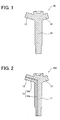
- FIG. 1 is a longitudinal sectional view showing a schematic structure of a body structure 10 before a passage is formed in an injector body.
- FIG. 2 is a longitudinal sectional view showing a schematic structure of a body 10A in which a passage 14 is formed in the body structure 10.
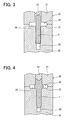
- FIG. 3 to FIG. 5 are sectional views showing respective steps that show a method for forging the body structure 10 and including a die 20.
- a main body portion 11 that is nearly shaped like a circular column which extends in the up and down directions in the drawing having an inclined stepped portion formed at a middle portion, and a pair of side arm portions (side branch portions) 12, 13 that branch from the main body portion 11 extending to the sides upward in the drawing, are formed integrally with each other.
- the body structure 10 is formed of steel (SCM 415 in this embodiment) and is formed in the shape shown in FIG. 1. Then, a passage 14 for passing high-pressure fuel is drilled as shown in FIG. 2, thereby the body structure 10 is formed into the body 10A.
- the die 20 is a closed forging die constructed of an upper die 21, a lower die 22, and a punch 23.
- the punch 23 of this embodiment is provided in the upper die 21 and is so constructed as to be able to move back and forth toward a die space (product portion) 24 of a closed space formed when the upper die 21 and the lower die 22 are matched with each other.
- the die space 24 is formed by a forward extrusion portion 25 extending in the up and down directions in the drawing and by a pair of side extrusion portions 26, 27 branching from the forward extrusion portion 25 and extending in the left and right directions (i.e., directions perpendicular to a direction in which the forward extrusion portion 25 extends) in the drawing.
- the pair of side extrusion portions 26, 27 are formed at symmetric positions across the forward extrusion portion 25 (positions symmetric with respect to the axis of the forward extrusion portion 25). That is, the two extrusion portions 26, 27 are arranged equally in the circumferential direction of the axis of the forward extrusion portions 25.
- the upper die 21 and the lower die 22 are matched to each other to confine a billet 1 of a raw material in the forward extrusion portion 25 of the die space 24.
- This billet 1 is a circular column-shaped member made of the above-mentioned steel (SCM 415 in this embodiment) and is prepared by cutting a round bar in a specified length by a billet shear or the like.
- this billet 1 has an outside diameter that is a little smaller than the inside diameter of the forward extrusion portion 25 (specifically, inside diameter of a middle portion in the up and down directions in the drawing) and hence can be easily inserted into an elongated hole forming the forward extrusion portion 25. Then, after the billet 1 is inserted into the elongated hole, the axis of the billet 1 can be easily consistent with the axis of the forward extrusion portion 25.
- the punch 23 is moved down, thereby being pressed into the billet 1.
- the billet 1 is plastically deformed downward in the forward extrusion portion 25 and is plastically deformed to the sides in the side extrusion portions 26, 27.
- the plastic deformation proceeds to bring about a state where the material forming the billet 1 (i.e., material to be processed) nearly fills the die space 24, whereby the body structure 10 is formed.
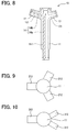
- the upper die 21 and the lower die 22 are opened and a forged body is separated from the dies, whereby the body structure 10 whose longitudinal sectional view is shown in FIG. 6 and whose perspective view is shown in FIG. 7 can be obtained.
- This body structure 10 is constructed with the main body portion 11 plastically deformed in correspondence with the forward extrusion portion 25 of the die space 24 and side arm portions 12, 13 plastically deformed in correspondence with the side extrusion portions 26, 27. That is, the body structure 10 is constructed of the main body portion 11 extending in one direction (in the up and down directions in FIG. 6) and the pair of side arm portions 12, 13.
- the side arm portions 12, 13 branch from the main body portion 11, extend in a direction perpendicular to a direction in which the main body portion 11 extends, and are arranged at symmetric positions with respect to the main body portion 11.
- the step shown in FIG. 3 is an arranging step in the present embodiment, and steps shown in FIG. 4 and FIG. 5 show a forming step in the present embodiment.
- the billet 1 arranged in the die space 24 in the arranging step shown in FIG. 3 is heated to a temperature range between 750 °C and 800 °C. It is preferable that the temperature of the billet 1 forged in the present embodiment is between 600 °C and 950 °C.
- the temperature of the billet 1 is preferably in a range between 600 °C and 950 °C, and more preferably in a range between 750 °C and 800 °C.
- Both the side arm portions 12, 13 of the body structure 10 formed in this manner are bent upward in FIG. 6 by pressing or the like to produce the substantial body structure 10 shown in FIG. 1.
- the body structure 10 shown in FIG. 1 is subjected to normalizing work and then has a passage 14 formed by drilling or the like to form a body 10A shown in FIG. 2.
- the body 10A is subjected to carburizing and hardening work. Then, other injector constituent parts are assembled therewith.
- the billet 1 arranged in the die space 24 is prepared by cutting a round bar and has a fiber flow in the up and down directions shown in FIG. 3.
- the material to be processed is plastically deformed downward in the drawing in the forward extrusion portion 25 and hence a fiber flow extending in the up and down directions is formed. Because a fiber flow extending in the up and down directions is already formed in the billet 1 before the billet 1 is plastically deformed, a stable fiber flow is easily formed in the up and down directions (i.e., directions in which the forward extrusion portion 25 extends) in the forward extrusion portion 25.
- both side extrusion portions 26, 27 extend nearly in directions perpendicular to the axial direction (i.e., extending direction) of the forward extrusion portion 25, the material to be processed is plastically deformed with stability from the forward extrusion portion 25 to both the side extrusion portions 26, 27.
- a stable fiber flow is formed in the directions in which the side extrusion portions 26, 27 extend.
- both the side extrusion portions 26, 27 branch from the forward extrusion portion 25 at symmetric positions (positions at equal distances in the circumferential direction of the axis) on the same height positions in the axial direction of the forward extrusion portion 25. Therefore, when the material to be processed is plastically deformed in the side extrusion portions 26, 27, the material to be processed enters from the forward extrusion portion 25 into both the side extrusion portions 26, 27 in good balance and hence does not disturb the fiber flow of the material to be processed at the points where the side extrusion portions 26, 27 branch from the forward extrusion portion 25.
- a fiber flow 111 is formed in the main body portion 11 in directions shown by broken lines along the direction in which the main body portion 11 extends and fiber flows 121, 131 are formed in the side arm portions 12, 13 in directions shown by broken lines along the directions in which the side arm portions 12, 13 extend.
- a passage 14a is formed in the main body portion 11 in the direction in which the main body portion 11 extends and a passage 14b is formed in the side arm portion 12 in the direction in which the side arm portion 12 extends.
- the fiber flow 111 along the passage 14a is formed in the main body portion 11, and the fiber flow 121 along the passage 14b is formed in the side arm portion 12.
- the fiber flows 111, 121 are along the passage 14 (i.e., passage 14a and passage 14b) formed in the main body portion 11 and the side arm portion 12 of the body structure 10.
- the direction in which stress is applied to the passage 14 by an internal pressure due to the high-pressure fuel is approximately perpendicular to the directions of the fiber flows 111, 121.
- the direction in which stress is applied to the passage 14 by the internal pressure is nearly perpendicular to the directions of the fiber flows 111, 121 and hence the degree of allowance of the resistance to pressure of the body 10A for the injector can be increased.
- the present inventors conducted the test of applying internal pressure repetitively on the body structure 10 manufactured by the present embodiment and on the body structure 110 manufactured by the forging method shown in FIG. 11B and found that pressure resistance strength was approximately 10 % larger in the body structure 10 manufactured by the present embodiment than in body structure 110 manufactured by the method shown in FIG. 11B.
- the body 10A for an injector according to the present embodiment in which the main body portion 11 and the side arm portion 12 are integrally formed has an advantage in the reliability of resistance to pressure.
- the flash 103 formed in the method shown in FIG. 11B is not formed and hence material loss can be reduced and the step of trimming the flash 103 can be eliminated.
- a raw material can be set by inserting the billet 1 into the forward extrusion portion 25 and hence such a gripping portion 104 for setting the raw material that is required in the conventional method as shown in FIG. 11B is not required. Therefore, material loss can be further reduced.
- the body structure 10 can be formed with higher accuracy.
- a portion lower than the side arm portions 12, 13 of the main body portion 11 of the body structure 10 is formed in one depressed space of the lower die 22 and hence can be formed with extremely high accuracy. Therefore, this can eliminate the need for cutting its outer peripheral surface and hence can reduce load in post-working by a large amount.
- the passage 14 when the passage 14 is formed in the body structure 10 by drilling, a drill is moved along the fiber flows 111, 121 and hence can be accurately moved in a straight line. Therefore, the passage 14 can be also formed with high accuracy.
- the side extrusion portions 26, 27 in the die space 24 are formed at the symmetric positions across the forward extrusion portion 25. That is, the side extrusion portions 26, 27 in the die space 24 are formed at symmetric positions with respect to the axis of the forward extrusion portion 25.
- the body structure 10, constructed of the main body portion 11 extending in the up and down directions and the pair of side arm portions 12, 13 branching from the main body portion 11 and arranged at symmetric positions with respect to the main body portion 11, is forged.
- the side extrusion portions of the die space, that is, the side arm portions of the structure to be forged are not limited to two portions but may be three or more portions.
- the body structure 10 may have a plurality of side arm portions 212 (e.g., three arm portions in Fig. 3) formed at equal intervals in the circumferential direction of the axis of the main body portion 11. Also in this case, the material to be processed enters from the forward extrusion portion into three side extrusion portions uniformly (in good balance) and hence the fiber flow of the material to be processed is not disturbed at the points where the side arm portions 212 branch from the main body portion 11.
- side arm portions 212 e.g., three arm portions in Fig. 3
- the material to be processed enters from the forward extrusion portion into three side extrusion portions uniformly (in good balance) and hence the fiber flow of the material to be processed is not disturbed at the points where the side arm portions 212 branch from the main body portion 11.
- the material to be processed enters in good balance from the forward extrusion portion into a plurality of side extrusion portions, for example, even if the side arm portions 312 branch from the main body portion 11 as shown by the top plan view in FIG. 10, the fiber flow of the material to be processed is not disturbed at the points where the side arm portions 312 branch from the main body portion 11.
- the die 20 is divided into the upper and lower dies 21, 22 and the punch 23 is provided on the side of the upper die 21.
- the structure of the die may be of the type in which the die is divided into left and right dies or of the type in which the die is divided into three parts.
- the die may be provided with a plurality of punches.
- the forward extrusion of forming the main body portion 11 and the side extrusion of forming the side arm portions 12, 13 are performed at the same time, but they may be performed separately. It is also recommended that after the forward extrusion is performed, the side extrusion can be performed.
- the material to be processed of the billet 1 is SCM415 but may be other material.
- the material to be processed may be steel such as S45C or SCM435.
- the high-pressure piping part forged in the closed space is the injector body structure for the internal combustion engine (diesel engine) but the present invention can be effectively applied to the other high-pressure piping parts.
- the present invention may be applied to a common rail for distributing and supplying fuel to an injector and may be applied to piping parts for passing other high-pressure fluid.
- the shape of the high-pressure piping part is not limited to the structure constructed of the main portion and the side arm portion.
- a high-pressure piping part includes a body structure (10) forged in a closed space (24).
- the body structure (10) is formed to include a main body portion (11) formed by forward extrusion and side arm portions (12, 212, 312) formed by side extrusion.
- the main body portion (11) has therein a fiber flow (111) formed along a passage, and the side arm portion has therein a fiber flow (121) formed along the passage. Therefore, the direction in which stress is applied to the passage of the body structure by an internal pressure is approximately perpendicular to the directions of the fiber flows, thereby improving the degree of allowance of the resistance to pressure of the body structure for an injector.
Landscapes
- Engineering & Computer Science (AREA)
- Mechanical Engineering (AREA)
- Manufacturing & Machinery (AREA)
- Chemical & Material Sciences (AREA)
- Combustion & Propulsion (AREA)
- General Engineering & Computer Science (AREA)
- Forging (AREA)
- Fuel-Injection Apparatus (AREA)
Abstract
Description
- The present invention relates to a method for manufacturing a high-pressure piping part and a high-pressure piping part manufactured by the method and, in particular, is suitably applied to a high-pressure piping part for an internal combustion engine.
- For example, a high-pressure piping part having therein a passage for passing high-pressure fuel to be supplied to an internal combustion engine is a constituent part for forming a body of an injector for a diesel engine.
- Generally, in a case of manufacturing this piping part, because of convenience in terms of equipment, a
billet 101 shaped like a circular column shown in FIG. 11A is forged in a radial direction in a half closed manner to form aforged body 102 as shown in FIG. 11B. Then, a flash (burr) 103 and the like are trimmed to form abody structure 110. Then, a passage for passing high-pressure fuel is formed in thisbody structure 110. - The fuel flowing through the passage of this injector body has a very high pressure (for example, pressure of 180 MPa) and hence a large degree of allowance is provided to the resistance to pressure of the injector body.
- In recent years, in order to respond to a trend toward larger power and cleaner exhaust gas of a diesel engine, the pressure of fuel to be supplied has been desired to be further increased. However, it is difficult to further improve the resistance to pressure of the injector body of a high-pressure piping part manufactured by the above-mentioned manufacturing method in the related art. Hence, there is presented a problem that it is difficult to secure the same degree of allowance of the resistance to pressure as ever.
- The present inventors earnestly studied measures to improve the degree of allowance of the resistance to pressure of a body structure. As a result, the present inventors found that the fracture of the body structure in a high internal pressure test for checking the degree of allowance of resistance to pressure easily developed when the direction in which stress was applied to the body structure by the internal pressure agreed with the direction of fiber flow of the body structure. That is, the present inventors found that by controlling the fiber flow, the degree of allowance of the resistance to pressure of an injector body of a high-pressure piping part could be improved.
- In view of the above-described problems, it is an object of the present invention to provide a method for manufacturing a piping part for a high-pressure fluid, in which a degree of allowance of resistance to pressure is improved.
- It is another object of the present invention to provide a piping part for a high-pressure fluid, which can effectively improve a degree of allowance of resistance to pressure.
- According to the present invention, a method for manufacturing a piping part for a high-pressure fluid, includes a step of arranging a billet made of a raw material in a closed space within a die, and a step of forming a body structure before a passage for the high-pressure fluid is formed by pressing a punch to the billet after the arranging step to plastically deform the billet. Further, in the forming step, the billet is plastically deformed in such a way that fiber flows along the passage are formed in the body structure.
- Because the fiber flows of the body structure forged in the closed space is along the passage for the high-pressure fluid, the direction in which stress is applied to the passage by an internal pressure is approximately perpendicular to the directions of the fiber flows. In this manner, the degree of allowance of the resistance to pressure of the body structure can be effectively improved in the piping part.
- For example, the closed space within the die includes a forward extrusion portion in which the billet is arranged in the arranging step and which extends to plastically deform the billet in a pressing direction of the punch in the forming step, and a side extrusion portion branching from the forward extrusion portion in such a way as to plastically deform the billet in a direction different from the pressing direction of the punch in the forming step. In this case, in the forming step, the body structure is formed to include a main portion that is plastically deformed in correspondence with the forward extrusion portion and has therein the fiber flow along the passage, and a side arm portion that is plastically deformed in correspondence with the side extrusion portion and has therein the fiber flow along the passage. Therefore, the body structure having the main portion and the side arm portion branching from the main portion can improve the degree of allowance of the resistance to pressure of the high-pressure piping part.
- The side extrusion portion can be formed to extend in a direction approximately perpendicular to an extending direction in which the forward extrusion portion extends. In this case, during the forming step, the billet in the forward extrusion portion can be easily plastically deformed from the forward extrusion portion to the side extrusion portions. Therefore, the fiber flow along the passage can be stably formed in the side arm portion formed in the side extrusion portion.
- For example, the side extrusion portion includes a plurality of extrusion parts. In this case, in the forming step, the billet can be plastically deformed in balance in a circumferential direction of an axis of the forward extrusion portion from the forward extrusion portion to the plurality of extrusion parts. According to this, the plastically deformed portions of the billet entering from the forward extrusion portion into the plurality of side extrusion portions are in balance in the circumferential direction of the axis of the forward extrusion portion and hence the fiber flow of the main portion formed in the forward extrusion portion is not disturbed. Therefore, the fiber flow along the passage can be stably formed in the main portion of the body structure. Alternatively, the plurality of extrusion parts can be arranged at equal intervals in the circumferential direction of the axis of the forward extrusion portion. In this case, the fiber flow along the passage can be stably formed in the main portion of the body structure having the side arm portions.
- Furthermore, the billet arranged in the forward extrusion portion in the arranging step is provided with a fiber flow in the pressing direction of the punch. In this case, it is extremely easy to stably form the fiber flow along the passage in the main portion of the body structure.
- According to another aspect of the present invention, a piping part for a high-pressure fluid includes a body structure forged in a closed space, and the body structure includes a passage through which the high-pressure fluid flows and a plurality of fiber flows provided along the passage. Therefore, it is possible to improve the degree of allowance of the resistance to pressure of the high-pressure piping part. The body structure can include a main portion extending in an extending direction, and a side arm portion branching from the main portion and extending in a directions different from the extending direction of the main portion. In this case, the fiber flows along the passage can be provided in the main portion and the side arm portion.
- In the present invention, the high-pressure fluid can be suitably used as fuel for an internal combustion engine.
- The above and other objects, features and advantages of the present invention will become more apparent from the following detailed description of preferred embodiments made with reference to the accompanying drawings, in which:
- FIG. 1 is a schematic longitudinal sectional view showing a body structure of a high-pressure piping part in a preferred embodiment to which the present invention is applied;
- FIG. 2 is a schematic longitudinal sectional view showing a body having a passage formed in the body structure;
- FIG. 3 is a sectional view showing a step for forging the body structure;
- FIG. 4 is a sectional view showing a step for forging the body structure;
- FIG. 5 is a sectional view showing a step for forging the body structure;
- FIG. 6 is a schematic longitudinal sectional view showing the body structure separated from a die;
- FIG. 7 is a schematic perspective view showing the body structure separated from the die;
- FIG. 8 is a schematic diagram showing the direction of the fiber flow of the body structure;
- FIG. 9 is a top plan view showing a body structure according to a modification of the present invention;
- FIG. 10 is a top plan view showing a body structure according to another modification of the present invention;
- FIGs. 11A and 11B are diagrams showing a method for forming a body structure by a half-closed forging in a related art; and
- FIG. 12 is a diagram showing the direction of the fiber flow of a body structure according to the method in FIGs. 11A and 11B.
- Preferred embodiments of the present invention will be described with reference to the drawings.
- A high-pressure piping part in an embodiment is a body of an injector for injecting high-pressure fuel (for example, light oil of a pressure of 200 MPa) into a diesel engine of an internal combustion engine.
- FIG. 1 is a longitudinal sectional view showing a schematic structure of a
body structure 10 before a passage is formed in an injector body. FIG. 2 is a longitudinal sectional view showing a schematic structure of abody 10A in which apassage 14 is formed in thebody structure 10. Then, FIG. 3 to FIG. 5 are sectional views showing respective steps that show a method for forging thebody structure 10 and including adie 20. - As shown in FIG. 1, in the
body structure 10, amain body portion 11 that is nearly shaped like a circular column which extends in the up and down directions in the drawing having an inclined stepped portion formed at a middle portion, and a pair of side arm portions (side branch portions) 12, 13 that branch from themain body portion 11 extending to the sides upward in the drawing, are formed integrally with each other. - The
body structure 10 is formed of steel (SCM 415 in this embodiment) and is formed in the shape shown in FIG. 1. Then, apassage 14 for passing high-pressure fuel is drilled as shown in FIG. 2, thereby thebody structure 10 is formed into thebody 10A. - Next, a method for forging the
body structure 10 using adie 20 will be described. - As shown in FIG. 3, the
die 20 is a closed forging die constructed of anupper die 21, alower die 22, and apunch 23. Thepunch 23 of this embodiment is provided in theupper die 21 and is so constructed as to be able to move back and forth toward a die space (product portion) 24 of a closed space formed when theupper die 21 and thelower die 22 are matched with each other. - The
die space 24 is formed by aforward extrusion portion 25 extending in the up and down directions in the drawing and by a pair ofside extrusion portions forward extrusion portion 25 and extending in the left and right directions (i.e., directions perpendicular to a direction in which theforward extrusion portion 25 extends) in the drawing. - The pair of
side extrusion portions extrusion portions forward extrusion portions 25. - When the
body structure 10 is manufactured by the use of the die 20 constructed in the above-described manner, as shown in FIG. 3, theupper die 21 and thelower die 22 are matched to each other to confine a billet 1 of a raw material in theforward extrusion portion 25 of thedie space 24. - This billet 1 is a circular column-shaped member made of the above-mentioned steel (SCM 415 in this embodiment) and is prepared by cutting a round bar in a specified length by a billet shear or the like.
- Moreover, this billet 1 has an outside diameter that is a little smaller than the inside diameter of the forward extrusion portion 25 (specifically, inside diameter of a middle portion in the up and down directions in the drawing) and hence can be easily inserted into an elongated hole forming the
forward extrusion portion 25. Then, after the billet 1 is inserted into the elongated hole, the axis of the billet 1 can be easily consistent with the axis of theforward extrusion portion 25. - When the billet 1 is arranged in the
die space 24 of the die 20, as shown in FIG. 4, thepunch 23 is moved down, thereby being pressed into the billet 1. When thepunch 23 is pressed into the billet 1, the billet 1 is plastically deformed downward in theforward extrusion portion 25 and is plastically deformed to the sides in theside extrusion portions - When the
punch 23 is further pressed into the billet 1, as shown in FIG. 5, the plastic deformation proceeds to bring about a state where the material forming the billet 1 (i.e., material to be processed) nearly fills thedie space 24, whereby thebody structure 10 is formed. - When the forging is completed as shown in FIG. 5, the
upper die 21 and thelower die 22 are opened and a forged body is separated from the dies, whereby thebody structure 10 whose longitudinal sectional view is shown in FIG. 6 and whose perspective view is shown in FIG. 7 can be obtained. - This
body structure 10 is constructed with themain body portion 11 plastically deformed in correspondence with theforward extrusion portion 25 of thedie space 24 andside arm portions side extrusion portions body structure 10 is constructed of themain body portion 11 extending in one direction (in the up and down directions in FIG. 6) and the pair ofside arm portions side arm portions main body portion 11, extend in a direction perpendicular to a direction in which themain body portion 11 extends, and are arranged at symmetric positions with respect to themain body portion 11. - The step shown in FIG. 3 is an arranging step in the present embodiment, and steps shown in FIG. 4 and FIG. 5 show a forming step in the present embodiment.
- Here, the billet 1 arranged in the
die space 24 in the arranging step shown in FIG. 3 is heated to a temperature range between 750 °C and 800 °C. It is preferable that the temperature of the billet 1 forged in the present embodiment is between 600 °C and 950 °C. - When the temperature of the billet 1 is lower than 600 °C, ductility is little and hence forging is difficult. When the temperature of the billet 1 is higher than 950 °C, forging accuracy becomes lower. From the viewpoint of the ease of forging and forging accuracy, the temperature of the billet 1 is preferably in a range between 600 °C and 950 °C, and more preferably in a range between 750 °C and 800 °C.
- Both the
side arm portions body structure 10 formed in this manner are bent upward in FIG. 6 by pressing or the like to produce thesubstantial body structure 10 shown in FIG. 1. - The
body structure 10 shown in FIG. 1 is subjected to normalizing work and then has apassage 14 formed by drilling or the like to form abody 10A shown in FIG. 2. Thebody 10A is subjected to carburizing and hardening work. Then, other injector constituent parts are assembled therewith. - Here, the formation of a fiber flow in the forging step shown in FIG. 3 to FIG. 5 will be described.
- In FIG. 3, the billet 1 arranged in the
die space 24 is prepared by cutting a round bar and has a fiber flow in the up and down directions shown in FIG. 3. - When the billet 1 is being plastically deformed in the manner shown in FIG. 4 and FIG. 5, the material to be processed is plastically deformed downward in the drawing in the
forward extrusion portion 25 and hence a fiber flow extending in the up and down directions is formed. Because a fiber flow extending in the up and down directions is already formed in the billet 1 before the billet 1 is plastically deformed, a stable fiber flow is easily formed in the up and down directions (i.e., directions in which theforward extrusion portion 25 extends) in theforward extrusion portion 25. - Meanwhile, because the material to be processed is plastically deformed in the left and right directions in the drawing in the
side extrusion portions - Because both
side extrusion portions forward extrusion portion 25, the material to be processed is plastically deformed with stability from theforward extrusion portion 25 to both theside extrusion portions side extrusion portions forward extrusion portion 25, a stable fiber flow is formed in the directions in which theside extrusion portions - Moreover, both the
side extrusion portions forward extrusion portion 25 at symmetric positions (positions at equal distances in the circumferential direction of the axis) on the same height positions in the axial direction of theforward extrusion portion 25. Therefore, when the material to be processed is plastically deformed in theside extrusion portions forward extrusion portion 25 into both theside extrusion portions side extrusion portions forward extrusion portion 25. - Hence, as shown in FIG. 8, in the
body structure 10, afiber flow 111 is formed in themain body portion 11 in directions shown by broken lines along the direction in which themain body portion 11 extends and fiber flows 121, 131 are formed in theside arm portions side arm portions - As shown in FIG. 2 and shown by double dot and dash lines in FIG. 8, in the
body structure 10, apassage 14a is formed in themain body portion 11 in the direction in which themain body portion 11 extends and apassage 14b is formed in theside arm portion 12 in the direction in which theside arm portion 12 extends. - That is, the
fiber flow 111 along thepassage 14a is formed in themain body portion 11, and thefiber flow 121 along thepassage 14b is formed in theside arm portion 12. - According to the above-mentioned structure and manufacturing method, in the
main body portion 11 and theside arm portion 12 of thebody structure 10, the fiber flows 111, 121 are along the passage 14 (i.e.,passage 14a andpassage 14b) formed in themain body portion 11 and theside arm portion 12 of thebody structure 10. Hence, the direction in which stress is applied to thepassage 14 by an internal pressure due to the high-pressure fuel is approximately perpendicular to the directions of the fiber flows 111, 121. - When the fiber flows are formed, nonmetallic inclusions such as sulfur and the like causing fatigue fracture in the billet (material to be processed) 1 are stretched along the fiber flows (i.e., flow of the material to be processed). Therefore, fracture strength becomes comparatively larger in a case where the direction in which stress is applied to the
passage 14 by the internal pressure does not agree with the direction of the fiber flow. - According to the present embodiment, the direction in which stress is applied to the
passage 14 by the internal pressure is nearly perpendicular to the directions of the fiber flows 111, 121 and hence the degree of allowance of the resistance to pressure of thebody 10A for the injector can be increased. - When a
body structure 110 is formed by a half-closed forging method shown in FIG. 11B, as shown by broken lines with arrows in FIG. 12, fiber flows are formed from thebody structure 110 toward aflash 103 and hence the direction in which stress is applied to thepassage 114 by the internal pressure (direction shown by a solid line with arrows) easily agree with the directions of the fiber flows. - The present inventors conducted the test of applying internal pressure repetitively on the
body structure 10 manufactured by the present embodiment and on thebody structure 110 manufactured by the forging method shown in FIG. 11B and found that pressure resistance strength was approximately 10 % larger in thebody structure 10 manufactured by the present embodiment than inbody structure 110 manufactured by the method shown in FIG. 11B. - In recent years, the request of increasing the pressure of fuel supplied to an internal combustion engine has increased and hence the effect of increasing the degree of allowance of the resistance to pressure of the
body 10A for the injector is extremely large. - It is possible to form the main portion and the side arm portion from separate parts and to combine them into one part by a fastening structure by screwing to form a body for an injector in which a fiber flow is along the passage. However, in this case, when the fuel pressure increases, it is difficult to secure the reliability of the resistance to pressure of portions fastened to each other by screwing. The
body 10A for an injector according to the present embodiment in which themain body portion 11 and theside arm portion 12 are integrally formed has an advantage in the reliability of resistance to pressure. - Moreover, according to the structure and the manufacturing method of the present embodiment, the
flash 103 formed in the method shown in FIG. 11B is not formed and hence material loss can be reduced and the step of trimming theflash 103 can be eliminated. - Furthermore, a raw material can be set by inserting the billet 1 into the
forward extrusion portion 25 and hence such agripping portion 104 for setting the raw material that is required in the conventional method as shown in FIG. 11B is not required. Therefore, material loss can be further reduced. - Still furthermore, in contrast to the case of applying the conventional method, the
body structure 10 can be formed with higher accuracy. In particular, a portion lower than theside arm portions main body portion 11 of thebody structure 10 is formed in one depressed space of thelower die 22 and hence can be formed with extremely high accuracy. Therefore, this can eliminate the need for cutting its outer peripheral surface and hence can reduce load in post-working by a large amount. - Still furthermore, when the
passage 14 is formed in thebody structure 10 by drilling, a drill is moved along the fiber flows 111, 121 and hence can be accurately moved in a straight line. Therefore, thepassage 14 can be also formed with high accuracy. - Although the present invention has been described in connection with the preferred embodiment thereof with reference to the accompanying drawings, it is to be noted that various changes and modifications will become apparent to those skilled in the art.
- For example, in the above-mentioned embodiment, the
side extrusion portions die space 24 are formed at the symmetric positions across theforward extrusion portion 25. That is, theside extrusion portions die space 24 are formed at symmetric positions with respect to the axis of theforward extrusion portion 25. Furthermore, thebody structure 10, constructed of themain body portion 11 extending in the up and down directions and the pair ofside arm portions main body portion 11 and arranged at symmetric positions with respect to themain body portion 11, is forged. However, the side extrusion portions of the die space, that is, the side arm portions of the structure to be forged are not limited to two portions but may be three or more portions. - For example, as shown by the top plan view in FIG. 9, the
body structure 10 may have a plurality of side arm portions 212 (e.g., three arm portions in Fig. 3) formed at equal intervals in the circumferential direction of the axis of themain body portion 11. Also in this case, the material to be processed enters from the forward extrusion portion into three side extrusion portions uniformly (in good balance) and hence the fiber flow of the material to be processed is not disturbed at the points where theside arm portions 212 branch from themain body portion 11. - Moreover, when the material to be processed enters in good balance from the forward extrusion portion into a plurality of side extrusion portions, for example, even if the
side arm portions 312 branch from themain body portion 11 as shown by the top plan view in FIG. 10, the fiber flow of the material to be processed is not disturbed at the points where theside arm portions 312 branch from themain body portion 11. - Furthermore, in the above-mentioned embodiment, the
die 20 is divided into the upper and lower dies 21, 22 and thepunch 23 is provided on the side of theupper die 21. However, it is not intended to limit the structure of the die to this but any structure may be employed if a material to be processed can be forged in a closed space. For example, the structure of the die may be of the type in which the die is divided into left and right dies or of the type in which the die is divided into three parts. In addition, the die may be provided with a plurality of punches. - Still furthermore, in the above-mentioned embodiment, the forward extrusion of forming the
main body portion 11 and the side extrusion of forming theside arm portions - Still furthermore, in the above-mentioned embodiment, the material to be processed of the billet 1 is SCM415 but may be other material. For example, the material to be processed may be steel such as S45C or SCM435.
- Still furthermore, in the above-mentioned embodiment, the high-pressure piping part forged in the closed space is the injector body structure for the internal combustion engine (diesel engine) but the present invention can be effectively applied to the other high-pressure piping parts.
- For example, the present invention may be applied to a common rail for distributing and supplying fuel to an injector and may be applied to piping parts for passing other high-pressure fluid. In addition, the shape of the high-pressure piping part is not limited to the structure constructed of the main portion and the side arm portion.
- While the invention has been described with reference to preferred embodiments thereof, it is to be understood that the invention is not limited to the preferred embodiments and constructions. The invention is intended to cover various modification and equivalent arrangements. In addition, while the various elements of the preferred embodiments are shown in various combinations and configurations, which are preferred, other combinations and configuration, including more, less or only a single element, are also within the spirit and scope of the invention.
- A high-pressure piping part includes a body structure (10) forged in a closed space (24). The body structure (10) is formed to include a main body portion (11) formed by forward extrusion and side arm portions (12, 212, 312) formed by side extrusion. The main body portion (11) has therein a fiber flow (111) formed along a passage, and the side arm portion has therein a fiber flow (121) formed along the passage. Therefore, the direction in which stress is applied to the passage of the body structure by an internal pressure is approximately perpendicular to the directions of the fiber flows, thereby improving the degree of allowance of the resistance to pressure of the body structure for an injector.
Claims (16)
- A method for manufacturing a piping part for a high-pressure fluid, the method comprising the steps of:arranging a billet (1) made of a raw material in a closed space (24) within a die (20); andforming a body structure (10) before a passage (14) for the high-pressure fluid is formed, by pressing a punch (23) to the billet (1) after the arranging step to plastically deform the billet (1), wherein:in the forming step, the billet (1) is plastically deformed in such a way that fiber flows (111, 121) along the passage (14) are formed in the body structure (10).
- The method for manufacturing a piping part as in claim 1, wherein:the closed space (24) within the die (20) includes
a forward extrusion portion (25) in which the billet (1) is arranged in the arranging step and which extends to plastically deform the billet (1) in a pressing direction of the punch (23) in the forming step, and
a side extrusion portion (26, 27) branching from the forward extrusion portion (25) in such a way as to plastically deform the billet (1) in a direction different from the pressing direction of the punch in the forming step; andin the forming step, the body structure (10) is formed to include a main portion (11) that is plastically deformed in correspondence with the forward extrusion portion and has therein the fiber flow along the passage (14a), and a side arm portion (12, 212, 312) that is plastically deformed in correspondence with the side extrusion portion (26, 27) and has therein the fiber flow along the passage (14b). - The method for manufacturing a piping part as in claim 2, wherein the side extrusion portion (26, 27) extends in a direction approximately perpendicular to an extending direction in which the forward extrusion portion (25) extends.
- The method for manufacturing a piping part as in claim 2 or 3, wherein:the side extrusion portion includes a plurality of extrusion parts (26, 27); andin the forming step, the billet (1) is plastically deformed in balance in a circumferential direction of an axis of the forward extrusion portion (25) from the forward extrusion portion (25) to the plurality of extrusion parts (26, 27).
- The method for manufacturing a piping part as in any one of claims 2-4, wherein:the side extrusion portion includes a plurality of extrusion parts (26, 27); andthe plurality of extrusion parts (26, 27) are arranged at equal intervals in a circumferential direction of an axis of the forward extrusion portion.
- The method for manufacturing a piping part as in any one of claims 2-5, wherein the fiber flows (111) are formed in the pressing direction of the punch in the billet (1) arranged in the forward extrusion portion in the arranging step.
- The method for manufacturing a piping part as in claim 2, further comprising
forming the passage (14) including a first passage part (14a) provided in the main portion (11) and a second passage part (14b) provided in the side arm portion (12), by drilling; and
the drilling is performed by moving a drill along the fiber flows after the fiber flows are formed. - The method for manufacturing a piping part as in claim 7, further comprising
bending the side arm portion (12, 212, 312) by pressing. - The method for manufacturing a piping part as in claim 2, wherein:in the forming step, the pressing is performed while heating the billet (1) in a temperature range of 600 °C - 950 °C.
- The method for manufacturing a piping part as in claim 9, wherein:in the forming step, the pressing is performed while heating the billet (1) in a temperature range of 750 °C - 800 °C.
- The method for manufacturing a piping part as in any one of claims 1-10, wherein the high-pressure fluid is fuel for an internal combustion engine.
- A piping part for a high-pressure fluid, comprising:a body structure (10) forged in a closed space (24), wherein the body structure (10) includes a passage (14) through which the high-pressure fluid flows, and a plurality of fiber flows (111, 121) provided along the passage.
- The piping part as in claim 12, wherein:the body structure (10) includes a main portion (11) extending in an extending direction, and a side arm portion (12, 212, 312) branching from the main portion and extending in a directions different from the extending direction of the main portion; andthe fiber flows (111, 121) along the passage are provided in the main portion and the side arm portion.
- The piping part as in claim 13, wherein the side arm portion extends in a direction approximately perpendicular to the extending direction of the main portion.
- The piping part as in claim 13, wherein:the side arm portion includes a plurality of arm parts (12, 13, 212); andthe plurality of arm parts are arranged at equal intervals in a circumferential direction of an axis of the main portion.
- The piping part as in any one of claims 12-15, wherein the high-pressure fluid is fuel for an internal combustion engine.
Applications Claiming Priority (1)
| Application Number | Priority Date | Filing Date | Title |
|---|---|---|---|
| JP2004374696A JP2006181577A (en) | 2004-12-24 | 2004-12-24 | High pressure piping parts manufacturing method and high pressure piping parts |
Publications (2)
| Publication Number | Publication Date |
|---|---|
| EP1674172A1 true EP1674172A1 (en) | 2006-06-28 |
| EP1674172B1 EP1674172B1 (en) | 2008-02-27 |
Family
ID=36177974
Family Applications (1)
| Application Number | Title | Priority Date | Filing Date |
|---|---|---|---|
| EP05027001A Expired - Lifetime EP1674172B1 (en) | 2004-12-24 | 2005-12-09 | Method for manufacturing high-pressure piping part and structure thereof |
Country Status (5)
| Country | Link |
|---|---|
| US (1) | US7219524B2 (en) |
| EP (1) | EP1674172B1 (en) |
| JP (1) | JP2006181577A (en) |
| CN (1) | CN100513001C (en) |
| DE (1) | DE602005004996T2 (en) |
Cited By (1)
| Publication number | Priority date | Publication date | Assignee | Title |
|---|---|---|---|---|
| DE102007015222A1 (en) | 2007-03-05 | 2008-09-11 | Hirschvogel Umformtechnik Gmbh | Machining of workpieces to improve the material properties |
Families Citing this family (8)
| Publication number | Priority date | Publication date | Assignee | Title |
|---|---|---|---|---|
| CN1989352B (en) * | 2004-09-08 | 2011-08-17 | Ntn株式会社 | Shaft member for fluid bearing device and its manufacturing method |
| CN100400192C (en) * | 2006-11-09 | 2008-07-09 | 上海锅炉厂有限公司 | A Forging Method of Large Slanted Tee |
| JP4869968B2 (en) * | 2007-02-02 | 2012-02-08 | Ntn株式会社 | Closed forging die and forging method |
| LU91453B1 (en) * | 2008-06-06 | 2009-12-07 | Wurth Paul Sa | Method for manufacturing a cooling plate for a metallurgical furnace |
| CN101574778B (en) * | 2009-06-09 | 2010-08-04 | 上海昌强电站配件有限公司 | Process of integrally shaping U-shaped bifurcated pipe |
| CN104209437B (en) * | 2014-09-02 | 2016-06-01 | 许崇霞 | High-pressure common rail Preform Die |
| JP6969129B2 (en) | 2017-03-23 | 2021-11-24 | 株式会社デンソー | Manufacturing method of piping parts |
| JP6969128B2 (en) | 2017-03-23 | 2021-11-24 | 株式会社デンソー | Piping parts manufacturing method and piping parts manufacturing equipment |
Citations (4)
| Publication number | Priority date | Publication date | Assignee | Title |
|---|---|---|---|---|
| US4305273A (en) * | 1979-12-10 | 1981-12-15 | United States Steel Corporation | Method for forging large irregular shapes in a closed-die operation in a conventional open-die press |
| DE29521402U1 (en) * | 1995-12-23 | 1997-04-24 | Robert Bosch Gmbh, 70469 Stuttgart | Fuel injection system |
| US6223726B1 (en) * | 1996-06-30 | 2001-05-01 | Robert Bosch Gmbh | High pressure fuel reservoir |
| US6470855B1 (en) * | 1999-08-11 | 2002-10-29 | Robert Bosch Gmbh | High-pressure fuel reservoir for a fuel injection system for internal combustion engines |
Family Cites Families (26)
| Publication number | Priority date | Publication date | Assignee | Title |
|---|---|---|---|---|
| US4580432A (en) * | 1982-10-07 | 1986-04-08 | C.L.B. Enterprises, Inc. | Method of making a metal cruciform journal forging |
| US4768369A (en) * | 1987-11-13 | 1988-09-06 | Johnson Russell H | Method of forming a pipe fitting |
| JPH01317649A (en) * | 1988-06-17 | 1989-12-22 | Miyama Tool Kk | Production of core base body for injector |
| JPH01228633A (en) * | 1988-03-07 | 1989-09-12 | Susumu Ito | Manufacture of joint and its main forming die |
| JPH0259136A (en) * | 1988-08-23 | 1990-02-28 | Suzuhide Kogyo Kk | Upsetting forming method for axial body with flange |
| JPH0263635A (en) * | 1988-08-30 | 1990-03-02 | Aida Eng Ltd | Manufacture of flange member |
| JPH0685957B2 (en) * | 1988-12-27 | 1994-11-02 | ミヤマ精工株式会社 | Manufacturing method of body for injector |
| WO1992020475A1 (en) * | 1991-05-16 | 1992-11-26 | Aeroquip Corporation | Precision forming apparatus, method and article |
| JPH05104191A (en) * | 1991-10-15 | 1993-04-27 | Suzuhide Kogyo Kk | Cold forging method for shaft body with flange |
| US5472142A (en) * | 1992-08-11 | 1995-12-05 | Nippondenso Co., Ltd. | Accumulator fuel injection apparatus |
| JP3256885B2 (en) * | 1993-02-16 | 2002-02-18 | 大同特殊鋼株式会社 | Long steel forging method |
| JPH0732080A (en) * | 1993-07-16 | 1995-02-03 | Japan Steel Works Ltd:The | Mold forging product forming method and apparatus |
| JP2517527B2 (en) * | 1993-09-10 | 1996-07-24 | 株式会社メタルアート | Manufacturing method of forged product with shaft |
| JPH08261115A (en) * | 1995-03-27 | 1996-10-08 | Hino Motors Ltd | Fuel passage forming method for nozzle holder in fuel injection nozzle |
| JP3211158B2 (en) * | 1997-12-22 | 2001-09-25 | 株式会社フジユニバンス | Shaft pulley for belt type continuously variable transmission and method of manufacturing the same |
| JPH11280588A (en) * | 1998-03-31 | 1999-10-12 | Denso Corp | Fuel injection nozzle |
| JP2000002356A (en) * | 1998-06-18 | 2000-01-07 | Denso Corp | Solenoid valve and fuel injection valve using the same |
| EP1118765A3 (en) * | 2000-01-19 | 2003-11-19 | CRT Common Rail Technologies AG | Fuel injector for internal combustion engines |
| JP2001212645A (en) * | 2000-02-02 | 2001-08-07 | Daido Steel Co Ltd | Double shaft stand upsetting forging method |
| JP2001321879A (en) * | 2000-05-17 | 2001-11-20 | Toto Ltd | Method and device for manufacturing metallic parts |
| JP2002178080A (en) * | 2000-12-14 | 2002-06-25 | Toto Ltd | Method and device for manufacturing hollow metallic parts |
| JP3928362B2 (en) * | 2001-02-14 | 2007-06-13 | 株式会社デンソー | Structure to improve seal surface pressure of fluid transfer device |
| JP2002263857A (en) * | 2001-03-08 | 2002-09-17 | Nippon Steel Corp | Manufacturing method of metal precision machine parts and metal precision machine parts |
| JP4301767B2 (en) * | 2002-05-31 | 2009-07-22 | 株式会社ユニバンス | Method for forming hollow shaft pulley for belt type continuously variable transmission |
| JP3938891B2 (en) * | 2002-07-17 | 2007-06-27 | 日産自動車株式会社 | Manufacturing method of thrust type ball bearing race |
| JP2004098112A (en) * | 2002-09-09 | 2004-04-02 | Suzuki Motor Corp | Forged piston and manufacturing method thereof |
-
2004
- 2004-12-24 JP JP2004374696A patent/JP2006181577A/en active Pending
-
2005
- 2005-12-09 DE DE602005004996T patent/DE602005004996T2/en not_active Expired - Lifetime
- 2005-12-09 EP EP05027001A patent/EP1674172B1/en not_active Expired - Lifetime
- 2005-12-19 US US11/305,040 patent/US7219524B2/en not_active Expired - Fee Related
- 2005-12-21 CN CNB2005100229721A patent/CN100513001C/en not_active Expired - Fee Related
Patent Citations (4)
| Publication number | Priority date | Publication date | Assignee | Title |
|---|---|---|---|---|
| US4305273A (en) * | 1979-12-10 | 1981-12-15 | United States Steel Corporation | Method for forging large irregular shapes in a closed-die operation in a conventional open-die press |
| DE29521402U1 (en) * | 1995-12-23 | 1997-04-24 | Robert Bosch Gmbh, 70469 Stuttgart | Fuel injection system |
| US6223726B1 (en) * | 1996-06-30 | 2001-05-01 | Robert Bosch Gmbh | High pressure fuel reservoir |
| US6470855B1 (en) * | 1999-08-11 | 2002-10-29 | Robert Bosch Gmbh | High-pressure fuel reservoir for a fuel injection system for internal combustion engines |
Cited By (3)
| Publication number | Priority date | Publication date | Assignee | Title |
|---|---|---|---|---|
| DE102007015222A1 (en) | 2007-03-05 | 2008-09-11 | Hirschvogel Umformtechnik Gmbh | Machining of workpieces to improve the material properties |
| WO2008107045A1 (en) * | 2007-03-05 | 2008-09-12 | Hirschvogel Umformtechnik Gmbh | Machining of workpieces for improving the material properties |
| DE102007015222B4 (en) * | 2007-03-05 | 2017-08-31 | Hirschvogel Umformtechnik Gmbh | Machining of workpieces to improve the material properties |
Also Published As
| Publication number | Publication date |
|---|---|
| JP2006181577A (en) | 2006-07-13 |
| US20060137423A1 (en) | 2006-06-29 |
| CN100513001C (en) | 2009-07-15 |
| CN1792496A (en) | 2006-06-28 |
| DE602005004996D1 (en) | 2008-04-10 |
| DE602005004996T2 (en) | 2009-02-19 |
| US7219524B2 (en) | 2007-05-22 |
| EP1674172B1 (en) | 2008-02-27 |
Similar Documents
| Publication | Publication Date | Title |
|---|---|---|
| EP1674172B1 (en) | Method for manufacturing high-pressure piping part and structure thereof | |
| US10138854B2 (en) | Fuel rail and method of making a fuel rail | |
| US8016214B2 (en) | Fuel injection valve and method for forming orifice thereof | |
| EP2274120B1 (en) | Metal forged crankshaft, apparatus for metal forging a crankshaft and method of metal forging a crankshaft | |
| DE4437395A1 (en) | Method for upsetting pipe ends and device for carrying out the method | |
| CN102884305A (en) | Fuel cup | |
| WO2008003401A1 (en) | Cooling channel piston for an internal combustion engine and method for the production thereof | |
| EP2667011A2 (en) | Method of producing fuel distribution pipe | |
| KR101160446B1 (en) | Injector cup unit for connecting fuel injection pipe and manufacturing method thereof | |
| GB2536103A (en) | Method for producing a composite component | |
| US7125051B2 (en) | Common-rail injection system for diesel engine | |
| DE102008000144B4 (en) | Common rail | |
| CN104210157A (en) | Multi-material joints and methods | |
| DE102017125359B4 (en) | Manufacturing method of a duct component and manufacturing device of a duct component | |
| KR100976081B1 (en) | Manufacturing method of backup ring and sealing structure of backup ring and fuel injection valve | |
| DE102004057558A1 (en) | Piston for internal combustion engine has base component consisting of forged aluminum and ring element of ni-resist, with closed annular cooling passage located between base component and ring element | |
| US20020113150A1 (en) | Component, especially a high-pressure component for fuel injection systems, and method for producing a component of this type | |
| US20210239146A1 (en) | Joining element, connection structure with the joining element, manufacturing method of the joining element and corresponding connection method | |
| US9874184B2 (en) | Internally pressurized component | |
| EP3726047A1 (en) | Rail for high-pressure direct injection | |
| DE102011101770A1 (en) | Assembly has solid body and intersection of high-pressure fluid channel with another high-pressure fluid channel is formed in solid body | |
| CN110905126B (en) | Reinforcement connection sleeve, reinforced concrete column and sleeve processing method | |
| EP2167810B1 (en) | High-pressure fuel accumulator | |
| DE102019218949A1 (en) | Component for an injection system, in particular a fuel rail, and an injection system with such a component | |
| DE102019218948A1 (en) | Component for an injection system, in particular a fuel rail, and an injection system with such a component |
Legal Events
| Date | Code | Title | Description |
|---|---|---|---|
| PUAI | Public reference made under article 153(3) epc to a published international application that has entered the european phase |
Free format text: ORIGINAL CODE: 0009012 |
|
| AK | Designated contracting states |
Kind code of ref document: A1 Designated state(s): AT BE BG CH CY CZ DE DK EE ES FI FR GB GR HU IE IS IT LI LT LU LV MC NL PL PT RO SE SI SK TR |
|
| AX | Request for extension of the european patent |
Extension state: AL BA HR MK YU |
|
| 17P | Request for examination filed |
Effective date: 20061127 |
|
| AKX | Designation fees paid | ||
| RBV | Designated contracting states (corrected) |
Designated state(s): DE FR GB |
|
| GRAP | Despatch of communication of intention to grant a patent |
Free format text: ORIGINAL CODE: EPIDOSNIGR1 |
|
| GRAS | Grant fee paid |
Free format text: ORIGINAL CODE: EPIDOSNIGR3 |
|
| GRAA | (expected) grant |
Free format text: ORIGINAL CODE: 0009210 |
|
| AK | Designated contracting states |
Kind code of ref document: B1 Designated state(s): DE FR GB |
|
| REG | Reference to a national code |
Ref country code: GB Ref legal event code: FG4D |
|
| REF | Corresponds to: |
Ref document number: 602005004996 Country of ref document: DE Date of ref document: 20080410 Kind code of ref document: P |
|
| ET | Fr: translation filed | ||
| PLBE | No opposition filed within time limit |
Free format text: ORIGINAL CODE: 0009261 |
|
| STAA | Information on the status of an ep patent application or granted ep patent |
Free format text: STATUS: NO OPPOSITION FILED WITHIN TIME LIMIT |
|
| 26N | No opposition filed |
Effective date: 20081128 |
|
| PGFP | Annual fee paid to national office [announced via postgrant information from national office to epo] |
Ref country code: GB Payment date: 20101208 Year of fee payment: 6 |
|
| PGFP | Annual fee paid to national office [announced via postgrant information from national office to epo] |
Ref country code: DE Payment date: 20101130 Year of fee payment: 6 |
|
| PGFP | Annual fee paid to national office [announced via postgrant information from national office to epo] |
Ref country code: FR Payment date: 20111219 Year of fee payment: 7 |
|
| GBPC | Gb: european patent ceased through non-payment of renewal fee |
Effective date: 20121209 |
|
| REG | Reference to a national code |
Ref country code: FR Ref legal event code: ST Effective date: 20130830 |
|
| PG25 | Lapsed in a contracting state [announced via postgrant information from national office to epo] |
Ref country code: DE Free format text: LAPSE BECAUSE OF NON-PAYMENT OF DUE FEES Effective date: 20130702 |
|
| REG | Reference to a national code |
Ref country code: DE Ref legal event code: R119 Ref document number: 602005004996 Country of ref document: DE Effective date: 20130702 |
|
| PG25 | Lapsed in a contracting state [announced via postgrant information from national office to epo] |
Ref country code: GB Free format text: LAPSE BECAUSE OF NON-PAYMENT OF DUE FEES Effective date: 20121209 Ref country code: FR Free format text: LAPSE BECAUSE OF NON-PAYMENT OF DUE FEES Effective date: 20130102 |