JP3928362B2 - Structure to improve seal surface pressure of fluid transfer device - Google Patents
Structure to improve seal surface pressure of fluid transfer device Download PDFInfo
- Publication number
- JP3928362B2 JP3928362B2 JP2001036474A JP2001036474A JP3928362B2 JP 3928362 B2 JP3928362 B2 JP 3928362B2 JP 2001036474 A JP2001036474 A JP 2001036474A JP 2001036474 A JP2001036474 A JP 2001036474A JP 3928362 B2 JP3928362 B2 JP 3928362B2
- Authority
- JP
- Japan
- Prior art keywords
- nozzle
- improving
- contact surface
- fuel
- surface pressure
- Prior art date
- Legal status (The legal status is an assumption and is not a legal conclusion. Google has not performed a legal analysis and makes no representation as to the accuracy of the status listed.)
- Expired - Lifetime
Links
Images


Classifications
-
- F—MECHANICAL ENGINEERING; LIGHTING; HEATING; WEAPONS; BLASTING
- F02—COMBUSTION ENGINES; HOT-GAS OR COMBUSTION-PRODUCT ENGINE PLANTS
- F02M—SUPPLYING COMBUSTION ENGINES IN GENERAL WITH COMBUSTIBLE MIXTURES OR CONSTITUENTS THEREOF
- F02M47/00—Fuel-injection apparatus operated cyclically with fuel-injection valves actuated by fluid pressure
- F02M47/02—Fuel-injection apparatus operated cyclically with fuel-injection valves actuated by fluid pressure of accumulator-injector type, i.e. having fuel pressure of accumulator tending to open, and fuel pressure in other chamber tending to close, injection valves and having means for periodically releasing that closing pressure
- F02M47/027—Electrically actuated valves draining the chamber to release the closing pressure
-
- F—MECHANICAL ENGINEERING; LIGHTING; HEATING; WEAPONS; BLASTING
- F02—COMBUSTION ENGINES; HOT-GAS OR COMBUSTION-PRODUCT ENGINE PLANTS
- F02M—SUPPLYING COMBUSTION ENGINES IN GENERAL WITH COMBUSTIBLE MIXTURES OR CONSTITUENTS THEREOF
- F02M55/00—Fuel-injection apparatus characterised by their fuel conduits or their venting means; Arrangements of conduits between fuel tank and pump F02M37/00
- F02M55/004—Joints; Sealings
- F02M55/005—Joints; Sealings for high pressure conduits, e.g. connected to pump outlet or to injector inlet
-
- F—MECHANICAL ENGINEERING; LIGHTING; HEATING; WEAPONS; BLASTING
- F02—COMBUSTION ENGINES; HOT-GAS OR COMBUSTION-PRODUCT ENGINE PLANTS
- F02M—SUPPLYING COMBUSTION ENGINES IN GENERAL WITH COMBUSTIBLE MIXTURES OR CONSTITUENTS THEREOF
- F02M61/00—Fuel-injectors not provided for in groups F02M39/00 - F02M57/00 or F02M67/00
- F02M61/04—Fuel-injectors not provided for in groups F02M39/00 - F02M57/00 or F02M67/00 having valves, e.g. having a plurality of valves in series
- F02M61/10—Other injectors with elongated valve bodies, i.e. of needle-valve type
-
- F—MECHANICAL ENGINEERING; LIGHTING; HEATING; WEAPONS; BLASTING
- F02—COMBUSTION ENGINES; HOT-GAS OR COMBUSTION-PRODUCT ENGINE PLANTS
- F02M—SUPPLYING COMBUSTION ENGINES IN GENERAL WITH COMBUSTIBLE MIXTURES OR CONSTITUENTS THEREOF
- F02M61/00—Fuel-injectors not provided for in groups F02M39/00 - F02M57/00 or F02M67/00
- F02M61/16—Details not provided for in, or of interest apart from, the apparatus of groups F02M61/02 - F02M61/14
-
- F—MECHANICAL ENGINEERING; LIGHTING; HEATING; WEAPONS; BLASTING
- F02—COMBUSTION ENGINES; HOT-GAS OR COMBUSTION-PRODUCT ENGINE PLANTS
- F02M—SUPPLYING COMBUSTION ENGINES IN GENERAL WITH COMBUSTIBLE MIXTURES OR CONSTITUENTS THEREOF
- F02M2200/00—Details of fuel-injection apparatus, not otherwise provided for
- F02M2200/16—Sealing of fuel injection apparatus not otherwise provided for
Landscapes
- Engineering & Computer Science (AREA)
- Chemical & Material Sciences (AREA)
- Combustion & Propulsion (AREA)
- Mechanical Engineering (AREA)
- General Engineering & Computer Science (AREA)
- Physics & Mathematics (AREA)
- Fluid Mechanics (AREA)
- Fuel-Injection Apparatus (AREA)
- Gasket Seals (AREA)
Description
【0001】
【発明の属する技術分野】
本発明は、第1管状部品と筒状部品との密着面同士または第2管状部品と筒状部品との密着面同士のシール面積の低減による少ない締結軸力での流体通路周りのシール面圧の向上が可能な流体移送装置のシール面圧向上構造に関するもので、特に内燃機関に取り付けられる内燃機関用燃料噴射ノズルのシール面圧向上構造に係わる。
【0002】
【従来の技術】
従来より、内燃機関の各気筒毎に取り付けられる内燃機関用燃料噴射ノズル100がある。これは、図3および図4に示したように、ノズルボデー101の密着面とノズルホルダー102の密着面とをチップパッキン103を介して所定の締結軸力で密着させるリテーニングナット104を備えた内燃機関用燃料噴射ノズル100においては、密着面には加工を施さず、リテーニングナット104により所定の締結軸力を加えることでシール性を確保していた。
【0003】
なお、チップパッキン103には、ノズルボデー101およびノズルホルダー102との位置決めを行う位置決め用ピンが嵌まり込むピン孔111、112、およびノズルボデー101の油溜り105および燃料送出路106とノズルホルダー102の燃料供給路107とを連絡するための燃料中継路108が形成されている。
【0004】
また、ノズルホルダー102の内部には、ノズルホルダー102の密着面とチップパッキン103の密着面よりリークした燃料を低圧配管系内に回収するためのリーク回収用通路109が形成されている。そして、リーク回収用通路109の密着面側には、チップパッキン103およびノズルホルダー102の軸方向孔115、116とリーク回収用通路109とを連絡するリーク回収用通路110が形成されている。
【0005】
【発明が解決しようとする課題】
しかるに、近年、燃料噴射圧力の高圧化が進むディーゼルエンジン用の燃料噴射ノズルにおいては、より高い高圧シール性の確保のため、リテーニングナットの締結軸力を高めての各部品同士の密着面のシール面圧の向上が要求されている。ところが、チップパッキンを介してノズルボデーの密着面とノズルホルダーの密着面とを締結するリテーニングナットの締結時には、締結軸力によってノズルボデーの肩部とリテーニングナットの奥座面との間に生ずる摩擦力によりノズルボデーがひねられ、ノズルニードルの摺動部の円筒度の悪化を生じ、終にはノズルニードルの摺動不良を起こす懸念がある。
【0006】
したがって、ノズルボデー等の各部品の変形や強度面から制約が多く、リテーニングナットの締結軸力を高めての各部品同士の密着面のシール面圧を向上する構造を採用することはコストの面においても非常に困難である。そこで、シール面積の低減による少ない締結軸力での燃料通路周りのシール面圧の向上が望まれるが、各部品の小型化が進むなかシール面積を低減させる目的ためだけに各部品同士の密着面に凹部を設けることは不利益であるという問題があった。
【0007】
【発明の目的】
本発明は、第1管状部品と筒状部品との密着面同士または第2管状部品と筒状部品との密着面同士のシール面積の低減による少ない締結軸力での流体通路周りのシール面圧の向上を図ることができ、且つ第1管状部品と筒状部品との密着面、または第2管状部品と筒状部品との密着面に設けた凹状の肉盗み部をリーク回収用通路として兼用することのできる流体移送装置のシール面圧向上構造を提供することを目的とする。
【0008】
【課題を解決するための手段】
請求項1に記載の発明によれば、第1管状部品と筒状部品との密着面、あるいは第2管状部品と筒状部品との密着面に凹状の肉盗み部を設けることにより、第1管状部品と筒状部品との密着面同士、あるいは第2管状部品と筒状部品との密着面同士のシール面積の低減による少ない締結軸力での流体通路周りのシール面圧の向上を図ることができる。また、第1管状部品と筒状部品との密着面、あるいは第2管状部品と筒状部品との密着面に設けた凹状の肉盗み部をリーク回収用通路として兼用できるので、第1管状部品または第2管状部品の筒状部品側の密着面の形状が簡素な形状となり、コストダウンを図れる。
また、請求項3に記載の発明によれば、ノズルボデーとチップパッキンとの密着面、あるいはノズルホルダーとチップパッキンとの密着面に凹状の肉盗み部を設けることにより、ノズルボデーとチップパッキンとの密着面同士、あるいはノズルホルダーとチップパッキンとの密着面同士のシール面積の低減による少ない締結軸力での流体通路周りのシール面圧の向上を図ることができる。また、ノズルボデーとチップパッキンとの密着面、あるいはノズルホルダーとチップパッキンとの密着面に設けた凹状の肉盗み部をリーク回収用通路として兼用できるので、ノズルボデーまたはノズルホルダーのチップパッキン側の密着面の形状が簡素な形状となり、コストダウンを図れる。
【0009】
請求項2に記載の発明によれば、筒状部品には、径小孔およびこの径小孔よりも大径の径大孔が形成されており、凹状の肉盗み部は、径大孔と連通している。また、請求項4に記載の発明によれば、チップパッキンには、径小孔およびこの径小孔よりも大径の径大孔が形成されており、凹状の肉盗み部は、径大孔と連通している。また、請求項5に記載の発明によれば、チップパッキンを介してノズルボデーの密着面とノズルホルダーの密着面を所定の締結軸力で密着させる筒状の締結部材を設けている。
【0010】
【発明の実施の形態】
[実施形態の構成]
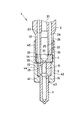
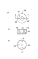
図1および図2は本発明の実施形態を示したもので、図1は内燃機関用燃料噴射ノズルの主要構造を示した図で、図2は内燃機関用燃料噴射ノズルのチップパッキンを示した図である。
【0011】
本実施形態の内燃機関用燃料噴射ノズル1は、流体移送装置としての蓄圧式燃料噴射装置(コモンレールシステム)に使用されるインジェクタの燃料噴射ノズルで、図示しないディーゼルエンジンの各気筒毎に取り付けられ、図示しない高圧供給ポンプ(サプライポンプ)から圧送された高圧燃料をコモンレールの蓄圧室内に蓄圧し、この蓄圧室内に蓄圧した高圧燃料を直接燃焼室内に霧状に噴射する直接噴射タイプの内燃機関用燃料噴射弁である。
【0012】
この内燃機関用燃料噴射ノズル1は、図示しないノズルニードルを収容するノズルボデー2、ノズルニードルを閉弁側に付勢するスプリング等の付勢手段を収容するノズルホルダー3、ノズルボデー2とノズルホルダー3との間に配置されたチップパッキン4、およびこのチップパッキン4を介してノズルボデー2とノズルホルダー3とを所定の締結軸力により固定するリテーニングナット5等から構成されている。
【0013】
ノズルボデー2は、本発明の第1管状部品に相当するもので、先端側(図示下側)に、高圧燃料を噴射するための燃料噴射孔(図示せず)を1個または複数個備えた第1筒状体である。このノズルボデー2の内部には、棒状のノズルニードルを摺動自在に保持するための摺動孔11が形成されている。この摺動孔11の中間部位には、孔径が拡げられた油溜り16が設けられている。また、ノズルボデー2の図示上端面(チップパッキン4との密着面)には、チップパッキン4の第1ピン孔12(後述する)と連通し、ノズルボデー2とチップパッキン4の組み付けの際の位置決めおよび回転を防止する第1ノックピン(図示せず)が嵌まり込む第1ピン孔(図示せず)が形成されている。
【0014】
さらに、ノズルボデー2には、このノズルボデー2の図示上端側の密着面から油溜り16へ延びる燃料送出路(本発明の第1流体通路に相当する)15が設けられている。なお、この燃料送出路15は、ノズルホルダー3の燃料供給路13(後述する)と連通し、且つチップパッキン4の燃料中継路14(後述する)と連通することで、コモンレールの蓄圧室から油溜り16へ高圧燃料を送り込むための燃料通路を構成する。
【0015】
ノズルホルダー3は、本発明の第2管状部品に相当するもので、内部にスプリング等の付勢手段(図示せず)およびノズルニードルに連結するプレッシャピンまたは油圧ピストン(図示せず)を収容するスプリング室21が設けられた第2筒状体である。このスプリング室21は、中間の段差23より図示下側の内径寸法が、図示上側の内径寸法よりも大きく設けられている。
【0016】
なお、油圧ピストンの他端には、図示しない電磁弁等の電磁式アクチュエータにより油圧が給排される油圧制御室(図示せず)が設けられている。この油圧制御室から油圧が抜かれると、ノズルニードルおよび油圧ピストンがスプリング等の付勢手段の付勢力に抗して軸方向に移動(リフト)する。つまりノズルニードルが開弁する。また、油圧制御室内に油圧が導入されると、ノズルニードルおよび油圧ピストンがスプリング等の付勢手段の付勢力によって軸方向に移動して、ノズルニードルが閉弁する。
【0017】
また、ノズルホルダー3の図示下端面(チップパッキン4との密着面)には、チップパッキン4の第2ピン孔22(後述する)と連通し、ノズルホルダー3とチップパッキン4の組み付けの際の位置決めおよび回転を防止する第2ノックピン(図示せず)が嵌まり込む第2ピン孔(図示せず)が形成されている。そして、ノズルホルダー3には、コモンレールの分岐管に接続される高圧配管との継手部(図示せず)が設けられており、ここでコモンレールから供給された高圧燃料を受ける。
【0018】
ノズルホルダー3の継手部の内部、およびスプリング室21の周囲には、供給された高圧燃料を、チップパッキン4の燃料中継路14、ノズルボデー2の燃料送出路15を介してノズルボデー2の油溜り16へ送るための燃料供給路(本発明の第2流体通路に相当する)13が設けられている。さらに、ノズルホルダー3には、スプリング室21に導かれた燃料を、燃料タンク等の低圧配管系内へ戻すための燃料逃がし通路(リーク回収用通路)24が設けられている。そして、ノズルホルダー3の図示下端側の外周には、リテーニングナット5の雌ねじ部25(後述する)と締結される雄ねじ部26が設けられている。
【0019】
チップパッキン4は、本発明の筒状部品に相当するもので、ノズルボデー2の図示上端側の密着面とノズルホルダー3の図示下端側の密着面との間に配置された環状体であるために、ノズルボデー2の燃料送出路15とノズルホルダー3の燃料供給路13とを連通するための燃料中継路(本発明の連通路に相当する)14が設けられている。このチップパッキン4の内部には、径大孔31が形成されており、この径大孔31の内径寸法は、その図示下方の径小孔32の内径寸法よりも大径に設けられている。
【0020】
なお、チップパッキン4の中央部の図示下端面は、ノズルニードルの開弁時にノズルニードルの移動量(リフト量)が最大リフト量に達した際にノズルニードルの移動を規制する規制面とされている。また、チップパッキン4の径大孔31および径小孔32の周囲には、ノズルボデー2の第1ピン孔と連通し、ノズルボデー2とチップパッキン4の組み付けの際の位置決めおよび回転を防止する第1ノックピンが嵌まり込む第1ピン孔12、およびノズルホルダー3の第2ピン孔と連通し、ノズルホルダー3とチップパッキン4の組み付けの際の位置決めおよび回転を防止する第2ノックピンが嵌まり込む第2ピン孔22が形成されている。
【0021】
そして、チップパッキン4の図示下端面(ノズルボデー2との密着面)には、その図示下端面のシール面積の低減による流体通路周りのシール面圧を向上させるための凹状の肉盗み部(図2の斜線部)35が複数個設けられている。なお、チップパッキン4の凹状の肉盗み部35を除く図示下端側の密着面は、ノズルボデー2の図示上端側の密着面(シール面)に緊密的に密着して、燃料送出路15と燃料中継路14との高圧シール性を確保するためのシール面38となる。
【0022】
また、チップパッキン4の図示上端面(ノズルホルダー3との密着面)には、その図示上端面のシール面積の低減による流体通路周りのシール面圧を向上させるための凹状の肉盗み部(図2の斜線部)36が複数個設けられている。そして、チップパッキン4の図示上端面の肉盗み部36と径小孔32との間を連通する凹状の肉盗み部(図2の格子状斜線部)37は、スプリング室21、径大孔31および径小孔32に導かれた燃料を、燃料タンク等の低圧配管系内へ戻すためのリーク回収用通路と兼用されている。なお、チップパッキン4の凹状の肉盗み部36、37を除く図示上端側の密着面は、ノズルホルダー3の図示下端側の密着面(シール面)に緊密的に密着して、燃料供給路13と燃料中継路14との高圧シール性を確保するためのシール面39となる。
【0023】
リテーニングナット5は、本発明の筒状の締結部材に相当するもので、チップパッキン4を介してノズルボデー2の図示上端側の密着面とノズルホルダー3の図示下端側の密着面とを所定の締結軸力で密着させるものである。このリテーニングナット5は、ノズルボデー2の図示下端面に設けられた肩部41を受けるための奥座面42を有する円環状の受け部43、およびこの受け部43の外周端より図示上方へ延びる円管状のスリーブ部44が設けられている。そのスリーブ部44の内径寸法は、その図示上方の肉薄部45の内径寸法よりも大径に設けられている。なお、肉薄部45の内周には、ノズルホルダー3の図示下端側の雄ねじ部26と締結される雌ねじ部25が設けられている。
【0024】
[実施形態の作用]
次に、本実施形態の内燃機関用燃料噴射ノズル1の作用を図1および図2に基づいて簡単に説明する。
【0025】
高圧源であるコモンレールから高圧配管、燃料供給路13、燃料中継路14、燃料送出路15を介して油溜り16に高圧燃料が供給されている。そして、油圧ピストンの他端に設けられた油圧制御室より燃料が抜かれると、油溜り16内の油圧力がスプリング等の付勢手段の付勢力よりも大きくなり、油圧ピストンおよびノズルニードルが燃料噴射孔を開く方向へ移動する。これにより、ノズルボデー2の弁座からノズルニードルが離脱することで、油溜り16内の高圧燃料がノズルボデー2の先端部に設けられた1個または複数個の燃料噴射孔よりディーゼルエンジンの燃焼室内へ噴射される。
【0026】
なお、燃料供給路13、燃料中継路14、燃料送出路15および油溜り16からノズルホルダー3のスプリング室21およびチップパッキン4の径大孔31および径小孔32とノズルニードルとの間に漏出(リーク)した燃料は、ノズルホルダー3の図示下端側の密着面とチップパッキン4の図示上端側の密着面の凹状の肉盗み部37との間に形成されるリーク回収用通路、ノズルホルダー3内部の燃料逃がし通路(リーク回収用通路)24を通って燃料タンク等の低圧配管系内へ戻される。
【0027】
[実施形態の効果]
以上のように、本実施形態の内燃機関用燃料噴射ノズル1においては、ノズルボデー2の図示上端側の密着面(シール面)とノズルホルダー3の図示下端側の密着面(シール面)との間に配置されるチップパッキン4の図示下端側の密着面および図示上端側の密着面より凹状の肉盗み部35、36を堀り下げている。この凹状の肉盗み部35、36は、燃料中継路14と干渉せず、燃料中継路14から高圧燃料が抜けることなく、近年の燃料噴射圧力の高圧化に対応可能な高圧シール性を確保できるように加工されている。
【0028】
また、ノズルホルダー3の図示下端側の密着面(シール面)と密着する密着面上に凹状の肉盗み部36と同様に掘り下げられた凹状の肉盗み部37が設けられており、その凹状の肉盗み部37がノズルホルダー3の燃料逃がし通路(リーク回収用通路)24と繋がるように加工されている。これらの加工をチップパッキン4の図示上下端面に施すことにより、材料の変形や強度面からの制約を受ける締結軸力を大きくすることなく、シール面積を低減することができる。 なお、上記肉盗み部35〜37は、切削加工にて形成されている。
【0029】
したがって、シール面積の低減による少ない締結軸力での流体通路周りのシール面圧の向上を図ることができるため、近年の燃料噴射圧力の高圧化に対する流体通路周りのシール面圧の向上が可能となり、且つ従来のリーク回収用通路110分の大きさの凹みを設けることなく、凹状の肉盗み部36とこれに連通する凹状の肉盗み部37をリーク回収用通路として兼用することができるので、ノズルホルダー3の密着面の形状が簡素な形状となり、コストダウンを図れる。
【0030】
ここで、本実施形態では、燃料噴射圧力の高圧化が進むディーゼルエンジンの内燃機関用燃料噴射ノズル1において、チップパッキン4を介してノズルボデー2の図示上端側の密着面とノズルホルダー3の図示下端側の密着面とを所定の締結軸力で密着させるリテーニングナット5の締結軸力を向上させることなく、各シール面の高圧シール性を確保することができる。
【0031】
これにより、チップパッキン4を介してノズルボデー2の密着面とノズルホルダー3の密着面とを締結するリテーニングナット5の締結時において、締結軸力によってノズルボデー2の肩部41とリテーニングナット5の奥座面42との間に生ずる摩擦力によりノズルボデー2がひねられることはなく、ノズルニードルの摺動部の円筒度の悪化を防ぐことができ、ノズルニードルの摺動不良は起きない。また、波及効果として、本構成にあるような蓄圧式燃料噴射装置のみならず、高圧シール面を有する全てのものに関して適用が可能である。
【0032】
[他の実施形態]
本実施形態では、本発明を、高圧供給ポンプおよびコモンレールを備えた蓄圧式燃料噴射装置(コモンレールシステム)に使用されるインジェクタとしての内燃機関用燃料噴射ノズル1のシール面圧向上構造の例を示したが、本発明を、列型燃料噴射ポンプや分配型燃料噴射ポンプからインジェクタへ直接高圧燃料が噴射されて、油溜り内の燃料圧力がスプリング等の付勢手段の付勢力よりも大きくなるとノズルニードルが弁座よりリフトするような燃料噴射装置に使用されるインジェクタの内燃機関用燃料噴射ノズルのシール面圧向上構造に適用しても良い。また、本発明を、燃料噴射孔の噴孔面積を変更可能な可変噴孔ノズルに適用しても良い。
【図面の簡単な説明】
【図1】内燃機関用燃料噴射ノズルの主要構成を示した断面図である(実施形態)。
【図2】(a)は内燃機関用燃料噴射ノズルのチップパッキンの上端面を示した平面図で、(b)は(a)のA−A断面図で、(c)はチップパッキンの下端面を示した平面図である(実施形態)。
【図3】内燃機関用燃料噴射ノズルの主要構成を示した断面図である(従来の技術)。
【図4】(a)は内燃機関用燃料噴射ノズルのチップパッキンの上端面を示した平面図で、(b)は(a)のB−B断面図で、(c)はチップパッキンの下端面を示した平面図である(従来の技術)。
【符号の説明】
1 内燃機関用燃料噴射ノズル
2 ノズルボデー(第1管状部品)
3 ノズルホルダー(第2管状部品)
4 チップパッキン(筒状部品)
5 リテーニングナット(筒状の締結部材)
13 燃料供給路(第2流体通路、燃料通路)
14 燃料中継路(連通路、燃料通路)
15 燃料送出路(第1流体通路、燃料通路)
16 油溜り
35〜37 凹状の肉盗み部
38、39 シール面[0001]
BACKGROUND OF THE INVENTION
The present invention provides a seal surface pressure around a fluid passage with a small fastening axial force by reducing a seal area between the contact surfaces of the first tubular part and the tubular part or between the contact surfaces of the second tubular part and the tubular part. In particular, the present invention relates to a structure for improving the seal surface pressure of a fuel injection nozzle for an internal combustion engine attached to the internal combustion engine.
[0002]
[Prior art]
Conventionally, there is a
[0003]
The
[0004]
Further, inside the
[0005]
[Problems to be solved by the invention]
However, in recent years, in fuel injection nozzles for diesel engines, where fuel injection pressures have been increasing, in order to ensure higher high-pressure sealability, the tightening axial force of the retaining nut is increased and the contact surface between the parts is increased. Improvement of the seal surface pressure is required. However, when the retaining nut that fastens the contact surface of the nozzle body and the contact surface of the nozzle holder via the tip packing is fastened, the friction generated between the shoulder of the nozzle body and the back surface of the retaining nut is caused by the fastening axial force. The nozzle body is twisted by the force, the cylindricality of the sliding portion of the nozzle needle is deteriorated, and there is a concern that the nozzle needle may slide poorly.
[0006]
Therefore, there are many restrictions in terms of deformation and strength of each part such as the nozzle body, and it is costly to adopt a structure that improves the sealing surface pressure of the close contact surfaces of each part by increasing the fastening axial force of the retaining nut. Is also very difficult. Therefore, it is desirable to improve the seal surface pressure around the fuel passage with a small fastening axial force by reducing the seal area. However, as each component is reduced in size, the contact surface between the components is only for the purpose of reducing the seal area. There was a problem that it was disadvantageous to provide a recess in the surface.
[0007]
OBJECT OF THE INVENTION
The present invention provides a seal surface pressure around a fluid passage with a small fastening axial force by reducing a seal area between the contact surfaces of the first tubular part and the tubular part or between the contact surfaces of the second tubular part and the tubular part. In addition, the concave meat stealing portion provided on the contact surface between the first tubular part and the cylindrical part or the contact surface between the second tubular part and the tubular part can also be used as a leak recovery passage. It is an object of the present invention to provide a structure for improving the seal surface pressure of a fluid transfer device that can be used.
[0008]
[Means for Solving the Problems]
According to the invention described in claim 1, the contact surface between the first tubular portion goods and the tubular portion products, some have the concave thinned-out part in the contact surface between the second tubular part products and the cylindrical portion GOODS by providing the adhesion surfaces of the first tubular portion goods and the tubular portion products, there have is in a small tightening axial force by reducing the sealing surface area of the contact surfaces of the second tubular portion article and the cylindrical portion gOODS The seal surface pressure around the fluid passage can be improved. Further, since the concave meat stealing portion provided on the contact surface between the first tubular part and the tubular part or the contact surface between the second tubular part and the tubular part can be used as the leak collecting passage, the first tubular part is provided. Alternatively, the shape of the contact surface of the second tubular part on the cylindrical part side becomes a simple shape, and the cost can be reduced.
Further, according to the invention described in
[0009]
According to the second aspect of the present invention, the cylindrical part is formed with a small-diameter hole and a large-diameter hole having a larger diameter than the small-diameter hole. Communicate. According to the invention described in
[0010]
DETAILED DESCRIPTION OF THE INVENTION
[Configuration of the embodiment]
1 and 2 show an embodiment of the present invention. FIG. 1 shows the main structure of a fuel injection nozzle for an internal combustion engine, and FIG. 2 shows a tip packing of the fuel injection nozzle for the internal combustion engine. FIG.
[0011]
The fuel injection nozzle 1 for an internal combustion engine of the present embodiment is a fuel injection nozzle of an injector used for a pressure accumulation type fuel injection device (common rail system) as a fluid transfer device, and is attached to each cylinder of a diesel engine (not shown). Direct injection type internal combustion engine fuel that accumulates high-pressure fuel pumped from a high-pressure supply pump (supply pump) (not shown) in a common rail accumulator, and injects the accumulated high-pressure fuel directly into the combustion chamber in the form of a mist It is an injection valve.
[0012]
The fuel injection nozzle 1 for an internal combustion engine includes a
[0013]
The
[0014]
Further, the
[0015]
The
[0016]
The other end of the hydraulic piston is provided with a hydraulic control chamber (not shown) in which hydraulic pressure is supplied and discharged by an electromagnetic actuator such as an electromagnetic valve (not shown). When the hydraulic pressure is released from the hydraulic control chamber, the nozzle needle and the hydraulic piston move (lift) in the axial direction against the biasing force of biasing means such as a spring. That is, the nozzle needle is opened. When oil pressure is introduced into the oil pressure control chamber, the nozzle needle and the hydraulic piston move in the axial direction by the urging force of the urging means such as a spring, and the nozzle needle is closed.
[0017]
In addition, the lower end surface of the
[0018]
In the joint portion of the
[0019]
The tip packing 4 corresponds to the cylindrical part of the present invention and is an annular body disposed between the close contact surface on the upper end side of the
[0020]
The lower end surface of the center portion of the tip packing 4 is a restriction surface that restricts the movement of the nozzle needle when the movement amount (lift amount) of the nozzle needle reaches the maximum lift amount when the nozzle needle is opened. Yes. Further, around the large-
[0021]
A concave meat stealing portion (FIG. 2) for improving the sealing surface pressure around the fluid passage by reducing the sealing area of the lower end surface shown in the figure on the lower end surface (contact surface with the nozzle body 2) of the
[0022]
In addition, a concave meat stealing portion for improving the seal surface pressure around the fluid passage by reducing the sealing area of the upper end surface of the illustrated tip packing 4 (the contact surface with the nozzle holder 3) (see FIG. (2 hatched portions) 36 are provided. A concave meat stealing portion (lattice hatched portion in FIG. 2) 37 communicating between the
[0023]
The retaining
[0024]
[Operation of the embodiment]
Next, the operation of the internal combustion engine fuel injection nozzle 1 of the present embodiment will be briefly described with reference to FIGS. 1 and 2.
[0025]
High pressure fuel is supplied to the
[0026]
In addition, leakage from the
[0027]
[Effect of the embodiment]
As described above, in the fuel injection nozzle 1 for the internal combustion engine of the present embodiment, the space between the close contact surface (seal surface) of the
[0028]
Further, a concave
[0029]
Accordingly, since the seal surface pressure around the fluid passage can be improved with a small fastening axial force by reducing the seal area, it becomes possible to improve the seal surface pressure around the fluid passage against the recent increase in fuel injection pressure. In addition, the concave
[0030]
Here, in this embodiment, in the fuel injection nozzle 1 for an internal combustion engine of a diesel engine whose fuel injection pressure is increasing, the close contact surface on the upper end side of the
[0031]
As a result, when the retaining
[0032]
[Other Embodiments]
In this embodiment, the present invention shows an example of a structure for improving the seal surface pressure of a fuel injection nozzle 1 for an internal combustion engine as an injector used in a pressure accumulation fuel injection device (common rail system) having a high-pressure supply pump and a common rail. However, when the high pressure fuel is directly injected from the row type fuel injection pump or the distribution type fuel injection pump into the injector, the fuel pressure in the oil sump becomes larger than the urging force of the urging means such as a spring. The present invention may be applied to a structure for improving the seal surface pressure of a fuel injection nozzle for an internal combustion engine of an injector used in a fuel injection device in which a needle is lifted from a valve seat. Further, the present invention may be applied to a variable nozzle nozzle that can change the nozzle hole area of the fuel injection hole.
[Brief description of the drawings]
FIG. 1 is a cross-sectional view showing a main configuration of a fuel injection nozzle for an internal combustion engine (embodiment).
2A is a plan view showing an upper end surface of a tip packing of a fuel injection nozzle for an internal combustion engine, FIG. 2B is a sectional view taken along line AA of FIG. 2A, and FIG. It is the top view which showed the end surface (embodiment).
FIG. 3 is a cross-sectional view showing the main configuration of a fuel injection nozzle for an internal combustion engine (prior art).
4A is a plan view showing an upper end surface of a tip packing of a fuel injection nozzle for an internal combustion engine, FIG. 4B is a sectional view taken along line BB in FIG. 4A, and FIG. It is the top view which showed the end surface (prior art).
[Explanation of symbols]
1 Fuel injection nozzle for
3 Nozzle holder (second tubular part)
4 Chip packing (tubular parts)
5 Retaining nut (tubular fastening member)
13 Fuel supply passage (second fluid passage, fuel passage)
14 Fuel junction (communication passage, fuel passage)
15 Fuel delivery path (first fluid passage, fuel passage)
16 Oil reservoir 35-37 Concave
Claims (5)
前記第1管状部品と前記筒状部品との密着面、あるいは前記第2管状部品と前記筒状部品との密着面には、シール面積の低減による流体通路周りのシール面圧を向上させるための凹状の肉盗み部が設けられており、
前記凹状の肉盗み部を、流体を回収するためのリーク回収用通路として兼用することを特徴とする流体移送装置のシール面圧向上構造。A first tubular part having a first fluid passage therein; a second tubular part having a second fluid passage therein; and being sandwiched between the first tubular part and the second tubular part, And a cylindrical part having a communication path for communicating the second fluid passages,
The contact surface between the first tubular part and the tubular part or the contact surface between the second tubular part and the tubular part is for improving the seal surface pressure around the fluid passage by reducing the seal area. There is a concave meat stealing section ,
A structure for improving the seal surface pressure of a fluid transfer device, wherein the concave meat stealing portion is also used as a leak recovery passage for recovering a fluid.
前記筒状部品には、径小孔およびこの径小孔よりも大径の径大孔が形成されており、
前記凹状の肉盗み部は、前記径大孔と連通していることを特徴とする流体移送装置のシール面圧向上構造。In the structure for improving the seal surface pressure of the fluid transfer device according to claim 1,
The cylindrical part is formed with a small diameter hole and a large diameter hole larger than the small diameter hole,
The structure for improving the seal surface pressure of a fluid transfer device, wherein the concave meat stealing portion communicates with the large-diameter hole .
前記ノズルボデーと前記チップパッキンとの密着面、あるいは前記ノズルホルダーと前記チップパッキンとの密着面には、シール面積の低減による流体通路周りのシール面圧を向上させるための凹状の肉盗み部が設けられており、
前記凹状の肉盗み部を、流体を回収するためのリーク回収用通路として兼用することを特徴とする燃料噴射ノズルのシール面圧向上構造。A nozzle body for slidably supporting the nozzle needle therein, and a second fuel passage therein for energizing the nozzle needle toward the valve closing side. A nozzle holder that accommodates the biasing means, and a communication passage that is sandwiched between the nozzle body and the nozzle holder and communicates the first and second fuel passages. With chip packing to regulate the lift amount,
The contact surface between the nozzle body and the chip packing or the contact surface between the nozzle holder and the chip packing is provided with a concave meat stealing portion for improving the seal surface pressure around the fluid passage by reducing the seal area. It is and,
A structure for improving the seal surface pressure of a fuel injection nozzle, wherein the concave meat stealing portion is also used as a leak recovery passage for recovering a fluid .
前記チップパッキンには、径小孔およびこの径小孔よりも大径の径大孔が形成されており、
前記凹状の肉盗み部は、前記径大孔と連通していることを特徴とする燃料噴射ノズルのシール面圧向上構造。In the structure for improving the seal surface pressure of the fuel injection nozzle according to claim 3,
In the chip packing, a small diameter hole and a large diameter hole larger than the small diameter hole are formed,
The structure for improving the seal surface pressure of a fuel injection nozzle, wherein the concave meat stealing portion communicates with the large-diameter hole .
前記チップパッキンを介して前記ノズルボデーの密着面と前記ノズルホルダーの密着面を所定の締結軸力で密着させる筒状の締結部材を備えたことを特徴とする燃料噴射ノズルのシール面圧向上構造。In the structure for improving the seal surface pressure of the fuel injection nozzle according to claim 3 ,
A structure for improving a sealing surface pressure of a fuel injection nozzle, comprising: a cylindrical fastening member that attaches the contact surface of the nozzle body and the contact surface of the nozzle holder with a predetermined fastening axial force via the chip packing.
Priority Applications (4)
| Application Number | Priority Date | Filing Date | Title |
|---|---|---|---|
| JP2001036474A JP3928362B2 (en) | 2001-02-14 | 2001-02-14 | Structure to improve seal surface pressure of fluid transfer device |
| EP02003318A EP1236886B1 (en) | 2001-02-14 | 2002-02-13 | Arrangement for increasing the sealing surface pressure of fluid conducting system |
| DE60208829T DE60208829T2 (en) | 2001-02-14 | 2002-02-13 | Device for surface pressure increase in fluid-carrying pipelines |
| US10/074,216 US6666390B2 (en) | 2001-02-14 | 2002-02-14 | Sealing surface pressure increasing arrangement of fluid conducting system |
Applications Claiming Priority (1)
| Application Number | Priority Date | Filing Date | Title |
|---|---|---|---|
| JP2001036474A JP3928362B2 (en) | 2001-02-14 | 2001-02-14 | Structure to improve seal surface pressure of fluid transfer device |
Publications (2)
| Publication Number | Publication Date |
|---|---|
| JP2002243040A JP2002243040A (en) | 2002-08-28 |
| JP3928362B2 true JP3928362B2 (en) | 2007-06-13 |
Family
ID=18899742
Family Applications (1)
| Application Number | Title | Priority Date | Filing Date |
|---|---|---|---|
| JP2001036474A Expired - Lifetime JP3928362B2 (en) | 2001-02-14 | 2001-02-14 | Structure to improve seal surface pressure of fluid transfer device |
Country Status (4)
| Country | Link |
|---|---|
| US (1) | US6666390B2 (en) |
| EP (1) | EP1236886B1 (en) |
| JP (1) | JP3928362B2 (en) |
| DE (1) | DE60208829T2 (en) |
Families Citing this family (20)
| Publication number | Priority date | Publication date | Assignee | Title |
|---|---|---|---|---|
| DE10213380B4 (en) * | 2001-09-04 | 2010-08-12 | Robert Bosch Gmbh | Fuel injection valve for an internal combustion engine |
| EP1293664A3 (en) * | 2001-09-18 | 2004-03-10 | Siemens Aktiengesellschaft | Fuel injection valve for an internal combustion engine |
| EP1744053B1 (en) * | 2001-11-02 | 2008-09-17 | Bosch Automotive Systems Corporation | Fuel path sealing structure |
| EP1518050B1 (en) * | 2002-07-02 | 2011-10-05 | Continental Automotive GmbH | Injector for an injection system |
| US6880766B2 (en) * | 2003-02-28 | 2005-04-19 | Caterpillar Inc | Leak arrest volume for reducing component separation and fuel injector using same |
| JP2006183471A (en) * | 2004-12-24 | 2006-07-13 | Denso Corp | Injector |
| JP2006181577A (en) * | 2004-12-24 | 2006-07-13 | Denso Corp | High pressure piping parts manufacturing method and high pressure piping parts |
| DE102005004069A1 (en) * | 2005-01-28 | 2006-08-03 | Volkswagen Mechatronic Gmbh & Co. Kg | Injection device e.g. pump-nozzle-injection device, for e.g. diesel engine, has sealing arrangement with O-rings to effect sealing of interface, which includes sealing surface with grooves to accommodate O-rings, at cavity or channel |
| JP2007040243A (en) * | 2005-08-04 | 2007-02-15 | Denso Corp | High pressure fuel seal structure of fuel injection device |
| JP4605092B2 (en) * | 2006-05-18 | 2011-01-05 | 株式会社デンソー | Fuel supply pump |
| DE102006049202A1 (en) * | 2006-10-18 | 2008-04-30 | Man Diesel Se | Sealing system for fuel injection device of common rail diesel internal-combustion engine, has casing protruding from recess in partly assembled condition, rests on surface of components, and deformed such that surfaces contact each other |
| JP4730373B2 (en) | 2007-11-21 | 2011-07-20 | 株式会社デンソー | Fuel injection valve |
| EP2478210A4 (en) * | 2009-09-17 | 2013-06-05 | Int Engine Intellectual Prop | High-pressure unit fuel injector |
| US20120103308A1 (en) * | 2010-10-28 | 2012-05-03 | Caterpillar, Inc. | Two-Way Valve Orifice Plate for a Fuel Injector |
| US8448878B2 (en) * | 2010-11-08 | 2013-05-28 | Caterpillar Inc. | Fuel injector with needle control system that includes F, A, Z and E orifices |
| DE102011076957A1 (en) * | 2011-06-06 | 2012-12-06 | Robert Bosch Gmbh | Fuel injection valve for internal combustion engines |
| DE102012208075A1 (en) * | 2012-05-15 | 2013-11-21 | Man Diesel & Turbo Se | Injector for a fuel supply system of an internal combustion engine and fuel supply system |
| GB2549094A (en) * | 2016-04-04 | 2017-10-11 | Delphi Int Operations Luxembourg Sarl | Fuel injector |
| US11248575B1 (en) | 2020-09-18 | 2022-02-15 | Caterpillar Inc. | Fuel injector with internal leak passage to injector drain |
| US11174827B1 (en) | 2020-09-18 | 2021-11-16 | Caterpillar Inc. | Fuel injector with internal radial seal with thin wall counterbore |
Family Cites Families (9)
| Publication number | Priority date | Publication date | Assignee | Title |
|---|---|---|---|---|
| US3406912A (en) * | 1966-05-09 | 1968-10-22 | Bosch Arma Corp | Capsulated fuel injection nozzle |
| US5472142A (en) | 1992-08-11 | 1995-12-05 | Nippondenso Co., Ltd. | Accumulator fuel injection apparatus |
| US5553781A (en) * | 1995-01-03 | 1996-09-10 | Servojet Products International | Conversion of jerk type injector to accumulator type injector |
| DE19523243B4 (en) * | 1995-06-27 | 2009-04-02 | Robert Bosch Gmbh | Fuel injection valve for internal combustion engines with a clamping nut with a conically formed annular shoulder |
| DE19752496A1 (en) * | 1997-11-27 | 1999-06-02 | Bosch Gmbh Robert | Fuel injection valve for internal combustion engines |
| GB9810208D0 (en) * | 1998-05-13 | 1998-07-08 | Lucas Ind Plc | Fuel injector |
| DE19914720B4 (en) * | 1999-03-31 | 2005-10-13 | Siemens Ag | Fuel injection valve for an internal combustion engine |
| DE10102233A1 (en) * | 2001-01-19 | 2002-07-25 | Bosch Gmbh Robert | High-pressure fuel system for internal combustion engines |
| DE10105368A1 (en) * | 2001-02-06 | 2002-08-29 | Siemens Ag | Fuel injection nozzle for an internal combustion engine |
-
2001
- 2001-02-14 JP JP2001036474A patent/JP3928362B2/en not_active Expired - Lifetime
-
2002
- 2002-02-13 DE DE60208829T patent/DE60208829T2/en not_active Expired - Lifetime
- 2002-02-13 EP EP02003318A patent/EP1236886B1/en not_active Expired - Lifetime
- 2002-02-14 US US10/074,216 patent/US6666390B2/en not_active Expired - Lifetime
Also Published As
| Publication number | Publication date |
|---|---|
| JP2002243040A (en) | 2002-08-28 |
| US6666390B2 (en) | 2003-12-23 |
| DE60208829T2 (en) | 2006-08-31 |
| EP1236886B1 (en) | 2006-01-25 |
| DE60208829D1 (en) | 2006-04-13 |
| EP1236886A3 (en) | 2004-01-02 |
| US20020109022A1 (en) | 2002-08-15 |
| EP1236886A2 (en) | 2002-09-04 |
Similar Documents
| Publication | Publication Date | Title |
|---|---|---|
| JP3928362B2 (en) | Structure to improve seal surface pressure of fluid transfer device | |
| CN105257447B (en) | High-pressure fuel feed pump | |
| US6145492A (en) | Control valve for a fuel injection valve | |
| JP4898840B2 (en) | Fuel injection device for internal combustion engine | |
| US20090229576A1 (en) | Coupling device | |
| US7866575B2 (en) | Pressure actuated fuel injector | |
| US6609667B2 (en) | Fuel injection nozzle | |
| US7886718B2 (en) | Fuel injector having integral body guide and nozzle case for pressure containment | |
| US20030075154A1 (en) | Fuel-injection system for internal combustion engines | |
| US7954475B2 (en) | Fuel injector | |
| JP3366495B2 (en) | Fluid ejection device | |
| US6138643A (en) | Fuel injection device with oil seal | |
| US5427073A (en) | Fuel pump | |
| US11280306B1 (en) | Fuel injector having dry-running protection valve and fuel system using same | |
| GB2428742A (en) | Fuel injector with a high pressure fuel seal structure | |
| US20040011891A1 (en) | Fuel injector having two-way valve control | |
| US20020170536A1 (en) | Fuel injection device for combustion engines | |
| JP3931718B2 (en) | Fuel injection device | |
| US11002233B1 (en) | Single-fluid common rail fuel injector with fuel recovery fitting and engine system using same | |
| EP1167751A1 (en) | Fuel injector | |
| JP2003139015A5 (en) | ||
| JP2008163772A (en) | Fuel control valve | |
| JP2009250115A (en) | Joint device for delivery pipe | |
| JPH07259652A (en) | Fuel and water injection device of water injection type diesel engine | |
| JP2020002784A (en) | Fuel injection device and fuel injection valve |
Legal Events
| Date | Code | Title | Description |
|---|---|---|---|
| A131 | Notification of reasons for refusal |
Free format text: JAPANESE INTERMEDIATE CODE: A131 Effective date: 20060404 |
|
| A521 | Request for written amendment filed |
Free format text: JAPANESE INTERMEDIATE CODE: A523 Effective date: 20060529 |
|
| TRDD | Decision of grant or rejection written | ||
| A01 | Written decision to grant a patent or to grant a registration (utility model) |
Free format text: JAPANESE INTERMEDIATE CODE: A01 Effective date: 20070213 |
|
| A61 | First payment of annual fees (during grant procedure) |
Free format text: JAPANESE INTERMEDIATE CODE: A61 Effective date: 20070226 |
|
| R150 | Certificate of patent or registration of utility model |
Free format text: JAPANESE INTERMEDIATE CODE: R150 Ref document number: 3928362 Country of ref document: JP Free format text: JAPANESE INTERMEDIATE CODE: R150 |
|
| FPAY | Renewal fee payment (event date is renewal date of database) |
Free format text: PAYMENT UNTIL: 20100316 Year of fee payment: 3 |
|
| FPAY | Renewal fee payment (event date is renewal date of database) |
Free format text: PAYMENT UNTIL: 20110316 Year of fee payment: 4 |
|
| FPAY | Renewal fee payment (event date is renewal date of database) |
Free format text: PAYMENT UNTIL: 20120316 Year of fee payment: 5 |
|
| FPAY | Renewal fee payment (event date is renewal date of database) |
Free format text: PAYMENT UNTIL: 20120316 Year of fee payment: 5 |
|
| FPAY | Renewal fee payment (event date is renewal date of database) |
Free format text: PAYMENT UNTIL: 20130316 Year of fee payment: 6 |
|
| FPAY | Renewal fee payment (event date is renewal date of database) |
Free format text: PAYMENT UNTIL: 20140316 Year of fee payment: 7 |
|
| R250 | Receipt of annual fees |
Free format text: JAPANESE INTERMEDIATE CODE: R250 |
|
| R250 | Receipt of annual fees |
Free format text: JAPANESE INTERMEDIATE CODE: R250 |
|
| R250 | Receipt of annual fees |
Free format text: JAPANESE INTERMEDIATE CODE: R250 |
|
| R250 | Receipt of annual fees |
Free format text: JAPANESE INTERMEDIATE CODE: R250 |
|
| R250 | Receipt of annual fees |
Free format text: JAPANESE INTERMEDIATE CODE: R250 |
|
| R250 | Receipt of annual fees |
Free format text: JAPANESE INTERMEDIATE CODE: R250 |
|
| R250 | Receipt of annual fees |
Free format text: JAPANESE INTERMEDIATE CODE: R250 |
|
| EXPY | Cancellation because of completion of term |