EP1674126A1 - Intra-aortic balloon catheter - Google Patents
Intra-aortic balloon catheter Download PDFInfo
- Publication number
- EP1674126A1 EP1674126A1 EP04771052A EP04771052A EP1674126A1 EP 1674126 A1 EP1674126 A1 EP 1674126A1 EP 04771052 A EP04771052 A EP 04771052A EP 04771052 A EP04771052 A EP 04771052A EP 1674126 A1 EP1674126 A1 EP 1674126A1
- Authority
- EP
- European Patent Office
- Prior art keywords
- tube
- balloon
- distal end
- end portion
- inner tube
- Prior art date
- Legal status (The legal status is an assumption and is not a legal conclusion. Google has not performed a legal analysis and makes no representation as to the accuracy of the status listed.)
- Withdrawn
Links
- 210000004369 blood Anatomy 0.000 claims abstract description 68
- 239000008280 blood Substances 0.000 claims abstract description 68
- 230000008602 contraction Effects 0.000 claims abstract description 46
- 239000012530 fluid Substances 0.000 claims abstract description 41
- 230000017531 blood circulation Effects 0.000 claims abstract description 36
- 238000009530 blood pressure measurement Methods 0.000 claims abstract description 19
- 210000000709 aorta Anatomy 0.000 claims description 14
- 210000001367 artery Anatomy 0.000 claims description 12
- 210000004204 blood vessel Anatomy 0.000 claims description 2
- 230000036772 blood pressure Effects 0.000 description 51
- 238000010009 beating Methods 0.000 description 21
- 239000000463 material Substances 0.000 description 19
- 210000002376 aorta thoracic Anatomy 0.000 description 17
- 210000002302 brachial artery Anatomy 0.000 description 17
- 241000283707 Capra Species 0.000 description 12
- 238000000605 extraction Methods 0.000 description 12
- 238000000034 method Methods 0.000 description 12
- 229920001971 elastomer Polymers 0.000 description 9
- 239000000806 elastomer Substances 0.000 description 9
- 238000005304 joining Methods 0.000 description 9
- 210000001105 femoral artery Anatomy 0.000 description 8
- 230000006870 function Effects 0.000 description 7
- -1 polyethylene Polymers 0.000 description 7
- 229920003002 synthetic resin Polymers 0.000 description 7
- 239000000057 synthetic resin Substances 0.000 description 7
- 238000005259 measurement Methods 0.000 description 6
- JOYRKODLDBILNP-UHFFFAOYSA-N Ethyl urethane Chemical compound CCOC(N)=O JOYRKODLDBILNP-UHFFFAOYSA-N 0.000 description 5
- 210000001715 carotid artery Anatomy 0.000 description 5
- 230000000052 comparative effect Effects 0.000 description 5
- 239000007789 gas Substances 0.000 description 5
- 230000004217 heart function Effects 0.000 description 5
- 239000001307 helium Substances 0.000 description 5
- 229910052734 helium Inorganic materials 0.000 description 5
- SWQJXJOGLNCZEY-UHFFFAOYSA-N helium atom Chemical compound [He] SWQJXJOGLNCZEY-UHFFFAOYSA-N 0.000 description 5
- 238000003780 insertion Methods 0.000 description 5
- 230000037431 insertion Effects 0.000 description 5
- 239000000853 adhesive Substances 0.000 description 4
- 230000000694 effects Effects 0.000 description 4
- 229910052751 metal Inorganic materials 0.000 description 4
- 239000002184 metal Substances 0.000 description 4
- 229920002647 polyamide Polymers 0.000 description 4
- 239000004952 Polyamide Substances 0.000 description 3
- XECAHXYUAAWDEL-UHFFFAOYSA-N acrylonitrile butadiene styrene Chemical compound C=CC=C.C=CC#N.C=CC1=CC=CC=C1 XECAHXYUAAWDEL-UHFFFAOYSA-N 0.000 description 3
- 229920000122 acrylonitrile butadiene styrene Polymers 0.000 description 3
- 239000004676 acrylonitrile butadiene styrene Substances 0.000 description 3
- 230000001070 adhesive effect Effects 0.000 description 3
- 150000002739 metals Chemical class 0.000 description 3
- 230000000149 penetrating effect Effects 0.000 description 3
- 229920002635 polyurethane Polymers 0.000 description 3
- 239000004814 polyurethane Substances 0.000 description 3
- 229920000915 polyvinyl chloride Polymers 0.000 description 3
- 239000004800 polyvinyl chloride Substances 0.000 description 3
- 229920005989 resin Polymers 0.000 description 3
- 239000011347 resin Substances 0.000 description 3
- 238000007789 sealing Methods 0.000 description 3
- YCKRFDGAMUMZLT-UHFFFAOYSA-N Fluorine atom Chemical compound [F] YCKRFDGAMUMZLT-UHFFFAOYSA-N 0.000 description 2
- 241001465754 Metazoa Species 0.000 description 2
- 239000004696 Poly ether ether ketone Substances 0.000 description 2
- 239000004698 Polyethylene Substances 0.000 description 2
- FAPWRFPIFSIZLT-UHFFFAOYSA-M Sodium chloride Chemical compound [Na+].[Cl-] FAPWRFPIFSIZLT-UHFFFAOYSA-M 0.000 description 2
- PPBRXRYQALVLMV-UHFFFAOYSA-N Styrene Chemical compound C=CC1=CC=CC=C1 PPBRXRYQALVLMV-UHFFFAOYSA-N 0.000 description 2
- 229910045601 alloy Inorganic materials 0.000 description 2
- 239000000956 alloy Substances 0.000 description 2
- 239000003795 chemical substances by application Substances 0.000 description 2
- 239000002131 composite material Substances 0.000 description 2
- 238000002474 experimental method Methods 0.000 description 2
- 239000011737 fluorine Substances 0.000 description 2
- 229910052731 fluorine Inorganic materials 0.000 description 2
- 239000011133 lead Substances 0.000 description 2
- BASFCYQUMIYNBI-UHFFFAOYSA-N platinum Chemical compound [Pt] BASFCYQUMIYNBI-UHFFFAOYSA-N 0.000 description 2
- 229920002530 polyetherether ketone Polymers 0.000 description 2
- 229920000573 polyethylene Polymers 0.000 description 2
- 229920000139 polyethylene terephthalate Polymers 0.000 description 2
- 239000005020 polyethylene terephthalate Substances 0.000 description 2
- 230000003014 reinforcing effect Effects 0.000 description 2
- 210000003270 subclavian artery Anatomy 0.000 description 2
- WFKWXMTUELFFGS-UHFFFAOYSA-N tungsten Chemical compound [W] WFKWXMTUELFFGS-UHFFFAOYSA-N 0.000 description 2
- 239000010937 tungsten Substances 0.000 description 2
- 229910052721 tungsten Inorganic materials 0.000 description 2
- 229910000014 Bismuth subcarbonate Inorganic materials 0.000 description 1
- 244000043261 Hevea brasiliensis Species 0.000 description 1
- 239000004793 Polystyrene Substances 0.000 description 1
- GWEVSGVZZGPLCZ-UHFFFAOYSA-N Titan oxide Chemical compound O=[Ti]=O GWEVSGVZZGPLCZ-UHFFFAOYSA-N 0.000 description 1
- BZHJMEDXRYGGRV-UHFFFAOYSA-N Vinyl chloride Chemical compound ClC=C BZHJMEDXRYGGRV-UHFFFAOYSA-N 0.000 description 1
- 238000013459 approach Methods 0.000 description 1
- ARSLNKYOPNUFFY-UHFFFAOYSA-L barium sulfite Chemical compound [Ba+2].[O-]S([O-])=O ARSLNKYOPNUFFY-UHFFFAOYSA-L 0.000 description 1
- 238000005452 bending Methods 0.000 description 1
- MGLUJXPJRXTKJM-UHFFFAOYSA-L bismuth subcarbonate Chemical compound O=[Bi]OC(=O)O[Bi]=O MGLUJXPJRXTKJM-UHFFFAOYSA-L 0.000 description 1
- 229940036358 bismuth subcarbonate Drugs 0.000 description 1
- WMWLMWRWZQELOS-UHFFFAOYSA-N bismuth(III) oxide Inorganic materials O=[Bi]O[Bi]=O WMWLMWRWZQELOS-UHFFFAOYSA-N 0.000 description 1
- 230000000740 bleeding effect Effects 0.000 description 1
- 238000000071 blow moulding Methods 0.000 description 1
- 210000003109 clavicle Anatomy 0.000 description 1
- 238000013329 compounding Methods 0.000 description 1
- 229920001577 copolymer Polymers 0.000 description 1
- 210000004351 coronary vessel Anatomy 0.000 description 1
- 230000007423 decrease Effects 0.000 description 1
- 238000007598 dipping method Methods 0.000 description 1
- 230000001747 exhibiting effect Effects 0.000 description 1
- 238000002594 fluoroscopy Methods 0.000 description 1
- PCHJSUWPFVWCPO-UHFFFAOYSA-N gold Chemical compound [Au] PCHJSUWPFVWCPO-UHFFFAOYSA-N 0.000 description 1
- 239000010931 gold Substances 0.000 description 1
- 229910052737 gold Inorganic materials 0.000 description 1
- 238000007689 inspection Methods 0.000 description 1
- 150000002611 lead compounds Chemical class 0.000 description 1
- 238000004519 manufacturing process Methods 0.000 description 1
- 150000002736 metal compounds Chemical class 0.000 description 1
- 238000000465 moulding Methods 0.000 description 1
- 229920003052 natural elastomer Polymers 0.000 description 1
- 229920001194 natural rubber Polymers 0.000 description 1
- 229910001000 nickel titanium Inorganic materials 0.000 description 1
- 229910052697 platinum Inorganic materials 0.000 description 1
- 239000004417 polycarbonate Substances 0.000 description 1
- 229920000515 polycarbonate Polymers 0.000 description 1
- 229920000728 polyester Polymers 0.000 description 1
- 229920006124 polyolefin elastomer Polymers 0.000 description 1
- 229920001296 polysiloxane Polymers 0.000 description 1
- 229920002223 polystyrene Polymers 0.000 description 1
- 238000003825 pressing Methods 0.000 description 1
- 238000005086 pumping Methods 0.000 description 1
- 210000002321 radial artery Anatomy 0.000 description 1
- 229920002050 silicone resin Polymers 0.000 description 1
- 239000007779 soft material Substances 0.000 description 1
- 239000007787 solid Substances 0.000 description 1
- 229920005992 thermoplastic resin Polymers 0.000 description 1
- OGIDPMRJRNCKJF-UHFFFAOYSA-N titanium oxide Inorganic materials [Ti]=O OGIDPMRJRNCKJF-UHFFFAOYSA-N 0.000 description 1
- 238000005303 weighing Methods 0.000 description 1
Images


Classifications
-
- A—HUMAN NECESSITIES
- A61—MEDICAL OR VETERINARY SCIENCE; HYGIENE
- A61M—DEVICES FOR INTRODUCING MEDIA INTO, OR ONTO, THE BODY; DEVICES FOR TRANSDUCING BODY MEDIA OR FOR TAKING MEDIA FROM THE BODY; DEVICES FOR PRODUCING OR ENDING SLEEP OR STUPOR
- A61M25/00—Catheters; Hollow probes
- A61M25/10—Balloon catheters
-
- A—HUMAN NECESSITIES
- A61—MEDICAL OR VETERINARY SCIENCE; HYGIENE
- A61M—DEVICES FOR INTRODUCING MEDIA INTO, OR ONTO, THE BODY; DEVICES FOR TRANSDUCING BODY MEDIA OR FOR TAKING MEDIA FROM THE BODY; DEVICES FOR PRODUCING OR ENDING SLEEP OR STUPOR
- A61M60/00—Blood pumps; Devices for mechanical circulatory actuation; Balloon pumps for circulatory assistance
- A61M60/10—Location thereof with respect to the patient's body
- A61M60/122—Implantable pumps or pumping devices, i.e. the blood being pumped inside the patient's body
- A61M60/126—Implantable pumps or pumping devices, i.e. the blood being pumped inside the patient's body implantable via, into, inside, in line, branching on, or around a blood vessel
- A61M60/135—Implantable pumps or pumping devices, i.e. the blood being pumped inside the patient's body implantable via, into, inside, in line, branching on, or around a blood vessel inside a blood vessel, e.g. using grafting
- A61M60/139—Implantable pumps or pumping devices, i.e. the blood being pumped inside the patient's body implantable via, into, inside, in line, branching on, or around a blood vessel inside a blood vessel, e.g. using grafting inside the aorta, e.g. intra-aortic balloon pumps
-
- A—HUMAN NECESSITIES
- A61—MEDICAL OR VETERINARY SCIENCE; HYGIENE
- A61M—DEVICES FOR INTRODUCING MEDIA INTO, OR ONTO, THE BODY; DEVICES FOR TRANSDUCING BODY MEDIA OR FOR TAKING MEDIA FROM THE BODY; DEVICES FOR PRODUCING OR ENDING SLEEP OR STUPOR
- A61M60/00—Blood pumps; Devices for mechanical circulatory actuation; Balloon pumps for circulatory assistance
- A61M60/10—Location thereof with respect to the patient's body
- A61M60/122—Implantable pumps or pumping devices, i.e. the blood being pumped inside the patient's body
- A61M60/126—Implantable pumps or pumping devices, i.e. the blood being pumped inside the patient's body implantable via, into, inside, in line, branching on, or around a blood vessel
- A61M60/148—Implantable pumps or pumping devices, i.e. the blood being pumped inside the patient's body implantable via, into, inside, in line, branching on, or around a blood vessel in line with a blood vessel using resection or like techniques, e.g. permanent endovascular heart assist devices
-
- A—HUMAN NECESSITIES
- A61—MEDICAL OR VETERINARY SCIENCE; HYGIENE
- A61M—DEVICES FOR INTRODUCING MEDIA INTO, OR ONTO, THE BODY; DEVICES FOR TRANSDUCING BODY MEDIA OR FOR TAKING MEDIA FROM THE BODY; DEVICES FOR PRODUCING OR ENDING SLEEP OR STUPOR
- A61M60/00—Blood pumps; Devices for mechanical circulatory actuation; Balloon pumps for circulatory assistance
- A61M60/20—Type thereof
- A61M60/295—Balloon pumps for circulatory assistance
-
- A—HUMAN NECESSITIES
- A61—MEDICAL OR VETERINARY SCIENCE; HYGIENE
- A61M—DEVICES FOR INTRODUCING MEDIA INTO, OR ONTO, THE BODY; DEVICES FOR TRANSDUCING BODY MEDIA OR FOR TAKING MEDIA FROM THE BODY; DEVICES FOR PRODUCING OR ENDING SLEEP OR STUPOR
- A61M60/00—Blood pumps; Devices for mechanical circulatory actuation; Balloon pumps for circulatory assistance
- A61M60/40—Details relating to driving
- A61M60/497—Details relating to driving for balloon pumps for circulatory assistance
-
- A—HUMAN NECESSITIES
- A61—MEDICAL OR VETERINARY SCIENCE; HYGIENE
- A61M—DEVICES FOR INTRODUCING MEDIA INTO, OR ONTO, THE BODY; DEVICES FOR TRANSDUCING BODY MEDIA OR FOR TAKING MEDIA FROM THE BODY; DEVICES FOR PRODUCING OR ENDING SLEEP OR STUPOR
- A61M60/00—Blood pumps; Devices for mechanical circulatory actuation; Balloon pumps for circulatory assistance
- A61M60/50—Details relating to control
- A61M60/508—Electronic control means, e.g. for feedback regulation
- A61M60/515—Regulation using real-time patient data
- A61M60/531—Regulation using real-time patient data using blood pressure data, e.g. from blood pressure sensors
-
- A—HUMAN NECESSITIES
- A61—MEDICAL OR VETERINARY SCIENCE; HYGIENE
- A61M—DEVICES FOR INTRODUCING MEDIA INTO, OR ONTO, THE BODY; DEVICES FOR TRANSDUCING BODY MEDIA OR FOR TAKING MEDIA FROM THE BODY; DEVICES FOR PRODUCING OR ENDING SLEEP OR STUPOR
- A61M60/00—Blood pumps; Devices for mechanical circulatory actuation; Balloon pumps for circulatory assistance
- A61M60/80—Constructional details other than related to driving
- A61M60/841—Constructional details other than related to driving of balloon pumps for circulatory assistance
- A61M60/843—Balloon aspects, e.g. shapes or materials
-
- A—HUMAN NECESSITIES
- A61—MEDICAL OR VETERINARY SCIENCE; HYGIENE
- A61M—DEVICES FOR INTRODUCING MEDIA INTO, OR ONTO, THE BODY; DEVICES FOR TRANSDUCING BODY MEDIA OR FOR TAKING MEDIA FROM THE BODY; DEVICES FOR PRODUCING OR ENDING SLEEP OR STUPOR
- A61M60/00—Blood pumps; Devices for mechanical circulatory actuation; Balloon pumps for circulatory assistance
- A61M60/80—Constructional details other than related to driving
- A61M60/855—Constructional details other than related to driving of implantable pumps or pumping devices
- A61M60/865—Devices for guiding or inserting pumps or pumping devices into the patient's body
Definitions
- the present invention relates to an intra-aortic balloon catheter inserted to patient's aorta to increase a blood flow in the coronary artery, etc. by expanding and contracting the balloon, and particularly relates to an intra-aortic balloon catheter able to be suitably used by being inserted from the artery of an arm.
- IABP intra-aortic balloon catheter pumping method
- IABP is designed to assist cardiac functions by improving the blood pressure in the aorta by the insertion of a balloon catheter in the aorta and expanding and contracting the balloon portion along with the beating of the heart.
- an intra-aortic balloon catheter used in IABP is hard to be formed thinner with a smaller diameter for enabling insertion from an arm vessel due to the structural constraint, so that it is inserted from the femoral artery in most cases.
- the present invention was made in consideration of the above circumstances and has as an object thereof to provide an intra-aortic balloon catheter capable of measuring blood pressure changes in the aorta highly accurately with good response even when being inserted from an arm vessel, such as brachial artery.
- the present inventors have been committed themselves to study for attaining the above objects, found that it is possible to obtain an intra-aortic balloon catheter capable of measuring blood pressure changes in the aorta highly accurately with good response even when being inserted from the arm vessel, such as the brachial artery, by making a blood inlet used for measuring the blood pressure in the aorta conventionally provided near a distal end of the balloon position on the proximal end side of a boundary with an expansion/contraction portion on the proximal end portion of the balloon, and completed the present invention based on the knowledge.
- an intra-aortic balloon catheter comprising a catheter tube having a fluid flow channel for balloon expansion and a blood flow channel for blood pressure measurement, and a balloon attached to a distal end portion of the catheter tube and having an expansion/contraction portion to be expanded and contracted as a result of flowing a fluid in and out through the fluid flow channel; wherein the balloon is joined with the catheter tube at a distal end portion and proximal end portion of the balloon, a blood inlet is formed on the catheter tube, so that inside of the blood flow channel communicates with outside of the catheter tube, and the blood inlet positions on the proximal end side of a boundary with the expansion/contraction portion on the proximal end portion of the balloon.
- the blood inlet positions on the proximal end side by leaving a distance of 3 to 300 mm from the boundary with the expansion/contraction portion on the proximal end portion of the balloon.
- an opening area of the blood inlet is 0.2 to 3 mm 2 .
- the catheter tube comprises an outer tube and an inner tube, wherein at least a part of an outer surface of the inner tube is joined with an inner surface of the outer tube along with the axial direction, so that the fluid flow channel is formed inside of the outer tube, and the blood flow channel is formed in the inner tube; a distal end of the inner tube protrudes to the distal end side from a distal end of the outer tube; a distal end portion of the balloon is joined with the distal end portion of the inner tube, and a proximal end portion of the balloon is joined with the distal end portion of the outer tube; and the blood inlet is formed at a joined portion of the inner tube and outer tube, and the outer tube and inner tube are joined over all circumference of an opening rim of the blood inlet.
- the catheter tube comprises an outer tube and an inner tube arranged inside of the outer tube along with the axial direction, so that the fluid flow channel is formed inside of the outer tube, and having the blood flow channel is formed inside of the inner tube; a distal end of the inner tube protrudes to the distal end side from a distal end of the outer tube; a distal end portion of the balloon is joined with a distal end portion of the inner tube, and a proximal end portion of the balloon is joined with a distal end portion of the outer tube; a recess is formed on a part of the outer surface of the outer tube; the inner tube is exposed to the outside of the outer tube at the recess; and the blood inlet is formed on the inner tube positioning inside of the recess.
- the inner tube comprises a proximal side inner tube and a distal side inner tube separated from the proximal side tube; a distal end side opening of the proximal side inner tube positions inside of the recess, and a proximal end side opening of the distal side inner tube positions inside of the recess; the proximal end side opening and the distal end side opening face to each other by leaving a predetermined distance inside of the recess; and the distal end side opening of the proximal side inner tube composes the blood inlet.
- the inner tube may be composed of a single tube, and
- the blood inlet may be configured by forming an opening on the inner tube wall positioning inside of the recess.
- the catheter tube comprises a two-lumen tube and a balloon supporting tube; a first lumen composing the fluid flow channel and a second lumen composing the blood flow channel are formed in the two-lumen tube along with the axial direction; a distal end portion of the two-lumen tube is joined with the balloon supporting tube; a distal end portion of the balloon supporting tube is joined with a distal end portion of the balloon, and a distal end portion of the two-lumen tube is joined with a proximal end portion of the balloon; and the blood inlet is formed on a sidewall of the two-lumen tube.
- a third lumen is formed inside of the balloon supporting tube along with the axial direction, and the third lumen communicates with the second lumen.
- the balloon when the balloon is positioned in the aorta, the blood inlet positions in the blood vessel and a proximal end opening of the blood flow channel positions outside of the body.
- the intra-aortic balloon catheter of the present invention is preferably used by being inserted from the arm artery.
- the blood inlet used for blood pressure measurement is positioned on the proximal end side of the boundary with the expansion/contraction portion on the proximal end portion of the balloon. Therefore, even when inserting the intra-aortic balloon catheter of the present invention from the arm vessel, such as the brachial artery, blood pressure changes in the aorta can be measured highly accurately with good response.
- FIG. 1 is a schematic view of an intra-aortic balloon catheter according to a first embodiment of the present invention.
- an intra-aortic balloon catheter 1a As shown in FIG. 1, an intra-aortic balloon catheter 1a according to a first embodiment of the present invention is used for IABP particularly by being inserted from the arm artery.
- the intra-aortic balloon catheter 1a comprises a catheter tube 8a having a fluid flow channel 9a for expanding the balloon and a blood flow channel 10a for measuring blood pressure, a balloon 2a attached at the distal end portion of the catheter tube 8a, and a tip 32a joined to the distal end portion of the balloon 2a.
- the catheter tube 8a comprises an outer tube 11a, inner tube 17 and a connector 25a.
- the balloon 2a has a cylindrical shape and comprises an extraction/contraction portion 3a, which expands and contracts as a result of flowing in and out a fluid through the fluid flow channel 9a of the catheter 8a.
- a distal end portion 4a is formed on the distal end portion side of the extraction/contraction portion 3a
- a proximal end portion 5a is formed on the proximal end side of the extraction/contraction portion 3a.
- the distal end portion 4a and the proximal end portion 5a of the balloon 2a are used as joint margins for attaching the balloon 2a to the distal end portion of the catheter 8a and do not expand or contract by the fluid.
- the extraction/contraction portion 3a of the balloon 2a is preferably provided with a distal end side taper portion 6a and a proximal end side taper portion 7a respectively having tapered shapes becoming narrower as they extend toward the distal end portion 4a and the proximal end portion 5a.
- An outer diameter and length of the extraction/contraction portion 3a of the balloon 2a are determined in accordance with an inner volume of the extraction/contraction portion 3a (which affects largely on the effect of assisting cardiac functions) and an inner diameter of the artery.
- an inner volume of the extraction/contraction portion 3a is 20 to 50 cc
- the outer diameter is 12 to 20 mm and the length along with the axis is 150 to 270 mm.
- a film thickness of the extraction/contraction portion 3a is preferably 30 to 120 pm.
- Inner diameters of the distal end portion 4a and the proximal end portion 5a of the balloon 2a are preferably formed to be approximately same as the outer diameter of the catheter tube 8a, with which they are joined, respectively, and are normally in a range of 0.5 to 3.4 mm. Also, lengths of the distal end portion 4a and the proximal end portion 5a are preferably 3 to 15 mm.
- a material of the balloon 2a is not particularly limited, but is preferably a material having an excellent antithrombogenicity and flex fatigue resistance, for example, composed of a synthetic resin, such as urethane based elastomer and a copolymer of polyurethane and silicone.
- a method of forming a balloon 2a is not particularly limited and a dipping molding method and a blow molding method are preferably used.
- An outer tube 11a composing the catheter tube 8a of the intra-aortic balloon catheter 1a has a tubular shape, and a first lumen 12a is formed therein along the axial direction.
- the first lumen 12a is used as the fluid flow channel 9a for expanding the balloon of the catheter tube 8a.
- An inner diameter and thickness of the outer tube 11a are determined to enable insertion from the arm artery, such as the brachial artery, and secure a sufficient cross-sectional area of the flow channel of the fluid flow channel 9a. It is preferable that the inner diameter is 1.0 to 3.5 mm and the thickness is 0.05 to 0.3 mm, and more preferably, the inner diameter is 1.0 to 2.3 mm and the thickness is 0.05 to 0.15 mm.
- a length of the outer tube 11a in the axial direction is set, so that the proximal end positions outside of the body when the distal end is inserted to the aorta and is normally 400 to 800 mm.
- a material of composing the outer tube 11a for example, polyethylene, polypropyrene, polyethylene terephthalate, polyamide, polyvinyl chloride, polyurethane, fluorine resin and other synthetic resins may be used.
- the inner tube 17 composing the catheter tube 8a has a tubular shape, and a second lumen 18 is formed therein along the axial direction.
- the second lumen 18 of the inner tube 17 is used as the blood flow channel 10a for measuring blood pressure of the catheter tube 8a.
- the second lumen 18 can be used for leading a guide wire used at the time of inserting the intra-aortic balloon catheter 1a to the patient's aorta.
- An inner diameter of the inner tube 17 is not particularly limited as far as the guide wire can be inserted, but is preferably 0.1 to 1.5 mm.
- a thickness of the inner tube 17 is not particularly limited as far as it can support the balloon 2a, but is preferably 0.05 to 0.4 mm.
- a length of the inner tube 17 in the axial direction is normally 550 to 1100 mm.
- a material for composing the inner tube 17 a material having a high modulus of bending and a certain degree of flexibility is preferable. Specifically, stainless, tungsten, a nickel-titan alloy and other metals, polyetherether ketone and other synthetic resins, and composite materials obtained by reinforcing a synthetic resin by metal are preferably used. Among them, in terms of having high elasticity and being hard to be deformed permanently, it is preferable to use a nickel-titan alloy exhibiting superelasticity, while in terms of being hard to be broken, it is preferable to use polyetherether ketone.
- the inner tube 17 is arranged inside the first lumen 12a of the outer tube 11a and extends along with the axial direction and both ends of the inner tube 17 protrude from the outer tube 11a. At least a part of an inner surface of the outer tube 11a and an outer surface of the inner tube 17 are fixed by adhesive agent, etc.
- a blood inlet 31a penetrating sidewalls of the outer tube 11a and inner tube 17 is formed.
- the second lumen 18 of the inner tube 17 communicates with outside of the outer tube 11a through the blood inlet 31a.
- the outer tube 11a and the inner tube 17 are fixed at the whole circumference of the rim of the blood inlet 31a, so that the first lumen 12a does not directly communicate with outside of the outer tube 11a through the blood inlet 31a.
- the first lumen 12a does not directly communicate with the second lumen 18 through the blood inlet 31a.
- the both end portions of the second lumen 18 also communicates with the outside of the outer tube 11a.
- the first lumen 12a communicates with the outside of the outer tube 11a only at a fluid inlet 27a of a connector 25a.
- a method for composing the blood inlet 31a is not particularly limited and, for example, a method of fixing the inner tube 17 and outer tube 11a each provided with an opening on its sidewall in advance, so that positions of the opening rims match may be mentioned.
- the blood flow inlet 31a may be formed by fixing the inner tube 17 and the outer tube 11a and, then, forming an opening penetrating side walls of the both at the fixed portion.
- a position of forming the blood inlet 31a (that is, an opening at the distal end of the blood flow channel 10a) is on the proximal end side of a boundary 50 with the extraction/contraction portion 3a on the proximal end portion 5a of the balloon 2a.
- the position is not particularly limited as far as the blood inlet 31a positions in the vessel when the balloon 2a is placed in the aorta.
- the blood inlet 31a positions in vessel near the heart, such as an upper portion of the descending aorta, inside the aortic arch portion and inside the left subclavian artery, when placing the balloon 2a in the descending aorta. Therefore, changes of blood pressure caused by the beating of the heart can be measured highly accurately with good response.
- boundary 50 with the extraction/contraction portion 3a on the proximal end portion 5a is, as shown in FIG. 1, a boundary between the proximal end side taper portion 7a of the extraction/contraction portion 3a and the proximal end portion 5a and is a part to be a starting point of the connection margin on the proximal end portion 5a with the outer tube 11a and the inner tube 17.
- the blood inlet 31a is formed on the proximal end side of the proximal end portion 5a of the balloon 2a, but it may be formed on the proximal end portion 5a. In that case, the blood inlet 31a is formed at a position, where the inner tube 17, the outer tube 11a and the proximal end portion 5a of the balloon 2a are fixed to be one body, by penetrating their sidewalls.
- An opening shape of the blood inlet 31a is not particularly limited, but a circular shape or an oval shape having a long axis along the center axis of the outer tube 11a are preferable. Also, an opening area of the blood inlet 31a is preferably 0.2 to 3 mm 2 . When the opening area of the blood inlet 31a is smaller than the 0.2 mm 2 , taking of blood becomes insufficient at the blood inlet 31a and sufficient measurement of the blood pressure changes becomes difficult. While, when forming a blood inlet 31a having an opening area of exceeding 3 mm 2 , it is liable that strength of the catheter tube 8a at the position becomes insufficient.
- the inner surface of the outer tube 11a and the outer surface of the inner tube 17 are preferably flat at least around the blood inlet 31a.
- the inner surface of the outer tube 11a and the outer surface of the inner tube 17 are fixed at least around the blood inlet 31a, but it is preferable to be fixed over at least 60% of the entire length of the outer tube, and it is more preferable to be fixed over the entire length of the outer tube 11a.
- the flow channel resistance against a fluid for expanding the balloon becomes low in the first lumen 12a, so that expansion and contraction of the balloon 2a can be performed without any delay.
- the connector 25a composing the catheter tube 8a of the intra-aortic balloon catheter 1a is a molded item provided with a hollow portion having three openings. Namely, the connector 25a has an outer connection opening 26a to be a connection opening of the inner tube 17 and the outer tube 11a, a fluid inlet 27a to be a proximal end opening of the fluid flow channel 9a for balloon expansion, and a blood pressure measurement opening 28a to be a proximal end opening of the blood flow channel 10a for blood measurement.
- a length of the connector 25a is normally 10 to 150 mm.
- ABS an acrylonitrile butadiene styrene copolymer
- polystyrene polystyrene
- polypropyrene polycarbonate
- other thermoplastic resins are preferably used.
- the outer tube 11a is connected as a result that the proximal end portion is inserted to the outer tube connection opening 26a of the connector 25a, and the inner tube 17 is connected as a result that the proximal end portion is inserted from the outer tube connection opening 26a to reach to the blood pressure measurement opening 28a.
- the fluid inlet 27a is connected to a pump device for flowing a fluid, such as a helium gas, to and from the balloon 2a, for example, through a tube.
- the blood pressure measurement opening 28a is connected to a blood pressure measurement apparatus for measuring the blood pressure at the blood inlet 31a (a distal end opening of the blood flow channel 10a), for example through a tube filled with a normal saline solution.
- the outer tube connection opening 26a communicates with the fluid inlet 27a of the connector 25 by a linear channel as shown in FIG. 1.
- the outer tube connection opening 26a communicates with the fluid inlet 27a of the connector 25 by a linear channel, flow channel resistance against the fluid for expanding the balloon becomes low in the connector 25a, so that expansion and contraction of the balloon 2a can be performed without any delay.
- the inner surface of the proximal end portion 5a of the balloon 2a is joined with the outer surface of the distal end portion of the outer tube 11a, and the distal end portion 4a of the balloon 2a is joined with the distal end portion of the inner tube 17 via the tip 32a.
- the balloon 2a is attached to the outer tube 11a and the inner tube 17 (in other words, the distal end portion of the catheter tube 8a).
- the joining method heat sealing and adhesive joining, etc. may be mentioned. Due to the joining, inside of the balloon 2a is brought to be in an airtight state except for the distal end opening of the outer tube 11a.
- the tip 32a jointed to the distal end portion of the balloon 2a is a member composed of a relatively soft material and has a function of preventing the distal end portion of the inner tube 17 from perforating the arterial vessel wall.
- synthetic resin such as a soft polyvinyl chloride resin, silicone resin, urethane based elastomer, styrene based elastomer, vinyl chloride based elastomer, olefin based elastomer, polyester based elastomer and polyamide based elastomer; or natural rubber, etc.
- urethane based elastomer is preferably used.
- the Shore A hardness of 50 to 95 is preferable and the Shore A hardness of 65 to 80 is more preferable.
- the Shore A hardness is 95 or higher, it is too hard and causes a possibility of perforating the vessel wall, while when the Shore A hardness is 50 or lower, it is too soft and causes a possibility that the distal end portion of the inner tube 17 staves in the tip 32a to perforate the vessel wall.
- the Shore hardness here indicates a solid state value measured based on the JIS standard K-7215.
- the tip 32a can be observed by X-ray fluoroscopy from the outside of the body when inserting the intra-aortic balloon catheter 1a to the vessel.
- the X-ray contract agent metals, such as gold, platinum, tungsten and lead, or metal compounds, such as a titanium oxide, barium sulfite, bismuth trioxide and bismuth subcarbonate may be mentioned.
- a shape of the tip 32a is preferably a tubular shape for a guide wire to penetrate therein. Also, the distal end of the tip 32a is preferably a hemisphere shape.
- a length of the tip 32a in the axial direction is preferably 5 to 25 mm, and the outer diameter is 1.6 to 3.4 mm, and the inner diameter is preferably 0.1 to 1.5 mm.
- the intra-aortic balloon catheter 1b of the second embodiment is the same as the intra-aortic balloon catheter 1a of the first embodiment except for the different points explained below. Namely, in the embodiment shown in FIG. 2, instead of the inner tube 17 shown in FIG. 1, a proximal side inner tube 19 and a distal side tube 21 are used, and a recess 13 extending along the axis direction is formed on a part of the outer surface of the outer tube 11b.
- a catheter tube 8b of the intra-aortic balloon catheter 1b of the second embodiment comprises an outer tube 11b, the proximal side inner tube 19, the distal side inner tube 21 and a connector 25b.
- the outer tube 11b composing the catheter tube 8b has a tubular shape, and a first lumen 12b is formed therein along the axial direction.
- the first lumen 12b is used as the fluid flow channel 9b for expanding the balloon of the catheter tube 8b.
- a size and material of the outer tube 11b may be the same as those of the outer tube 11a of the intra-aortic balloon catheter 1a.
- the outer surface of the outer tube 11b is provided with a recess 13 extending in the axial direction.
- a length of the recess 13 in the axial direction is normally 1 to 12 mm, a width of the recess is normally 0.1 to 3 mm.
- a depth of the recess 13 is preferably the same as the outer diameter of the proximal side inner tube 19 and is normally 0.5 to 2.1 mm.
- a method of forming the recess 13 on the outer surface of the outer tube 11b is not particularly limited and it can be formed, for example, by pressing a heated pallet against the outer wall of the outer tube 11b.
- the proximal side inner tube 19 composing the catheter tube 8b of the intra-aortic balloon catheter 1b has a tubular shape, wherein a second lumen 20 is formed along the axial direction.
- the second lumen 20 is used as a blood flow channel 10b for measuring the blood pressure of the catheter tube 8b and also used for leading the guide wire.
- An inner diameter of the proximal side inner tube 19 is preferably 0.4 to 1.5 mm, and a thickness of the proximal side inner tube is preferably 0.05 to 0.3 mm.
- a length of the proximal side inner tube 19 in the axial direction is normally 100 to 950 mm.
- the proximal side inner tube 19 is provided inside the first lumen 12b of the outer tube 11b by extending in the axial direction.
- the proximal end portion of the proximal side inner tube 19 protrudes from the proximal end of the outer tube 11b, and the distal end portion of the proximal side inner tube 19 penetrates the sidewall of the outer tube 11b at the proximal end portion of the recess 13 of the outer tube 11b and is in a state of being exposed to the outside.
- the distal end opening of the proximal side inner tube 19 positions outside of the first lumen 12b, and the second lumen 20 of the proximal side inner tube 19 communicates with the outside through the distal end opening.
- the proximal end portion of the proximal side inner tube 19 is connected to the connector 25b in the same way as the inner tube 17 in the intra-aortic balloon catheter 1a of the first embodiment.
- the entire second lumen 20 of the proximal side inner tube 19 composes the entire blood flow channel 10b for measuring the blood pressure
- the distal end opening of the proximal side inner tube 19 is the blood inlet 31b (the distal end opening of the blood flow channel 10b).
- the position of forming the blood inlet 31b is the same as that in the intra-aortic balloon catheter 1a of the first embodiment.
- the distal side inner tube 21 composing the catheter tube 8b of the intra-aortic balloon catheter 1b has a tubular shape, and a third lumen 22 is formed therein along the axial direction.
- the third lumen 22 leads a guide wire used at the time of inserting the intra-aortic balloon catheter 1b to the patient's artery.
- An inner diameter of the distal side inner tube 21 is preferably 0.1 to 1.0 mm, and a thickness of the distal side inner tube 21 is not particularly limited as far as it can support the balloon 2b, but it is preferably 0.05 to 0.4 mm. Also, a length of the distal side inner tube 21 in the axial direction is normally 150 to 570 mm. As a material composing the distal side inner tube 21, the same materials as those of the inner tube 17 of the intra-aortic balloon catheter 1a of the first embodiment may be used.
- the distal side inner tube 21 is provided inside the first lumen 12b of the outer tube 11b by extending in the axial direction.
- the distal end portion of the distal side inner tube 21 protrudes from the distal end of the outer tube 11b, and the proximal end portion of the distal side inner tube 21 penetrates the sidewall of the outer tube 11b at the distal end portion of the recess 13 of the outer tube 11b to be in a state of being exposed to the outside.
- the proximal end opening of the distal side inner tube 21 positions outside of the first lumen 12b, and the third lumen 22 of the distal side inner tube 21 communicates with the outside through the proximal end opening. Note that, at the position where the proximal end portion of the distal side inner tube 21 penetrates the sidewall of the outer tube 11b, the outer surface of the distal side inner tube 21 and the inner surface of the outer tube 11b are airtightly joined.
- the inner surface of the proximal end portion 5b of the balloon 2b is joined with the outer surface of the distal end portion of the outer tube 11b, and the distal end portion 4b of the balloon 2b is joined with the distal end portion of the distal side inner tube 21 via the tip 32b.
- the balloon 2b is attached to the distal side inner tube 21 (in other words, the distal end portion of the catheter tube 8b).
- heat sealing and adhesive joining, etc. may be mentioned. Due to the joining, inside of the balloon 2b is brought to be in an airtight state except for the distal end opening of the outer tube 11b.
- a distance of the distal end of the proximal side inner tube 19 and the proximal end of the distal side inner tube 21 is preferably 1 to 10 mm.
- the distance is shorter than 1 mm, blood pressure changes in the third lumen 22 of the distal side inner tube 21 affects the blood inlet 31b (the distal end opening of the proximal side inner tube 19) and it may be unable to measure accurate blood pressure.
- the distance is longer than 10 mm, strength of the catheter tube 8b at the position may become insufficient.
- An inner diameters of the proximal side inner tube 19 and that of the distal side inner tube 21 may be different, particularly, the inner diameter of the distal side inner tube 21 is preferably smaller than that of the proximal side inner tube 19 and, it is more preferable that the inner diameter of the distal side inner tube 21 is 50 to 95% of the inner diameter of the proximal side inner tube 19. It is necessary that the inner diameter of the proximal side inner tube 19 has a certain size to transmit the blood pressure changes at the blood inlet 31b to the proximal end opening (a blood pressure measurement opening 28b) of the proximal side inner tube 19.
- the inner diameter of the distal side inner tube 21 is made to be able to lead the guide wire, and the distal side inner tube 21 can be made thinner when the inner diameter is made small, consequently, insertion of the intra-aortic balloon catheter 1b to the patient becomes easier.
- a thickness of the proximal side inner tube 19 and that of the distal side inner tube 21 may be also different, particularly, the thickness of the proximal side inner tube 19 is preferably thinner than that of the distal side inner tube 21, and it is more preferable that the thickness of the proximal side inner tube 19 is 50 to 95% of the thickness of the distal side inner tube 21.
- the distal side inner tube 21 is required to have a certain thickness to support the balloon 2b.
- the proximal side inner tube 19 is not required to be thick since it positions inside the outer tube 11b and the connector 25b, and when the thickness is made thinner, a cross-sectional area of the flow channel of the fluid flow channel 9b becomes wide and expansion/contraction of the balloon 2b can be performed without any delay.
- intra-aortic balloon catheter 1b of the second embodiment is the same as that of the first embodiment, and the same effects as those in the first embodiment can be obtained. Also, in FIG. 1 and FIG. 2, same reference numbers are given to the common members and the explanation thereon are omitted.
- a different point of the intra-aortic balloon catheter 1c of a third embodiment from the intra-aortic balloon catheter 1a of the first embodiment is that the catheter tube 8c comprises a two-lumen tube 14, a balloon supporting tube 24 and a connector 25c.
- the two-lumen tube 14 composing the catheter tube 8c of the intra-aortic balloon catheter 1c of the third embodiment has a tubular shape, and a first lumen 15 and a second lumen 16 are formed therein in the axial direction.
- the first lumen 15 is used as a fluid flow channel 9c for balloon expanding of the catheter tube 8c
- the second lumen 16 is used as a blood flow channel 10c for blood pressure measuring of the catheter tube 8c.
- the second lumen 16 can be used also for leading a guide wire.
- An outer diameter of the two-lumen tube 14 is normally 1.2 to 4.0 mm, and a length of the two-lumen tube 14 in the axial direction is normally 400 to 800 mm.
- Cross-sectional shapes of the first lumen 15 and the second lumen 16 of the two-lumen tube 14 are not particularly limited, but an oval shape is preferable.
- a cross-sectional area of the first lumen 15 is preferably 0.6 to 6 mm 2
- a cross-sectional area of the second lumen 16 is preferably 0.01 to 1.7 mm 2 .
- polyethylene, polypropyrene, polyethylene terephthalate, polyamide, polyvinyl chloride, polyurethane, a fluorine resin or other synthetic resins may be used, and composite materials obtained by reinforcing the synthetic resins by metals may be also used.
- a blood inlet 31c is formed on a sidewall of the two-lumen tube 14, and the second lumen 16 communicates with the outside through the blood inlet 31c.
- a position of forming the blood inlet 31c, that is, a distal end portion of the blood flow channel 10c is the same as that in the intra-aortic balloon catheter 1a of the first embodiment.
- an opening shape of the blood inlet 31c is not particularly limited, but a circular shape and an oval shape along the center axis of the two-lumen tube 14 are preferable.
- an opening area of the blood inlet 31c is preferably 0.2 to 3 mm 2 . When the opening area of the blood inlet 31c is smaller than 0.2 mm 2 , blood cannot be taken in sufficiently at the blood inlet 31c and measurement of the blood pressure changes becomes difficult: While, when a blood inlet 31c having an opening area of exceeding 3 mm 2 is provided, strength of the catheter tube 8c (two-lumen tube 14) at the position may become insufficient.
- a balloon supporting tube 23 composing the catheter tube 8c of the intra-aortic balloon catheter 1c has a tubular shape, and a third lumen 24 is formed therein along the axial direction.
- a guide wire used at the time of inserting the intra-aortic balloon catheter 1c to the patient's artery is inserted to the third lumen 24.
- An inner diameter of the balloon supporting tube 23 is preferably 0.1 to 1.0 mm, and a thickness of the balloon supporting tube 23 is not particularly limited as far as it can support the balloon tube 2c, but it is preferably 0.05 to 0.4 mm.
- a length of the balloon tube 23 in the axial direction is approximately the same as the length of the balloon 2c in the axial direction and is normally 150 to 300 mm.
- As a material composing the balloon supporting tube 23 the same materials as those of the inner tube 17 of the intra-aortic balloon catheter 1a of the first embodiment can be used.
- the proximal end portion of the balloon supporting tube 23 is inserted to the second lumen 16 of the two-lumen tube 14 and joined to be airtight against the outside, so that the third lumen 24 of the balloon supporting tube 23 communicates with the second lumen 16 of the two-lumen tube 14.
- the inner surface of the proximal end portion 5c of the balloon 2c is joined with the outer surface of the distal end portion of the two-lumen tube 14, and the distal end portion 4c of the balloon 2c is joined with the distal end portion of the balloon supporting tube 23 via the tip 32c.
- the balloon 2c is attached to the two-lumen tube 14 and the distal end portion of the balloon supporting tube 23 (in other words, the distal end portion of the catheter tube 8c).
- the joining method heat sealing and adhesive joining, etc. may be mentioned. Due to the joining, inside of the balloon 2c is brought to be in an airtight state except for the distal end opening of the first lumen 15 of the two-lumen tube 14.
- the connector 25c composing the catheter tube 8c of the intra-aortic balloon catheter 1c of the third embodiment is a molded item provided with a first duct 29 composing a part of the fluid flow channel 9c for balloon expansion and a second duct 30 composing a part of the blood flow channel 10c for blood pressure measurement being separate to each other.
- the connector 25c and the two-lumen tube 14 are connected, so that the first lumen 15 communicates with the first duct 29 and the second lumen 16 communicates with the second duct 30.
- a fluid inlet 27c as a proximal end opening of the first duct 29 of the connector 25c can be used as a proximal end opening of the fluid flow channel 9c for balloon expansion
- a blood measurement opening 28c as a proximal end opening of the second duct 30 can be used as a proximal end opening of the blood flow channel 10c for blood pressure measurement.
- a material for composing the connector 25c the same materials as those of the connector 25a in the intra-aortic balloon catheter 1a of the first embodiment can be used.
- the first duct 29 of the connector 25c is preferably configured to be a linear shape.
- the flow channel resistance against the fluid for balloon expansion becomes low in the first duct 29, so that expansion and contraction of the balloon 2c can be performed without any delay.
- intra-aortic balloon catheter 1c of the third embodiment is the same as that in the first embodiment, and the same effects as those in the first embodiment can be obtained.
- FIG. 4 is a schematic view showing a state of using the intra-aortic balloon catheter 1a of the first embodiment according to the intra-aortic balloon catheter of the present invention by inserting it from the left brachial artery
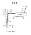
- FIG. 5 is a schematic view showing a state of using an intra-aortic balloon catheter having the conventional configuration by inserting it from the left brachial artery.
- the balloon 2a of the intra-aortic balloon catheter 1a is wound around the inner tube 17 and a guide wire 33 is inserted to the inner tube 17 (second lumen) in advance. Then, by using a Serdinger method, stick a catheter introducer 34 to the left brachial artery 38 and insert the intra-aortic balloon catheter 1a, in which the guide wire 33 is inserted, to the left brachial artery. Note that it is not always necessary to use the catheter introducer 34, and the guide wire 33 and the intra-aortic balloon catheter 1a may be directly inserted to a perforation provided to the left brachial artery 38.
- the blood pressure measurement device measure the blood pressure changes transmitted from the blood inlet 31a (distal end opening of the blood flow channel) to the blood pressure measurement opening (proximal end opening of the blood flow channel) of the connector 25a through blood in the blood flow channel, drive the pump device based on the measurement result, and flow a fluid of a helium gas, etc. into or from the balloon 2a through the fluid flow channel.
- expansion and contraction of the balloon 2a along with the beating of the heart are performed, and the expansion and contraction of the balloon 2a assist the cardiac function.
- the distal end opening 60 of the blood flow channel positions at a lower portion of the descending aorta 40 when inserting it from the arm vessel. Therefore, a blood pressure change caused by the beating of the heart attenuates due to a pressure loss in the descending aorta 40, in which the balloon 2d is inserted, when it reaches to the distal end opening of the blood flow channel, so that the blood pressure change caused by the beating of the heart cannot be measured sufficiently.
- the blood inlet 31a distal end opening of the blood flow channel
- the boundary 50 positions on the proximal end side of the boundary 50 (refer to FIG. 1) with the expansion/contraction portion of the balloon 2a. Therefore, when inserting the catheter from the arm vessel, it is possible to position the distal end opening of the blood flow channel close to the heart, such as an upper portion of the descending aorta 40. As a result, attenuation due to pressure loss hardly arises, and blood pressure changes caused by the beating of the heart can be measured highly accurately with good response.
- the blood inlet was formed to have a circular shape having a size of 2.0 mm 2 on the proximal end side being away
- a skin of a goat (female, weighing about 43 kg) was incised to expose the carotid artery, and a catheter introducer (an inner diameter was 2.4 mm) was inserted to the carotid artery.
- the intra-aortic balloon catheter in which a guide wire (a length in the axial direction of 1500 mm and an outer diameter of 0.5 mm) was inserted, is inserted from the carotid artery of the goat via the catheter introducer. After that, the intra-aortic balloon catheter was pressed to be inserted further, so that the entire balloon was positioned in the descending aorta of the goat.
- the distal end of the balloon positions at a lower portion of the descending aorta and the proximal end of the balloon positions at an upper portion of the descending aorta.
- the connector of the intra-aortic balloon catheter was connected to an intra-aortic balloon catheter drive (the product name is IABP Console 907 and made by Zeon Medical Inc.) having a function as a pump device and a blood pressure measurement device.
- the measured highest blood pressure was 200 mmHg and the lowest blood pressure was 120 mmHg.
- expansion and contraction of the balloon by a helium gas in a setting of operating the pump device along with one beating in every four beating of the heart by using a blood pressure trigger function (a function of controlling the pump device based on the blood pressure measurement result of the blood pressure measurement device) of the intra-aortic balloon catheter drive, expansion and contraction of the balloon along with the beating of the heart could be performed as the setting.
- a blood pressure trigger function a function of controlling the pump device based on the blood pressure measurement result of the blood pressure measurement device
- an intra-aortic balloon catheter of the conventional configuration having the same configuration as that in the intra-aortic balloon catheter used in the example 1 was produced. Then, after taking out the intra-aortic balloon catheter used in the example 1 from the goat, in the same way as in the example 1, the entire balloon of the intra-aortic balloon catheter of the conventional configuration was positioned in the descending aorta of the goat. Next, in the same way as in the example 1, when measuring the blood pressure without performing expansion or contraction, the measured highest blood pressure was 140 mmHg and the lowest blood pressure was 115 mmHg.
- the intra-aortic balloon catheter having the conventional configuration used in the comparative example 1 was taken out from the goat, the bleeding from the carotid artery was stopped, and the incised skin was sutured. Then, a skin of the goat was incised to expose the femoral artery, and a catheter introducer was inserted to the femoral artery. Next, through the catheter introducer, the entire balloon of the intra-aortic balloon catheter having the conventional configuration was positioned in the descending aorta of the goat.
- the distal end of the balloon positions at an upper portion of the descending aorta, and the proximal end of the balloon positions at a lower portion of the descending aorta.
- the measured highest blood pressure was 190 mmHg and the lowest blood pressure was 110 mmHg.
- the example 1 and the reference example 1 exhibit approximately the same blood pressure changes, and expansion and contraction of the balloon along with the beating of the heart could be performed. While, in the comparative example 1, a difference of the highest blood pressure and the lowest blood pressure is small and expansion and contraction of the balloon along with the beating of the heart could not be performed. From the results of the animal experiments using the goat, it can be described that when inserting a intra-aortic balloon catheter having the conventional configuration from the human's arm artery, the blood pressure changes cannot be measured highly accurately with good response comparing with the case of inserting it from the femoral artery, and expansion and contraction of the balloon along with the beating of the heart cannot be performed.
- the intra-aortic balloon catheter of the present invention it can be described that the blood pressure changes can be measured highly accurately with good response, and expansion and contraction of the balloon along with the beating of the heart can be performed even when inserting it from the arm artery.
- the intra-aortic balloon catheter of the present invention as a result of positioning the blood inlet used for measuring the blood pressure on the proximal end side of the boundary with the expansion/contraction portion on the proximal end portion of the balloon, the blood pressure changes can be measured highly accurately with good response even when inserting it from the arm artery, such as the brachial artery.
Landscapes
- Health & Medical Sciences (AREA)
- Heart & Thoracic Surgery (AREA)
- Engineering & Computer Science (AREA)
- Cardiology (AREA)
- Life Sciences & Earth Sciences (AREA)
- Veterinary Medicine (AREA)
- Biomedical Technology (AREA)
- Hematology (AREA)
- Anesthesiology (AREA)
- Animal Behavior & Ethology (AREA)
- General Health & Medical Sciences (AREA)
- Public Health (AREA)
- Mechanical Engineering (AREA)
- Vascular Medicine (AREA)
- Geometry (AREA)
- Medical Informatics (AREA)
- Transplantation (AREA)
- Physics & Mathematics (AREA)
- Child & Adolescent Psychology (AREA)
- Biophysics (AREA)
- Pulmonology (AREA)
- Media Introduction/Drainage Providing Device (AREA)
- External Artificial Organs (AREA)
- Measuring Pulse, Heart Rate, Blood Pressure Or Blood Flow (AREA)
Abstract
The intra-aortic balloon catheter comprises a catheter tube 8a having a fluid flow channel 9a for balloon expansion and a blood flow channel 10a for blood pressure measurement, and a balloon 2a attached to a distal end portion of said catheter tube 8a and having an expansion/contraction portion 3a to be expanded and contracted as a result of flowing a fluid in and out through said fluid flow channel 9a. The balloon 2a is joined with said catheter tube 8a at a distal end portion 4a and proximal end portion 5a of said balloon 2a. A blood inlet 31a is formed on said catheter tube 8a, so that inside of said blood flow channel 10a communicates with outside of said catheter tube 8a. The blood inlet 31a positions on the proximal end side of a boundary 50 with said expansion/contraction portion 3a on the proximal end portion 5a of said balloon 2a.
Description
- The present invention relates to an intra-aortic balloon catheter inserted to patient's aorta to increase a blood flow in the coronary artery, etc. by expanding and contracting the balloon, and particularly relates to an intra-aortic balloon catheter able to be suitably used by being inserted from the artery of an arm.
- An intra-aortic balloon catheter pumping method (hereinafter, referred to as IABP) is known as a treatment method when the cardiac functions decline. IABP is designed to assist cardiac functions by improving the blood pressure in the aorta by the insertion of a balloon catheter in the aorta and expanding and contracting the balloon portion along with the beating of the heart.
- In terms of reducing pain of the patient and saving the trouble of the operator, most of catheters used for heart treatment and inspection are often inserted from the arm vessel, such as the brachial artery and radial artery, to prevent insertion from femoral artery. However, an intra-aortic balloon catheter used in IABP is hard to be formed thinner with a smaller diameter for enabling insertion from an arm vessel due to the structural constraint, so that it is inserted from the femoral artery in most cases.
- However, a technique for forming a thinner intra-aortic balloon catheter has been developed in recent years (for example, refer to the Japanese Unexamined Patent Publication No. 4-343355 and the Japanese Unexamined Patent Publication No. 7-51377). Therefore, production of an intra-aortic balloon catheter formed to be thin to a degree of being able to be inserted from the brachial artery has come to be realized. Therefore, approaches of using an intra-aortic balloon catheter by inserting from the brachial artery have come to be made.
- It has become clear, however, that there arises a disadvantage that changes of blood pressure in the aorta cannot be measured highly accurately with good response when inserting a conventional intra-aortic balloon catheter from the brachial artery comparing with that in the case of inserting it from the femoral artery. When accuracy of measuring blood pressure changes in the aorta is low or a time lag arises in the measurement, expansion and contraction of the balloon along with the beating of the heart become difficult and an effect of assisting the cardiac function is hard to be confirmed.
- The present invention was made in consideration of the above circumstances and has as an object thereof to provide an intra-aortic balloon catheter capable of measuring blood pressure changes in the aorta highly accurately with good response even when being inserted from an arm vessel, such as brachial artery.
- The present inventors have been committed themselves to study for attaining the above objects, found that it is possible to obtain an intra-aortic balloon catheter capable of measuring blood pressure changes in the aorta highly accurately with good response even when being inserted from the arm vessel, such as the brachial artery, by making a blood inlet used for measuring the blood pressure in the aorta conventionally provided near a distal end of the balloon position on the proximal end side of a boundary with an expansion/contraction portion on the proximal end portion of the balloon, and completed the present invention based on the knowledge.
- Namely, according to the present invention, there is provided an intra-aortic balloon catheter comprising
a catheter tube having a fluid flow channel for balloon expansion and a blood flow channel for blood pressure measurement, and
a balloon attached to a distal end portion of the catheter tube and having an expansion/contraction portion to be expanded and contracted as a result of flowing a fluid in and out through the fluid flow channel;
wherein
the balloon is joined with the catheter tube at a distal end portion and proximal end portion of the balloon,
a blood inlet is formed on the catheter tube, so that inside of the blood flow channel communicates with outside of the catheter tube, and
the blood inlet positions on the proximal end side of a boundary with the expansion/contraction portion on the proximal end portion of the balloon. - Preferably, the blood inlet positions on the proximal end side by leaving a distance of 3 to 300 mm from the boundary with the expansion/contraction portion on the proximal end portion of the balloon.
- Preferably, an opening area of the blood inlet is 0.2 to 3 mm2.
- Preferably, the catheter tube comprises an outer tube and an inner tube, wherein at least a part of an outer surface of the inner tube is joined with an inner surface of the outer tube along with the axial direction, so that the fluid flow channel is formed inside of the outer tube, and the blood flow channel is formed in the inner tube;
a distal end of the inner tube protrudes to the distal end side from a distal end of the outer tube;
a distal end portion of the balloon is joined with the distal end portion of the inner tube, and a proximal end portion of the balloon is joined with the distal end portion of the outer tube; and
the blood inlet is formed at a joined portion of the inner tube and outer tube, and the outer tube and inner tube are joined over all circumference of an opening rim of the blood inlet. - Alternately, the catheter tube comprises an outer tube and an inner tube arranged inside of the outer tube along with the axial direction, so that the fluid flow channel is formed inside of the outer tube, and having the blood flow channel is formed inside of the inner tube;
a distal end of the inner tube protrudes to the distal end side from a distal end of the outer tube;
a distal end portion of the balloon is joined with a distal end portion of the inner tube, and a proximal end portion of the balloon is joined with a distal end portion of the outer tube;
a recess is formed on a part of the outer surface of the outer tube;
the inner tube is exposed to the outside of the outer tube at the recess; and
the blood inlet is formed on the inner tube positioning inside of the recess. - In the embodiment, preferably, the inner tube comprises a proximal side inner tube and a distal side inner tube separated from the proximal side tube;
a distal end side opening of the proximal side inner tube positions inside of the recess, and a proximal end side opening of the distal side inner tube positions inside of the recess;
the proximal end side opening and the distal end side opening face to each other by leaving a predetermined distance inside of the recess; and
the distal end side opening of the proximal side inner tube composes the blood inlet. - Note that in the embodiment, the inner tube may be composed of a single tube, and
The blood inlet may be configured by forming an opening on the inner tube wall positioning inside of the recess. - In the present invention, in another embodiment, the catheter tube comprises a two-lumen tube and a balloon supporting tube;
a first lumen composing the fluid flow channel and a second lumen composing the blood flow channel are formed in the two-lumen tube along with the axial direction;
a distal end portion of the two-lumen tube is joined with the balloon supporting tube;
a distal end portion of the balloon supporting tube is joined with a distal end portion of the balloon, and a distal end portion of the two-lumen tube is joined with a proximal end portion of the balloon; and
the blood inlet is formed on a sidewall of the two-lumen tube. - In the embodiment, preferably, a third lumen is formed inside of the balloon supporting tube along with the axial direction, and the third lumen communicates with the second lumen.
- In the present invention, when the balloon is positioned in the aorta, the blood inlet positions in the blood vessel and a proximal end opening of the blood flow channel positions outside of the body.
The intra-aortic balloon catheter of the present invention is preferably used by being inserted from the arm artery. - In the intra-aortic balloon catheter of the present invention, the blood inlet used for blood pressure measurement is positioned on the proximal end side of the boundary with the expansion/contraction portion on the proximal end portion of the balloon. Therefore, even when inserting the intra-aortic balloon catheter of the present invention from the arm vessel, such as the brachial artery, blood pressure changes in the aorta can be measured highly accurately with good response.
- FIG. 1 is a schematic view of an intra-aortic balloon catheter according to a first embodiment of the present invention.
- FIG. 2 is a schematic view of an intra-aortic balloon catheter according to a second embodiment of the present invention.
- FIG. 3 is a schematic view of an intra-aortic balloon catheter according to a third embodiment of the present invention.
- FIG. 4 is a schematic view showing a state of using the intra-aortic balloon catheter shown in FIG. 1 by inserting it from the left brachial artery.
- FIG. 5 is a schematic view showing a state of using an intra-aortic balloon catheter having the conventional configuration by inserting it from the left brachial artery.
- Below, embodiments of the present invention will be explained in detail with reference to the drawings.
- As shown in FIG. 1, an intra-aortic balloon catheter 1a according to a first embodiment of the present invention is used for IABP particularly by being inserted from the arm artery. The intra-aortic balloon catheter 1a comprises a
catheter tube 8a having afluid flow channel 9a for expanding the balloon and ablood flow channel 10a for measuring blood pressure, aballoon 2a attached at the distal end portion of thecatheter tube 8a, and atip 32a joined to the distal end portion of theballoon 2a. Thecatheter tube 8a comprises an outer tube 11a,inner tube 17 and aconnector 25a. - The
balloon 2a has a cylindrical shape and comprises an extraction/contraction portion 3a, which expands and contracts as a result of flowing in and out a fluid through thefluid flow channel 9a of thecatheter 8a. Adistal end portion 4a is formed on the distal end portion side of the extraction/contraction portion 3a, and aproximal end portion 5a is formed on the proximal end side of the extraction/contraction portion 3a. Thedistal end portion 4a and theproximal end portion 5a of theballoon 2a are used as joint margins for attaching theballoon 2a to the distal end portion of thecatheter 8a and do not expand or contract by the fluid. - The extraction/
contraction portion 3a of theballoon 2a is preferably provided with a distal endside taper portion 6a and a proximal endside taper portion 7a respectively having tapered shapes becoming narrower as they extend toward thedistal end portion 4a and theproximal end portion 5a. - An outer diameter and length of the extraction/
contraction portion 3a of theballoon 2a are determined in accordance with an inner volume of the extraction/contraction portion 3a (which affects largely on the effect of assisting cardiac functions) and an inner diameter of the artery. For example, when an inner volume of the extraction/contraction portion 3a is 20 to 50 cc, it is preferable that the outer diameter is 12 to 20 mm and the length along with the axis is 150 to 270 mm. furthermore, a film thickness of the extraction/contraction portion 3a is preferably 30 to 120 pm. Inner diameters of thedistal end portion 4a and theproximal end portion 5a of theballoon 2a are preferably formed to be approximately same as the outer diameter of thecatheter tube 8a, with which they are joined, respectively, and are normally in a range of 0.5 to 3.4 mm. Also, lengths of thedistal end portion 4a and theproximal end portion 5a are preferably 3 to 15 mm. - A material of the
balloon 2a is not particularly limited, but is preferably a material having an excellent antithrombogenicity and flex fatigue resistance, for example, composed of a synthetic resin, such as urethane based elastomer and a copolymer of polyurethane and silicone. A method of forming aballoon 2a is not particularly limited and a dipping molding method and a blow molding method are preferably used. - An outer tube 11a composing the
catheter tube 8a of the intra-aortic balloon catheter 1a has a tubular shape, and afirst lumen 12a is formed therein along the axial direction. Thefirst lumen 12a is used as thefluid flow channel 9a for expanding the balloon of thecatheter tube 8a. An inner diameter and thickness of the outer tube 11a are determined to enable insertion from the arm artery, such as the brachial artery, and secure a sufficient cross-sectional area of the flow channel of thefluid flow channel 9a. It is preferable that the inner diameter is 1.0 to 3.5 mm and the thickness is 0.05 to 0.3 mm, and more preferably, the inner diameter is 1.0 to 2.3 mm and the thickness is 0.05 to 0.15 mm. - Also, a length of the outer tube 11a in the axial direction is set, so that the proximal end positions outside of the body when the distal end is inserted to the aorta and is normally 400 to 800 mm. As a material of composing the outer tube 11a, for example, polyethylene, polypropyrene, polyethylene terephthalate, polyamide, polyvinyl chloride, polyurethane, fluorine resin and other synthetic resins may be used.
- The
inner tube 17 composing thecatheter tube 8a has a tubular shape, and asecond lumen 18 is formed therein along the axial direction. Thesecond lumen 18 of theinner tube 17 is used as theblood flow channel 10a for measuring blood pressure of thecatheter tube 8a. Also, thesecond lumen 18 can be used for leading a guide wire used at the time of inserting the intra-aortic balloon catheter 1a to the patient's aorta. - An inner diameter of the
inner tube 17 is not particularly limited as far as the guide wire can be inserted, but is preferably 0.1 to 1.5 mm. A thickness of theinner tube 17 is not particularly limited as far as it can support theballoon 2a, but is preferably 0.05 to 0.4 mm. Also, a length of theinner tube 17 in the axial direction is normally 550 to 1100 mm. As a material for composing theinner tube 17, a material having a high modulus of bending and a certain degree of flexibility is preferable. Specifically, stainless, tungsten, a nickel-titan alloy and other metals, polyetherether ketone and other synthetic resins, and composite materials obtained by reinforcing a synthetic resin by metal are preferably used. Among them, in terms of having high elasticity and being hard to be deformed permanently, it is preferable to use a nickel-titan alloy exhibiting superelasticity, while in terms of being hard to be broken, it is preferable to use polyetherether ketone. - The
inner tube 17 is arranged inside thefirst lumen 12a of the outer tube 11a and extends along with the axial direction and both ends of theinner tube 17 protrude from the outer tube 11a. At least a part of an inner surface of the outer tube 11a and an outer surface of theinner tube 17 are fixed by adhesive agent, etc. - In the present embodiment, at least at a part of the fixed portion, a
blood inlet 31a penetrating sidewalls of the outer tube 11a andinner tube 17 is formed. Thesecond lumen 18 of theinner tube 17 communicates with outside of the outer tube 11a through theblood inlet 31a. Note that the outer tube 11a and theinner tube 17 are fixed at the whole circumference of the rim of theblood inlet 31a, so that thefirst lumen 12a does not directly communicate with outside of the outer tube 11a through theblood inlet 31a. Also, thefirst lumen 12a does not directly communicate with thesecond lumen 18 through theblood inlet 31a. Note that the both end portions of thesecond lumen 18 also communicates with the outside of the outer tube 11a. Thefirst lumen 12a communicates with the outside of the outer tube 11a only at afluid inlet 27a of aconnector 25a. - A method for composing the
blood inlet 31a is not particularly limited and, for example, a method of fixing theinner tube 17 and outer tube 11a each provided with an opening on its sidewall in advance, so that positions of the opening rims match may be mentioned. Alternately, theblood flow inlet 31a may be formed by fixing theinner tube 17 and the outer tube 11a and, then, forming an opening penetrating side walls of the both at the fixed portion. - A position of forming the
blood inlet 31a (that is, an opening at the distal end of theblood flow channel 10a) is on the proximal end side of aboundary 50 with the extraction/contraction portion 3a on theproximal end portion 5a of theballoon 2a. The position is not particularly limited as far as theblood inlet 31a positions in the vessel when theballoon 2a is placed in the aorta. Specifically, as to the position of theblood inlet 31a, it is preferable that the opening rim on the distal end side of theinlet 31a positions on the proximal end side of theboundary 50 with the extraction/contraction portion 3a of theballoon 2a by leaving a distance of (L=) 3 to 300 mm, and it is more preferable to position on the proximal end side by leaving a distance of (L=) 8 to 100 mm. - When providing the
blood inlet 31a at the position as above, theblood inlet 31a positions in vessel near the heart, such as an upper portion of the descending aorta, inside the aortic arch portion and inside the left subclavian artery, when placing theballoon 2a in the descending aorta. Therefore, changes of blood pressure caused by the beating of the heart can be measured highly accurately with good response. - Note that the
boundary 50 with the extraction/contraction portion 3a on theproximal end portion 5a is, as shown in FIG. 1, a boundary between the proximal endside taper portion 7a of the extraction/contraction portion 3a and theproximal end portion 5a and is a part to be a starting point of the connection margin on theproximal end portion 5a with the outer tube 11a and theinner tube 17. - In the present embodiment shown in FIG. 1, the
blood inlet 31a is formed on the proximal end side of theproximal end portion 5a of theballoon 2a, but it may be formed on theproximal end portion 5a. In that case, theblood inlet 31a is formed at a position, where theinner tube 17, the outer tube 11a and theproximal end portion 5a of theballoon 2a are fixed to be one body, by penetrating their sidewalls. - An opening shape of the
blood inlet 31a is not particularly limited, but a circular shape or an oval shape having a long axis along the center axis of the outer tube 11a are preferable. Also, an opening area of theblood inlet 31a is preferably 0.2 to 3 mm2. When the opening area of theblood inlet 31a is smaller than the 0.2 mm2, taking of blood becomes insufficient at theblood inlet 31a and sufficient measurement of the blood pressure changes becomes difficult. While, when forming ablood inlet 31a having an opening area of exceeding 3 mm2, it is liable that strength of thecatheter tube 8a at the position becomes insufficient. - In terms of keeping airtightness of the
first lumen 12a of the outer tube 11a used as thefluid flow channel 9a for expanding the balloon, the inner surface of the outer tube 11a and the outer surface of theinner tube 17 are preferably flat at least around theblood inlet 31a. - It is sufficient if the inner surface of the outer tube 11a and the outer surface of the
inner tube 17 are fixed at least around theblood inlet 31a, but it is preferable to be fixed over at least 60% of the entire length of the outer tube, and it is more preferable to be fixed over the entire length of the outer tube 11a. When fixing the inner surface of the outer tube 11a and the outer surface of theinner tube 17 over at least 60% of the entire length of the outer tube 11a, the flow channel resistance against a fluid for expanding the balloon becomes low in thefirst lumen 12a, so that expansion and contraction of theballoon 2a can be performed without any delay. - The
connector 25a composing thecatheter tube 8a of the intra-aortic balloon catheter 1a is a molded item provided with a hollow portion having three openings. Namely, theconnector 25a has an outer connection opening 26a to be a connection opening of theinner tube 17 and the outer tube 11a, afluid inlet 27a to be a proximal end opening of thefluid flow channel 9a for balloon expansion, and a bloodpressure measurement opening 28a to be a proximal end opening of theblood flow channel 10a for blood measurement. - A length of the
connector 25a is normally 10 to 150 mm. As a material composing theconnector 25a, ABS (an acrylonitrile butadiene styrene copolymer), polystyrene, polypropyrene, polycarbonate and other thermoplastic resins are preferably used. - In the intra-aortic balloon catheter 1a shown in FIG. 1, the outer tube 11a is connected as a result that the proximal end portion is inserted to the outer tube connection opening 26a of the
connector 25a, and theinner tube 17 is connected as a result that the proximal end portion is inserted from the outer tube connection opening 26a to reach to the bloodpressure measurement opening 28a. - When using the intra-aortic balloon catheter 1a, the
fluid inlet 27a is connected to a pump device for flowing a fluid, such as a helium gas, to and from theballoon 2a, for example, through a tube. The bloodpressure measurement opening 28a is connected to a blood pressure measurement apparatus for measuring the blood pressure at theblood inlet 31a (a distal end opening of theblood flow channel 10a), for example through a tube filled with a normal saline solution. - Also, preferably, the outer
tube connection opening 26a communicates with thefluid inlet 27a of the connector 25 by a linear channel as shown in FIG. 1. When the outertube connection opening 26a communicates with thefluid inlet 27a of the connector 25 by a linear channel, flow channel resistance against the fluid for expanding the balloon becomes low in theconnector 25a, so that expansion and contraction of theballoon 2a can be performed without any delay. - In the intra-aortic balloon catheter 1a shown in FIG. 1, the inner surface of the
proximal end portion 5a of theballoon 2a is joined with the outer surface of the distal end portion of the outer tube 11a, and thedistal end portion 4a of theballoon 2a is joined with the distal end portion of theinner tube 17 via thetip 32a. As a result, theballoon 2a is attached to the outer tube 11a and the inner tube 17 (in other words, the distal end portion of thecatheter tube 8a). As the joining method, heat sealing and adhesive joining, etc. may be mentioned. Due to the joining, inside of theballoon 2a is brought to be in an airtight state except for the distal end opening of the outer tube 11a. - The
tip 32a jointed to the distal end portion of theballoon 2a is a member composed of a relatively soft material and has a function of preventing the distal end portion of theinner tube 17 from perforating the arterial vessel wall. As the material composing thetip 32a, synthetic resin, such as a soft polyvinyl chloride resin, silicone resin, urethane based elastomer, styrene based elastomer, vinyl chloride based elastomer, olefin based elastomer, polyester based elastomer and polyamide based elastomer; or natural rubber, etc. may be used. In terms of the antithronbogenicity, urethane based elastomer is preferably used. - Also, as hardness of the material composing the
tip 32a, the Shore A hardness of 50 to 95 is preferable and the Shore A hardness of 65 to 80 is more preferable. When the Shore A hardness is 95 or higher, it is too hard and causes a possibility of perforating the vessel wall, while when the Shore A hardness is 50 or lower, it is too soft and causes a possibility that the distal end portion of theinner tube 17 staves in thetip 32a to perforate the vessel wall. Note that the Shore hardness here indicates a solid state value measured based on the JIS standard K-7215. - Also, by compounding an X-ray contract agent in the material composing the
tip 32a, thetip 32a can be observed by X-ray fluoroscopy from the outside of the body when inserting the intra-aortic balloon catheter 1a to the vessel. As the X-ray contract agent, metals, such as gold, platinum, tungsten and lead, or metal compounds, such as a titanium oxide, barium sulfite, bismuth trioxide and bismuth subcarbonate may be mentioned. - A shape of the
tip 32a is preferably a tubular shape for a guide wire to penetrate therein. Also, the distal end of thetip 32a is preferably a hemisphere shape. A length of thetip 32a in the axial direction is preferably 5 to 25 mm, and the outer diameter is 1.6 to 3.4 mm, and the inner diameter is preferably 0.1 to 1.5 mm. - As shown in FIG. 2, the intra-aortic balloon catheter 1b of the second embodiment is the same as the intra-aortic balloon catheter 1a of the first embodiment except for the different points explained below. Namely, in the embodiment shown in FIG. 2, instead of the
inner tube 17 shown in FIG. 1, a proximal sideinner tube 19 and adistal side tube 21 are used, and arecess 13 extending along the axis direction is formed on a part of the outer surface of the outer tube 11b. - As shown in FIG. 2, a
catheter tube 8b of the intra-aortic balloon catheter 1b of the second embodiment comprises an outer tube 11b, the proximal sideinner tube 19, the distal sideinner tube 21 and aconnector 25b. The outer tube 11b composing thecatheter tube 8b has a tubular shape, and afirst lumen 12b is formed therein along the axial direction. Thefirst lumen 12b is used as thefluid flow channel 9b for expanding the balloon of thecatheter tube 8b. A size and material of the outer tube 11b may be the same as those of the outer tube 11a of the intra-aortic balloon catheter 1a. - The outer surface of the outer tube 11b is provided with a
recess 13 extending in the axial direction. A length of therecess 13 in the axial direction is normally 1 to 12 mm, a width of the recess is normally 0.1 to 3 mm. A depth of therecess 13 is preferably the same as the outer diameter of the proximal sideinner tube 19 and is normally 0.5 to 2.1 mm. A method of forming therecess 13 on the outer surface of the outer tube 11b is not particularly limited and it can be formed, for example, by pressing a heated pallet against the outer wall of the outer tube 11b. - The proximal side
inner tube 19 composing thecatheter tube 8b of the intra-aortic balloon catheter 1b has a tubular shape, wherein asecond lumen 20 is formed along the axial direction. Thesecond lumen 20 is used as ablood flow channel 10b for measuring the blood pressure of thecatheter tube 8b and also used for leading the guide wire. An inner diameter of the proximal sideinner tube 19 is preferably 0.4 to 1.5 mm, and a thickness of the proximal side inner tube is preferably 0.05 to 0.3 mm. A length of the proximal sideinner tube 19 in the axial direction is normally 100 to 950 mm. As a material composing the proximal sideinner tube 19, the same materials of theinner tube 17 of the intra-aortic balloon catheter 1a of the first embodiment can be used. - The proximal side
inner tube 19 is provided inside thefirst lumen 12b of the outer tube 11b by extending in the axial direction. The proximal end portion of the proximal sideinner tube 19 protrudes from the proximal end of the outer tube 11b, and the distal end portion of the proximal sideinner tube 19 penetrates the sidewall of the outer tube 11b at the proximal end portion of therecess 13 of the outer tube 11b and is in a state of being exposed to the outside. Namely, the distal end opening of the proximal sideinner tube 19 positions outside of thefirst lumen 12b, and thesecond lumen 20 of the proximal sideinner tube 19 communicates with the outside through the distal end opening. Note that, at the position where the distal end portion of the proximal sideinner tube 19 penetrates the outer wall of the outer tube 11b, the outer surface of the proximal sideinner tube 19 and the outer wall of the outer tube 11b are airtightly joined. Also, the proximal end portion of the proximal sideinner tube 19 is connected to theconnector 25b in the same way as theinner tube 17 in the intra-aortic balloon catheter 1a of the first embodiment. - In the intra-aortic balloon catheter 1b of the second embodiment, the entire
second lumen 20 of the proximal sideinner tube 19 composes the entireblood flow channel 10b for measuring the blood pressure, the distal end opening of the proximal sideinner tube 19 is the blood inlet 31b (the distal end opening of theblood flow channel 10b). The position of forming the blood inlet 31b is the same as that in the intra-aortic balloon catheter 1a of the first embodiment. - The distal side
inner tube 21 composing thecatheter tube 8b of the intra-aortic balloon catheter 1b has a tubular shape, and athird lumen 22 is formed therein along the axial direction. Thethird lumen 22 leads a guide wire used at the time of inserting the intra-aortic balloon catheter 1b to the patient's artery. - An inner diameter of the distal side
inner tube 21 is preferably 0.1 to 1.0 mm, and a thickness of the distal sideinner tube 21 is not particularly limited as far as it can support theballoon 2b, but it is preferably 0.05 to 0.4 mm. Also, a length of the distal sideinner tube 21 in the axial direction is normally 150 to 570 mm. As a material composing the distal sideinner tube 21, the same materials as those of theinner tube 17 of the intra-aortic balloon catheter 1a of the first embodiment may be used. - The distal side
inner tube 21 is provided inside thefirst lumen 12b of the outer tube 11b by extending in the axial direction. The distal end portion of the distal sideinner tube 21 protrudes from the distal end of the outer tube 11b, and the proximal end portion of the distal sideinner tube 21 penetrates the sidewall of the outer tube 11b at the distal end portion of therecess 13 of the outer tube 11b to be in a state of being exposed to the outside. Namely, the proximal end opening of the distal sideinner tube 21 positions outside of thefirst lumen 12b, and thethird lumen 22 of the distal sideinner tube 21 communicates with the outside through the proximal end opening. Note that, at the position where the proximal end portion of the distal sideinner tube 21 penetrates the sidewall of the outer tube 11b, the outer surface of the distal sideinner tube 21 and the inner surface of the outer tube 11b are airtightly joined. - In the intra-aortic balloon catheter 1b shown in FIG. 2, the inner surface of the
proximal end portion 5b of theballoon 2b is joined with the outer surface of the distal end portion of the outer tube 11b, and the distal end portion 4b of theballoon 2b is joined with the distal end portion of the distal sideinner tube 21 via thetip 32b. As a result, theballoon 2b is attached to the distal side inner tube 21 (in other words, the distal end portion of thecatheter tube 8b). As a method of joining them, heat sealing and adhesive joining, etc. may be mentioned. Due to the joining, inside of theballoon 2b is brought to be in an airtight state except for the distal end opening of the outer tube 11b. - A distance of the distal end of the proximal side
inner tube 19 and the proximal end of the distal sideinner tube 21 is preferably 1 to 10 mm. When the distance is shorter than 1 mm, blood pressure changes in thethird lumen 22 of the distal sideinner tube 21 affects the blood inlet 31b (the distal end opening of the proximal side inner tube 19) and it may be unable to measure accurate blood pressure. When the distance is longer than 10 mm, strength of thecatheter tube 8b at the position may become insufficient. - An inner diameters of the proximal side
inner tube 19 and that of the distal sideinner tube 21 may be different, particularly, the inner diameter of the distal sideinner tube 21 is preferably smaller than that of the proximal sideinner tube 19 and, it is more preferable that the inner diameter of the distal sideinner tube 21 is 50 to 95% of the inner diameter of the proximal sideinner tube 19. It is necessary that the inner diameter of the proximal sideinner tube 19 has a certain size to transmit the blood pressure changes at the blood inlet 31b to the proximal end opening (a bloodpressure measurement opening 28b) of the proximal sideinner tube 19. On the other hand, it is sufficient if the inner diameter of the distal sideinner tube 21 is made to be able to lead the guide wire, and the distal sideinner tube 21 can be made thinner when the inner diameter is made small, consequently, insertion of the intra-aortic balloon catheter 1b to the patient becomes easier. - A thickness of the proximal side
inner tube 19 and that of the distal sideinner tube 21 may be also different, particularly, the thickness of the proximal sideinner tube 19 is preferably thinner than that of the distal sideinner tube 21, and it is more preferable that the thickness of the proximal sideinner tube 19 is 50 to 95% of the thickness of the distal sideinner tube 21. The distal sideinner tube 21 is required to have a certain thickness to support theballoon 2b. On the other hand, the proximal sideinner tube 19 is not required to be thick since it positions inside the outer tube 11b and theconnector 25b, and when the thickness is made thinner, a cross-sectional area of the flow channel of thefluid flow channel 9b becomes wide and expansion/contraction of theballoon 2b can be performed without any delay. - Note that other configuration of the intra-aortic balloon catheter 1b of the second embodiment is the same as that of the first embodiment, and the same effects as those in the first embodiment can be obtained. Also, in FIG. 1 and FIG. 2, same reference numbers are given to the common members and the explanation thereon are omitted.
- As shown in FIG. 3, a different point of the intra-aortic balloon catheter 1c of a third embodiment from the intra-aortic balloon catheter 1a of the first embodiment is that the
catheter tube 8c comprises a two-lumen tube 14, aballoon supporting tube 24 and aconnector 25c. - The two-
lumen tube 14 composing thecatheter tube 8c of the intra-aortic balloon catheter 1c of the third embodiment has a tubular shape, and afirst lumen 15 and asecond lumen 16 are formed therein in the axial direction. Thefirst lumen 15 is used as afluid flow channel 9c for balloon expanding of thecatheter tube 8c, and thesecond lumen 16 is used as ablood flow channel 10c for blood pressure measuring of thecatheter tube 8c. Thesecond lumen 16 can be used also for leading a guide wire. - An outer diameter of the two-
lumen tube 14 is normally 1.2 to 4.0 mm, and a length of the two-lumen tube 14 in the axial direction is normally 400 to 800 mm. Cross-sectional shapes of thefirst lumen 15 and thesecond lumen 16 of the two-lumen tube 14 are not particularly limited, but an oval shape is preferable. A cross-sectional area of thefirst lumen 15 is preferably 0.6 to 6 mm2, and a cross-sectional area of thesecond lumen 16 is preferably 0.01 to 1.7 mm2. - As a material for composing the two-
lumen tube 14, for example, polyethylene, polypropyrene, polyethylene terephthalate, polyamide, polyvinyl chloride, polyurethane, a fluorine resin or other synthetic resins may be used, and composite materials obtained by reinforcing the synthetic resins by metals may be also used. - A
blood inlet 31c is formed on a sidewall of the two-lumen tube 14, and thesecond lumen 16 communicates with the outside through theblood inlet 31c. A position of forming theblood inlet 31c, that is, a distal end portion of theblood flow channel 10c is the same as that in the intra-aortic balloon catheter 1a of the first embodiment. - Also, an opening shape of the
blood inlet 31c is not particularly limited, but a circular shape and an oval shape along the center axis of the two-lumen tube 14 are preferable. Also, an opening area of theblood inlet 31c is preferably 0.2 to 3 mm2. When the opening area of theblood inlet 31c is smaller than 0.2 mm2, blood cannot be taken in sufficiently at theblood inlet 31c and measurement of the blood pressure changes becomes difficult: While, when ablood inlet 31c having an opening area of exceeding 3 mm2 is provided, strength of thecatheter tube 8c (two-lumen tube 14) at the position may become insufficient. - A
balloon supporting tube 23 composing thecatheter tube 8c of the intra-aortic balloon catheter 1c has a tubular shape, and athird lumen 24 is formed therein along the axial direction. A guide wire used at the time of inserting the intra-aortic balloon catheter 1c to the patient's artery is inserted to thethird lumen 24. An inner diameter of theballoon supporting tube 23 is preferably 0.1 to 1.0 mm, and a thickness of theballoon supporting tube 23 is not particularly limited as far as it can support theballoon tube 2c, but it is preferably 0.05 to 0.4 mm. A length of theballoon tube 23 in the axial direction is approximately the same as the length of theballoon 2c in the axial direction and is normally 150 to 300 mm. As a material composing theballoon supporting tube 23, the same materials as those of theinner tube 17 of the intra-aortic balloon catheter 1a of the first embodiment can be used. - The proximal end portion of the
balloon supporting tube 23 is inserted to thesecond lumen 16 of the two-lumen tube 14 and joined to be airtight against the outside, so that thethird lumen 24 of theballoon supporting tube 23 communicates with thesecond lumen 16 of the two-lumen tube 14. Also, the inner surface of theproximal end portion 5c of theballoon 2c is joined with the outer surface of the distal end portion of the two-lumen tube 14, and thedistal end portion 4c of theballoon 2c is joined with the distal end portion of theballoon supporting tube 23 via thetip 32c. As a result, theballoon 2c is attached to the two-lumen tube 14 and the distal end portion of the balloon supporting tube 23 (in other words, the distal end portion of thecatheter tube 8c). As the joining method, heat sealing and adhesive joining, etc. may be mentioned. Due to the joining, inside of theballoon 2c is brought to be in an airtight state except for the distal end opening of thefirst lumen 15 of the two-lumen tube 14. - The
connector 25c composing thecatheter tube 8c of the intra-aortic balloon catheter 1c of the third embodiment is a molded item provided with afirst duct 29 composing a part of thefluid flow channel 9c for balloon expansion and asecond duct 30 composing a part of theblood flow channel 10c for blood pressure measurement being separate to each other. - The
connector 25c and the two-lumen tube 14 are connected, so that thefirst lumen 15 communicates with thefirst duct 29 and thesecond lumen 16 communicates with thesecond duct 30. As a result of the connection, afluid inlet 27c as a proximal end opening of thefirst duct 29 of theconnector 25c can be used as a proximal end opening of thefluid flow channel 9c for balloon expansion, and ablood measurement opening 28c as a proximal end opening of thesecond duct 30 can be used as a proximal end opening of theblood flow channel 10c for blood pressure measurement. As a material for composing theconnector 25c, the same materials as those of theconnector 25a in the intra-aortic balloon catheter 1a of the first embodiment can be used. - Furthermore, the
first duct 29 of theconnector 25c is preferably configured to be a linear shape. When thefirst duct 29 is a linear duct, the flow channel resistance against the fluid for balloon expansion becomes low in thefirst duct 29, so that expansion and contraction of theballoon 2c can be performed without any delay. - Note that other configuration of the intra-aortic balloon catheter 1c of the third embodiment is the same as that in the first embodiment, and the same effects as those in the first embodiment can be obtained.
- How to use the intra-aortic balloon catheter of the present invention will be explained with reference to the drawings by taking as an example the case of using the intra-aortic balloon catheter 1a of the first embodiment by inserting it from the left brachial artery. FIG. 4 is a schematic view showing a state of using the intra-aortic balloon catheter 1a of the first embodiment according to the intra-aortic balloon catheter of the present invention by inserting it from the left brachial artery, and FIG. 5 is a schematic view showing a state of using an intra-aortic balloon catheter having the conventional configuration by inserting it from the left brachial artery.
- First, the
balloon 2a of the intra-aortic balloon catheter 1a is wound around theinner tube 17 and aguide wire 33 is inserted to the inner tube 17 (second lumen) in advance. Then, by using a Serdinger method, stick acatheter introducer 34 to the leftbrachial artery 38 and insert the intra-aortic balloon catheter 1a, in which theguide wire 33 is inserted, to the left brachial artery. Note that it is not always necessary to use thecatheter introducer 34, and theguide wire 33 and the intra-aortic balloon catheter 1a may be directly inserted to a perforation provided to the leftbrachial artery 38. - Next, push the intra-aortic balloon catheter 1a preceded by the
guide wire 33 to insert further, so that theballoon 2a passes through the left subclavian artery under theleft clavicle 39 and positions in the descendingaorta 40. As shown in FIG. 4, when theentire balloon 2a is positioned inside the descendingaorta 40, remove theguide wire 33 out, connect a pump device (not shown) to the fluid inlet of theconnector 25a, for example, via a tube, and connect a blood pressure measurement device (not shown) to the blood pressure measurement opening, for example, via a tube filled with a normal saline solution. After that, by using the blood pressure measurement device, measure the blood pressure changes transmitted from theblood inlet 31a (distal end opening of the blood flow channel) to the blood pressure measurement opening (proximal end opening of the blood flow channel) of theconnector 25a through blood in the blood flow channel, drive the pump device based on the measurement result, and flow a fluid of a helium gas, etc. into or from theballoon 2a through the fluid flow channel. As a result of the operations as above, expansion and contraction of theballoon 2a along with the beating of the heart are performed, and the expansion and contraction of theballoon 2a assist the cardiac function. - As shown in FIG. 5, in the case of the intra-aortic balloon catheter 1d having the conventional configuration,
wherein a distal end opening 60 of the blood flow channel is provided near the distal end of theballoon 2d, the distal end opening 60 of the blood flow channel positions at a lower portion of the descendingaorta 40 when inserting it from the arm vessel. Therefore, a blood pressure change caused by the beating of the heart attenuates due to a pressure loss in the descendingaorta 40, in which theballoon 2d is inserted, when it reaches to the distal end opening of the blood flow channel, so that the blood pressure change caused by the beating of the heart cannot be measured sufficiently. On the other hand, according to the intra-aortic balloon catheter 1a of the present invention, as shown in FIG. 4, theblood inlet 31a (distal end opening of the blood flow channel) positions on the proximal end side of the boundary 50 (refer to FIG. 1) with the expansion/contraction portion of theballoon 2a. Therefore, when inserting the catheter from the arm vessel, it is possible to position the distal end opening of the blood flow channel close to the heart, such as an upper portion of the descendingaorta 40. As a result, attenuation due to pressure loss hardly arises, and blood pressure changes caused by the beating of the heart can be measured highly accurately with good response. - Note that the present invention is not limited to the above embodiments and may be variously modified within the scope of the present invention.
- Next, the present invention will be explained based on further detailed examples (animal experiments using a goat).
- First, by using an outer tube made by polyamide having a length in the axial direction of 510 mm, an inner diameter of 2.1 mm and a thickness of 0.11 mm, an inner tube made by nickel-titanium alloy having a length in the axial direction of 720 mm, an inner diameter of 0.72 mm and a thickness of 0.11 mm, a balloon made by urethane based elastomer having a length in the axial direction of 200 mm, an inner volume of 30 cc, an outer diameter of 14 mm and a film thickness of 70 pm, a tip made by urethane based elastomer having a length in the axial direction of 10 mm, an inner diameter of 0.72 mm and an outer diameter of 2.1mm and a connector made by ABS; an intra-aortic balloon catheter having the same configuration explained as the first embodiment of the present invention was produced. Note that the blood inlet was formed to have a circular shape having a size of 2.0 mm2 on the proximal end side being away by 10 mm from the expansion/contraction portion of the balloon.
- Then, a skin of a goat (female, weighing about 43 kg) was incised to expose the carotid artery, and a catheter introducer (an inner diameter was 2.4 mm) was inserted to the carotid artery. Next, the intra-aortic balloon catheter, in which a guide wire (a length in the axial direction of 1500 mm and an outer diameter of 0.5 mm) was inserted, is inserted from the carotid artery of the goat via the catheter introducer. After that, the intra-aortic balloon catheter was pressed to be inserted further, so that the entire balloon was positioned in the descending aorta of the goat. Note that when inserting the intra-aortic balloon catheter from the carotid artery of the goat to position the entire balloon in the descending aorta, in the same way as in the case of inserting from the human's arm artery, the distal end of the balloon positions at a lower portion of the descending aorta and the proximal end of the balloon positions at an upper portion of the descending aorta.
- Then, the connector of the intra-aortic balloon catheter was connected to an intra-aortic balloon catheter drive (the product name is IABP Console 907 and made by Zeon Medical Inc.) having a function as a pump device and a blood pressure measurement device. Next, when measuring the blood pressure by operating the blood pressure measurement device in a state of not driving the pump device of the intra-aortic balloon catheter drive, the measured highest blood pressure was 200 mmHg and the lowest blood pressure was 120 mmHg. After that, when performing expansion and contraction of the balloon by a helium gas in a setting of operating the pump device along with one beating in every four beating of the heart by using a blood pressure trigger function (a function of controlling the pump device based on the blood pressure measurement result of the blood pressure measurement device) of the intra-aortic balloon catheter drive, expansion and contraction of the balloon along with the beating of the heart could be performed as the setting.
- First, other than not providing a blood inlet, an intra-aortic balloon catheter of the conventional configuration having the same configuration as that in the intra-aortic balloon catheter used in the example 1 was produced. Then, after taking out the intra-aortic balloon catheter used in the example 1 from the goat, in the same way as in the example 1, the entire balloon of the intra-aortic balloon catheter of the conventional configuration was positioned in the descending aorta of the goat. Next, in the same way as in the example 1, when measuring the blood pressure without performing expansion or contraction, the measured highest blood pressure was 140 mmHg and the lowest blood pressure was 115 mmHg. After that, by using the blood pressure trigger function, in a setting of operating the pump device along with one beating in every four beating of the heart, expansion and contraction of the balloon by a helium gas were attempted, however, because the measured blood pressure changes were not sufficient, the blood pressure trigger function did not work and expansion and contraction of the balloon along with the beating of the heart could not be performed.
- First, the intra-aortic balloon catheter having the conventional configuration used in the comparative example 1 was taken out from the goat, the bleeding from the carotid artery was stopped, and the incised skin was sutured. Then, a skin of the goat was incised to expose the femoral artery, and a catheter introducer was inserted to the femoral artery. Next, through the catheter introducer, the entire balloon of the intra-aortic balloon catheter having the conventional configuration was positioned in the descending aorta of the goat.
- Note that when inserting the intra-aortic balloon catheter of having the conventional configuration from the femoral artery of the goat and positioning the entire balloon in the descending aorta, in the same way as the case of inserting it from the human's femoral artery, the distal end of the balloon positions at an upper portion of the descending aorta, and the proximal end of the balloon positions at a lower portion of the descending aorta. After that, in the same way as in the example 1, when measuring the blood pressure without performing expansion and contraction of the balloon, the measured highest blood pressure was 190 mmHg and the lowest blood pressure was 110 mmHg. Then, when performing expansion and contraction of the balloon by a helium gas by using the blood pressure trigger function of the intra-aortic balloon catheter drive in a setting of operating the pump device along with one beating in every four beating of the heart, expansion and contraction of the balloon with the beating of the heart as the setting could be performed.
- The highest blood pressure and the lowest blood pressure measured in the example 1, comparative example 1 and reference example 1, a difference of the highest blood pressure and the lowest blood pressure, and availability of expansion and contraction of the balloon along with the beating of the heart were listed in Table 1.
-
[Table 1] Highest Blood Pressure (mmHg) Lowest Blood Pressure (mmHg) Difference of Highest and Lowest Blood Pressures (mmHg) Availability of Expansion/ Contraction of Balloon along with Heartbeat Example 1 200 120 80 Good Comparative Example 1 140 115 25 No Good Reference Example 1 190 110 80 Good - When referring to Table 1, the example 1 and the reference example 1 exhibit approximately the same blood pressure changes, and expansion and contraction of the balloon along with the beating of the heart could be performed. While, in the comparative example 1, a difference of the highest blood pressure and the lowest blood pressure is small and expansion and contraction of the balloon along with the beating of the heart could not be performed. From the results of the animal experiments using the goat, it can be described that when inserting a intra-aortic balloon catheter having the conventional configuration from the human's arm artery, the blood pressure changes cannot be measured highly accurately with good response comparing with the case of inserting it from the femoral artery, and expansion and contraction of the balloon along with the beating of the heart cannot be performed. On the other hand, by using the intra-aortic balloon catheter of the present invention, it can be described that the blood pressure changes can be measured highly accurately with good response, and expansion and contraction of the balloon along with the beating of the heart can be performed even when inserting it from the arm artery.
- As explained above, according to the intra-aortic balloon catheter of the present invention, as a result of positioning the blood inlet used for measuring the blood pressure on the proximal end side of the boundary with the expansion/contraction portion on the proximal end portion of the balloon, the blood pressure changes can be measured highly accurately with good response even when inserting it from the arm artery, such as the brachial artery.
Claims (10)
- An intra-aortic balloon catheter comprising
a catheter tube having a fluid flow channel for balloon expansion and a blood flow channel for blood pressure measurement, and
a balloon attached to a distal end portion of said catheter tube and having an expansion/contraction portion to be expanded and contracted as a result of flowing a fluid in and out through said fluid flow channel;
wherein
said balloon is joined with said catheter tube at a distal end portion and proximal end portion of said balloon,
a blood inlet is formed on said catheter tube, so that inside of said blood flow channel communicates with outside of said catheter tube, and
said blood inlet positions on the proximal end side of a boundary with said expansion/contraction portion on the proximal end portion of said balloon. - The intra-aortic balloon catheter as set forth in claim 1, wherein said blood inlet positions on the proximal end side by leaving a distance of 3 to 300 mm from the boundary with said expansion/contraction portion on the proximal end portion of said balloon.
- The intra-aortic balloon catheter as set forth in claim 1, wherein an opening area of said blood inlet is 0.2 to 3 mm2.
- The intra-aortic balloon catheter as set forth in claim 1, wherein
said catheter tube comprises an outer tube and an inner tube, wherein at least a part of an outer surface of the inner tube is joined with an inner surface of said outer tube along with the axial direction, so that said fluid flow channel is formed inside of said outer tube, and said blood flow channel is formed in the inner tube;
a distal end of said inner tube protrudes to the distal end side from a distal end of said outer tube;
a distal end portion of said balloon is joined with the distal end portion of said inner tube, and a proximal end portion of said balloon is joined with the distal end portion of said outer tube; and
said blood inlet is formed at a joined portion of said inner tube and outer tube, and said outer tube and inner tube are joined over all circumference of an opening rim of said blood inlet. - The intra-aortic balloon catheter as set forth in claim 1, wherein
said catheter tube comprises an outer tube and an inner tube arranged inside of said outer tube along with the axial direction, so that said fluid flow channel is formed inside of said outer tube, and said blood flow channel is formed inside of the inner tube;
a distal end of said inner tube protrudes to the distal end side than a distal end of said outer tube;
a distal end portion of said balloon is joined with a distal end portion of said inner tube, and a proximal end portion of said balloon is joined with a distal end portion of said outer tube;
a recess is formed on a part of the outer surface of said outer tube;
said inner tube is exposed to the outside of said outer tube at said recess; and
said blood inlet is formed on said inner tube positioning inside of said recess. - The intra-aortic balloon catheter as set forth in claim 5, wherein:said inner tube comprises a proximal side inner tube and a distal side inner tube separated from the proximal side tube;a distal end side opening of said proximal side inner tube positions inside of said recess, and a proximal end side opening of said distal side inner tube positions inside of said recess;the proximal end side opening and the distal end side opening face to each other by leaving a predetermined distance inside of said recess; andthe distal end side opening of said proximal side inner tube composes said blood inlet.
- The intra-aortic balloon catheter as set forth in claim 1, wherein:said catheter tube comprises a two-lumen tube and a balloon supporting tube;a first lumen composing said fluid flow channel and a second lumen composing said blood flow channel are formed in said two-lumen tube along with the axial direction;a distal end portion of said two-lumen tube is joined with said balloon supporting tube;a distal end portion of said balloon supporting tube is joined with a distal end portion of said balloon, and a distal end portion of said two-lumen tube is joined with a proximal end portion of said balloon; andsaid blood inlet is formed on a sidewall of said two-lumen tube.
- The intra-aortic balloon catheter as set forth in claim 7, wherein a third lumen is formed inside of said balloon supporting tube along with the axial direction, and the third lumen communicates with said second lumen.
- The intra-aortic balloon catheter as set forth in claim 1, configured that, when said balloon is positioned in an aorta, said blood inlet positions in a blood vessel and a proximal end opening of said blood flow channel positions outside of the body.
- The intra-aortic balloon catheter as set forth in claim 1 used by being inserted from the arm artery.
Applications Claiming Priority (2)
| Application Number | Priority Date | Filing Date | Title |
|---|---|---|---|
| JP2003283202 | 2003-07-30 | ||
| PCT/JP2004/010839 WO2005011794A1 (en) | 2003-07-30 | 2004-07-29 | Balloon catheter for main artery |
Publications (1)
| Publication Number | Publication Date |
|---|---|
| EP1674126A1 true EP1674126A1 (en) | 2006-06-28 |
Family
ID=34113805
Family Applications (1)
| Application Number | Title | Priority Date | Filing Date |
|---|---|---|---|
| EP04771052A Withdrawn EP1674126A1 (en) | 2003-07-30 | 2004-07-29 | Intra-aortic balloon catheter |
Country Status (5)
| Country | Link |
|---|---|
| US (1) | US20070005010A1 (en) |
| EP (1) | EP1674126A1 (en) |
| JP (1) | JPWO2005011794A1 (en) |
| CN (1) | CN1856337A (en) |
| WO (1) | WO2005011794A1 (en) |
Families Citing this family (29)
| Publication number | Priority date | Publication date | Assignee | Title |
|---|---|---|---|---|
| JP2009530041A (en) | 2006-03-23 | 2009-08-27 | ザ・ペン・ステート・リサーチ・ファンデーション | Cardiac assist device with expandable impeller pump |
| US9375217B2 (en) * | 2006-07-18 | 2016-06-28 | Boston Scientific Scimed, Inc. | Catheterizing body lumens |
| FR2916287B1 (en) * | 2007-05-15 | 2014-06-27 | Thales Sa | METHOD FOR TRACING A TRACK PORTION OF AN AIRCRAFT COMPRISING A CONSTANT RING CIRCLE ARC |
| WO2012013662A1 (en) * | 2010-07-26 | 2012-02-02 | Steerable Instruments Bvba | Capillary tube assembly |
| WO2012110598A1 (en) * | 2011-02-16 | 2012-08-23 | Acrostak Corp Bvi, Tortola | Narrow profile catheter with deformation-resistive guidewire lumen |
| US8923973B2 (en) | 2011-11-10 | 2014-12-30 | Rainbow Medical Ltd. | Blood flow control element |
| US9386991B2 (en) | 2012-02-02 | 2016-07-12 | Rainbow Medical Ltd. | Pressure-enhanced blood flow treatment |
| DE102013008159A1 (en) | 2012-05-14 | 2013-11-14 | Thoratec Corporation | Sheath system for catheter pump |
| DE102013008168A1 (en) | 2012-05-14 | 2013-11-14 | Thoratec Corporation | Impeller for catheter pump |
| US9446179B2 (en) | 2012-05-14 | 2016-09-20 | Thoratec Corporation | Distal bearing support |
| KR20150016970A (en) * | 2012-06-05 | 2015-02-13 | 머핀 인코포레이티드 | Catheter systems and methods useful for cell therapy |
| US9358329B2 (en) | 2012-07-03 | 2016-06-07 | Thoratec Corporation | Catheter pump |
| CN103656836B (en) * | 2012-09-19 | 2015-10-14 | 复旦大学附属华山医院 | Magnetic compatibility can not demulsification glueballs ductus bursae |
| US20140257359A1 (en) * | 2013-03-11 | 2014-09-11 | St. Jude Medical Puerto Rico Llc | Temporary sealing device with blood flashback for vessel location |
| JP6530367B2 (en) | 2013-03-13 | 2019-06-12 | ティーシーワン エルエルシー | Fluid outlet / inlet system |
| WO2015160980A1 (en) | 2014-04-15 | 2015-10-22 | Thoratec Corporation | Heart pump providing adjustable out flow |
| US10583232B2 (en) | 2014-04-15 | 2020-03-10 | Tc1 Llc | Catheter pump with off-set motor position |
| US20170007754A1 (en) * | 2015-07-06 | 2017-01-12 | Cook Medical Technologies Llc | Endovascular compliance assembly |
| US11160970B2 (en) | 2016-07-21 | 2021-11-02 | Tc1 Llc | Fluid seals for catheter pump motor assembly |
| US11351355B2 (en) * | 2017-10-19 | 2022-06-07 | Datascope Corporation | Devices for pumping blood, related systems, and related methods |
| US10918773B2 (en) * | 2018-03-26 | 2021-02-16 | Tci Llc | Collapsible and self-expanding cannula for a percutaneous heart pump and method of manufacturing |
| JP7091770B2 (en) * | 2018-03-28 | 2022-06-28 | 日本ゼオン株式会社 | Intra-aortic balloon catheter |
| CN111773522A (en) * | 2020-07-02 | 2020-10-16 | 武汉开阖同立医疗科技有限公司 | A slow-release controlled aortic counterpulsation balloon catheter |
| WO2022261438A1 (en) * | 2021-06-10 | 2022-12-15 | The United States Government As Represented By The Department Of Veterans Affairs | Intra-aortic balloon pump |
| CN115282465B (en) * | 2022-08-16 | 2023-10-10 | 心擎医疗(苏州)股份有限公司 | External blood pump system with online real-time feedback control based on blood pressure |
| US20240082564A1 (en) * | 2022-09-13 | 2024-03-14 | Nupulsecv, Inc. | Intra-aortic balloon pump assembly |
| US20240082565A1 (en) * | 2022-09-13 | 2024-03-14 | Nupulsecv, Inc. | Intra-aortic balloon pump assembly with pressure sensor |
| CN115920211A (en) * | 2022-12-12 | 2023-04-07 | 浙江巴泰医疗科技有限公司 | A tip structure, a balloon dilatation catheter comprising the tip structure, and a preparation method thereof |
| CN116212191A (en) * | 2023-02-28 | 2023-06-06 | 丰凯利医疗器械(上海)有限公司 | Multilumen Tubing and Interventional Catheters |
Family Cites Families (6)
| Publication number | Priority date | Publication date | Assignee | Title |
|---|---|---|---|---|
| JPS6092773A (en) * | 1983-10-28 | 1985-05-24 | 泉工医科工業株式会社 | Balloon catheter for balloon pumping in lung artery |
| US4892519A (en) * | 1987-12-03 | 1990-01-09 | Advanced Cardiovascular Systems, Inc. | Steerable perfusion dilatation catheter |
| JP2998504B2 (en) * | 1993-08-13 | 2000-01-11 | 日本ゼオン株式会社 | Balloon catheter |
| JP2000051361A (en) * | 1998-08-11 | 2000-02-22 | Sumitomo Bakelite Co Ltd | Dilating balloon catheter |
| US6679861B2 (en) * | 1999-10-04 | 2004-01-20 | K.K. Vayu | Occlusion catheter for the ascending aorta |
| JP4955154B2 (en) * | 2000-05-29 | 2012-06-20 | 株式会社ヴァーユ | Balloon catheter |
-
2004
- 2004-07-29 US US10/566,298 patent/US20070005010A1/en not_active Abandoned
- 2004-07-29 WO PCT/JP2004/010839 patent/WO2005011794A1/en not_active Ceased
- 2004-07-29 EP EP04771052A patent/EP1674126A1/en not_active Withdrawn
- 2004-07-29 CN CNA2004800277095A patent/CN1856337A/en active Pending
- 2004-07-29 JP JP2005512512A patent/JPWO2005011794A1/en not_active Withdrawn
Non-Patent Citations (1)
| Title |
|---|
| See references of WO2005011794A1 * |
Also Published As
| Publication number | Publication date |
|---|---|
| WO2005011794A1 (en) | 2005-02-10 |
| US20070005010A1 (en) | 2007-01-04 |
| JPWO2005011794A1 (en) | 2007-09-27 |
| CN1856337A (en) | 2006-11-01 |
Similar Documents
| Publication | Publication Date | Title |
|---|---|---|
| US20070005010A1 (en) | Intra-aortic balloon catheter | |
| EP1545686B1 (en) | Intra-aortic balloon catheter having a collapsible variable diameter inner tube | |
| US5876426A (en) | System and method of providing a blood-free interface for intravascular light delivery | |
| US5084033A (en) | Arterial cannula tip and method of manufacture | |
| US5695467A (en) | Intra aortic balloon pumping catheter | |
| EP0351734B1 (en) | Balloon catheter | |
| JPH0838618A (en) | Balloon catheter for expanding body cavity and method for manufacturing the same | |
| WO2005094917A1 (en) | Balloon catheter | |
| JPH08215312A (en) | Balloon catheter | |
| EP1557193B1 (en) | Balloon catheter | |
| JP4900242B2 (en) | Aortic balloon pumping set | |
| JP2002355313A (en) | Catheter tubes and balloon catheters | |
| JP2004275337A (en) | Balloon catheter and method of manufacturing the same | |
| JP2004261299A (en) | Balloon catheter | |
| JP2016189921A (en) | Balloon catheter for IABP | |
| JP2002291900A (en) | Medical device and method of manufacturing the same | |
| JPH11332992A (en) | Catheter holder | |
| JP4492182B2 (en) | Intra-aortic balloon catheter | |
| JP3654355B2 (en) | Catheter tube set | |
| ITMI940199A1 (en) | CATHETER AND PROCEDURE FOR ITS MANUFACTURE | |
| JPH0416676Y2 (en) | ||
| JPH0531194A (en) | Balloon catheter | |
| JP4492183B2 (en) | Balloon catheter | |
| JP2582505Y2 (en) | Sheath for catheter tube insertion | |
| JPH0994297A (en) | Guiding catheter |
Legal Events
| Date | Code | Title | Description |
|---|---|---|---|
| PUAI | Public reference made under article 153(3) epc to a published international application that has entered the european phase |
Free format text: ORIGINAL CODE: 0009012 |
|
| 17P | Request for examination filed |
Effective date: 20060202 |
|
| AK | Designated contracting states |
Kind code of ref document: A1 Designated state(s): AT DE ES FR GB IT |
|
| DAX | Request for extension of the european patent (deleted) | ||
| RBV | Designated contracting states (corrected) |
Designated state(s): AT DE ES FR GB IT |
|
| STAA | Information on the status of an ep patent application or granted ep patent |
Free format text: STATUS: THE APPLICATION HAS BEEN WITHDRAWN |
|
| 18W | Application withdrawn |
Effective date: 20081217 |