EP1673159B1 - Canne d'injection et procede aerodynamique de reduction de bruit destine aux groupes compresseurs-condenseurs refroidis a l'air - Google Patents
Canne d'injection et procede aerodynamique de reduction de bruit destine aux groupes compresseurs-condenseurs refroidis a l'air Download PDFInfo
- Publication number
- EP1673159B1 EP1673159B1 EP04779003A EP04779003A EP1673159B1 EP 1673159 B1 EP1673159 B1 EP 1673159B1 EP 04779003 A EP04779003 A EP 04779003A EP 04779003 A EP04779003 A EP 04779003A EP 1673159 B1 EP1673159 B1 EP 1673159B1
- Authority
- EP
- European Patent Office
- Prior art keywords
- sparger
- fluid
- disk
- steam
- fluid flow
- Prior art date
- Legal status (The legal status is an assumption and is not a legal conclusion. Google has not performed a legal analysis and makes no representation as to the accuracy of the status listed.)
- Expired - Lifetime
Links
- 238000000034 method Methods 0.000 title claims abstract description 15
- 239000012530 fluid Substances 0.000 claims abstract description 84
- 230000003247 decreasing effect Effects 0.000 claims description 5
- 230000009467 reduction Effects 0.000 abstract description 8
- XLYOFNOQVPJJNP-UHFFFAOYSA-N water Substances O XLYOFNOQVPJJNP-UHFFFAOYSA-N 0.000 description 15
- 239000007921 spray Substances 0.000 description 7
- 230000001143 conditioned effect Effects 0.000 description 6
- 230000007423 decrease Effects 0.000 description 6
- 238000013461 design Methods 0.000 description 5
- 238000010586 diagram Methods 0.000 description 4
- 230000005611 electricity Effects 0.000 description 3
- 238000004519 manufacturing process Methods 0.000 description 3
- 230000008569 process Effects 0.000 description 3
- 239000000498 cooling water Substances 0.000 description 2
- 230000001419 dependent effect Effects 0.000 description 2
- 238000012423 maintenance Methods 0.000 description 2
- 238000002156 mixing Methods 0.000 description 2
- 230000035515 penetration Effects 0.000 description 2
- 238000010248 power generation Methods 0.000 description 2
- 230000000750 progressive effect Effects 0.000 description 2
- 238000011084 recovery Methods 0.000 description 2
- 230000008439 repair process Effects 0.000 description 2
- 238000000926 separation method Methods 0.000 description 2
- 239000007787 solid Substances 0.000 description 2
- 230000000153 supplemental effect Effects 0.000 description 2
- 238000011144 upstream manufacturing Methods 0.000 description 2
- 238000003466 welding Methods 0.000 description 2
- 238000006243 chemical reaction Methods 0.000 description 1
- 238000009833 condensation Methods 0.000 description 1
- 230000005494 condensation Effects 0.000 description 1
- 230000003750 conditioning effect Effects 0.000 description 1
- 238000007796 conventional method Methods 0.000 description 1
- 238000001704 evaporation Methods 0.000 description 1
- 230000008020 evaporation Effects 0.000 description 1
- 230000003993 interaction Effects 0.000 description 1
- 238000003754 machining Methods 0.000 description 1
- 238000012986 modification Methods 0.000 description 1
- 230000004048 modification Effects 0.000 description 1
- 230000002250 progressing effect Effects 0.000 description 1
- 238000004064 recycling Methods 0.000 description 1
- 239000013589 supplement Substances 0.000 description 1
- 230000007704 transition Effects 0.000 description 1
- 238000009834 vaporization Methods 0.000 description 1
- 230000008016 vaporization Effects 0.000 description 1
Images


Classifications
-
- F—MECHANICAL ENGINEERING; LIGHTING; HEATING; WEAPONS; BLASTING
- F01—MACHINES OR ENGINES IN GENERAL; ENGINE PLANTS IN GENERAL; STEAM ENGINES
- F01D—NON-POSITIVE DISPLACEMENT MACHINES OR ENGINES, e.g. STEAM TURBINES
- F01D25/00—Component parts, details, or accessories, not provided for in, or of interest apart from, other groups
- F01D25/30—Exhaust heads, chambers, or the like
-
- B—PERFORMING OPERATIONS; TRANSPORTING
- B01—PHYSICAL OR CHEMICAL PROCESSES OR APPARATUS IN GENERAL
- B01F—MIXING, e.g. DISSOLVING, EMULSIFYING OR DISPERSING
- B01F25/00—Flow mixers; Mixers for falling materials, e.g. solid particles
- B01F25/30—Injector mixers
- B01F25/31—Injector mixers in conduits or tubes through which the main component flows
- B01F25/313—Injector mixers in conduits or tubes through which the main component flows wherein additional components are introduced in the centre of the conduit
- B01F25/3132—Injector mixers in conduits or tubes through which the main component flows wherein additional components are introduced in the centre of the conduit by using two or more injector devices
- B01F25/31322—Injector mixers in conduits or tubes through which the main component flows wherein additional components are introduced in the centre of the conduit by using two or more injector devices used simultaneously
-
- B—PERFORMING OPERATIONS; TRANSPORTING
- B01—PHYSICAL OR CHEMICAL PROCESSES OR APPARATUS IN GENERAL
- B01F—MIXING, e.g. DISSOLVING, EMULSIFYING OR DISPERSING
- B01F25/00—Flow mixers; Mixers for falling materials, e.g. solid particles
- B01F25/30—Injector mixers
- B01F25/31—Injector mixers in conduits or tubes through which the main component flows
- B01F25/313—Injector mixers in conduits or tubes through which the main component flows wherein additional components are introduced in the centre of the conduit
- B01F25/3133—Injector mixers in conduits or tubes through which the main component flows wherein additional components are introduced in the centre of the conduit characterised by the specific design of the injector
- B01F25/31331—Perforated, multi-opening, with a plurality of holes
- B01F25/313311—Porous injectors
-
- F—MECHANICAL ENGINEERING; LIGHTING; HEATING; WEAPONS; BLASTING
- F01—MACHINES OR ENGINES IN GENERAL; ENGINE PLANTS IN GENERAL; STEAM ENGINES
- F01K—STEAM ENGINE PLANTS; STEAM ACCUMULATORS; ENGINE PLANTS NOT OTHERWISE PROVIDED FOR; ENGINES USING SPECIAL WORKING FLUIDS OR CYCLES
- F01K9/00—Plants characterised by condensers arranged or modified to co-operate with the engines
- F01K9/04—Plants characterised by condensers arranged or modified to co-operate with the engines with dump valves to by-pass stages
-
- F—MECHANICAL ENGINEERING; LIGHTING; HEATING; WEAPONS; BLASTING
- F22—STEAM GENERATION
- F22G—SUPERHEATING OF STEAM
- F22G5/00—Controlling superheat temperature
- F22G5/12—Controlling superheat temperature by attemperating the superheated steam, e.g. by injected water sprays
- F22G5/123—Water injection apparatus
Definitions
- the sparger and the noise abatement method described herein make known an apparatus and method for reducing the aerodynamic resistance presented by a fluid pressure reduction device in a duct. More specifically, a sparger is disclosed having an aerodynamic profile that significantly reduces the fluid resistance within a turbine exhaust duct of an air-cooled condensing system.
- Modem power generating stations or power plants use steam turbines to generate power.
- steam generated in a boiler is fed to a turbine where the steam expands as it turns the turbine to generate work to create electricity. Occasional maintenance and repair of the turbine system is required. When the turbine is taken out of service, it is typically more economical to continue boiler operation rather than shutting the boiler down during turbine repair.
- the power plant is commonly designed with supplemental piping and valves that circumvent the steam turbine and redirect the steam to a recovery circuit that reclaims the steam for further use.
- the supplemental piping is conventionally known as a turbine bypass circuit.
- Typical air-cooled condensers have temperature and pressure limits. Because the steam from the turbine bypass circuit or bypass steam has not produced work through the turbine, its pressure and temperature is greater than the turbine-exhausted steam. As a result, the higher temperature and pressure of the bypass steam must be conditioned or reduced prior to entering the air-cooled condenser to avoid damage to the condenser. Cooling water is typically injected into the bypass steam to moderate the steam's temperature. To control the bypass steam's pressure prior to entering the condenser, control valves, and more specifically, fluid pressure reduction devices, commonly referred to as spargers, are used. The spargers are restrictive devices that reduce fluid pressure by transferring and absorbing fluid energy contained in the bypass steam.
- Typical spargers are constructed of a cylindrical, hollow housing or a perforated tube that protrudes into the turbine exhaust duct.
- the bypass steam is received in the hollow housing and transferred by the sparger into the duct through a multitude of fluid passageways to the exterior surface.
- the sparger reduces the flow and the pressure of the incoming bypass steam and any residual cooling water within acceptable levels prior to entering the air-cooled condenser.
- multiple spargers are mounted into the turbine exhaust duct. Because of space limitations within the duct, the spargers are generally spaced very closely and may impede the flow of exhaust steam from the steam turbine into the air-cooled condenser. Steam turbines are designed to exhaust into a specific back-pressure within the turbine exhaust duct to optimize their operation. The back-pressure within the turbine exhaust duct is directly related to the aerodynamic resistance or drag presented by the spargers. Conventional spargers used in modem power plants do not minimize the drag within the duct and subsequently can reduce the efficiency and output of turbine.
- the present sparger and aerodynamic noise abatement method may be used to reduce the aerodynamic resistance presented by fluid pressure reduction device and more specifically, a noise abatement device is disclosed having at least one sparger with a cross-sectional profile that significantly reduces the fluid resistance and back-pressure within the turbine exhaust duct of an air-cooled condensing system that may be used in a power plant.
- the aerodynamic sparger is assembled from elliptically-shaped, stacked disks along a longitudinal axis that define flow passages connecting a plurality of inlets to the exterior outlets.
- the stacked disks create restrictive passageways to induce axial and lateral mixing of the fluid in staged pressure reductions that decrease fluid pressure and subsequently reduce the aerodynamic noise within the sparger.
- the aerodynamic sparger is fashioned from a stack of disks with tortuous paths positioned in the top surface of each disk which are assembled to create fluid passageways between the inlet and outlets of the sparger.
- the tortuous paths permit fluid flow through the spargers and produce a reduction in fluid pressure.
- a method to substantially reduce aerodynamic resistance presented by a noise abatement device within the turbine exhaust duct of an air-cooled condenser is established.
- FIG. 1A a block diagram of a steam turbine bypass circuit of a power plant is illustrated.
- the power generation process begins at the boiler 10. Energy conversion in the boiler 10 generates heat. The heat transforms the water pumped from a feedwater tank 26, using a feedwater pump 28, into steam. The feedwater tank 26 serves as a reservoir for the water-steam circuit.
- a series of steam lines or pipes 17 directs the steam from the boiler 10 to drive a steam turbine 11 for power generation.
- a rotating shaft (not shown) in the steam turbine 11 is connected to a generator 15. As the generator 15 turns, electricity is produced.
- the turbine-exhausted steam 36 from the steam turbine 11 is then transferred through a turbine exhaust duct 38 to an air-cooled condenser 16 where the steam is converted back to water.
- the recovered water 58 is pumped by the condensate pump 22 back to the feedwater tank 26, thus completing the closed water-steam circuit for the turbine-exhausted steam 36.
- the steam turbine 11 depicted in Figure 1A has three progressive stages: a High pressure (HP) stage 12, an Intermediate Pressure (IP) stage 13, and a Low pressure (LP) stage 14. Each progressive turbine stage is designed to use the steam with decreasing temperature and pressure.
- HP High pressure
- IP Intermediate Pressure
- LP Low pressure
- Each progressive turbine stage is designed to use the steam with decreasing temperature and pressure.
- the steam turbine 11 is not always operational. For economic reasons, the boiler 10 is rarely shutdown. Therefore, another means to condition the steam must be available when the steam turbine 11 is not available.
- a turbine bypass circuit 19 is typically used to accomplish this function.
- a turbine bypass circuit 19 circumvents the steam turbine loop described above.
- Numerous bypass schemes are typically employed in a power plant. Depending on the origin of the steam, whether it is from the HP stage 12 or IP stage 13, and the operational stage of the plant, different techniques are required to moderate the steam prior to entering the air-cooled condenser 16.
- the HP bypass scheme illustrated in Figure 1A is employed during turbine shutdown and adequately illustrates the operating conditions that require the present aerodynamic noise abatement device.
- the turbine bypass circuit 19 receives steam from the piping 29 that supplies steam to the HP stage 12 of the steam turbine 11, thus bypassing the steam turbine 11. For example, during these maintenance periods, an HP inlet valve 27 is operated in opposite fashion of the block valves 25a-b to shift steam from the steam turbine 11 directly to the turbine bypass circuit 19.
- bypass steam 34 entering the turbine bypass circuit 19 in HP bypass is typically at a higher temperature and higher pressure than the air-cooled condenser 16 is designed to accommodate.
- Bypass valves 21a-b are used to take the initial pressure drop from the bypass steam 34.
- multiple bypass lines generally feed parallel bypass valves 21a-b to accommodate the back-pressure required by the steam turbine 11. Alternate applications may require a single bypass line or can supplement the parallel bypass system depicted in Figure 1A as the steam turbine 11 would dictate.
- the bypass steam pressure is reduced from several hundred psi to approximately fifty psi.
- spray water valves 20a-b receive spray water 33 from a spray water pump 23.
- the spray water 33 is injected into a desuperheater 24 where the lower temperature spray water 33 is mixed into the bypass steam 34 to condition the bypass steam 34 or reduce its temperature in the range of several hundred degrees Fahrenheit.
- the spray water 33 is almost entirely consumed through evaporation.
- the conditioned steam 35 is inserted into the air-cooled condenser 16 through piping 41 a-b that penetrates the turbine exhaust duct 38, thus completing the fluid path of turbine bypass circuit 19.
- the steam turbine stages are designed to operate with a specific differential pressure across each stage.
- the differential pressure across each stage acts to govern the turbine stage speed to ensure optimal production of electricity without damaging the steam turbine 11.
- the sparger may not be operating, but it still presents an obstruction in the turbine exhaust flow path and therefore creates a resistance to exhaust fluid flow influencing turbine back-pressure.
- the primary components of the air-cooled condenser 16 are depicted in block diagram form.
- steam is routed through the turbine exhaust duct 38 and then to the heat exchanger 30.
- the heat exchanger 30 works like a typical radiator. That is, in a typical radiator, steam is circulated within the radiator. The heat from the steam is conducted through the walls of the radiator and radiated to the surrounding atmosphere.
- turbine-exhausted steam 36 enters the heat exchanger 30 directly through the turbine exhaust duct 38.
- Conditioned steam 35 is fed into the turbine exhaust duct 38 through a noise abatement device 46 from a steam line 41b as it exits the desuperheater 24 referenced in Figure 1A .
- the turbine exhaust duct 38 directly feeds the heat exchanger 30.
- Steam condensation within the air-cooled condenser 16 is achieved by forcing high velocity, low temperature air 39 across the heat exchanger 30 by a fan array 32, which then carries the residual heat 37 from the heat exchanger 30 to the surrounding atmosphere, forcing the steam to condense.
- the heat exchanger 30 will receive steam from multiple sources independently, either conditioned steam 35 or turbine-exhausted steam 36.
- the valves 25 and 27 are operated in such a manner that in the present embodiment the turbine-exhausted steam 36 and the conditioned steam 35 are not flowing to the heat exchanger 30 simultaneously, but, as understood by those skilled in the art, this description is not intended to be limiting to the noise abatement device described herein.
- FIG. 2A a top view illustrating the aerodynamic interaction between the fluid flowing through the turbine exhaust duct 38 and a typical noise abatement device 45 designed with a collinear array of conventional spargers 42a-c is shown.
- the cylindrical design of the conventional spargers 42a-c is generally derived from fluid pressure reduction devices or attenuators intended for use in valve bodies and pipes that lend themselves to cylindrical cross-sections. This design is not optimal for use in turbine exhaust ducts.
- fluid pressure As known to those skilled in the art, Bernoulli's Law describes fluid pressure as being inversely proportional to fluid velocity. With respect to flow of a compressible fluid, such as steam flowing through a turbine exhaust duct, any obstruction to steam flow that decreases the steam velocity creates corresponding increases in steam pressure.
- steam turbines are designed to exhaust into a specific back-pressure within the turbine exhaust duct to optimize their operation.
- the back-pressure within the turbine exhaust duct is directly related to the aerodynamic resistance or drag presented by the spargers, particularly in multiple sparger applications.
- the cylindrical shape of the conventional spargers 42a-c typically maximizes the cross-sectional area of the sparger encountered by the fluid as it flows through the turbine exhaust duct 38.
- Figure 2A illustrates the splitting of the fluid as it encounters the spargers 42a-c.
- the obstruction presented by the sparger 42a-c creates an impediment to fluid flow, forcing substantial flow separation, as indicated by the flow arrows 50, subsequently decreasing the fluid velocity and increasing fluid pressure or back-pressure upstream from the spargers 42a-c.
- the substantial flow separation induced by the conventional spargers 42a-c forces turbulent eddy currents 51 to contact with inner walls 43 of the turbine exhaust duct 38 creating additional fluid resistance within the flow stream, further increasing the upstream pressure.
- the present aerodynamic spargers 44a-c substantially reduces the fluid resistance, and therefore the back-pressure, within the turbine exhaust duct 38 as shown in Figure 2B .
- the noise abatement device 46 has a collinear array of three aerodynamic spargers 44a-c.
- each aerodynamic sparger 44a-c is shaped similar to the airfoil on an aircraft or a hydrofoil on a ship having an elliptical shape.
- a leading edge 53a of the aerodynamic sparger 44a efficiently splits fluid along its elongated side wall 57a, as indicated by flow arrows 52, providing decreased flow turbulence within the turbine exhaust duct 38.
- each sparger 44a-c reduces the aerodynamic resistance, allowing the fluid to flow substantially undisturbed along the elongated side walls 57b-c of the each remaining spargers 44b-c.
- the fluid flow efficiently transitions from each sparger 44a-c along the respective trailing edges 54a-c, ultimately rejoining at the trailing edge 54c of the aerodynamic sparger 44c, thereby completing the downstream pressure recovery with the fluid progressing to the air-cooled condenser. Consequently, the turbulent eddy currents 51 depicted in Figure 2A are substantially eliminated by the present noise abatement device 46 (shown in Figure 2B ).
- cylindrical cross section spargers 42a-c can limit both the individual flow capacity of the sparger and the system flow capacity of the air-cooled condenser.
- the flow capacity of a typical sparger is constrained by the sparger geometry.
- the circular cross-section of typical spargers 42a-c limits the available flow area to an arc defined by the radius of the sparger.
- the height of conventional spargers 42a-c must be increased.
- the height of a conventional sparger also limits the system flow capacity of the air-cooled condenser.
- spargers are not limited to collinear placement within the turbine exhaust duct.
- some applications may dictate that multiple spargers be placed in various arrangements about the circumference of the turbine exhaust duct.
- Air-cooled condenser applications using high capacity, multiple spargers in either a collinear or circumferential configuration experience increased aerodynamic resistance due to a decrease in open cross-sectional area within the turbine exhaust duct caused by the increased stack height used in conventional sparger designs.
- the present aerodynamic spargers 44a-c provides increased flow area through elongated side walls 57a-c of the spargers 44a-c with a housing having an elliptical shape, allowing a decrease in the overall stack height of the spargers 44a-c. Additionally, the decreased cross-sectional area presented by the aerodynamic spargers 44a-c of the present noise abatement device 46 further reduces the aerodynamic resistance in the fluid flow path, thereby reducing the back-pressure experienced by the turbine 11 and subsequently providing the ability to increase the flow capacity to the air-cooled condenser 30.
- the profile of the aerodynamic sparger is application specific.
- the aerodynamic spargers 44a-c according to the present invention have an elliptically-shaped profile.
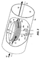
- the preferred ratio of the major axis 78 to the minor axis 68 of the elliptical profile is approximately five-to-one (shown in Figure 3 ).
- the partial sectioned perspective view of Figure 3 illustrates the aerodynamic noise abatement device 46 positioned inside the turbine exhaust duct 38.
- the noise abatement device 46 is fashioned about a single aerodynamic sparger 44a positioned within the turbine exhaust duct 38.
- the sparger 44a creates the final pressure drop required by the air-cooled condenser by dividing the flow of the incoming fluid into many small jets through a plurality of passageways about the periphery of the sparger 44a.
- the aerodynamic sparger 44a is preferably placed along the longitudinal axis 48 of the turbine exhaust duct 38 to utilize its minimized cross-sectional area to reduce the aerodynamic resistance within the turbine exhaust duct 38.
- the bypass steam 34 which has been mixed with spray water 33 at the desuperheater 24 ( Figure 1A ), enters the turbine exhaust duct 38 through the steam lines 41 a-b.
- the sparger 44a placed within the turbine exhaust duct 38 has an individual penetration. Flanges 47a-b are used to seal the turbine exhaust duct 38 at the penetration points of the aerodynamic noise abatement device 46.
- the aerodynamic sparger 44a is connected through conventional techniques using pipes 40 as illustrated in Figure 3 .
- the pressure of the reduced bypass steam 34 is typically in the range of 50 psi.
- a flow sector 95 of the aerodynamic sparger 144 is generally comprised of a stack of three elliptically shaped disks 96b-d having a substantially similar profile aligned with guide holes 97b-d.
- Each disk 96b-d integrates a plurality of inlet slots 92b-d, a plurality of outlet slots 94b-d, and a plurality of interconnecting plenums 99b-d within a single disk.
- the restrictive nature of the passageways accelerates the fluid as it moves through them.
- the plenums 99b-d create fluid chambers within the individual layers of the stacked disks and connect the inlet slots 92b-d to the outlet slots 94b-d allowing both axial and lateral flow within the disks 96b-d.
- the flow path geometry created within the sparger 144 produces staged pressure drops by subdividing the flow stream into smaller portions to reduce fluid pressure and further suppress noise generation by mixing the fluid within the fluid chambers.
- the total number of disks used in each sparger is dependent upon the fluid properties and the physical constraints of the application in which the sparger will be placed.
- the noise abatement device 46 has an inlet area to the outlet area ratio of approximately 6.5 to 1. Those skilled in the art recognize that deviations from the inlet area-to-outlet area ratio can be made without parting from the spirit and scope of the present noise abatement device.
- a solid top disk 96a and a mounting plate 96e form to the top surface and bottom surface of the sparger 144 to direct fluid flow through the sparger 144 and provide mounting arrangements within the turbine exhaust duct 38, respectively.
- the bottom plate 96e may include a port 98 that connects directly to the piping 41 a to receive conditioning steam 35 from the bypass circuit 19 (shown in Figure 1A ).
- the disks 96b-d, the top plate 96a, the bottom plate 96e and the piping 40 (Shown in Figure 4 ) may be attached by conventional means such as welding, but those skilled in the art recognize that alternate attachment means may be used.
- noise abatement device 46 is designed using alternating disks, other embodiments are conceivable.
- a tortuous flow path could be created using one or more disks where the tortuous flow paths connect the fluid inlet slots at the hollow center to the fluid outlet slots at the disk perimeter.
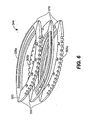
- FIG. 5 An illustrative perspective view of an alternate embodiment of a sparger provided with a single disk of the present noise abatement device using tortuous paths with a blocked sector is depicted in Figure 5 .
- the tortuous path sparger 244 is comprised of a plurality of disks 203 with an elliptical profile similar to those of the noise abatement device 46.
- fluid obstructers 220a-220f are positioned on the surface of each disk 203 to create tortuous passageways 204 that become progressively more restrictive.
- fluidic restrictions increase fluid velocity and consequently produce a corresponding decrease in fluid pressure at the outlet or on the downstream side of the restriction.
- a solid top plate 296a and a bottom mounting plate 296e are attached to the top surface and bottom surface of the sparger 244 to direct fluid flow through the sparger 244 and provide mounting arrangements for the noise abatement device.
- the bottom plate 296e further includes a port 298 that connects directly to piping (not shown) to receive conditioned steam 35 from the turbine bypass circuit 19 (shown in Figure 1A ).
- the disks 203, the top plate 296a, and the bottom plate 296e can be attached by conventional means such as welding, but those skilled in the art recognize that alternate attachment means may be used.
- the aerodynamic sparger can be constructed from a continuous hollow cylinder having an elliptical shape with direct radial fluid passageways.
- the noise abatement device 46 could be constructed using the alternating disks wherein alternating disks with individual flow disks and individual plenum disks are used to create the axial and lateral passageways.
- other manufacturing and assembly processes can be used to efficiently fabricate the disks within an aerodynamic sparger 344 shown in Figure 6 .
- individual flow sectors 300 and plenum sectors 310 can be produced using Electric Discharge Machining (EDM) methods and subsequently combined by conventional manufacturing techniques, such as a laser weld 320, to create each individual disk 305a-c.
- EDM Electric Discharge Machining
Landscapes
- Engineering & Computer Science (AREA)
- Chemical & Material Sciences (AREA)
- Chemical Kinetics & Catalysis (AREA)
- Mechanical Engineering (AREA)
- General Engineering & Computer Science (AREA)
- Combustion & Propulsion (AREA)
- Heat-Exchange Devices With Radiators And Conduit Assemblies (AREA)
- Engine Equipment That Uses Special Cycles (AREA)
- Turbine Rotor Nozzle Sealing (AREA)
- Supercharger (AREA)
- Soundproofing, Sound Blocking, And Sound Damping (AREA)
Abstract
Claims (9)
- Diffuseur adapté pour une mise en place dans une conduite, la conduite ayant un premier flux de fluide sensiblement parallèle à un axe longitudinal défini par la conduite, l'diffuseur comprenant :un boîtier ayant une forme elliptique définissant un bord avant (53a à 53c) et un bord arrière (54a à 54c) sensiblement similaires, le boîtier formant une chambre intérieure destinée à recevoir un second flux de fluide ayant une pression associée supérieure à celle du premier flux de fluide, la forme du boîtier fournissant une contre-pression sensiblement réduite lorsqu'il rencontre le premier flux de fluide ; etune pluralité de passages de fluide formés par le boîtier pour permettre au second flux de fluide de passer à travers la chambre afin de pénétrer le premier flux de fluide à une pression réduite.
- Diffuseur selon la revendication 1, dans lequel le boîtier est constitué d'une pluralité de disques empilés (96a à 96e) alignés autour d'un axe central des disques empilés.
- Diffuseur selon la revendication 2, dans lequel chaque disque est positionné de manière sélective dans la pile de disques afin de former les passages de fluide, chaque disque ayant(a) des fentes d'entrée de fluide (92b à 92d) s'étendant partiellement depuis un centre de disque creux vers une périphérie de disque,(b) des fentes de sortie de fluide (94b à 94d) s'étendant partiellement depuis la périphérie de disque vers le centre de disque, et(c) au moins une fente de répartition d'air (99b à 99d) s'étendant à travers le disque pour permettre un flux de fluide depuis les fentes d'entrée de fluide dans un disque vers les fentes de répartition d'air dans des disques adjacents et vers les fentes de sortie de fluide dans au moins un disque, dans lequel le trajet de flux de fluide est divisé en une pluralité de directions axiales le long de l'axe central, puis dans les fentes de répartition d'air avec une pluralité de directions de flux latérales, et ensuite réparti parmi de multiples fentes de sortie dans au moins un disque.
- Diffuseur selon la revendication 3, dans lequel la fente de répartition d'air dans le disque adjacent permet également de coupler un flux de fluide depuis les fentes d'entrée de fluide dans un disque à de multiples fentes de sortie de fluide dans des disques respectifs dans la pile adjacente au disque adjacent.
- Diffuseur selon la revendication 2, dans lequel chaque passage de fluide respectif est constitué d'un trajet de flux sinueux, chaque trajet de flux sinueux restant indépendant lors de la traversée du disque.
- Diffuseur selon la revendication 3, dans lequel les fentes d'entrée de fluide et les fentes de sortie de fluide sont formées dans un secteur de flux, et la fente de répartition d'air est formée dans un secteur de répartition d'air, le secteur de flux et le secteur de répartition d'air étant reliés pour former un disque individuel.
- Diffuseur selon la revendication 1, comprenant en outre :une pluralité de diffuseurs adaptés pour être mis en place dans la conduite.
- Diffuseur selon la revendication 7, dans lequel le boîtier de chaque diffuseur est constitué d'une pluralité de disques empilés alignés autour d'un axe central de la pluralité de disques empilés.
- Procédé de réduction de la résistance aérodynamique dans une gaine d'échappement de turbine ayant un premier flux de fluide, le procédé comprenant les étapes consistant à :façonner un diffuseur selon l'une quelconque des revendications 1 à 8 avec un boîtier ayant une chambre intérieure, le boîtier formant une pluralité de passages de fluide destinés à recevoir et à transférer un second flux de fluide à une pression supérieure dans le premier flux de fluide à un débit régulé, dans lequel le boîtier est mis en forme pour avoir un profil aérodynamique lorsqu'il rencontre le premier flux de fluide ; etmonter un dispositif de réduction du bruit constitué au moins dudit diffuseur dans une gaine d'échappement de turbine, le dispositif de réduction du bruit étant généralement situé de manière symétrique dans la conduite d'échappement de turbine.
Applications Claiming Priority (2)
| Application Number | Priority Date | Filing Date | Title |
|---|---|---|---|
| US10/647,799 US7185736B2 (en) | 2003-08-25 | 2003-08-25 | Aerodynamic noise abatement device and method for air-cooled condensing systems |
| PCT/US2004/023744 WO2005023405A1 (fr) | 2003-08-25 | 2004-07-23 | Dispositif aerodynamique de reduction de bruit et procede destine aux groupes compresseurs-condenseurs refroidis a l'air |
Publications (2)
| Publication Number | Publication Date |
|---|---|
| EP1673159A1 EP1673159A1 (fr) | 2006-06-28 |
| EP1673159B1 true EP1673159B1 (fr) | 2010-08-25 |
Family
ID=34216601
Family Applications (1)
| Application Number | Title | Priority Date | Filing Date |
|---|---|---|---|
| EP04779003A Expired - Lifetime EP1673159B1 (fr) | 2003-08-25 | 2004-07-23 | Canne d'injection et procede aerodynamique de reduction de bruit destine aux groupes compresseurs-condenseurs refroidis a l'air |
Country Status (11)
| Country | Link |
|---|---|
| US (1) | US7185736B2 (fr) |
| EP (1) | EP1673159B1 (fr) |
| AR (1) | AR046405A1 (fr) |
| AU (1) | AU2004270132B2 (fr) |
| BR (1) | BRPI0413137B1 (fr) |
| CA (1) | CA2532039C (fr) |
| MX (1) | MXPA06001912A (fr) |
| MY (1) | MY137936A (fr) |
| NO (1) | NO20060326L (fr) |
| RU (1) | RU2336423C2 (fr) |
| WO (1) | WO2005023405A1 (fr) |
Families Citing this family (17)
| Publication number | Priority date | Publication date | Assignee | Title |
|---|---|---|---|---|
| TWI242706B (en) * | 2004-03-08 | 2005-11-01 | Avance Technologies Inc | Convective cooling chassis air guide |
| US7044437B1 (en) * | 2004-11-12 | 2006-05-16 | Fisher Controls International Llc. | Flexible size sparger for air cooled condensors |
| EP1732062B1 (fr) * | 2005-06-07 | 2013-08-14 | Alstom Technology Ltd | Silencieux |
| DE102006017004B3 (de) * | 2006-04-11 | 2007-10-25 | Airbus Deutschland Gmbh | Vorrichtung zur Vermischung von Frischluft und Heizluft sowie Verwendung derselben in einem Belüftungssystem eines Flugzeuges |
| FR2945963A1 (fr) * | 2009-05-27 | 2010-12-03 | Mark Iv Systemes Moteurs Sa | Dispositif d'injection et de diffusion de fluide gazeux et repartition d'admission integrant un tel dispositif |
| DE102009029875A1 (de) * | 2009-06-22 | 2010-12-30 | Airbus Operations Gmbh | Strömungsbegrenzer und Verwendung eines Strömungsbegrenzers in einem Luftverteilungssystem eines Klimatisierungssystems eines Flugzeugs |
| EP2555977B1 (fr) * | 2010-04-09 | 2018-03-14 | Airbus Operations GmbH | Système de conditionnement d'air d'avion avec un dispositif de mélange |
| WO2014166507A1 (fr) * | 2013-04-08 | 2014-10-16 | Uglovsky Sergey Evgenievich | Refroidisseur et générateur à tourbillons de type à siphon thermique |
| WO2015175610A1 (fr) * | 2014-05-13 | 2015-11-19 | Holtec International | Système de conditionnement de vapeur |
| US9551280B1 (en) * | 2015-09-16 | 2017-01-24 | General Electric Company | Silencer panel and system having plastic perforated side wall |
| CN108458467B (zh) * | 2017-02-17 | 2020-11-10 | S.I.Pan公司 | 分离器以及包括该分离器的消声器 |
| US11043199B2 (en) * | 2018-04-25 | 2021-06-22 | Toyota Motor Engineering & Manufacturing North America, Inc. | Sparse acoustic absorber |
| AT521050B1 (de) * | 2018-05-29 | 2019-10-15 | Fachhochschule Burgenland Gmbh | Verfahren zur Steigerung der Energieeffizienz in Clausius-Rankine-Kreisprozessen |
| US11322126B2 (en) * | 2018-12-20 | 2022-05-03 | Toyota Motor Engineering & Manufacturing North America, Inc. | Broadband sparse acoustic absorber |
| US11353239B2 (en) * | 2019-08-28 | 2022-06-07 | Broan-Nutone Llc | Sound reduction grille assembly |
| US20220258108A1 (en) * | 2021-02-18 | 2022-08-18 | Moleaer, Inc | Nano-bubble generator |
| CN113680545B (zh) * | 2021-08-30 | 2022-12-16 | 浙江工业大学 | 一种采用旋转结构调节的降噪喷嘴 |
Family Cites Families (26)
| Publication number | Priority date | Publication date | Assignee | Title |
|---|---|---|---|---|
| US1473449A (en) * | 1920-06-28 | 1923-11-06 | Ralph O Stearns | Condenser for steam-driven machinery |
| US2916101A (en) * | 1957-02-25 | 1959-12-08 | Israel A Naman | Sound-absorbing structures |
| CH362093A (de) * | 1958-11-11 | 1962-05-31 | Escher Wyss Ag | Dampfturbine mit Bypass-Entspannungsvorrichtung |
| US3220710A (en) * | 1963-04-23 | 1965-11-30 | Ingersoll Rand Co | Self-regulating attemperator |
| US3217488A (en) * | 1964-04-22 | 1965-11-16 | Ohain Hans J P Von | Gas cooled colloid propulsion systems |
| DE1215731B (de) | 1964-09-29 | 1966-05-05 | Escher Wyss Gmbh | Dampfentspanner fuer Niederdruck-Umleiteinrichtungen in Dampfkraftanlagen |
| US3332442A (en) * | 1965-01-18 | 1967-07-25 | Zink Co John | Apparatus for mixing fluids |
| US3515499A (en) | 1968-04-22 | 1970-06-02 | Aerojet General Co | Blades and blade assemblies for turbine engines,compressors and the like |
| US3719524A (en) * | 1970-05-13 | 1973-03-06 | Gen Electric | Variable flow steam circulator |
| US4073832A (en) * | 1976-06-28 | 1978-02-14 | Texaco Inc. | Gas scrubber |
| US4041710A (en) * | 1976-09-09 | 1977-08-16 | Robert August Kraus | Hydraulic prime mover device |
| US4132077A (en) * | 1977-02-02 | 1979-01-02 | Johnson Don E | Process and apparatus for obtaining useful energy from a body of liquid at moderate temperature |
| US4221539A (en) * | 1977-04-20 | 1980-09-09 | The Garrett Corporation | Laminated airfoil and method for turbomachinery |
| US4315559A (en) * | 1977-12-09 | 1982-02-16 | Casey Russell A | Muffler for internal combustion engine |
| US4203706A (en) * | 1977-12-28 | 1980-05-20 | United Technologies Corporation | Radial wafer airfoil construction |
| US4314794A (en) * | 1979-10-25 | 1982-02-09 | Westinghouse Electric Corp. | Transpiration cooled blade for a gas turbine engine |
| US4392062A (en) * | 1980-12-18 | 1983-07-05 | Bervig Dale R | Fluid dynamic energy producing device |
| GB2254379B (en) * | 1981-04-28 | 1993-04-14 | Rolls Royce | Cooled aerofoil blade |
| US4705455A (en) * | 1985-12-23 | 1987-11-10 | United Technologies Corporation | Convergent-divergent film coolant passage |
| US5041246A (en) * | 1990-03-26 | 1991-08-20 | The Babcock & Wilcox Company | Two stage variable annulus spray attemperator method and apparatus |
| US5025831A (en) * | 1990-08-24 | 1991-06-25 | Exxon Research & Engineering Company | Compact radial flow distributor |
| US5458461A (en) * | 1994-12-12 | 1995-10-17 | General Electric Company | Film cooled slotted wall |
| US6026859A (en) * | 1998-01-28 | 2000-02-22 | Fisher Controls International, Inc. | Fluid pressure reduction device with linear flow characteristic |
| US6179997B1 (en) * | 1999-07-21 | 2001-01-30 | Phillips Petroleum Company | Atomizer system containing a perforated pipe sparger |
| US6739426B2 (en) * | 2002-05-31 | 2004-05-25 | Control Components, Inc. | Low-noise pressure reduction system |
| US7055324B2 (en) * | 2003-03-12 | 2006-06-06 | Fisher Controls International Llc | Noise abatement device and method for air-cooled condensing systems |
-
2003
- 2003-08-25 US US10/647,799 patent/US7185736B2/en not_active Expired - Lifetime
-
2004
- 2004-07-23 WO PCT/US2004/023744 patent/WO2005023405A1/fr active Application Filing
- 2004-07-23 CA CA2532039A patent/CA2532039C/fr not_active Expired - Fee Related
- 2004-07-23 RU RU2006109472/06A patent/RU2336423C2/ru not_active IP Right Cessation
- 2004-07-23 EP EP04779003A patent/EP1673159B1/fr not_active Expired - Lifetime
- 2004-07-23 BR BRPI0413137-1A patent/BRPI0413137B1/pt not_active IP Right Cessation
- 2004-07-23 MX MXPA06001912A patent/MXPA06001912A/es active IP Right Grant
- 2004-07-23 AU AU2004270132A patent/AU2004270132B2/en not_active Ceased
- 2004-08-02 MY MYPI20043116A patent/MY137936A/en unknown
- 2004-08-19 AR ARP040102978A patent/AR046405A1/es active IP Right Grant
-
2006
- 2006-01-20 NO NO20060326A patent/NO20060326L/no not_active Application Discontinuation
Also Published As
| Publication number | Publication date |
|---|---|
| MXPA06001912A (es) | 2006-05-31 |
| MY137936A (en) | 2009-04-30 |
| RU2336423C2 (ru) | 2008-10-20 |
| US20050045416A1 (en) | 2005-03-03 |
| CA2532039A1 (fr) | 2005-03-17 |
| US7185736B2 (en) | 2007-03-06 |
| NO20060326L (no) | 2006-03-22 |
| AR046405A1 (es) | 2005-12-07 |
| AU2004270132B2 (en) | 2010-06-17 |
| AU2004270132A1 (en) | 2005-03-17 |
| RU2006109472A (ru) | 2006-07-27 |
| BRPI0413137A (pt) | 2006-10-03 |
| CA2532039C (fr) | 2010-04-27 |
| EP1673159A1 (fr) | 2006-06-28 |
| WO2005023405A1 (fr) | 2005-03-17 |
| BRPI0413137B1 (pt) | 2013-03-19 |
Similar Documents
| Publication | Publication Date | Title |
|---|---|---|
| EP1673159B1 (fr) | Canne d'injection et procede aerodynamique de reduction de bruit destine aux groupes compresseurs-condenseurs refroidis a l'air | |
| EP1045114B1 (fr) | Turbine à gaz terrestre ayant un système de refroidissement et procédé de refroidissement | |
| US5791136A (en) | Combined-cycle power generation plant, including a gas turbine, an annual exhaust gas channel having swirl suppression vanes, and a heat recovery boiler | |
| JP5698895B2 (ja) | タービン用の排気フードを組立てるための方法及びシステム | |
| US7055324B2 (en) | Noise abatement device and method for air-cooled condensing systems | |
| JP4249903B2 (ja) | 蒸気タービン | |
| WO2012052740A1 (fr) | Dispositif d'étanchéité pour réduire la fuite de fluide dans une turbine | |
| CN204851442U (zh) | 用于涡轮机的排气扩散器、涡轮机和联合循环系统 | |
| JP5507338B2 (ja) | 蒸気タービン二流式低圧構成 | |
| CA2585895C (fr) | Tuyau perfore de taille flexible pour condenseurs refroidis a l'air | |
| CN112543842A (zh) | 蒸汽旁通引入部 | |
| US8857183B2 (en) | Steam turbine, power plant and method for operating steam turbine | |
| WO2015156804A1 (fr) | Système d'échappement de turbine à gaz | |
| RU2151341C1 (ru) | Деаэратор | |
| EP2338588B1 (fr) | Réduction du niveau de bruit d'ensembles formant aérateur | |
| RU2142581C1 (ru) | Способ работы струйной конденсационной установки паровой турбины (варианты) и струйная установка для его осуществления | |
| JP6239908B2 (ja) | タービンで使用されるための排気システム並びにその組立方法 | |
| JPS61215406A (ja) | 復水タ−ビン | |
| WO2000020798A1 (fr) | Procede de desaeration d'un liquide et dispositif de mise en oeuvre de ce procede |
Legal Events
| Date | Code | Title | Description |
|---|---|---|---|
| PUAI | Public reference made under article 153(3) epc to a published international application that has entered the european phase |
Free format text: ORIGINAL CODE: 0009012 |
|
| 17P | Request for examination filed |
Effective date: 20060322 |
|
| AK | Designated contracting states |
Kind code of ref document: A1 Designated state(s): FR GB |
|
| 17Q | First examination report despatched |
Effective date: 20060920 |
|
| DAX | Request for extension of the european patent (deleted) | ||
| RBV | Designated contracting states (corrected) |
Designated state(s): FR GB |
|
| RTI1 | Title (correction) |
Free format text: SPARGER AND AERODYNAMIC NOISE ABATEMENT METHOD FOR AIR-COOLED CONDENSING SYSTEMS |
|
| GRAP | Despatch of communication of intention to grant a patent |
Free format text: ORIGINAL CODE: EPIDOSNIGR1 |
|
| GRAS | Grant fee paid |
Free format text: ORIGINAL CODE: EPIDOSNIGR3 |
|
| GRAA | (expected) grant |
Free format text: ORIGINAL CODE: 0009210 |
|
| STAA | Information on the status of an ep patent application or granted ep patent |
Free format text: STATUS: THE PATENT HAS BEEN GRANTED |
|
| AK | Designated contracting states |
Kind code of ref document: B1 Designated state(s): FR GB |
|
| REG | Reference to a national code |
Ref country code: GB Ref legal event code: FG4D |
|
| PLBE | No opposition filed within time limit |
Free format text: ORIGINAL CODE: 0009261 |
|
| STAA | Information on the status of an ep patent application or granted ep patent |
Free format text: STATUS: NO OPPOSITION FILED WITHIN TIME LIMIT |
|
| 26N | No opposition filed |
Effective date: 20110526 |
|
| PGFP | Annual fee paid to national office [announced via postgrant information from national office to epo] |
Ref country code: GB Payment date: 20140729 Year of fee payment: 11 Ref country code: FR Payment date: 20140717 Year of fee payment: 11 |
|
| GBPC | Gb: european patent ceased through non-payment of renewal fee |
Effective date: 20150723 |
|
| PG25 | Lapsed in a contracting state [announced via postgrant information from national office to epo] |
Ref country code: GB Free format text: LAPSE BECAUSE OF NON-PAYMENT OF DUE FEES Effective date: 20150723 |
|
| REG | Reference to a national code |
Ref country code: FR Ref legal event code: ST Effective date: 20160331 |
|
| PG25 | Lapsed in a contracting state [announced via postgrant information from national office to epo] |
Ref country code: FR Free format text: LAPSE BECAUSE OF NON-PAYMENT OF DUE FEES Effective date: 20150731 |