EP1672308B1 - Dispositif d'allumage pour une charge explosive ou une composition pyrotechnique - Google Patents
Dispositif d'allumage pour une charge explosive ou une composition pyrotechnique Download PDFInfo
- Publication number
- EP1672308B1 EP1672308B1 EP05292460A EP05292460A EP1672308B1 EP 1672308 B1 EP1672308 B1 EP 1672308B1 EP 05292460 A EP05292460 A EP 05292460A EP 05292460 A EP05292460 A EP 05292460A EP 1672308 B1 EP1672308 B1 EP 1672308B1
- Authority
- EP
- European Patent Office
- Prior art keywords
- ignition
- initiation
- support
- ignition means
- fact
- Prior art date
- Legal status (The legal status is an assumption and is not a legal conclusion. Google has not performed a legal analysis and makes no representation as to the accuracy of the status listed.)
- Not-in-force
Links
Images


Classifications
-
- F—MECHANICAL ENGINEERING; LIGHTING; HEATING; WEAPONS; BLASTING
- F42—AMMUNITION; BLASTING
- F42C—AMMUNITION FUZES; ARMING OR SAFETY MEANS THEREFOR
- F42C19/00—Details of fuzes
- F42C19/08—Primers; Detonators
- F42C19/0838—Primers or igniters for the initiation or the explosive charge in a warhead
- F42C19/0842—Arrangements of a multiplicity of primers or detonators, dispersed within a warhead, for multiple mode selection
-
- F—MECHANICAL ENGINEERING; LIGHTING; HEATING; WEAPONS; BLASTING
- F42—AMMUNITION; BLASTING
- F42C—AMMUNITION FUZES; ARMING OR SAFETY MEANS THEREFOR
- F42C19/00—Details of fuzes
- F42C19/08—Primers; Detonators
- F42C19/095—Arrangements of a multiplicity of primers or detonators, dispersed around a warhead, one of the primers or detonators being selected for directional detonation effects
Definitions
- the technical field of the invention is that of devices for initiating an explosive charge or a pyrotechnic composition.
- Known devices are used in particular to initiate the explosive charges of military heads generating splinters or formed charge (generating a jet or a core). Similarly, in flash charges, it is sometimes necessary to initiate an angular sector to orient the spray. This angular sector being dependent on the desired focus.
- the initiation devices use at least one initiating component such as a detonator or an igniter.
- a detonator or an igniter are well known to those skilled in the art.
- these components include for example a hot wire, a resistive bridge or a semiconductor bridge (known under the name: SCB or "semi conductor bridge") which, when traversed by an electric current, communicates with the energy to an inflammatory or detonating pyrotechnic composition.
- the US Patent 5939663 thus describes a multi-function head whose initiation device comprises an axial detonator and a ring of peripheral detonators. All the detonators are connected to initiation means by separate wire connections. Depending on the detonators that are ordered, we obtain a coherent stream or a projection of splinters.
- the initiation device thus defined is complex and expensive to implement since it requires the mounting of the various detonators on a support which must be positioned precisely with respect to the load so that the desired effect is ensured.
- the DE-40011243 which forms a starting point for the preamble of claim 1, describes an initiation device for an explosive charge, this device comprises a selection circuit, two initiation means carried by a single insulating support and connected to a source energy.
- This patent does not disclose the structure of the initiation means nor the nature of the means providing the electrical connection between the initiation means and the selection circuit.
- the initiation device according to the invention is compact and inexpensive to manufacture. It is adaptable to different types of explosive charges and can reliably ensure the initiation of an explosive charge according to several modes of operation.
- the field of application of the invention is not limited to explosive multi-mode military heads.
- the device according to the invention can in fact also be used to initiate a pyrotechnic composition, for example a gas generating composition having several operating regimes (for example a gas generator comprising several selectively initiatable gas cartridges).
- the subject of the invention is an initiation device for an explosive charge or a pyrotechnic composition, which device comprises at least two initiation means carried by a single insulating support and connected to a power source, a device characterized in that that the single insulating support also carries the conductors connecting the initiation means to the energy source, the initiation means comprising pads carried by the surface of the support and connected by a semiconductor or resistive bridge, the conductors being made in the form of conductive tracks carried by a face of the support, the support comprising at least a first group of initiation means distributed over a peripheral ring and at least a second group of initiation means distributed over at least one diametric arm, all the initiator means comprising a first stud connected to a common conductor and the support also comprising at least two other control conductors which are each connected to second pads of two groups of separate initiation means.
- the initiation means comprise at least one semiconductor bridge.
- the initiation device may comprise initiation means distributed over a peripheral ring and on two orthogonal diametral arms.
- the device comprises at least a first control conductor ensuring the initiation of an axial initiation means.
- the device comprises at least one second control conductor ensuring the initiation of a first ring of initiation means distributed on the arms around the axial initiation means.
- the device comprises at least a third control conductor ensuring the initiation of a sector of means for initiating the peripheral ring.
- the peripheral ring comprises four sectors of initiation means each of which can be initiated separately by specific control conductors.
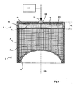
- a formed charge warhead 1 comprises an explosive charge 2 disposed in a cylindrical envelope 3.
- a concave coating 4 is applied against the explosive charge 2.
- the detonation characteristics of the explosive and the geometry of the coating 4 are chosen so that this warhead can have several different modes of operation depending on the initiation mode chosen. These characteristics are well known to those skilled in the art and will not be described here because they are not the subject of the present invention. For example, see EP1164348 which describes such a multi-function military head.
- the military head 1 can be initiated by an initiation device 5.
- the latter comprises a cylindrical housing 6 having substantially the same external diameter as the casing 3 of the military head 1 and closed by a bottom 6a plane on which is arranged a axial opening 7.
- the housing 6 encloses a single insulating support 8 which carries initiation means 9.
- a connector 10 is fixed at a rear face of the support 8 and it allows the connection of the initiation device 5 to an electronic control means 11 which incorporates a power source enabling activation of the initiation device 5.
- the connector 10 leaves the housing through the opening 7.
- the housing 6 also contains a detonating pyrotechnic composition 12, for example hexanitrostilbene (HNS) or compressed hexogen (RDX), which is applied by compression against the support 8.
- a detonating pyrotechnic composition 12 for example hexanitrostilbene (HNS) or compressed hexogen (RDX), which is applied by compression against the support 8.
- HNS hexanitrostilbene
- RDX compressed hexogen
- the housing 6 is fixed to the casing 3 by connecting means not shown here, for example by an outer ring screwed or crimped both on the casing 6 and on the casing 3 so that the military head 1 and the device Initiation 5 may for example form only one compound.
- a thin flap 13 for example made of aluminum, is applied to the face of the detonating composition 12 intended to come into contact with the explosive charge 2. This flap will perform a sealing function during storage of the initiation device 5 regardless of a military head 1.
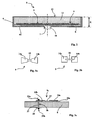
- the support 8 is visible more precisely at the figure 4 . It is made of an insulating material and carries initiation means 9 on one of its surfaces intended to come into contact with the detonating composition 12.
- FIG. 3a and 3b show in an enlarged manner two different embodiments of such an initiation means 9.
- figure 3a thus shows an initiation means 9 comprising a bridge 15 of semiconductor material which is disposed between two pads 14 of conductive material.
- the semiconductor bridge for example, made of doped silicon and copper pads.
- the pads have a width opposite the bridge which is less than their width away from the bridge. Such an arrangement makes it easier to initiate the initiation plasma between the pads.
- Such a semiconductor bridge is well known to those skilled in the art.
- EP0711400 which describes a semiconductor bridge initiator.
- the figure 3b shows another embodiment of an initiation means 9.
- the pads 14 are connected by a resistive conductive element 16 (for example gold).
- a resistive conductive element 16 for example gold
- this embodiment also well known to those skilled in the art
- it is the heating by Joule effect of the resistive element 16 (or explosion) that ensures the initiation of the detonating composition.
- the various initiation means 9 will be applied to the support 8 according to the integrated circuit manufacturing technology.
- a support carrying all the initiation means (with a particular geometrical distribution which will be specified later) and conductors (or tracks) will be realized according to this technique.
- conductive which ensure (via the connector 10) the connection of the initiation means 9 to a power source incorporated in the control means 11.
- the support 8 may thus be constituted by an amorphous silicon disk on which the initiation means and the conductive tracks will be made by metallization and / or vacuum deposition.
- the support 8 carries an axial initiation means 9a and a first group 17 of initiator means 9 distributed on a peripheral ring 18 (there are here twenty four initiators 9 regularly angularly distributed on the peripheral ring 18).
- the support 8 also comprises a second group of initiator means 9 distributed over at least one diametral arm.
- diametral arms 19a and 19b each comprising six initiating means 9. It will be noted that the ends of the diametral arms pass through initiating means 9b, 9c, 9d and 9e which belong to the peripheral ring 18.
- an upper surface of the support carries conductive tracks making it possible to connect the poles of certain initiators to the connector 10.
- all the initiating means comprise a first stud 14a which is connected to a common conductor C (all the pins connected to the common conductor are shown hatched on the figure 4 ).
- This common circuit passes through the pad 14a of the initiating means 9c and comprises a peripheral circular conductive track 20a and two other internal circular tracks 20b and 20c coaxial with the first.
- the common circuit also comprises a track 21 connecting the different circular tracks 20a, 20b and 20c of the common circuit.
- the upper face of the support 8 carries other conductive tracks making it possible to connect together.
- control conductors S2 b and S2 c which ensure the initiation of two other rings 23 and 24 of four initiating means distributed on the arms 19a and 19b and around the axial initiator means 9a.
- the poles 14b of these initiators are also all connected to each other by a portion of circular track, respectively 26 and 27.
- the device represented in figure 4 thus comprises on its peripheral ring 18 four sectors 28, 29, 30 and 31 which are delimited by the arms 19a and 19b. Each sector comprises five contiguous initiating means.
- Each of these sectors is controlled by a specific control conductor (S3 respectively a, S3 b, S3 c and S3 d).
- S3 specific control conductor
- the pads 14b of the initiators are all connected to each other by a portion of circular track. These track portions are in the figure the marks 32, 33, 34 and 35.
- the peripheral ring 18 there is on the peripheral ring 18 four insulated initiators 9b, 9c, 9d and 9e arranged at the ends of the arms 19a and 19b. Each of these initiators is controlled by a specific control conductor Si b , Si c , Si d and Si e .
- All the control conductors are connected to the connector 10 which thus comprises at least 13 pins.
- connections are made in the form of tracks carried by the other side of the support 8 and the connector is also carried by the other face and disposed at the center of the support.
- the double-sided circuit technology is well known to those skilled in the art.
- a bore 36 passes through the support 8. It allows to connect the two faces of the latter.
- This piercing, or hole metallized in the language of the skilled person, is filled by a metal deposit 37 which is connected by a weld 39a to the pad 14b and by a weld 39b to a conductive track 38 carried by the underside of the support 8 and which leads to the connector 10.
- the electronic control means 11 has not been described in detail because it does not constitute the object of the present invention.
- this control means is designed to send an electric firing current between the common conductor C and one or more of the control conductors S1, S2, S3 .... Si.
- the choice of drivers who will or will not be powered will be made using a means of programming and / or selection appropriate to the operational needs of the operating mode of the military head.
- the electronic control means sends a firing current to the only initiation means 9a, therefore between the common conductor C and the control conductor S1 ( figure 5a ).
- the figure 5b shows how it is possible to initiate such an operation.
- the electronic control means sends a current firing between the common conductor C and all S3 control lines a, S3 b, S3 c and S3 d and all insulated control conductors If b, Si c, If d and Si e . So all the means of initiation 9 of the crown external 18 are simultaneously initiated, both those in groups 28, 29, 30 and 31 that are isolated 9b, 9c, 9d and 9e.
- the initiation device described here comprises twelve groups of initiation means each of which can be actuated separately. It is therefore possible to obtain other modes of operation of the warhead.
- figure 5c shows an initiation mode in which all the initiating means distributed along the arms 19a and 19b are simultaneously controlled, as well as the isolated means 9b, 9c, 9d and 9e as those of the rings 22, 23 and 24.
- Such an initiation mode leads to the fragmentation of the coating and to the projection of these fragments according to the direction of action DA of the charge ( figure 1 ).
- the figure 5d shows an initiation mode in which all the initiation means of the sector 28 of the peripheral ring 18 are simultaneously controlled. Such an initiation mode leads to the projection of the fragments of the envelope 3 of the charge in a preferred direction DB substantially radial and opposite to the initiated sector.
- the device according to the invention makes it possible to obtain, in a simple manner, a means for ensuring the initiation of a multi-function military head.
- the technologies used are those that make it possible to achieve the individual initiation means. It is not more expensive to implement them to ensure also the realization of all the conductive tracks and thus obtain a complete component ensuring the desired effects.
- the support bearing its connector 10 is then placed in a simple manner inside its housing 6.
- the loading of the detonating composition 12 is performed according to the usual loading procedures for the initiators (or by gluing a sheet explosive plastic on the support).
- the positioning accuracy of the initiation means with respect to the casing of the military head 1 is finally obtained simply by a single operation of fixing the casing 6 on the casing 3.
- the axial size of the device according to the invention is reduced.
- the height E can thus be less than 5 mm, which allows the production of extremely compact military heads.
- initiation devices having a number of different initiation means or groups of initiation means.
- initiation means 9 are hot-wire or exploded initiators. After manufacture of the support 8 carrying the conductive tracks, it will then be necessary to solder son between the pads of each initiator. Such a mode is however less interesting because more expensive to achieve.
Abstract
Description
Le domaine technique de l'invention est celui des dispositifs permettant l'initiation d'une charge explosive ou d'une composition pyrotechnique.The technical field of the invention is that of devices for initiating an explosive charge or a pyrotechnic composition.
Les dispositifs connues sont mis en oeuvre notamment pour initier les charges explosives des têtes militaires génératrices d'éclats ou à charge formée (engendrant un jet ou un noyau). De même, dans les charges à éclats, il est parfois nécessaire d'amorcer un secteur angulaire afin d'orienter la gerbe. Ce secteur angulaire étant dépendant de la focalisation recherchée.Known devices are used in particular to initiate the explosive charges of military heads generating splinters or formed charge (generating a jet or a core). Similarly, in flash charges, it is sometimes necessary to initiate an angular sector to orient the spray. This angular sector being dependent on the desired focus.
Généralement les dispositifs d'initiation mettent en oeuvre au moins un composant d'initiation tel un détonateur ou un inflammateur. Ces composants sont bien connus de l'Homme du Métier. Suivant la technologie utilisée ils comprennent par exemple un fil chaud, un pont résistif ou un pont semi-conducteur (connu sous la dénomination : SCB ou "semi conductor bridge") qui, lorsqu'il est parcouru par un courant électrique, communique de l'énergie à une composition pyrotechnique inflammatrice ou détonante.Generally, the initiation devices use at least one initiating component such as a detonator or an igniter. These components are well known to those skilled in the art. Depending on the technology used they include for example a hot wire, a resistive bridge or a semiconductor bridge (known under the name: SCB or "semi conductor bridge") which, when traversed by an electric current, communicates with the energy to an inflammatory or detonating pyrotechnic composition.
Aujourd'hui, on cherche dans le domaine des têtes militaires à proposer des têtes multi-mode c'est à dire pouvant en fonction des besoins opérationnels engendrer des éclats, un jet de charge creuse ou un noyau formé par explosion.Today, we seek in the field of military heads to propose multi-mode heads that is to say that depending on operational requirements generate splinters, a hollow charge jet or a core formed by explosion.
Le
Le dispositif d'initiation ainsi défini est complexe et coûteux à mettre en oeuvre puisqu'il nécessite le montage des différents détonateurs sur un support qui doit être positionné de façon précise par rapport à la charge pour que l'effet recherché soit assuré.The initiation device thus defined is complex and expensive to implement since it requires the mounting of the various detonators on a support which must be positioned precisely with respect to the load so that the desired effect is ensured.
Il est également encombrant axialement et impose la réalisation d'une connectique filaire également encombrante.It is also bulky axially and requires the realization of a wired connection also bulky.
Le
Il n'est pas divulgué dans ce brevet la structure des moyens d'initiation ni la nature des moyens assurant la liaison électrique entre les moyens d'initiation et le circuit de sélection.This patent does not disclose the structure of the initiation means nor the nature of the means providing the electrical connection between the initiation means and the selection circuit.
C'est le but de l'invention que de proposer un dispositif d'initiation permettant de pallier de tels inconvénients.It is the object of the invention to provide an initiation device for overcoming such disadvantages.
Ainsi, le dispositif d'initiation selon l'invention est compact et peu coûteux à fabriquer. Il est adaptable à différents types de charges explosives et permet d'assurer d'une façon fiable l'initiation d'une charge explosive suivant plusieurs modes de fonctionnement.Thus, the initiation device according to the invention is compact and inexpensive to manufacture. It is adaptable to different types of explosive charges and can reliably ensure the initiation of an explosive charge according to several modes of operation.
Le domaine d'application de l'invention ne se limite pas aux têtes militaires explosives multi-modes. Le dispositif selon l'invention peut en effet être également utilisé pour initier une composition pyrotechnique par exemple une composition génératrice de gaz ayant plusieurs régimes de fonctionnement (par exemple un générateur de gaz comprenant plusieurs cartouches de gaz initiables sélectivement).The field of application of the invention is not limited to explosive multi-mode military heads. The device according to the invention can in fact also be used to initiate a pyrotechnic composition, for example a gas generating composition having several operating regimes (for example a gas generator comprising several selectively initiatable gas cartridges).
Ainsi, l'invention a pour objet un dispositif d'initiation pour une charge explosive ou une composition pyrotechnique, dispositif comprenant au moins deux moyens d'initiation portés par un support isolant unique et reliés à une source d'énergie, dispositif caractérisé en ce que le support isolant unique porte également les conducteurs assurant le raccordement des moyens d'initiation à la source d'énergie, les moyens d'initiation comprenant des plots portés par la surface du support et reliés par un pont semi-conducteur ou résistif, les conducteurs étant réalisés sous la forme de pistes conductrices portées par une face du support, le support comprenant au moins un premier groupe de moyens d'initiation répartis sur une couronne périphérique et au moins un deuxième groupe de moyens d'initiation répartis sur au moins un bras diamétral, tous les moyens initiateurs comprenant un premier plot relié à un conducteur commun et le support comprenant également au moins deux autres conducteurs de commande qui sont chacun reliés à des deuxièmes plots de deux groupes de moyens d'initiation distincts.Thus, the subject of the invention is an initiation device for an explosive charge or a pyrotechnic composition, which device comprises at least two initiation means carried by a single insulating support and connected to a power source, a device characterized in that that the single insulating support also carries the conductors connecting the initiation means to the energy source, the initiation means comprising pads carried by the surface of the support and connected by a semiconductor or resistive bridge, the conductors being made in the form of conductive tracks carried by a face of the support, the support comprising at least a first group of initiation means distributed over a peripheral ring and at least a second group of initiation means distributed over at least one diametric arm, all the initiator means comprising a first stud connected to a common conductor and the support also comprising at least two other control conductors which are each connected to second pads of two groups of separate initiation means.
Selon un mode particulier de réalisation, les moyens d'initiation comportent au moins un pont à semi-conducteur.According to a particular embodiment, the initiation means comprise at least one semiconductor bridge.
Le dispositif d'initiation selon l'invention pourra comprendre des moyens d'initiation répartis sur une couronne périphérique et sur deux bras diamétraux orthogonaux.The initiation device according to the invention may comprise initiation means distributed over a peripheral ring and on two orthogonal diametral arms.
Selon un autre mode particulier de réalisation, le dispositif comprend au moins un premier conducteur de commande assurant l'initiation d'un moyen d'initiation axial.According to another particular embodiment, the device comprises at least a first control conductor ensuring the initiation of an axial initiation means.
Selon un autre mode particulier de réalisation, le dispositif comprend au moins un deuxième conducteur de commande assurant l'initiation d'une première couronne de moyens d'initiation répartis sur les bras autour du moyen d'initiation axial.According to another particular embodiment, the device comprises at least one second control conductor ensuring the initiation of a first ring of initiation means distributed on the arms around the axial initiation means.
Selon un autre mode particulier de réalisation, le dispositif comprend au moins un troisième conducteur de commande assurant l'initiation d'un secteur de moyens d'initiation de la couronne périphérique.According to another particular embodiment, the device comprises at least a third control conductor ensuring the initiation of a sector of means for initiating the peripheral ring.
Selon un autre mode particulier de réalisation, la couronne périphérique comprend quatre secteurs de moyens d'initiation initiables chacun de façon distincte par des conducteurs de commande spécifiques.According to another particular embodiment, the peripheral ring comprises four sectors of initiation means each of which can be initiated separately by specific control conductors.
L'invention sera mieux comprise à la lecture de la description qui va suivre de différents modes de réalisation, description faite en référence aux dessins annexés et dans lesquels :
- la
figure 1 montre en coupe longitudinale une tête militaire multi-modes mettant en oeuvre un dispositif d'initiation selon l'invention, - la
figure 2 est une vue en coupe longitudinale d'un mode de réalisation du dispositif d'initiation seul, - la
figure 3a est une vue schématique d'un pont semi-conducteur élémentaire mis en oeuvre dans un mode de réalisation du dispositif d'initiation selon l'invention, - la
figure 3b est une vue schématique d'un pont résistif élémentaire mis en oeuvre dans un autre mode de réalisation du dispositif d'initiation selon l'invention, - la
figure 3c est une vue en coupe transversale partielle du support au niveau d'un moyen d'initiation, - la
figure 4 est une vue de dessus du support portant les différents moyens d'initiation élémentaires, - les
figures 5a, 5b ,5c et 5d sont des vues analogues à lafigure 4 mais schématisant les alimentations électriques utilisées pour assurer respectivement un fonctionnement : à amorçage central, à amorçage annulaire, à amorçage radial ou à amorçage par secteur.
- the
figure 1 shows in longitudinal section a multi-mode military head implementing an initiation device according to the invention, - the
figure 2 is a longitudinal sectional view of an embodiment of the initiation device alone, - the
figure 3a is a schematic view of an elementary semiconductor bridge implemented in one embodiment of the initiation device according to the invention, - the
figure 3b is a schematic view of an elementary resistive bridge implemented in another embodiment of the initiation device according to the invention, - the
figure 3c is a partial cross-sectional view of the support at an initiation means, - the
figure 4 is a view from above of the support carrying the various elementary initiation means, - the
Figures 5a, 5b ,5c and 5d are similar views to thefigure 4 but schematizing the power supplies used to respectively provide operation: centrally primed, ring primed, radial ignition or sector priming.
En se reportant à la
Les caractéristiques détoniques de l'explosif et la géométrie du revêtement 4 sont choisies de façon à ce que cette tête militaire puisse avoir plusieurs modes de fonctionnement différents en fonction du mode d'initiation choisi. Ces caractéristiques sont bien connues de l'Homme du Métier et ne seront donc pas décrites ici car elles ne font pas l'objet de la présente invention. On pourra à titre d'exemple se reporter au
La tête militaire 1 peut être initiée par un dispositif d'initiation 5. Ce dernier comprend un boîtier 6 cylindrique ayant sensiblement le même diamètre externe que l'enveloppe 3 de la tête militaire 1 et fermé par un fond 6a plan sur lequel est aménagée une ouverture axiale 7.The
Conformément à l'invention le boîtier 6 renferme un support isolant 8 unique qui porte des moyens d'initiation 9. Un connecteur 10 est fixé au niveau d'une face arrière du support 8 et il permet le raccordement du dispositif initiation 5 à un moyen de commande électronique 11 qui incorpore une source d'énergie permettant l'activation du dispositif d'initiation 5. Le connecteur 10 sort du boîtier par l'ouverture 7.According to the invention the
Le boîtier 6 renferme également une composition pyrotechnique détonante 12, par exemple de l'hexanitrostilbène (HNS) ou de l'hexogène (RDX) comprimé, qui est appliquée par compression contre le support 8. On pourrait également utiliser pour la composition 12 une feuille d'explosif plastique, par exemple d'un explosif à base de caoutchouc et de pentrite (explosif connu sous la marque Formex).The
Le boîtier 6 est fixé à l'enveloppe 3 par des moyens de liaison non représentés ici, par exemple par une bague externe vissée ou sertie à la fois sur le boîtier 6 et sur l'enveloppe 3 afin que la tête militaire 1 et le dispositif d'initiation 5 puissent par exemple ne former qu'un composé.The
Par ailleurs,comme cela est plus particulièrement visible à la
Le support 8 est visible plus précisément à la
Les
Les plots ont une largeur en regard du pont qui est inférieure à leur largeur à distance du pont. Une telle disposition permet de faciliter l'amorçage du plasma d'initiation entre les plots.The pads have a width opposite the bridge which is less than their width away from the bridge. Such an arrangement makes it easier to initiate the initiation plasma between the pads.
Un tel pont semi-conducteur est bien connu de l'Homme du Métier. On pourra par exemple se reporter au
Lorsqu'une tension électrique d'un certain niveau (qui dépend des caractéristiques dimensionnelles et physiques du matériau utilisé pour réaliser le pont 15) est appliquée entre les plots 14, un plasma est engendré au travers du pont 15 et l'énergie qui en résulte assure l'initiation de la composition détonante en contact avec le pont.When a voltage of a certain level (which depends on the dimensional and physical characteristics of the material used to make the bridge 15) is applied between the pads 14, a plasma is generated through the
La
Suivant un mode de réalisation préféré, les différents moyens d'initiation 9 seront appliqués sur le support 8 suivant la technologie de réalisation des circuits intégrés.According to a preferred embodiment, the various initiation means 9 will be applied to the
Il est en effet classique de réaliser suivant cette technique une pluralité de moyens d'initiation (à pont semi-conducteur ou résistif) sur un même support, les moyens étant ensuite découpés par exemple par laser pour être intégrés de façon individuelle chacun dans un boîtier distinct.It is indeed conventional to carry out according to this technique a plurality of initiation means (semiconductor bridge or resistive) on the same support, the means then being cut for example by laser to be individually integrated each into a housing separate.
Conformément à l'invention on réalisera suivant cette technique un support portant tous les moyens d'initiation (avec une répartition géométrique particulière qui sera précisée par la suite) ainsi que des conducteurs (ou pistes conductrices) qui assurent (via le connecteur 10) le raccordement des moyens d'initiation 9 à une source d'énergie incorporée au moyen de commande 11.In accordance with the invention, a support carrying all the initiation means (with a particular geometrical distribution which will be specified later) and conductors (or tracks) will be realized according to this technique. conductive) which ensure (via the connector 10) the connection of the initiation means 9 to a power source incorporated in the control means 11.
Le support 8 pourra ainsi être constitué par un disque de silicium amorphe sur lequel les moyens d'initiation ainsi que les pistes conductrices seront réalisés par métallisation et/ou dépôt sous vide.The
On voit sur la
Le support 8 comporte également un deuxième groupe de moyens initiateurs 9 répartis sur au moins un bras diamétral.The
Il y a ici deux bras diamétraux 19a et 19b comportant chacun six moyens initiateurs 9. On notera que les extrémités des bras diamétraux passent par des moyens initiateurs 9b, 9c, 9d et 9e qui appartiennent à la couronne périphérique 18.There are here two
Comme cela est visible sur la
Ainsi tous les moyens initiateurs comportent un premier plot 14a qui est relié à un conducteur commun C (tous les plots reliés au conducteur commun sont figurés hachurés sur la
Par ailleurs la face supérieure du support 8 porte d'autres pistes conductrices permettant de relier entre eux les deuxièmes plots 14b d'un certain nombre de moyens initiateurs distincts 9.Furthermore, the upper face of the
Il existe ainsi plusieurs groupes d'initiateurs 9 qui sont reliés entre eux et qui peuvent donc être initiés simultanément par le biais de conducteurs de commande spécifiques.There are thus several groups of
Il y a ainsi un premier conducteur de commande S1 assurant l'initiation d'un moyen initiateur axial 9a.There is thus a first control conductor S1 ensuring the initiation of an axial initiator means 9a.
Il y a également un deuxième conducteur de commande S2a qui assure l'initiation d'une première couronne 22 de quatre moyens initiateurs répartis sur les bras 19a et 19b et autour du moyen initiateur axial 9a. Les pôles 14b de ces initiateurs sont tous reliés les uns aux autres par une portion de piste circulaire 25.There is also a second control line S2 which ensures the initiation of a
D'une façon analogue il y a des conducteurs de commande S2b et S2c qui assurent l'initiation de deux autres couronnes 23 et 24 de quatre moyens initiateurs répartis sur les bras 19a et 19b et autour du moyen initiateur axial 9a. Les pôles 14b de ces initiateurs sont eux aussi tous reliés les uns aux autres par une portion de piste circulaire, respectivement 26 et 27.In a similar way there are control conductors S2 b and S2 c which ensure the initiation of two
Il y a enfin au moins un troisième conducteur de commande S3a qui assure l'initiation d'un secteur 28 de moyens initiateurs 9 tous situés sur la couronne périphérique 18.Finally, there is at least one third control conductor S3 a which initiates a
Le dispositif représenté à la
Chacun de ces secteurs est commandé par un conducteur de commande spécifique (respectivement S3a, S3b, S3c et S3d). Au niveau de chaque secteur, les plots 14b des initiateurs sont tous reliés les uns aux autres par une portion de piste circulaire. Ces portions de piste portent sur la figure les repères 32, 33, 34 et 35.Each of these sectors is controlled by a specific control conductor (S3 respectively a, S3 b, S3 c and S3 d). At each sector, the
Enfin comme cela a déjà été précisé précédemment, il y a sur la couronne périphérique 18 quatre initiateurs isolés 9b, 9c, 9d et 9e disposés aux extrémités des bras 19a et 19b. Chacun de ces initiateurs est commandé par un conducteur de commande spécifique Sib, Sic, Sid et Sie.Finally, as already mentioned above, there is on the
Tous les conducteurs de commande sont reliés au connecteur 10 qui comprend ainsi au moins 13 broches.All the control conductors are connected to the
Ces connexions sont représentées schématiquement sur la
Concrètement les connexions sont réalisées sous la forme de pistes portées par l'autre face du support 8 et le connecteur est également porté par l'autre face et disposé au niveau du centre du support.Concretely the connections are made in the form of tracks carried by the other side of the
La technologie des circuits double face est bien connue de l'Homme du Métier. A titre indicatif on a représenté sur la
Un perçage 36 traverse le support 8. Il permet de relier les deux faces de ce dernier. Ce perçage, ou trou métallisé dans le langage de l'Homme du Métier, est rempli par un dépôt métallique 37 qui est relié par une soudure 39a au plot 14b et par une soudure 39b à une piste conductrice 38 portée par la face inférieure du support 8 et qui conduit au connecteur 10.A bore 36 passes through the
L'Homme du Métier définira aisément la géométrie des pistes qui, réalisées au niveau de la face inférieure du support, permettront de relier les différents circuits de commande S au connecteur 10. Il suffira donc de réaliser, au niveau de chacun des groupes de moyens d'initiation portés par la face supérieure du support, un perçage traversant le support 8 au niveau d'un des plots 14b d'un des moyens d'initiation du groupe considéré. Par ailleurs un autre perçage réalisé au niveau du plot 14a du moyen d'initiation 9c assure le passage du conducteur commun C.Those skilled in the art will easily define the geometry of the tracks which, made at the level of the lower face of the support, will make it possible to connect the different control circuits S to the
Le moyen électronique de commande 11 n'a pas été décrit en détails car il ne constitue pas l'objet de la présente invention. D'une façon classique ce moyen de commande est conçu de façon à envoyer un courant électrique de mise à feu entre le conducteur commun C et un ou plusieurs des conducteurs de commande S1, S2, S3....Si. Le choix des conducteurs qui seront ou non alimentés sera fait à l'aide d'un moyen de programmation et/ou de sélection approprié aux besoins opérationnels de mode de fonctionnement de la tête militaire.The electronic control means 11 has not been described in detail because it does not constitute the object of the present invention. In a conventional manner this control means is designed to send an electric firing current between the common conductor C and one or more of the control conductors S1, S2, S3 .... Si. The choice of drivers who will or will not be powered will be made using a means of programming and / or selection appropriate to the operational needs of the operating mode of the military head.
Les différents modes de fonctionnement du dispositif selon l'invention vont être maintenant décrits en référence aux
Si on souhaite initier la tête militaire 1 de façon à ce qu'elle engendre un noyau il est nécessaire d'assurer un amorçage axial du chargement explosif 2.If it is desired to initiate the
Pour cela le moyen électronique de commande envoie un courant de mise à feu au seul moyen d'initiation 9a, donc entre le conducteur commun C et le conducteur de commande S1 (
Si on souhaite initier la tête militaire de façon à ce qu'elle engendre un jet de charge creuse, il est nécessaire de l'initier suivant une couronne circulaire. La
Le dispositif d'initiation qui est ici décrit comporte douze groupes de moyens d'initiation actionnables chacun de façon distincte. Il est donc possible d'obtenir d'autres modes de fonctionnement de la tête militaire.The initiation device described here comprises twelve groups of initiation means each of which can be actuated separately. It is therefore possible to obtain other modes of operation of the warhead.
A titre d'exemple la
Un tel mode d'initiation conduit à la fragmentation du revêtement et à la projection de ces fragments suivant la direction d'action DA de la charge (
La
On voit donc que le dispositif selon l'invention permet d'obtenir d'une façon simple un moyen permettant d'assurer l'initiation d'une tête militaire multi fonction.It can therefore be seen that the device according to the invention makes it possible to obtain, in a simple manner, a means for ensuring the initiation of a multi-function military head.
En effet, les technologies mises en oeuvre sont celles qui permettent de réaliser les moyens d'initiation individuels. Il n'est pas plus coûteux de les mettre en oeuvre pour assurer aussi la réalisation de toutes les pistes conductrices et obtenir ainsi un composant complet assurant les effets souhaités.Indeed, the technologies used are those that make it possible to achieve the individual initiation means. It is not more expensive to implement them to ensure also the realization of all the conductive tracks and thus obtain a complete component ensuring the desired effects.
Par ailleurs le positionnement des différents moyens d'initiation les uns par rapport aux autres est assuré d'une façon fiable et reproductible par la simple conception du dispositif.Furthermore, the positioning of the various initiation means relative to each other is ensured in a reliable and reproducible manner by the simple design of the device.
Le support portant son connecteur 10 est ensuite mis en place de façon simple à l'intérieur de son boîtier 6. Le chargement de la composition détonante 12 est effectué suivant les procédures de chargement habituelles pour les initiateurs (ou par le collage d'une feuille d'explosif plastique sur le support). La précision du positionnement des moyens d'initiation par rapport à l'enveloppe de la tête militaire 1 est enfin obtenue simplement par une opération unique de fixation du boîtier 6 sur l'enveloppe 3.The support bearing its
Par ailleurs l'encombrement axial du dispositif selon l'invention est réduit. La hauteur E peut ainsi être inférieure à 5 mm ce qui permet la réalisation de têtes militaires extrêmement compactes.Moreover, the axial size of the device according to the invention is reduced. The height E can thus be less than 5 mm, which allows the production of extremely compact military heads.
Diverses variantes sont possibles sans sortir du cadre de l'invention. Il est ainsi possible de réaliser des dispositifs d'initiation ayant un nombre de moyens d'initiation ou de groupes de moyens d'initiation différents.Various variants are possible without departing from the scope of the invention. It is thus possible to produce initiation devices having a number of different initiation means or groups of initiation means.
On pourra aussi définir des répartitions différentes pour les moyens d'initiation.It will also be possible to define different distributions for the initiation means.
Il est aussi possible de réaliser un dispositif selon l'invention dans lequel les moyens d'initiation 9 sont des initiateurs à fil chaud ou explosé. Après fabrication du support 8 portant les pistes conductrices, il sera alors nécessaire de souder des fils entre les plots de chaque initiateur. Un tel mode est cependant moins intéressant car plus coûteux à réaliser.It is also possible to produce a device according to the invention in which the initiation means 9 are hot-wire or exploded initiators. After manufacture of the
Il est aussi possible comme mentionné dans le préambule de réaliser avec l'invention un dispositif d'initiation pour des compositions génératrices de gaz.It is also possible as mentioned in the preamble to achieve with the invention an initiation device for gas generating compositions.
Claims (7)
- An ignition device (5) for an explosive charge or pyrotechnic composition, such device comprising at least two ignition means (9) carried by a single insulating support (8) and connected to a power source, such device characterized the support (8) carries also the conductors ensuring the connection of the ignition means (9) to the power source, the initiation means comprising studs (14) supported by the surface of the support (8) and connected by means of semiconductor (15) or resistive (16) bridge, the conductors being realised by conductive strips carried by a wall of the support (8), the support comprising at least a first group (17) of ignition means (9) spaced over a peripheral crown (18) and at least a second group of ignition means spaced over at least a diametral arm (19a, 19b), all the ignition means (9) comprising a first contact stud (14a) connected to a common conductor (C) and the support comprising also two other control conductors (S1, S2), which are each connected to second contact studs (14b) of two groups of separate ignition means (9).
- An ignition device according to Claim 1, characterized by the fact that the ignition means (9) incorporate at least one semiconductor bridge (15).
- An ignition device according to one of Claims 1 or 2, characterized by the fact that it comprises ignition means (9) spaced over a peripheral crown (18) and on two orthogonal diametral arms (19a, 19b).
- An ignition device according to one of Claims 1 to 3, characterized by the fact that it comprises at least a first control conductor (S1) ensuring the ignition of an axial ignition means (9a).
- An ignition device according to Claim 4, characterized by the fact that it comprises at least a second control conductor (S2a, S2b, S2c) ensuring the ignition of a first crown (22) of ignition means (9) spaced on arms around the axial ignition means (9a).
- An ignition device according to one of Claims 4 or 5, characterized by the fact that it comprises at least a third control conductor (S3a, S3b, S3c, S3d) ensuring the ignition of a sector (28, 29, 30, 31) of ignition means (9) of the peripheral crown (18).
- An ignition device according to Claim 6, characterized by the fact that the peripheral crown (18) comprises four sectors (28, 29, 30, 31) of ignition means (9), each able to be ignited separately by specific control conductors.
Applications Claiming Priority (1)
| Application Number | Priority Date | Filing Date | Title |
|---|---|---|---|
| FR0413471A FR2879732B1 (en) | 2004-12-16 | 2004-12-16 | INITIATION DEVICE FOR EXPLOSIVE LOAD OR PYROTECHNIC COMPOSITION |
Publications (2)
| Publication Number | Publication Date |
|---|---|
| EP1672308A1 EP1672308A1 (en) | 2006-06-21 |
| EP1672308B1 true EP1672308B1 (en) | 2010-07-28 |
Family
ID=34955394
Family Applications (1)
| Application Number | Title | Priority Date | Filing Date |
|---|---|---|---|
| EP05292460A Not-in-force EP1672308B1 (en) | 2004-12-16 | 2005-11-21 | Dispositif d'allumage pour une charge explosive ou une composition pyrotechnique |
Country Status (6)
| Country | Link |
|---|---|
| US (1) | US7434514B2 (en) |
| EP (1) | EP1672308B1 (en) |
| AT (1) | ATE475858T1 (en) |
| DE (1) | DE602005022533D1 (en) |
| ES (1) | ES2349934T3 (en) |
| FR (1) | FR2879732B1 (en) |
Families Citing this family (5)
| Publication number | Priority date | Publication date | Assignee | Title |
|---|---|---|---|---|
| US8414718B2 (en) * | 2004-01-14 | 2013-04-09 | Lockheed Martin Corporation | Energetic material composition |
| WO2008097241A2 (en) * | 2006-05-30 | 2008-08-14 | Lockheed Martin Corporation | Selectable effect warhead |
| US8250985B2 (en) | 2006-06-06 | 2012-08-28 | Lockheed Martin Corporation | Structural metallic binders for reactive fragmentation weapons |
| RU2502938C1 (en) * | 2012-08-01 | 2013-12-27 | Российская Федерация, от имени которой выступает Государственная корпорация по атомной энергии "Росатом"- Госкорпорация "Росатом" | Initiation system |
| RU2498200C1 (en) * | 2012-08-08 | 2013-11-10 | Федеральное бюджетное учреждение "12 Центральный научно-исследовательский институт Министерства обороны Российской Федерации" | Contact-sector charge of sheet explosive |
Family Cites Families (18)
| Publication number | Priority date | Publication date | Assignee | Title |
|---|---|---|---|---|
| US3877376A (en) * | 1960-07-27 | 1975-04-15 | Us Navy | Directed warhead |
| US3472165A (en) * | 1963-03-28 | 1969-10-14 | Us Air Force | Warhead |
| US5450794A (en) * | 1963-11-29 | 1995-09-19 | Drimmer; Bernard E. | Method for improving the performance of underwater explosive warheads |
| US5182418A (en) * | 1965-06-21 | 1993-01-26 | The United States Of America As Represented By The Secretary Of The Navy | Aimable warhead |
| US3443518A (en) * | 1967-09-26 | 1969-05-13 | Donald W Cross | Multi-point ignition system for shaped charges |
| US3703865A (en) * | 1968-02-28 | 1972-11-28 | Us Navy | Electronically controlled aimed blast warhead |
| US3598051A (en) * | 1968-07-25 | 1971-08-10 | Us Navy | Directional warhead |
| US3695178A (en) * | 1970-11-09 | 1972-10-03 | Robert E Betts | Delta squib circuit |
| US4026213A (en) * | 1971-06-17 | 1977-05-31 | The United States Of America As Represented By The Secretary Of The Navy | Selectively aimable warhead |
| US3995574A (en) * | 1974-07-29 | 1976-12-07 | Drimmer Bernard E | Dynamic method for enhancing effects of underwater explosions |
| DE3329969C1 (en) * | 1983-08-19 | 1990-06-13 | Fraunhofer Ges Forschung | Device for producing explosive-formed projectiles |
| US4862804A (en) * | 1985-05-22 | 1989-09-05 | Western Atlas International, Inc. | Implosion shaped charge perforator |
| DE4011243C1 (en) | 1990-04-06 | 1996-05-09 | Diehl Gmbh & Co | Warhead with shrapnel effect |
| FR2704052B1 (en) * | 1993-04-14 | 1995-05-24 | Thomson Brandt Armements | Multicore traceable charge. |
| FR2735567B1 (en) * | 1995-06-13 | 1997-07-25 | Tda Armements Sas | MILITARY HEAD, ESPECIALLY WITH A CORE GENERATOR |
| US5939663A (en) | 1996-02-14 | 1999-08-17 | The United States Of America As Represented By The Secretary Of The Army | Method for dispersing a jet from a shaped charge liner via multiple detonators |
| US6393991B1 (en) * | 2000-06-13 | 2002-05-28 | General Dynamics Ordnance And Tactical Systems, Inc. | K-charge—a multipurpose shaped charge warhead |
| US6598532B2 (en) * | 2001-08-14 | 2003-07-29 | Donald G. Gerard | Electric circuit for an electrically dischargeable primer |
-
2004
- 2004-12-16 FR FR0413471A patent/FR2879732B1/en not_active Expired - Fee Related
-
2005
- 2005-11-21 AT AT05292460T patent/ATE475858T1/en not_active IP Right Cessation
- 2005-11-21 DE DE602005022533T patent/DE602005022533D1/en active Active
- 2005-11-21 EP EP05292460A patent/EP1672308B1/en not_active Not-in-force
- 2005-11-21 ES ES05292460T patent/ES2349934T3/en active Active
- 2005-12-07 US US11/295,483 patent/US7434514B2/en not_active Expired - Fee Related
Also Published As
| Publication number | Publication date |
|---|---|
| US7434514B2 (en) | 2008-10-14 |
| FR2879732B1 (en) | 2010-03-19 |
| EP1672308A1 (en) | 2006-06-21 |
| US20080092764A1 (en) | 2008-04-24 |
| ATE475858T1 (en) | 2010-08-15 |
| FR2879732A1 (en) | 2006-06-23 |
| ES2349934T3 (en) | 2011-01-13 |
| DE602005022533D1 (en) | 2010-09-09 |
Similar Documents
| Publication | Publication Date | Title |
|---|---|---|
| EP1672308B1 (en) | Dispositif d'allumage pour une charge explosive ou une composition pyrotechnique | |
| EP0488863B1 (en) | Pyrotechnic detonator with coaxial connections | |
| EP0499500B1 (en) | Container provided with electrical connection means | |
| FR2772909A1 (en) | ELECTRO-PYROTECHNIC INITIATOR WITH THREE ELECTRICAL CONNECTIONS | |
| EP1594201B1 (en) | Multiple spark surface discharge spark plug | |
| EP1577635B1 (en) | Ignition system for two explosive charges and warhead which uses such an ignition system | |
| FR2796715A1 (en) | PYROTECHNIC INITIATOR AND METHOD FOR MOUNTING SUCH AN INITIATOR | |
| EP0076210B1 (en) | Electric bridge-wire initiator for pyrotechnic charges | |
| EP1584890B1 (en) | Warhead generating fragments | |
| FR2552871A1 (en) | Anti-tank projectile acting at the deviation speed | |
| FR2960055A1 (en) | GUIDED MUNITION PROTECTED BY AERODYNAMIC COIFFE | |
| EP0401114A1 (en) | Holding device for a projectile in relation to a telescoped ammunition case | |
| FR2560983A1 (en) | Electrical system for initiating pyrotechnic charges and ammunition or improved fuse incorporating such a system | |
| EP1524489B1 (en) | Ignition device and multi-mode shaped charge which uses such an ignition device | |
| EP2827091B1 (en) | Electrical initiator having two operating modes | |
| EP0648997B1 (en) | High energy fuse | |
| FR2646503A1 (en) | DEVICE FOR EJECTING CONTAINERS ON TRAJECTORY | |
| FR2866701A1 (en) | Multiple-core shaped charge, has elementary charges with their axes forming angle with axis of shaped charge or parallel to axis of shaped charge, where elementary charges are initiated by same initiation unit having single detonator | |
| EP2383539B1 (en) | Priming device with electric initiation for a projectile | |
| FR2660749A1 (en) | System for sequential, controlled and automatic triggering of a plurality of pyrotechnic payloads | |
| EP2383538A1 (en) | Priming device with initiation by influence for a projectile | |
| FR2897152A1 (en) | Firing system for fragmentation munition explosive charge has detonators positioned to create firing points along axis of munition | |
| WO2004083771A1 (en) | Metal cap for a pyrotechnic igniter | |
| CH506767A (en) | Fixed ammunition with consumable cartridge - case of propellant material | |
| FR2889301A1 (en) | Pyrotechnic initiator for munitions has two pins connected by electrical starter and linked to a photoelectric generator |
Legal Events
| Date | Code | Title | Description |
|---|---|---|---|
| PUAI | Public reference made under article 153(3) epc to a published international application that has entered the european phase |
Free format text: ORIGINAL CODE: 0009012 |
|
| AK | Designated contracting states |
Kind code of ref document: A1 Designated state(s): AT BE BG CH CY CZ DE DK EE ES FI FR GB GR HU IE IS IT LI LT LU LV MC NL PL PT RO SE SI SK TR |
|
| AX | Request for extension of the european patent |
Extension state: AL BA HR MK YU |
|
| 17P | Request for examination filed |
Effective date: 20061220 |
|
| AKX | Designation fees paid |
Designated state(s): AT BE BG CH CY CZ DE DK EE ES FI FR GB GR HU IE IS IT LI LT LU LV MC NL PL PT RO SE SI SK TR |
|
| RAP1 | Party data changed (applicant data changed or rights of an application transferred) |
Owner name: NEXTER MUNITIONS |
|
| 17Q | First examination report despatched |
Effective date: 20090716 |
|
| GRAP | Despatch of communication of intention to grant a patent |
Free format text: ORIGINAL CODE: EPIDOSNIGR1 |
|
| GRAS | Grant fee paid |
Free format text: ORIGINAL CODE: EPIDOSNIGR3 |
|
| GRAA | (expected) grant |
Free format text: ORIGINAL CODE: 0009210 |
|
| AK | Designated contracting states |
Kind code of ref document: B1 Designated state(s): AT BE BG CH CY CZ DE DK EE ES FI FR GB GR HU IE IS IT LI LT LU LV MC NL PL PT RO SE SI SK TR |
|
| REG | Reference to a national code |
Ref country code: GB Ref legal event code: FG4D Free format text: NOT ENGLISH |
|
| REG | Reference to a national code |
Ref country code: CH Ref legal event code: EP |
|
| REG | Reference to a national code |
Ref country code: IE Ref legal event code: FG4D Free format text: LANGUAGE OF EP DOCUMENT: FRENCH |
|
| REF | Corresponds to: |
Ref document number: 602005022533 Country of ref document: DE Date of ref document: 20100909 Kind code of ref document: P |
|
| REG | Reference to a national code |
Ref country code: SE Ref legal event code: TRGR |
|
| REG | Reference to a national code |
Ref country code: NL Ref legal event code: VDEP Effective date: 20100728 |
|
| LTIE | Lt: invalidation of european patent or patent extension |
Effective date: 20100728 |
|
| REG | Reference to a national code |
Ref country code: ES Ref legal event code: FG2A Effective date: 20101230 |
|
| PG25 | Lapsed in a contracting state [announced via postgrant information from national office to epo] |
Ref country code: FI Free format text: LAPSE BECAUSE OF FAILURE TO SUBMIT A TRANSLATION OF THE DESCRIPTION OR TO PAY THE FEE WITHIN THE PRESCRIBED TIME-LIMIT Effective date: 20100728 Ref country code: NL Free format text: LAPSE BECAUSE OF FAILURE TO SUBMIT A TRANSLATION OF THE DESCRIPTION OR TO PAY THE FEE WITHIN THE PRESCRIBED TIME-LIMIT Effective date: 20100728 Ref country code: AT Free format text: LAPSE BECAUSE OF FAILURE TO SUBMIT A TRANSLATION OF THE DESCRIPTION OR TO PAY THE FEE WITHIN THE PRESCRIBED TIME-LIMIT Effective date: 20100728 Ref country code: LT Free format text: LAPSE BECAUSE OF FAILURE TO SUBMIT A TRANSLATION OF THE DESCRIPTION OR TO PAY THE FEE WITHIN THE PRESCRIBED TIME-LIMIT Effective date: 20100728 |
|
| PG25 | Lapsed in a contracting state [announced via postgrant information from national office to epo] |
Ref country code: CY Free format text: LAPSE BECAUSE OF FAILURE TO SUBMIT A TRANSLATION OF THE DESCRIPTION OR TO PAY THE FEE WITHIN THE PRESCRIBED TIME-LIMIT Effective date: 20100728 Ref country code: SI Free format text: LAPSE BECAUSE OF FAILURE TO SUBMIT A TRANSLATION OF THE DESCRIPTION OR TO PAY THE FEE WITHIN THE PRESCRIBED TIME-LIMIT Effective date: 20100728 Ref country code: PT Free format text: LAPSE BECAUSE OF FAILURE TO SUBMIT A TRANSLATION OF THE DESCRIPTION OR TO PAY THE FEE WITHIN THE PRESCRIBED TIME-LIMIT Effective date: 20101129 Ref country code: PL Free format text: LAPSE BECAUSE OF FAILURE TO SUBMIT A TRANSLATION OF THE DESCRIPTION OR TO PAY THE FEE WITHIN THE PRESCRIBED TIME-LIMIT Effective date: 20100728 Ref country code: IS Free format text: LAPSE BECAUSE OF FAILURE TO SUBMIT A TRANSLATION OF THE DESCRIPTION OR TO PAY THE FEE WITHIN THE PRESCRIBED TIME-LIMIT Effective date: 20101128 Ref country code: BG Free format text: LAPSE BECAUSE OF FAILURE TO SUBMIT A TRANSLATION OF THE DESCRIPTION OR TO PAY THE FEE WITHIN THE PRESCRIBED TIME-LIMIT Effective date: 20101028 |
|
| REG | Reference to a national code |
Ref country code: IE Ref legal event code: FD4D |
|
| PG25 | Lapsed in a contracting state [announced via postgrant information from national office to epo] |
Ref country code: GR Free format text: LAPSE BECAUSE OF FAILURE TO SUBMIT A TRANSLATION OF THE DESCRIPTION OR TO PAY THE FEE WITHIN THE PRESCRIBED TIME-LIMIT Effective date: 20101029 Ref country code: LV Free format text: LAPSE BECAUSE OF FAILURE TO SUBMIT A TRANSLATION OF THE DESCRIPTION OR TO PAY THE FEE WITHIN THE PRESCRIBED TIME-LIMIT Effective date: 20100728 |
|
| PG25 | Lapsed in a contracting state [announced via postgrant information from national office to epo] |
Ref country code: DK Free format text: LAPSE BECAUSE OF FAILURE TO SUBMIT A TRANSLATION OF THE DESCRIPTION OR TO PAY THE FEE WITHIN THE PRESCRIBED TIME-LIMIT Effective date: 20100728 Ref country code: IE Free format text: LAPSE BECAUSE OF FAILURE TO SUBMIT A TRANSLATION OF THE DESCRIPTION OR TO PAY THE FEE WITHIN THE PRESCRIBED TIME-LIMIT Effective date: 20100728 |
|
| BERE | Be: lapsed |
Owner name: NEXTER MUNITIONS Effective date: 20101130 |
|
| PG25 | Lapsed in a contracting state [announced via postgrant information from national office to epo] |
Ref country code: SK Free format text: LAPSE BECAUSE OF FAILURE TO SUBMIT A TRANSLATION OF THE DESCRIPTION OR TO PAY THE FEE WITHIN THE PRESCRIBED TIME-LIMIT Effective date: 20100728 Ref country code: RO Free format text: LAPSE BECAUSE OF FAILURE TO SUBMIT A TRANSLATION OF THE DESCRIPTION OR TO PAY THE FEE WITHIN THE PRESCRIBED TIME-LIMIT Effective date: 20100728 Ref country code: CZ Free format text: LAPSE BECAUSE OF FAILURE TO SUBMIT A TRANSLATION OF THE DESCRIPTION OR TO PAY THE FEE WITHIN THE PRESCRIBED TIME-LIMIT Effective date: 20100728 Ref country code: EE Free format text: LAPSE BECAUSE OF FAILURE TO SUBMIT A TRANSLATION OF THE DESCRIPTION OR TO PAY THE FEE WITHIN THE PRESCRIBED TIME-LIMIT Effective date: 20100728 |
|
| PLBE | No opposition filed within time limit |
Free format text: ORIGINAL CODE: 0009261 |
|
| STAA | Information on the status of an ep patent application or granted ep patent |
Free format text: STATUS: NO OPPOSITION FILED WITHIN TIME LIMIT |
|
| PG25 | Lapsed in a contracting state [announced via postgrant information from national office to epo] |
Ref country code: MC Free format text: LAPSE BECAUSE OF NON-PAYMENT OF DUE FEES Effective date: 20101130 |
|
| REG | Reference to a national code |
Ref country code: CH Ref legal event code: PL |
|
| 26N | No opposition filed |
Effective date: 20110429 |
|
| PG25 | Lapsed in a contracting state [announced via postgrant information from national office to epo] |
Ref country code: LI Free format text: LAPSE BECAUSE OF NON-PAYMENT OF DUE FEES Effective date: 20101130 Ref country code: CH Free format text: LAPSE BECAUSE OF NON-PAYMENT OF DUE FEES Effective date: 20101130 |
|
| REG | Reference to a national code |
Ref country code: DE Ref legal event code: R097 Ref document number: 602005022533 Country of ref document: DE Effective date: 20110429 |
|
| PG25 | Lapsed in a contracting state [announced via postgrant information from national office to epo] |
Ref country code: BE Free format text: LAPSE BECAUSE OF NON-PAYMENT OF DUE FEES Effective date: 20101130 |
|
| PG25 | Lapsed in a contracting state [announced via postgrant information from national office to epo] |
Ref country code: HU Free format text: LAPSE BECAUSE OF FAILURE TO SUBMIT A TRANSLATION OF THE DESCRIPTION OR TO PAY THE FEE WITHIN THE PRESCRIBED TIME-LIMIT Effective date: 20110129 Ref country code: LU Free format text: LAPSE BECAUSE OF NON-PAYMENT OF DUE FEES Effective date: 20101121 |
|
| PG25 | Lapsed in a contracting state [announced via postgrant information from national office to epo] |
Ref country code: TR Free format text: LAPSE BECAUSE OF FAILURE TO SUBMIT A TRANSLATION OF THE DESCRIPTION OR TO PAY THE FEE WITHIN THE PRESCRIBED TIME-LIMIT Effective date: 20100728 |
|
| PGFP | Annual fee paid to national office [announced via postgrant information from national office to epo] |
Ref country code: GB Payment date: 20141024 Year of fee payment: 10 Ref country code: SE Payment date: 20141024 Year of fee payment: 10 Ref country code: ES Payment date: 20141103 Year of fee payment: 10 Ref country code: DE Payment date: 20141023 Year of fee payment: 10 |
|
| PGFP | Annual fee paid to national office [announced via postgrant information from national office to epo] |
Ref country code: IT Payment date: 20141027 Year of fee payment: 10 |
|
| REG | Reference to a national code |
Ref country code: FR Ref legal event code: PLFP Year of fee payment: 11 |
|
| REG | Reference to a national code |
Ref country code: DE Ref legal event code: R119 Ref document number: 602005022533 Country of ref document: DE |
|
| GBPC | Gb: european patent ceased through non-payment of renewal fee |
Effective date: 20151121 |
|
| PG25 | Lapsed in a contracting state [announced via postgrant information from national office to epo] |
Ref country code: IT Free format text: LAPSE BECAUSE OF NON-PAYMENT OF DUE FEES Effective date: 20151121 |
|
| PG25 | Lapsed in a contracting state [announced via postgrant information from national office to epo] |
Ref country code: SE Free format text: LAPSE BECAUSE OF NON-PAYMENT OF DUE FEES Effective date: 20151122 |
|
| REG | Reference to a national code |
Ref country code: FR Ref legal event code: PLFP Year of fee payment: 12 |
|
| PG25 | Lapsed in a contracting state [announced via postgrant information from national office to epo] |
Ref country code: GB Free format text: LAPSE BECAUSE OF NON-PAYMENT OF DUE FEES Effective date: 20151121 Ref country code: DE Free format text: LAPSE BECAUSE OF NON-PAYMENT OF DUE FEES Effective date: 20160601 |
|
| REG | Reference to a national code |
Ref country code: ES Ref legal event code: FD2A Effective date: 20161228 |
|
| PG25 | Lapsed in a contracting state [announced via postgrant information from national office to epo] |
Ref country code: ES Free format text: LAPSE BECAUSE OF NON-PAYMENT OF DUE FEES Effective date: 20151122 |
|
| REG | Reference to a national code |
Ref country code: FR Ref legal event code: PLFP Year of fee payment: 13 |
|
| PGFP | Annual fee paid to national office [announced via postgrant information from national office to epo] |
Ref country code: FR Payment date: 20171020 Year of fee payment: 13 |
|
| PG25 | Lapsed in a contracting state [announced via postgrant information from national office to epo] |
Ref country code: FR Free format text: LAPSE BECAUSE OF NON-PAYMENT OF DUE FEES Effective date: 20181130 |