EP1672242B1 - Aggregatelager - Google Patents
Aggregatelager Download PDFInfo
- Publication number
- EP1672242B1 EP1672242B1 EP05023521A EP05023521A EP1672242B1 EP 1672242 B1 EP1672242 B1 EP 1672242B1 EP 05023521 A EP05023521 A EP 05023521A EP 05023521 A EP05023521 A EP 05023521A EP 1672242 B1 EP1672242 B1 EP 1672242B1
- Authority
- EP
- European Patent Office
- Prior art keywords
- support
- spring body
- assembly mounting
- mounting according
- bracket
- Prior art date
- Legal status (The legal status is an assumption and is not a legal conclusion. Google has not performed a legal analysis and makes no representation as to the accuracy of the status listed.)
- Not-in-force
Links
Images


Classifications
-
- F—MECHANICAL ENGINEERING; LIGHTING; HEATING; WEAPONS; BLASTING
- F16—ENGINEERING ELEMENTS AND UNITS; GENERAL MEASURES FOR PRODUCING AND MAINTAINING EFFECTIVE FUNCTIONING OF MACHINES OR INSTALLATIONS; THERMAL INSULATION IN GENERAL
- F16F—SPRINGS; SHOCK-ABSORBERS; MEANS FOR DAMPING VIBRATION
- F16F1/00—Springs
- F16F1/36—Springs made of rubber or other material having high internal friction, e.g. thermoplastic elastomers
- F16F1/38—Springs made of rubber or other material having high internal friction, e.g. thermoplastic elastomers with a sleeve of elastic material between a rigid outer sleeve and a rigid inner sleeve or pin, i.e. bushing-type
- F16F1/3842—Method of assembly, production or treatment; Mounting thereof
- F16F1/3849—Mounting brackets therefor, e.g. stamped steel brackets; Restraining links
-
- F—MECHANICAL ENGINEERING; LIGHTING; HEATING; WEAPONS; BLASTING
- F16—ENGINEERING ELEMENTS AND UNITS; GENERAL MEASURES FOR PRODUCING AND MAINTAINING EFFECTIVE FUNCTIONING OF MACHINES OR INSTALLATIONS; THERMAL INSULATION IN GENERAL
- F16F—SPRINGS; SHOCK-ABSORBERS; MEANS FOR DAMPING VIBRATION
- F16F13/00—Units comprising springs of the non-fluid type as well as vibration-dampers, shock-absorbers, or fluid springs
- F16F13/04—Units comprising springs of the non-fluid type as well as vibration-dampers, shock-absorbers, or fluid springs comprising both a plastics spring and a damper, e.g. a friction damper
- F16F13/06—Units comprising springs of the non-fluid type as well as vibration-dampers, shock-absorbers, or fluid springs comprising both a plastics spring and a damper, e.g. a friction damper the damper being a fluid damper, e.g. the plastics spring not forming a part of the wall of the fluid chamber of the damper
- F16F13/08—Units comprising springs of the non-fluid type as well as vibration-dampers, shock-absorbers, or fluid springs comprising both a plastics spring and a damper, e.g. a friction damper the damper being a fluid damper, e.g. the plastics spring not forming a part of the wall of the fluid chamber of the damper the plastics spring forming at least a part of the wall of the fluid chamber of the damper
- F16F13/10—Units comprising springs of the non-fluid type as well as vibration-dampers, shock-absorbers, or fluid springs comprising both a plastics spring and a damper, e.g. a friction damper the damper being a fluid damper, e.g. the plastics spring not forming a part of the wall of the fluid chamber of the damper the plastics spring forming at least a part of the wall of the fluid chamber of the damper the wall being at least in part formed by a flexible membrane or the like
-
- F—MECHANICAL ENGINEERING; LIGHTING; HEATING; WEAPONS; BLASTING
- F16—ENGINEERING ELEMENTS AND UNITS; GENERAL MEASURES FOR PRODUCING AND MAINTAINING EFFECTIVE FUNCTIONING OF MACHINES OR INSTALLATIONS; THERMAL INSULATION IN GENERAL
- F16F—SPRINGS; SHOCK-ABSORBERS; MEANS FOR DAMPING VIBRATION
- F16F13/00—Units comprising springs of the non-fluid type as well as vibration-dampers, shock-absorbers, or fluid springs
- F16F13/04—Units comprising springs of the non-fluid type as well as vibration-dampers, shock-absorbers, or fluid springs comprising both a plastics spring and a damper, e.g. a friction damper
- F16F13/06—Units comprising springs of the non-fluid type as well as vibration-dampers, shock-absorbers, or fluid springs comprising both a plastics spring and a damper, e.g. a friction damper the damper being a fluid damper, e.g. the plastics spring not forming a part of the wall of the fluid chamber of the damper
- F16F13/08—Units comprising springs of the non-fluid type as well as vibration-dampers, shock-absorbers, or fluid springs comprising both a plastics spring and a damper, e.g. a friction damper the damper being a fluid damper, e.g. the plastics spring not forming a part of the wall of the fluid chamber of the damper the plastics spring forming at least a part of the wall of the fluid chamber of the damper
- F16F13/14—Units of the bushing type, i.e. loaded predominantly radially
- F16F13/1409—Units of the bushing type, i.e. loaded predominantly radially characterised by buffering features or stoppers
Definitions
- the invention relates to assembly bearing with a support and a support bearing, which are connected by a spring body made of elastomeric material, wherein the support has a bracket which surrounds the support bearing and the spring body, viewed in cross-section U-shaped.
- Such an assembly bearing is from the DE 100 24 535 A1 known.
- the known assembly bearing has a support and a spring body made of an elastic material which define a working chamber and a compensation chamber.
- the working chamber and the compensation chamber are separated from each other by a partition, filled with damping fluid and fluidly connected to each other by a damping channel.
- the spring body is enclosed by a cross-sectionally U-shaped bracket, wherein the bracket is mounted on the support. The bracket limits the spring travel in vehicle X and Z direction and increases the rigidity of the assembly bearing.
- the invention has for its object to further develop the previously known assembly bearing so that it is inexpensive and easy to manufacture and that it is suitable to absorb high forces.
- the support with the bracket can be manufactured as a complete component, for example by die-casting. Due to the high rigidity of the bracket, the assembly bearing is very well suited for use in a front-wheel drive vehicle, since the support has a high rigidity by the bracket and acting forces can be supported by the high drive torque or in a possible accident through the housing.
- the required in a two-part design separate stable connection between two components deleted.
- the working chamber may be hydraulically connected in addition to the damping channel with a Tilgerkanal. When the frequency range of the hydraulic damping is exceeded, the liquid column remains by its inertia in the long damping channel. The displaced by compression of the bearing
- Liquid volume can then be absorbed only by the swelling capacity of the support body and therefore leads to high dynamic hardening of the bearing.
- the shorter absorber channel reduces the dynamic spring rate of the assembly bearing in the tuned frequency range.
- the cross section and the length of the absorber channel can be changed electronically or pneumatically.
- the absorber channel is, as well as the damping channel, arranged without the use of additional components and thus additional manufacturing steps in the support. An additional absorber channel therefore causes little additional cost.
- the support bearing may be formed as a core.
- a trained as a core support bearing can be safely and easily embedded in the elastomeric spring body.
- the core can, viewed in cross section, be enclosed by the elastomeric material of the spring body. This protects the core against damage. In particular, a direct contact between the metallic core and the metallic bracket is avoided, which can lead to noise and premature damage to both parts.
- the bracket may be provided on the support bearing and the spring body side facing with a coating of elastomeric material.
- the additional coating determines with the stop contour the Progressionsverlauf the attacks.
- the additional coating further ensures that the metallic core, when not enclosed by the spring body, will strike the metal yoke, resulting in noise and premature wear.
- the coating and the spring body can be formed in one piece and of uniform material.
- the coating and the spring body can be made in the same operation and fixed in the support. As a result, the number of parts and the number of manufacturing steps are further reduced and thereby the manufacturing costs are lowered.
- the support bearing and / or the spring body can be viewed on the top with a cable stop and viewed in cross section, laterally with transverse stops.
- the assembly bearing can support the high forces of the drive torque.
- This support function requires the support bearing and / or the spring body large-volume attacks, which derive the forces occurring on the support.
- These stops of elastomeric material can be mounted either on the support bearing or on the spring body.
- the bracket may have reinforcement ribs on the outside facing away from the support body and the spring body.
- the reinforcing ribs increase the stiffness of the bracket and thus of the entire assembly bearing.
- the support and the spring body define a working chamber and a compensation chamber, both of which are filled with damping fluid.
- the working chamber and the compensation chamber are separated from one another by a dividing wall and connected to one another in a flow-conducting manner by a damping channel. Hydraulic assembly bearings are used if the requirements for vibration damping are greater. They are used in particular for damping engine vibrations in motor vehicles.
- the viewed in plan view, radially outwardly directed wall of the absorber channel is at least partially formed of an elastomeric material.
- the elastomeric wall in combination with the absorber channel length and cross section determines the frequency position of the absorber.
- the elastomers Wall can be made in one piece and with the same material together with the spring body and the elastomeric coating of the support. This reduces the number of manufacturing steps and the number of components.
- the partition may be formed as a nozzle cage comprising two nozzle disks and a membrane arranged between the nozzle disks.
- the nozzle cage with membrane serves for the acoustic decoupling of high-frequency vibrations with small amplitudes. To exclude adverse influence, it may be advantageous to provide only the absorber channel or the above-mentioned acoustic decoupling.
- the compensation chamber can be limited on the working chamber axially facing away from the side by a rolling bellows and the rolling bellows can be attached in a liquid-tight manner to the support with one piece and material uniformly connected to the support claws. If a threat to the bellows is excluded can be waived with appropriate design of the Rollbalgeinschreib on the final cover and thus another component can be saved. Since the claws are attached in one piece and the same material on the support bearing, no additional components are required for liquid-tight attachment of the rolling bellows.
Description
- Die Erfindung betrifft Aggregatelager mit einem Auflager und einem Traglager, die durch einen Federkörper aus elastomerem Werkstoff verbunden sind, wobei das Auflager einen Bügel aufweist, der das Traglager und den Federkörper, im Querschnitt betrachtet U-förmig umschließt.
- Ein derartiges Aggregatelager ist aus der
DE 100 24 535 A1 bekannt. Das bekannte Aggregatelager weist ein Auflager und einen Federkörper aus einem elastischen Werkstoff auf, die eine Arbeitskammer und eine Ausgleichskammer begrenzen. Die Arbeitskammer und die Ausgleichskammer sind durch eine Trennwand voneinander getrennt, mit Dämpfungsflüssigkeit gefüllt und durch einen Dämpfungskanal strömungsleitend miteinander verbunden. Der Federkörper wird von einem im Querschnitt betrachtet U-förmigen Bügel umschlossen, wobei der Bügel auf dem Auflager befestigt ist. Der Bügel begrenzt die Federwege in Fahrzeug X- und Z-Richtung und erhöht die Steifigkeit des Aggregatelagers. - Aus der gattungsbildenden
DE 102 30 933 A1 ist ein Aggregatelager der oben genannten Art bekannt, bei dem das Auflager einen Bügel aufweist, der das Tragelager und den Federkörper U-förmig umschließt. - Der Erfindung liegt die Aufgabe zugrunde, das vorbekannte Aggregatelager so weiterzuentwickeln, dass es kostengünstig und einfach herstellbar ist und dass es geeignet ist, hohe Kräfte aufzunehmen.
- Diese Aufgabe wird erfindungsgemäß mit den Merkmalen von Anspruch 1 gelöst. Auf vorteilhafte Ausgestaltungen nehmen die Unteransprüche Bezug.
- Zur Lösung der Aufgabe ist der Dämpfungskanal einstückig in das Auflager eingeformt. Durch die einstückige und materialeinheitliche Konstruktion von Bügel und Auflager wird eine hohe Stabilität und Steifigkeit des Auflagers erzielt. Da es eine einteilige Konstruktion ist, weist das Aggregatelager wenig Einzelteile auf und die Montage- und Werkzeugkosten sinken. Das Auflager mit dem Bügel kann als komplettes Bauteil beispielsweise im Druckguss-Verfahren hergestellt werden.
Durch die hohe Steifigkeit des Bügels ist das Aggregatelager sehr gut für den Einsatz in einem Frontantriebsfahrzeug geeignet, da das Auflager durch den Bügel eine hohe Steifigkeit besitzt und einwirkende Kräfte durch die hohen Antriebsmomente oder bei einem möglichen Unfall durch das Gehäuse abgestützt werden können. Die bei einer zweiteiligen Konstruktion erforderliche gesonderte stabile Verbindung zweier Bauteile entfällt. Die Arbeitskammer kann zusätzlich zum Dämpfungskanal mit einem Tilgerkanal hydraulisch verbunden sein. Wenn der Frequenzbereich der hydraulischen Dämpfung überschritten ist, verharrt die Flüssigkeitssäule durch ihre Massenträgheit im langen Dämpfungskanal. Das durch Einfedern des Lagers verdrängte - Flüssigkeitsvolumen kann dann nur noch durch das Blähvermögen des Tragkörpers aufgenommen werden und führt deshalb zu hoher dynamischer Verhärtung des Lagers. Der kürzere Tilgerkanal reduziert die dynamische Federrate des Aggregatelagers im abgestimmten Frequenzbereich. Der Querschnitt und die Länge des Tilgerkanals kann elektronisch oder pneumatisch verändert werden. Der Tilgerkanal ist, ebenso wie der Dämpfungskanal, ohne Einsatz zusätzlicher Bauteile und damit zusätzlicher Fertigungsschritte in dem Auflager angeordnet. Ein zusätzlicher Tilgerkanal verursacht daher nur wenig zusätzliche Kosten.
- Das Traglager kann als Kern ausgebildet sein. Ein als Kern ausgebildetes Traglager kann sicher und einfach im elastomeren Federkörper eingebettet werden.
- Der Kern kann, im Querschnitt betrachtet, vom elastomeren Werkstoff des Federkörpers umschlossen sein. Dadurch ist der Kern gegen Beschädigungen geschützt. Insbesondere wird ein direkter Kontakt zwischen dem metallischen Kern und dem metallischen Bügel vermieden, was zu Lärmentwicklung und vorzeitiger Beschädigung beider Teile führen kann.
- Der Bügel kann auf der dem Traglager und dem Federkörper zugewandten Seite mit einer Beschichtung aus elastomerem Werkstoff versehen sein. Die zusätzliche Beschichtung bestimmt mit der Anschlagkontur den Progressionsverlauf der Anschläge. Die zusätzliche Beschichtung verhindert weiterhin sicher, dass der metallische Kern, wenn er nicht vom Federkörper umschlossen ist, auf dem metallischen Bügel anschlägt, was zu Lärmentwicklung und einem vorzeitigen Verschleiß führt.
- Die Beschichtung und der Federkörper können einstückig und materialeinheitlich ausgebildet sein. Die Beschichtung und der Federkörper können in dem gleichen Arbeitsgang hergestellt und in dem Auflager befestigt werden. Dadurch wird die Anzahl der Teile und die Anzahl der Fertigungsschritte weiter reduziert und dadurch werden die Herstellungskosten gesenkt.
- Das Traglager und/oder der Federkörper können auf der Oberseite mit einem Zuganschlag und im Querschnitt betrachtet, seitlich mit Queranschlägen versehen sein. Bei einem Einsatz des Aggregatelagers beispielsweise in einem Frontantriebsfahrzeug kann das Aggregatelager die hohen Kräfte des Antriebsmomentes abstützen. Diese Abstützfunktion erfordert am Traglager und/oder am Federkörper großvolumige Anschläge, welche die auftretenden Kräfte über das Auflager ableiten. Diese Anschläge aus elastomeren Werkstoff können entweder auf dem Traglager oder auf dem Federkörper angebracht sein.
- Der Bügel kann auf der dem Tragkörper und dem Federkörper abgewandten Außenseite Verstärkungsrippen aufweisen. Die Verstärkungsrippen vergrößern die Steifigkeit des Bügels und damit des gesamten Aggregatelagers.
Das Auflager und der Federkörper begrenzen eine Arbeitskammer und eine Ausgleichskammer, die beide mit Dämpfungsflüssigkeit gefüllt sind. Die Arbeitskammer und die Ausgleichskammer sind durch eine Trennwand voneinander getrennt und durch einen Dämpfungskanal strömungsleitend miteinander verbunden. Hydraulische Aggregatelager kommen zum Einsatz, wenn die Anforderungen an die Schwingungsdämpfung größer sind. Sie werden insbesondere zur Dämpfung von Motorschwingungen in Kraftfahrzeugen eingesetzt. - Die, in der Draufsicht betrachtet, radial nach außen gerichteten Wandung des Tilgerkanals ist zumindest teilweise aus einem elastomeren Werkstoff gebildet. Durch die elastomere Wandung in Verbindung mit Tilgerkanallänge und - querschnitt wird die Frequenzlage des Tilgers bestimmt. Die elastomere Wandung kann gemeinsam mit dem Federkörper und der elastomeren Beschichtung des Auflagers einstückig und materialeinheitlich ausgeführt werden. Dadurch wird die Anzahl der Fertigungsschritte und die Anzahl der Bauteile reduziert.
- Die Trennwand kann als Düsenkäfig ausgebildet sein, der zwei Düsenscheiben und eine zwischen den Düsenscheiben angeordnete Membran umfasst. Der Düsenkäfig mit Membran dient der akustischen Entkopplung hochfrequenter Schwingungen mit kleinen Amplituden. Um nachteilige Beeinflussung auszuschließen, kann es vorteilhaft sein, nur den Tilgerkanal oder die oben genannte akustische Entkopplung vorzusehen.
- Die Ausgleichskammer kann auf der der Arbeitskammer axial abgewandten Seite durch einen Rollbalg begrenzt sein und der Rollbalg kann mit einstückig und materialeinheitlich mit dem Auflager verbundenen Krallen flüssigkeitsdicht an dem Auflager befestigt sein. Wenn eine Gefährdung des Rollbalges ausgeschlossen ist kann bei entsprechender Ausgestaltung der Rollbalgeinspannung auf den abschließenden Deckel verzichtet und somit ein weiteres Bauteil eingespart werden. Da die Krallen einstückig und materialeinheitlich am Traglager befestigt sind, werden zur flüssigkeitsdichten Befestigung des Rollbalgs keine zusätzlichen Bauteile benötigt.
- Einige Ausführungsbeispiele der erfindungsgemäßen Aggregatelagers werden nachfolgend anhand der Figuren näher erläutert. Es zeigen, jeweils in schematischer Darstellung:
- Fig. 1
- ein hydraulisches Aggregatelager im Querschnitt;
- Fig. 2
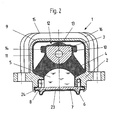
- ein Aggregatelager ohne Schutzdeckel für den Rollbalg;
- Fig. 3
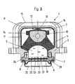
- ein Aggregatelager mit einem Düsenkäfig als Trennwand;
- Fig. 4
- das Aggregatelager nach
Figur 1 in geschnittener Seitenansicht; - Fig. 5
- das Aggregatelager nach
Figur 1 in der Untersicht. -
-
Figur 1 zeigt ein hydraulisch dämpfendes Aggregatelager 1, welches aus einem Auflager 2 und einem Traglager 3 besteht, die durch einen Federkörper 4 aus elastomerem Werkstoff verbunden sind. Das Traglager 3 ist durch einen Kern 10 gebildet, wobei der Kern 10 vom Federkörper 4 vollständig umschlossen ist. Auf der Oberseite 12 des Traglagers 3 befindet sich ein Zuganschlag 13 aus einem elastomeren Werkstoff, der materialeinheitlich mit dem Federkörper 4 ausgeführt ist. Auf beiden Seiten des Kerns 10 befindet sich je ein Queranschlag 14, die ebenfalls materialeinheitlich mit dem Federkörper ausgeführt sind. Der Federkörper 4 und das Auflager 2 begrenzen eine Arbeitskammer 5 und eine Ausgleichskammer 6, die beide mit Dämpfungsflüssigkeit gefüllt sind. Die Arbeitskammer 5 und die Ausgleichskammer 6 sind durch eine Trennwand 7 voneinander getrennt und durch einen Dämpfungskanal 8 strömungsleitend miteinander verbunden. Der Dämpfungskanal 8 ist auf seiner Innenseite mit einer zusätzlichen Beschichtung 26 versehen. Die Ausgleichskammer 6 ist auf der der Arbeitskammer 5 axial abgewandten Seite durch einen Rollbalg 23 begrenzt. Der Rollbalg 23 ist zum Schutz vor Beschädigung auf der der Trennwand 7 axial abgewandten Seite durch einen Deckel 25 abgedeckt. Der Deckel 25 ist mit einstückig und materialeinheitlich mit dem Auflager 2 verbundenen Krallen 24 an dem Auflager 2 befestigt und presst den Rollbalg 23 flüssigkeitsdicht an das Auflager 2 an. Das Auflager 2 weist einen Bügel 9 auf, der einstückig und materialeinheitlich mit dem Auflager 2 verbunden ist. Der Bügel 9 umschließt den Kern 10 und den Federkörper 4 U-förmig. Der Bügel 9 ist auf der dem Traglager 3 und dem Federkörper 4 zugewandten Seite mit einer Beschichtung 11 aus elastomerem Werkstoff versehen. Die Beschichtungen 11 und 26 sowie der Federkörper 4 sind materialeinheitlich und einstückig ausgeführt. Auf der dem Traglager 3 abgewandten Außenseite 15 des Bügels 9 sind Verstärkungsrippen 16 angeordnet, die materialeinheitlich und einstückig mit dem Bügel 9 und dem Auflager 2 ausgeführt sind. -
Figur 2 zeigt ein Aggregatelager gemäßFigur 1 . In diesem Ausführungsbeispiel liegen die Krallen 24 allerdings direkt an dem Rollbalg 23 an und pressen den Rollbalg 23 flüssigkeitsdicht an das Auflager 2 an. -
Figur 3 zeigt ein Aggregatelager gemäßFigur 1 . In diesem Ausführungsbeispiel ist die Trennwand 7 durch einen Düsenkäfig 19 gebildet, der sich aus einer oberen Düsenscheibe 20 und einer unteren Düsenscheibe 21 zusammensetzt. In der unteren Düsenscheibe 21 befindet sich eine Ausnehmung 29. In der Ausnehmung 29 befindet sich eine innerhalb der Ausnehmung 29 frei bewegliche Membran 22. Die Ausnehmung 29 ist auf der dem Arbeitsraum 5 zugewandten Seite durch die oberen Düsenscheibe 20 abgedeckt. Dadurch ist die Membran 22 zwischen den Düsenscheiben 20,21 eingeschlossen. -
Figur 4 zeigt das inFigur 1 beschriebene Aggregatelager in einer Seitenansicht. In dieser Ansicht ist zusätzlich zu dem Dämpfungskanal 8 ein Tilgerkanal 17 zu erkennen. Der Tilgerkanal 17 stellt eine Sackgasse ausgehend von der Arbeitskammer 5 dar. Der Tilgerkanal ist, wie auch der Dämpfungskanal 8 einstückig in das Auflager 2 eingeformt. Der Tilgerkanal 17 ist ebenso wie der Dämpfungskanal 8 mit einer weiteren Beschichtung 30 ausgekleidet. Die weitere Beschichtung 30 ist mit der zusätzlichen Beschichtung 26, dem Federkörper 4 und der Beschichtung 11 materialeinheitlich und einstückig ausgeführt. Die in das Auflager 2 eingeformte Wandung 18 des Tilgerkanals 17 ist in einem Teilstück geöffnet. Die Wandung 18 wird an dieser Stelle durch die weitere Beschichtung 30 gebildet. Die Wandung 18 ist an dieser Stelle elastisch und bildet eine Blähfeder, mit der die Frequenzlage des Tilgerkanals 17 eingestellt werden kann. -
Figur 5 zeigt das inFigur 1 abgebildete Aggregatelager in der Untersicht. In der Ansicht ist der Deckel 25, der Rollbalg 23 und die Trennwand 7 nicht abgebildet. Der Dämpfungskanal 8 und der Tilgerkanal 17 besitzen je eine Öffnung 31,32, durch die der Dämpfungskanal 8 und der Tilgerkanal 17 mit dem Arbeitsraum 5 verbunden sind. Der lange Dämpfungskanal 8 und der kürzere Tilgerkanal 17 verlaufen ringförmig um den Arbeitsraum 5. Beide Kanäle 8, 17 sind materialeinheitlich in das Auflager 2 eingeformt und können in einem Arbeitsgang gemeinsam mit dem Auflager 2 hergestellt werden. In dem Teilschnitt ist die Wandung 18 des Tilgerkanals 17 aus elastomerem Werkstoff abgebildet.
Claims (11)
- Aggregatelager (1), umfassend ein Auflager (2) und ein Traglager (3), die durch einen Federkörper (4) aus elastomeren Werkstoff verbunden sind, wobei das Auflager (2) einen Bügel (9) aufweist, der das Traglager (3) und den Federkörper (4), im Querschnitt betrachtet U-förmig umschließt, wobei das Auflager (2) und der Bügel (9) einstückig und materialeinheitlich ausgeführt sind und wobei das Auflager (2) und der Federkörper (4) eine Arbeitskammer (5) und eine Ausgleichskammer (6) begrenzen, die beide mit Dämpfungsflüssigkeit gefüllt sind, wobei die Arbeitskammer (5) und die Ausgleichskammer (6) durch eine Trennwand (7) voneinander getrennt und durch einen Dämpfungskanal (8) strömungsleitend miteinander verbunden sind, dadurch gekennzeichnet, dass der Dämpfungskanal (8) einstückig in das Auflager (2) eingeformt ist.
- Aggregatelager nach Anspruch 1, dadurch gekennzeichnet, dass das Traglager (3) als Kern (10) ausgebildet ist.
- Aggregatelager nach Anspruch 1 oder 2, dadurch gekennzeichnet, dass der Kern (10), im Querschnitt betrachtet, vom elastomeren Werkstoff des Federkörpers (4) umschlossen ist.
- Aggregatelager nach einem der Ansprüche 1 bis 3, dadurch gekennzeichnet, dass der Bügel (9) auf der dem Traglager (3) und dem Federkörper (4) zugewandten Seite mit einer Beschichtung (11) aus elastomerem Werkstoff versehen ist.
- Aggregatelager nach Anspruch 4, dadurch gekennzeichnet, dass die Beschichtung (11) und der Federkörper (4) einstückig und materialeinheitlich ausgebildet sind.
- Aggregatelager nach einem der Ansprüche 1 bis 5, dadurch gekennzeichnet, dass das Traglager (3) und/oder der Federkörper (4) auf der Oberseite (12) mit einem Zuganschlag (13) und im Querschnitt betrachtet, seitlich mit Queranschlägen (14) versehen ist.
- Aggregatelager nach einem der Ansprüche 1 bis 6, dadurch gekennzeichnet, dass der Bügel (9) auf der dem Traglager (3) und dem Federkörper (4) abgewandten Außenseite (15) Verstärkungsrippen (16) aufweist.
- Aggregatelager nach Anspruch 1, dadurch gekennzeichnet, dass die Arbeitskammer (5) zusätzlich zum Dämpfungskanal (8) mit einem Tilgerkanal (17) hydraulisch verbunden ist.
- Aggregatelager nach Anspruch 8, dadurch gekennzeichnet, dass die, in der Draufsicht betrachtet, radial nach außen gerichtete Wandung (18) des Tilgerkanals (17) zumindest teilweise aus einem elastomeren Werkstoff gebildet ist.
- Aggregatelager nach einem der Ansprüche 1 oder 8 bis 9, dadurch gekennzeichnet, dass die Trennwand (7) als Düsenkäfig (19) ausgebildet ist, umfassend zwei Düsenscheiben (20,21) und eine zwischen den Düsenscheiben (20,21) angeordnete Membran (22).
- Aggregatelager nach einem der Ansprüche 1 oder 8 bis 10, dadurch gekennzeichnet, dass die Ausgleichskammer (6) auf der der Arbeitskammer (5) axial abgewandten Seite durch einen Rollbalg (23) begrenzt ist, wobei der Rollbalg (23) mit einstückig und materialeinheitlich mit dem Auflager (2) verbundenen Krallen (24) flüssigkeitsdicht an dem Auflager (2) befestigt ist.
Applications Claiming Priority (1)
| Application Number | Priority Date | Filing Date | Title |
|---|---|---|---|
| DE102004060499.1A DE102004060499B4 (de) | 2004-12-16 | 2004-12-16 | Aggregatelager |
Publications (2)
| Publication Number | Publication Date |
|---|---|
| EP1672242A1 EP1672242A1 (de) | 2006-06-21 |
| EP1672242B1 true EP1672242B1 (de) | 2010-12-01 |
Family
ID=35841804
Family Applications (1)
| Application Number | Title | Priority Date | Filing Date |
|---|---|---|---|
| EP05023521A Not-in-force EP1672242B1 (de) | 2004-12-16 | 2005-10-27 | Aggregatelager |
Country Status (4)
| Country | Link |
|---|---|
| EP (1) | EP1672242B1 (de) |
| JP (1) | JP2006170447A (de) |
| AT (1) | ATE490420T1 (de) |
| DE (2) | DE102004060499B4 (de) |
Families Citing this family (7)
| Publication number | Priority date | Publication date | Assignee | Title |
|---|---|---|---|---|
| EP1925846A3 (de) * | 2006-11-22 | 2009-07-22 | Carl Freudenberg KG | Hydraulisch dämpfendes Aggregatelager |
| DE102007032957C5 (de) * | 2007-07-14 | 2023-08-17 | Contitech Vibration Control Gmbh | Elastisches Lager |
| DE102008007137A1 (de) | 2008-01-31 | 2009-08-06 | Carl Freudenberg Kg | Hydraulisch dämpfendes Aggregatelager |
| JP6253500B2 (ja) * | 2014-05-07 | 2017-12-27 | 株式会社ブリヂストン | 防振装置 |
| DE102014222929A1 (de) * | 2014-11-11 | 2016-05-12 | Contitech Vibration Control Gmbh | Hydrolager sowie Kraftfahrzeug mit einem derartigen Hydrolager |
| JP6473063B2 (ja) * | 2015-09-28 | 2019-02-20 | 本田技研工業株式会社 | 防振装置 |
| CN113815397B (zh) * | 2021-10-31 | 2023-09-01 | 东风商用车有限公司 | 一种用于商用车的动力总成悬置软垫总成 |
Family Cites Families (10)
| Publication number | Priority date | Publication date | Assignee | Title |
|---|---|---|---|---|
| EP0172700B2 (de) * | 1984-08-07 | 1992-04-22 | Avon Industrial Polymers Limited | Hydraulisch gedämpftes Lager |
| JP2799953B2 (ja) * | 1993-07-06 | 1998-09-21 | 山下ゴム株式会社 | 液封防振装置 |
| DE19537462C2 (de) * | 1995-10-07 | 2003-10-16 | Freudenberg Carl Kg | Aggregatelager |
| EP0896168A1 (de) * | 1997-08-07 | 1999-02-10 | Tokai Rubber Industries, Ltd. | Elastische Befestigungsvorrichtung mit einem Hydrolager und einem Träger aus Kunststoff für das Hydrolager, und Verfahren zur Herstellung |
| FR2778716B1 (fr) * | 1998-05-13 | 2000-08-04 | Peugeot | Support hydroelastique interpose entre un groupe motopropulseur et une caisse d'un vehicule automobile |
| DE10024535B4 (de) * | 2000-05-18 | 2007-04-12 | Trelleborg Automotive Technical Centre Gmbh | Hydraulisch dämpfendes Lager |
| DE10200592A1 (de) * | 2002-01-10 | 2003-07-31 | Freudenberg Carl Kg | Hydraulisch dämpfendes Lager |
| ITTO20020128A1 (it) * | 2002-02-15 | 2003-08-18 | Gomma C F Spa | Supporto idroelastico, particolarmente per un motore a combustione interna. |
| DE10230933A1 (de) * | 2002-07-09 | 2004-01-22 | Bayerische Motoren Werke Ag | Lager zur Abstützung einer Brennkraftmaschine in einem Kraftfahrzeug |
| DE20212151U1 (de) * | 2002-08-07 | 2002-10-10 | Trelleborg Automotive Tech Ct | Hydraulisch dämpfendes Lager |
-
2004
- 2004-12-16 DE DE102004060499.1A patent/DE102004060499B4/de not_active Expired - Fee Related
-
2005
- 2005-10-27 DE DE502005010608T patent/DE502005010608D1/de active Active
- 2005-10-27 EP EP05023521A patent/EP1672242B1/de not_active Not-in-force
- 2005-10-27 AT AT05023521T patent/ATE490420T1/de active
- 2005-12-16 JP JP2005362938A patent/JP2006170447A/ja active Pending
Also Published As
| Publication number | Publication date |
|---|---|
| EP1672242A1 (de) | 2006-06-21 |
| DE502005010608D1 (de) | 2011-01-13 |
| DE102004060499A1 (de) | 2006-07-06 |
| DE102004060499B4 (de) | 2014-01-30 |
| JP2006170447A (ja) | 2006-06-29 |
| ATE490420T1 (de) | 2010-12-15 |
Similar Documents
| Publication | Publication Date | Title |
|---|---|---|
| EP1672242B1 (de) | Aggregatelager | |
| EP0042910B2 (de) | Hydraulisch dämpfendes Einkammerlager | |
| EP0154828B1 (de) | Hydraulisch gedämpftes elastisches Lager, insbesondere für den Antriebsmotor in Kraftfahrzeugen | |
| EP0611901A1 (de) | Hydraulisch dämpfende Lagerbuchse | |
| DE10037954A1 (de) | Hydrolager | |
| DE102016001507A1 (de) | Schwingungstilger | |
| DE4106838A1 (de) | Daempfendes aggregatlager | |
| DE4212190C2 (de) | Elastische Lagerung mit einer Fluidfüllung | |
| EP1287273B1 (de) | Hydraulisch dämpfendes buchsenlager | |
| DE19915798C2 (de) | Schaltbares, hydraulisch dämpfendes Lager | |
| DE3920153C2 (de) | ||
| DE102008007137A1 (de) | Hydraulisch dämpfendes Aggregatelager | |
| EP1347200B1 (de) | Hydrolager | |
| EP1072450A2 (de) | Federbeinstützlager | |
| DE19515838C2 (de) | Hydraulisch dämpfendes Gummilager | |
| EP1925846A2 (de) | Hydraulisch dämpfendes Aggregatelager | |
| EP2060823A2 (de) | Hydrolager | |
| EP0713030A1 (de) | Lager zur dämpfenden Anordnung schwingender Massen | |
| EP0528253B1 (de) | Hydraulisch dämpfendes Stützlager für Fahrwerksteile in Kraftfahrzeugen | |
| EP1055839A2 (de) | Hydraulisch dämpfendes Lager | |
| DE4015213A1 (de) | Schwingungsdaempfungsvorrichtung | |
| EP2730800B1 (de) | Hydrolager | |
| EP0670435B1 (de) | Elastisches Lager | |
| EP0389839B1 (de) | Verspannbares, hydraulisch gedämpftes Lagerelement | |
| DE102004035677B4 (de) | Stützlager mit mindestens zwei miteinander verbundenen Kammern |
Legal Events
| Date | Code | Title | Description |
|---|---|---|---|
| PUAI | Public reference made under article 153(3) epc to a published international application that has entered the european phase |
Free format text: ORIGINAL CODE: 0009012 |
|
| AK | Designated contracting states |
Kind code of ref document: A1 Designated state(s): AT BE BG CH CY CZ DE DK EE ES FI FR GB GR HU IE IS IT LI LT LU LV MC NL PL PT RO SE SI SK TR |
|
| AX | Request for extension of the european patent |
Extension state: AL BA HR MK YU |
|
| 17P | Request for examination filed |
Effective date: 20060608 |
|
| AKX | Designation fees paid |
Designated state(s): AT BE BG CH CY CZ DE DK EE ES FI FR GB GR HU IE IS IT LI LT LU LV MC NL PL PT RO SE SI SK TR |
|
| 17Q | First examination report despatched |
Effective date: 20070425 |
|
| 17Q | First examination report despatched |
Effective date: 20070425 |
|
| GRAP | Despatch of communication of intention to grant a patent |
Free format text: ORIGINAL CODE: EPIDOSNIGR1 |
|
| GRAS | Grant fee paid |
Free format text: ORIGINAL CODE: EPIDOSNIGR3 |
|
| GRAA | (expected) grant |
Free format text: ORIGINAL CODE: 0009210 |
|
| AK | Designated contracting states |
Kind code of ref document: B1 Designated state(s): AT BE BG CH CY CZ DE DK EE ES FI FR GB GR HU IE IS IT LI LT LU LV MC NL PL PT RO SE SI SK TR |
|
| REG | Reference to a national code |
Ref country code: GB Ref legal event code: FG4D Free format text: NOT ENGLISH |
|
| REG | Reference to a national code |
Ref country code: CH Ref legal event code: EP |
|
| REG | Reference to a national code |
Ref country code: IE Ref legal event code: FG4D |
|
| REF | Corresponds to: |
Ref document number: 502005010608 Country of ref document: DE Date of ref document: 20110113 Kind code of ref document: P |
|
| REG | Reference to a national code |
Ref country code: NL Ref legal event code: VDEP Effective date: 20101201 |
|
| PG25 | Lapsed in a contracting state [announced via postgrant information from national office to epo] |
Ref country code: LT Free format text: LAPSE BECAUSE OF FAILURE TO SUBMIT A TRANSLATION OF THE DESCRIPTION OR TO PAY THE FEE WITHIN THE PRESCRIBED TIME-LIMIT Effective date: 20101201 |
|
| LTIE | Lt: invalidation of european patent or patent extension |
Effective date: 20101201 |
|
| PG25 | Lapsed in a contracting state [announced via postgrant information from national office to epo] |
Ref country code: FI Free format text: LAPSE BECAUSE OF FAILURE TO SUBMIT A TRANSLATION OF THE DESCRIPTION OR TO PAY THE FEE WITHIN THE PRESCRIBED TIME-LIMIT Effective date: 20101201 Ref country code: NL Free format text: LAPSE BECAUSE OF FAILURE TO SUBMIT A TRANSLATION OF THE DESCRIPTION OR TO PAY THE FEE WITHIN THE PRESCRIBED TIME-LIMIT Effective date: 20101201 Ref country code: CY Free format text: LAPSE BECAUSE OF FAILURE TO SUBMIT A TRANSLATION OF THE DESCRIPTION OR TO PAY THE FEE WITHIN THE PRESCRIBED TIME-LIMIT Effective date: 20101201 Ref country code: SI Free format text: LAPSE BECAUSE OF FAILURE TO SUBMIT A TRANSLATION OF THE DESCRIPTION OR TO PAY THE FEE WITHIN THE PRESCRIBED TIME-LIMIT Effective date: 20101201 Ref country code: SE Free format text: LAPSE BECAUSE OF FAILURE TO SUBMIT A TRANSLATION OF THE DESCRIPTION OR TO PAY THE FEE WITHIN THE PRESCRIBED TIME-LIMIT Effective date: 20101201 Ref country code: LV Free format text: LAPSE BECAUSE OF FAILURE TO SUBMIT A TRANSLATION OF THE DESCRIPTION OR TO PAY THE FEE WITHIN THE PRESCRIBED TIME-LIMIT Effective date: 20101201 Ref country code: BG Free format text: LAPSE BECAUSE OF FAILURE TO SUBMIT A TRANSLATION OF THE DESCRIPTION OR TO PAY THE FEE WITHIN THE PRESCRIBED TIME-LIMIT Effective date: 20110301 |
|
| REG | Reference to a national code |
Ref country code: IE Ref legal event code: FD4D |
|
| PG25 | Lapsed in a contracting state [announced via postgrant information from national office to epo] |
Ref country code: GR Free format text: LAPSE BECAUSE OF FAILURE TO SUBMIT A TRANSLATION OF THE DESCRIPTION OR TO PAY THE FEE WITHIN THE PRESCRIBED TIME-LIMIT Effective date: 20110302 |
|
| PG25 | Lapsed in a contracting state [announced via postgrant information from national office to epo] |
Ref country code: IS Free format text: LAPSE BECAUSE OF FAILURE TO SUBMIT A TRANSLATION OF THE DESCRIPTION OR TO PAY THE FEE WITHIN THE PRESCRIBED TIME-LIMIT Effective date: 20110401 Ref country code: IE Free format text: LAPSE BECAUSE OF FAILURE TO SUBMIT A TRANSLATION OF THE DESCRIPTION OR TO PAY THE FEE WITHIN THE PRESCRIBED TIME-LIMIT Effective date: 20101201 Ref country code: CZ Free format text: LAPSE BECAUSE OF FAILURE TO SUBMIT A TRANSLATION OF THE DESCRIPTION OR TO PAY THE FEE WITHIN THE PRESCRIBED TIME-LIMIT Effective date: 20101201 Ref country code: EE Free format text: LAPSE BECAUSE OF FAILURE TO SUBMIT A TRANSLATION OF THE DESCRIPTION OR TO PAY THE FEE WITHIN THE PRESCRIBED TIME-LIMIT Effective date: 20101201 Ref country code: ES Free format text: LAPSE BECAUSE OF FAILURE TO SUBMIT A TRANSLATION OF THE DESCRIPTION OR TO PAY THE FEE WITHIN THE PRESCRIBED TIME-LIMIT Effective date: 20110312 Ref country code: PT Free format text: LAPSE BECAUSE OF FAILURE TO SUBMIT A TRANSLATION OF THE DESCRIPTION OR TO PAY THE FEE WITHIN THE PRESCRIBED TIME-LIMIT Effective date: 20110401 |
|
| PG25 | Lapsed in a contracting state [announced via postgrant information from national office to epo] |
Ref country code: SK Free format text: LAPSE BECAUSE OF FAILURE TO SUBMIT A TRANSLATION OF THE DESCRIPTION OR TO PAY THE FEE WITHIN THE PRESCRIBED TIME-LIMIT Effective date: 20101201 Ref country code: PL Free format text: LAPSE BECAUSE OF FAILURE TO SUBMIT A TRANSLATION OF THE DESCRIPTION OR TO PAY THE FEE WITHIN THE PRESCRIBED TIME-LIMIT Effective date: 20101201 Ref country code: RO Free format text: LAPSE BECAUSE OF FAILURE TO SUBMIT A TRANSLATION OF THE DESCRIPTION OR TO PAY THE FEE WITHIN THE PRESCRIBED TIME-LIMIT Effective date: 20101201 |
|
| PLBE | No opposition filed within time limit |
Free format text: ORIGINAL CODE: 0009261 |
|
| STAA | Information on the status of an ep patent application or granted ep patent |
Free format text: STATUS: NO OPPOSITION FILED WITHIN TIME LIMIT |
|
| PG25 | Lapsed in a contracting state [announced via postgrant information from national office to epo] |
Ref country code: DK Free format text: LAPSE BECAUSE OF FAILURE TO SUBMIT A TRANSLATION OF THE DESCRIPTION OR TO PAY THE FEE WITHIN THE PRESCRIBED TIME-LIMIT Effective date: 20101201 |
|
| 26N | No opposition filed |
Effective date: 20110902 |
|
| REG | Reference to a national code |
Ref country code: DE Ref legal event code: R097 Ref document number: 502005010608 Country of ref document: DE Effective date: 20110902 |
|
| PG25 | Lapsed in a contracting state [announced via postgrant information from national office to epo] |
Ref country code: IT Free format text: LAPSE BECAUSE OF FAILURE TO SUBMIT A TRANSLATION OF THE DESCRIPTION OR TO PAY THE FEE WITHIN THE PRESCRIBED TIME-LIMIT Effective date: 20101201 |
|
| BERE | Be: lapsed |
Owner name: CARL FREUDENBERG K.G. Effective date: 20111031 |
|
| PG25 | Lapsed in a contracting state [announced via postgrant information from national office to epo] |
Ref country code: MC Free format text: LAPSE BECAUSE OF NON-PAYMENT OF DUE FEES Effective date: 20111031 |
|
| REG | Reference to a national code |
Ref country code: CH Ref legal event code: PL |
|
| PG25 | Lapsed in a contracting state [announced via postgrant information from national office to epo] |
Ref country code: LI Free format text: LAPSE BECAUSE OF NON-PAYMENT OF DUE FEES Effective date: 20111031 Ref country code: BE Free format text: LAPSE BECAUSE OF NON-PAYMENT OF DUE FEES Effective date: 20111031 Ref country code: CH Free format text: LAPSE BECAUSE OF NON-PAYMENT OF DUE FEES Effective date: 20111031 |
|
| REG | Reference to a national code |
Ref country code: AT Ref legal event code: MM01 Ref document number: 490420 Country of ref document: AT Kind code of ref document: T Effective date: 20111027 |
|
| PG25 | Lapsed in a contracting state [announced via postgrant information from national office to epo] |
Ref country code: AT Free format text: LAPSE BECAUSE OF NON-PAYMENT OF DUE FEES Effective date: 20111027 |
|
| PG25 | Lapsed in a contracting state [announced via postgrant information from national office to epo] |
Ref country code: LU Free format text: LAPSE BECAUSE OF NON-PAYMENT OF DUE FEES Effective date: 20111027 |
|
| PG25 | Lapsed in a contracting state [announced via postgrant information from national office to epo] |
Ref country code: TR Free format text: LAPSE BECAUSE OF FAILURE TO SUBMIT A TRANSLATION OF THE DESCRIPTION OR TO PAY THE FEE WITHIN THE PRESCRIBED TIME-LIMIT Effective date: 20101201 |
|
| PG25 | Lapsed in a contracting state [announced via postgrant information from national office to epo] |
Ref country code: HU Free format text: LAPSE BECAUSE OF FAILURE TO SUBMIT A TRANSLATION OF THE DESCRIPTION OR TO PAY THE FEE WITHIN THE PRESCRIBED TIME-LIMIT Effective date: 20101201 |
|
| REG | Reference to a national code |
Ref country code: FR Ref legal event code: PLFP Year of fee payment: 11 |
|
| REG | Reference to a national code |
Ref country code: FR Ref legal event code: PLFP Year of fee payment: 12 |
|
| REG | Reference to a national code |
Ref country code: DE Ref legal event code: R081 Ref document number: 502005010608 Country of ref document: DE Owner name: VIBRACOUSTIC GMBH, DE Free format text: FORMER OWNER: CARL FREUDENBERG KG, 69469 WEINHEIM, DE |
|
| REG | Reference to a national code |
Ref country code: FR Ref legal event code: PLFP Year of fee payment: 13 |
|
| REG | Reference to a national code |
Ref country code: FR Ref legal event code: PLFP Year of fee payment: 14 |
|
| PGFP | Annual fee paid to national office [announced via postgrant information from national office to epo] |
Ref country code: DE Payment date: 20191105 Year of fee payment: 15 |
|
| PGFP | Annual fee paid to national office [announced via postgrant information from national office to epo] |
Ref country code: FR Payment date: 20191022 Year of fee payment: 15 |
|
| PGFP | Annual fee paid to national office [announced via postgrant information from national office to epo] |
Ref country code: GB Payment date: 20191023 Year of fee payment: 15 |
|
| REG | Reference to a national code |
Ref country code: DE Ref legal event code: R082 Ref document number: 502005010608 Country of ref document: DE Representative=s name: PATENTANWAELTE OLBRICHT, BUCHHOLD, KEULERTZ PA, DE |
|
| REG | Reference to a national code |
Ref country code: DE Ref legal event code: R119 Ref document number: 502005010608 Country of ref document: DE |
|
| GBPC | Gb: european patent ceased through non-payment of renewal fee |
Effective date: 20201027 |
|
| PG25 | Lapsed in a contracting state [announced via postgrant information from national office to epo] |
Ref country code: DE Free format text: LAPSE BECAUSE OF NON-PAYMENT OF DUE FEES Effective date: 20210501 Ref country code: FR Free format text: LAPSE BECAUSE OF NON-PAYMENT OF DUE FEES Effective date: 20201031 |
|
| PG25 | Lapsed in a contracting state [announced via postgrant information from national office to epo] |
Ref country code: GB Free format text: LAPSE BECAUSE OF NON-PAYMENT OF DUE FEES Effective date: 20201027 |