EP1670632B1 - Method and arrangement for friction welding - Google Patents
Method and arrangement for friction welding Download PDFInfo
- Publication number
- EP1670632B1 EP1670632B1 EP20040789958 EP04789958A EP1670632B1 EP 1670632 B1 EP1670632 B1 EP 1670632B1 EP 20040789958 EP20040789958 EP 20040789958 EP 04789958 A EP04789958 A EP 04789958A EP 1670632 B1 EP1670632 B1 EP 1670632B1
- Authority
- EP
- European Patent Office
- Prior art keywords
- oscillation
- oscillator
- current
- electromagnets
- movement
- Prior art date
- Legal status (The legal status is an assumption and is not a legal conclusion. Google has not performed a legal analysis and makes no representation as to the accuracy of the status listed.)
- Active
Links
- 238000000034 method Methods 0.000 title claims abstract description 13
- 238000003466 welding Methods 0.000 title claims abstract description 11
- 230000010355 oscillation Effects 0.000 claims abstract description 39
- 239000004065 semiconductor Substances 0.000 claims description 27
- 238000006073 displacement reaction Methods 0.000 claims description 7
- 230000002401 inhibitory effect Effects 0.000 claims description 4
- 230000005415 magnetization Effects 0.000 claims description 2
- 230000000638 stimulation Effects 0.000 abstract 1
- 238000010586 diagram Methods 0.000 description 4
- 239000003990 capacitor Substances 0.000 description 2
- 230000005284 excitation Effects 0.000 description 2
- 230000001276 controlling effect Effects 0.000 description 1
- 230000007423 decrease Effects 0.000 description 1
- 230000006735 deficit Effects 0.000 description 1
- 230000001419 dependent effect Effects 0.000 description 1
- 238000001514 detection method Methods 0.000 description 1
- 238000013017 mechanical damping Methods 0.000 description 1
- 230000010363 phase shift Effects 0.000 description 1
- 238000003825 pressing Methods 0.000 description 1
- 230000001105 regulatory effect Effects 0.000 description 1
- 238000005070 sampling Methods 0.000 description 1
- 230000001360 synchronised effect Effects 0.000 description 1
- 230000007704 transition Effects 0.000 description 1
Images

Classifications
-
- B—PERFORMING OPERATIONS; TRANSPORTING
- B23—MACHINE TOOLS; METAL-WORKING NOT OTHERWISE PROVIDED FOR
- B23K—SOLDERING OR UNSOLDERING; WELDING; CLADDING OR PLATING BY SOLDERING OR WELDING; CUTTING BY APPLYING HEAT LOCALLY, e.g. FLAME CUTTING; WORKING BY LASER BEAM
- B23K20/00—Non-electric welding by applying impact or other pressure, with or without the application of heat, e.g. cladding or plating
- B23K20/10—Non-electric welding by applying impact or other pressure, with or without the application of heat, e.g. cladding or plating making use of vibrations, e.g. ultrasonic welding
-
- B—PERFORMING OPERATIONS; TRANSPORTING
- B23—MACHINE TOOLS; METAL-WORKING NOT OTHERWISE PROVIDED FOR
- B23K—SOLDERING OR UNSOLDERING; WELDING; CLADDING OR PLATING BY SOLDERING OR WELDING; CUTTING BY APPLYING HEAT LOCALLY, e.g. FLAME CUTTING; WORKING BY LASER BEAM
- B23K20/00—Non-electric welding by applying impact or other pressure, with or without the application of heat, e.g. cladding or plating
- B23K20/12—Non-electric welding by applying impact or other pressure, with or without the application of heat, e.g. cladding or plating the heat being generated by friction; Friction welding
- B23K20/121—Control circuits therefor
-
- B—PERFORMING OPERATIONS; TRANSPORTING
- B29—WORKING OF PLASTICS; WORKING OF SUBSTANCES IN A PLASTIC STATE IN GENERAL
- B29C—SHAPING OR JOINING OF PLASTICS; SHAPING OF MATERIAL IN A PLASTIC STATE, NOT OTHERWISE PROVIDED FOR; AFTER-TREATMENT OF THE SHAPED PRODUCTS, e.g. REPAIRING
- B29C65/00—Joining or sealing of preformed parts, e.g. welding of plastics materials; Apparatus therefor
- B29C65/02—Joining or sealing of preformed parts, e.g. welding of plastics materials; Apparatus therefor by heating, with or without pressure
- B29C65/06—Joining or sealing of preformed parts, e.g. welding of plastics materials; Apparatus therefor by heating, with or without pressure using friction, e.g. spin welding
- B29C65/0609—Joining or sealing of preformed parts, e.g. welding of plastics materials; Apparatus therefor by heating, with or without pressure using friction, e.g. spin welding characterised by the movement of the parts to be joined
- B29C65/0618—Linear
-
- B—PERFORMING OPERATIONS; TRANSPORTING
- B29—WORKING OF PLASTICS; WORKING OF SUBSTANCES IN A PLASTIC STATE IN GENERAL
- B29C—SHAPING OR JOINING OF PLASTICS; SHAPING OF MATERIAL IN A PLASTIC STATE, NOT OTHERWISE PROVIDED FOR; AFTER-TREATMENT OF THE SHAPED PRODUCTS, e.g. REPAIRING
- B29C66/00—General aspects of processes or apparatus for joining preformed parts
- B29C66/90—Measuring or controlling the joining process
- B29C66/95—Measuring or controlling the joining process by measuring or controlling specific variables not covered by groups B29C66/91 - B29C66/94
- B29C66/951—Measuring or controlling the joining process by measuring or controlling specific variables not covered by groups B29C66/91 - B29C66/94 by measuring or controlling the vibration frequency and/or the vibration amplitude of vibrating joining tools, e.g. of ultrasonic welding tools
- B29C66/9515—Measuring or controlling the joining process by measuring or controlling specific variables not covered by groups B29C66/91 - B29C66/94 by measuring or controlling the vibration frequency and/or the vibration amplitude of vibrating joining tools, e.g. of ultrasonic welding tools by measuring their vibration amplitude
-
- B—PERFORMING OPERATIONS; TRANSPORTING
- B29—WORKING OF PLASTICS; WORKING OF SUBSTANCES IN A PLASTIC STATE IN GENERAL
- B29C—SHAPING OR JOINING OF PLASTICS; SHAPING OF MATERIAL IN A PLASTIC STATE, NOT OTHERWISE PROVIDED FOR; AFTER-TREATMENT OF THE SHAPED PRODUCTS, e.g. REPAIRING
- B29C66/00—General aspects of processes or apparatus for joining preformed parts
- B29C66/90—Measuring or controlling the joining process
- B29C66/95—Measuring or controlling the joining process by measuring or controlling specific variables not covered by groups B29C66/91 - B29C66/94
- B29C66/951—Measuring or controlling the joining process by measuring or controlling specific variables not covered by groups B29C66/91 - B29C66/94 by measuring or controlling the vibration frequency and/or the vibration amplitude of vibrating joining tools, e.g. of ultrasonic welding tools
- B29C66/9516—Measuring or controlling the joining process by measuring or controlling specific variables not covered by groups B29C66/91 - B29C66/94 by measuring or controlling the vibration frequency and/or the vibration amplitude of vibrating joining tools, e.g. of ultrasonic welding tools by controlling their vibration amplitude
-
- B—PERFORMING OPERATIONS; TRANSPORTING
- B29—WORKING OF PLASTICS; WORKING OF SUBSTANCES IN A PLASTIC STATE IN GENERAL
- B29C—SHAPING OR JOINING OF PLASTICS; SHAPING OF MATERIAL IN A PLASTIC STATE, NOT OTHERWISE PROVIDED FOR; AFTER-TREATMENT OF THE SHAPED PRODUCTS, e.g. REPAIRING
- B29C66/00—General aspects of processes or apparatus for joining preformed parts
- B29C66/80—General aspects of machine operations or constructions and parts thereof
- B29C66/83—General aspects of machine operations or constructions and parts thereof characterised by the movement of the joining or pressing tools
- B29C66/832—Reciprocating joining or pressing tools
- B29C66/8322—Joining or pressing tools reciprocating along one axis
-
- B—PERFORMING OPERATIONS; TRANSPORTING
- B29—WORKING OF PLASTICS; WORKING OF SUBSTANCES IN A PLASTIC STATE IN GENERAL
- B29C—SHAPING OR JOINING OF PLASTICS; SHAPING OF MATERIAL IN A PLASTIC STATE, NOT OTHERWISE PROVIDED FOR; AFTER-TREATMENT OF THE SHAPED PRODUCTS, e.g. REPAIRING
- B29C66/00—General aspects of processes or apparatus for joining preformed parts
- B29C66/90—Measuring or controlling the joining process
- B29C66/95—Measuring or controlling the joining process by measuring or controlling specific variables not covered by groups B29C66/91 - B29C66/94
- B29C66/951—Measuring or controlling the joining process by measuring or controlling specific variables not covered by groups B29C66/91 - B29C66/94 by measuring or controlling the vibration frequency and/or the vibration amplitude of vibrating joining tools, e.g. of ultrasonic welding tools
- B29C66/9513—Measuring or controlling the joining process by measuring or controlling specific variables not covered by groups B29C66/91 - B29C66/94 by measuring or controlling the vibration frequency and/or the vibration amplitude of vibrating joining tools, e.g. of ultrasonic welding tools characterised by specific vibration frequency values or ranges
-
- B—PERFORMING OPERATIONS; TRANSPORTING
- B29—WORKING OF PLASTICS; WORKING OF SUBSTANCES IN A PLASTIC STATE IN GENERAL
- B29C—SHAPING OR JOINING OF PLASTICS; SHAPING OF MATERIAL IN A PLASTIC STATE, NOT OTHERWISE PROVIDED FOR; AFTER-TREATMENT OF THE SHAPED PRODUCTS, e.g. REPAIRING
- B29C66/00—General aspects of processes or apparatus for joining preformed parts
- B29C66/90—Measuring or controlling the joining process
- B29C66/95—Measuring or controlling the joining process by measuring or controlling specific variables not covered by groups B29C66/91 - B29C66/94
- B29C66/959—Measuring or controlling the joining process by measuring or controlling specific variables not covered by groups B29C66/91 - B29C66/94 characterised by specific values or ranges of said specific variables
- B29C66/9592—Measuring or controlling the joining process by measuring or controlling specific variables not covered by groups B29C66/91 - B29C66/94 characterised by specific values or ranges of said specific variables in explicit relation to another variable, e.g. X-Y diagrams
Definitions
- the invention relates to a method and an arrangement for friction welding, in which one of the parts to be connected by means of an electromagnetic oscillator is vibrated and controlled by a displacement sensor is a swing by alternately magnetizing two oppositely acting electromagnets.
- an alternating current is generated by a generator whose frequency corresponds to half the resonant frequency of the vibrator. Since this also depends on the workpiece holder on the vibrator, a matching of the frequency is required in known devices after a change of the workpiece holder. This is at one off EP 0 481 825 A2 known device provided that the operating frequency of the generator is changed by a microprocessor until the current at a predetermined oscillation amplitude is minimal. However, time passes in which the device does not work optimally. To improve this, it is further provided in the known device that determines the frequency-dependent current curve for a particular tool and stored as a reference becomes. However, this does not yet achieve the shortest possible oscillation time.
- WO 02/076737 A1 Another arrangement for friction welding has become known, in which a vibrator is provided, with which one of the parts to be connected is vibrated and which is driven by oppositely acting electromagnet, wherein an output of the respective position of the vibrator receiving displacement sensor with an input a controller is connected, the output side is connected to inputs of an analog power amplifier for the electromagnets.
- the electromagnets are supplied with voltage for in each case one half-wave of the oscillation.
- a suitable for excitation of the oscillation phase of the magnetization is to be achieved by a caused by the inductance of the electromagnets phase shift. This leads to an inefficient control behavior of the arrangement.
- the method according to the invention makes possible a short welding process time in that, after a controlled oscillation and a predeterminable oscillation time, the oscillator is decelerated in that, as a function of the respective direction of movement of the oscillator during oscillation, an electromagnet supporting the movement and, during deceleration, an electromagnet inhibiting the respective movement Power is applied and that during braking when reaching a predetermined oscillation amplitude of the power is turned off.
- the inventive method is based on the finding that the vibration is terminated as soon as possible after the joining process, so that an impairment of the already made connection is avoided.
- the Controlled oscillation ensures that the resonance frequency adjusts itself fully automatically.
- the switching off of the current upon reaching a predetermined oscillation amplitude prevents Wiederansahwingen with opposite phase.
- the predetermined oscillation amplitude is selected such that the joint is not overloaded during the decay, which is now determined solely by the mechanical damping.
- the steady state can be maintained for a particular time to be determined.
- Particularly good results have been shown in the method according to the invention, when the oscillation and deceleration are each shorter than 80 ms.
- the controller is designed so that it controls the power output stage such that depending on the respective direction of movement of the vibrator, a movement supporting electromagnet is energized, that for braking a respective movement inhibiting Electromagnet energized and that during braking when reaching a predetermined amplitude of vibration, the power is turned off.
- This arrangement allows in a particularly simple manner a controlled oscillation, without a generator is present, the first oscillates on a possibly wrong frequency and then must be synchronized.
- the transition from the oscillation or the steady state to deceleration can be effected in a simple manner by switching the power output stage.
- the power output stage is formed by a first bridge branch of two series-connected semiconductor switches with parallel freewheeling diodes and two further bridge branches from a series circuit of a semiconductor switch and a diode that the coils of the electromagnets between the connection point the semiconductor switch of the first bridge branch on the one hand and a connecting point of the other bridge branches are connected on the other hand, that the semiconductor switch of the first bridge branch with the oscillation frequency and the semiconductor switches of the other bridge branches with a higher than the oscillation frequency pulse width modulated or tolerance band controlled, depending on the control state higher Frequencies can give as the oscillation frequency.
- Some semiconductor switches are switched at the oscillation frequency, for example 270 Hz, other semiconductor switches are repeated several times per oscillation switched, with their switching frequency remains in the range of a few kHz. As a sampling frequency for the detection of the actual values of current and position another frequency of at most 15 kHz is required.
- the semiconductor switches in the further bridge branches are loaded higher than those in the first bridge branch. In order to reduce this load, it can be provided that the current through the electromagnets is interchanged from duty cycle to duty cycle via the further bridge branches.
- Another advantageous embodiment of the arrangement according to the invention is that means for forming a trigger signal for switching the current through the respective electromagnet are formed such that the trigger signal occurs a pre-definable part, preferably a quarter of a period of oscillation after a zero crossing of the oscillation.
- the arrangement according to the invention can be designed in such a way that the regulator has an integral component which is initially preset with a substantial value.
- a further embodiment of the arrangement according to the invention is that the oscillator including its resilient mounting and the workpiece holder, the displacement sensor, the controller, the power amplifier and the electromagnets form a resonant circuit whose resonant frequency substantially from the natural frequency of the vibrator including its resilient mounting and the Workpiece holder is determined. This also contributes to a quick start, at.
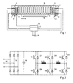
- Fig. 1 shows the necessary parts for explaining the invention of a friction welding device.
- two electromagnets 2, 3 are arranged, which draw a swing frame 4 according to the energization respectively in their direction - in the case of the electromagnet 2 in the direction of the arrow s.
- the swing frame 4 is mounted on the head bridge 1 by means of a spring 5 vibratory.
- the swing frame carries a workpiece holder 6, which is designed depending on the part to be connected and accordingly can be replaced.
- the swing frame 4, the spring 5 and the workpiece holder 6 are also called oscillators for short.
- the head bridge on supports 9, 10 are mounted, which are part of a machine that carries, inter alia, in a manner not shown a receptacle for the other part to be connected, which is pressed for the welding operation to the workpiece holder 6 ,
- a displacement sensor 11 measures the respective position of the oscillating frame and forwards it as a corresponding electrical signal to a controller 12.
- Output signals of the controller 12 are fed to a power output stage 13, which is connected at three-phase to the power grid.
- FIG. 2 An example of the power output stage 13 is in Fig. 2 shown in more detail.
- the supplied at 14 mains voltage is rectified by a three-phase rectifier 15.
- a capacitor 16 serves to smooth the DC voltage and to buffer the pulsating load.
- the arrangement shown is produced in large numbers as a three-phase converter.
- An included in Fig. 2 not shown processor need only be programmed to implement the invention in an appropriate manner.
- the power output stage is provided by two series-connected power transistors T1, T4, T3, T6; T5, T2 formed, each having a freewheeling diode D1, D4; D3, D6; D5, D2 is connected in parallel.
- the middle bridge branch T3, T6 is controlled in each case in dependence on the direction of movement of the vibrator with the oscillation frequency.
- one of the transistors T5 or T4 is in each case connected to a higher one Frequency pulse width modulated or driven according to a tolerance band control of the current.
- the diodes D3 and D6 of the middle bridge branch and the diodes D2 and D1 serve as freewheeling diodes. Details of the conductive phases of the semiconductor switches will be discussed later Fig. 4 explained.
- the diagram a shows the time course of the path s of the oscillator, the diagrams d and c the course of the currents iL (2) and iL (3) of the two electromagnets 2, 3 ( Fig. 1 ).
- the electromagnets are energized in such a way that the oscillation is supported.
- the third half-wave for example, at time t1, a command for braking takes place, whereupon in the following half-wave a waiting pause is formed in that none of the electromagnets is energized.
- each of the electromagnet is energized, which slows the oscillation, so that their amplitude decreases.
- the current is switched off in order to avoid reverse phase excitation.
- Fig. 4 represents a timing diagram of the current i, as well as hatched areas the respective conductive phases of the semiconductor switches.
- the semiconductor switch T6 is largely conductive during the corresponding half-wave of the movement phase.
- the semiconductor switch T5 is clocked, the duty cycle is regulated according to the predetermined oscillation amplitude.
- the current flows through the energy stored in the electromagnet in Freewheel via the diode D2 and the semiconductor switch T6.
- the current flows through the diodes D2 and D3 back into the capacitor and sounds because of its voltage very quickly.
- the electromagnet 3 is energized.
- the conductive phases of the semiconductor switches T3 and T4 and of the diodes D6 and D1 correspond to the conducting phases of the semiconductor switches T6 and T5 as well as the diodes D3 and D2 in the preceding half-cycle.
Landscapes
- Engineering & Computer Science (AREA)
- Mechanical Engineering (AREA)
- Apparatuses For Generation Of Mechanical Vibrations (AREA)
- Lining Or Joining Of Plastics Or The Like (AREA)
- Pressure Welding/Diffusion-Bonding (AREA)
- Arc Welding Control (AREA)
- General Induction Heating (AREA)
Abstract
Description
Die Erfindung betrifft ein Verfahren und eine Anordnung zum Reibungsschweißen, bei welchen eines der zu verbindenden Teile mit Hilfe eines elektromagnetischen Schwingers in Schwingung versetzt wird und gesteuert von einem Wegsensor ein Anschwingen durch abwechselnde Magnetisierung zweier entgegengesetzt wirkender Elektromagnete erfolgt.The invention relates to a method and an arrangement for friction welding, in which one of the parts to be connected by means of an electromagnetic oscillator is vibrated and controlled by a displacement sensor is a swing by alternately magnetizing two oppositely acting electromagnets.
Ein solches Verfahren und eine solche Anordnung sind aus der
Beim Verbinden von Teilen durch Reibungsschweißen wird Wärme dadurch erzeugt, dass die zu verbindenden Teile gegeneinander bei gleichzeitigem Gegeneinanderpressen gerieben werden. Dies hat den Vorteil, dass die Wärme unmittelbar an den miteinander zu verbindenden Flächen entsteht und nicht erst durch die Teile hindurch zur Schweißstelle transportiert werden muss. Zum Erzeugen der Reibungswärme dient ein elektromagnetischer Schwinger, der mit einer Aufnahme für das eine zu verbindende Teil versehen ist, während das andere Teil von einem Hubtisch herangeführt und angepresst wird.When joining parts by friction welding heat is generated by the parts to be joined against each other while simultaneously pressing against each other. This has the advantage that the heat arises directly on the surfaces to be joined together and does not have to be transported through the parts to the weld. To generate the frictional heat is an electromagnetic oscillator, which is provided with a receptacle for the one part to be connected, while the other part is brought from a lifting table and pressed.
Zum Antrieb des Schwingers wird von einem Generator ein Wechselstrom erzeugt, dessen Frequenz der halben Resonanzfrequenz des Schwingers entspricht. Da diese auch von der Werkstückaufnahme am Schwinger abhängt, ist bei bekannten Vorrichtungen nach einem Wechsel der Werkstückaufnahme ein Abgleich der Frequenz erforderlich. Dazu ist bei einer aus
Durch
Das erfindungsgemäße Verfahren ermöglicht eine kurze Schweißprozesszeit dadurch, dass nach einem geregelten Anschwingen und einer vorgebbaren Schwingzeit der Schwinger elektrisch abgebremst wird, dass in Abhängigkeit von der jeweiligen Bewegungsrichtung des Schwingers beim Anschwingen ein die Bewegung unterstützender Elektromagnet und beim Abbremsen ein die jeweilige Bewegung hemmender Elektromagnet mit Strom beaufschlagt wird und dass während des Abbremsens bei Erreichen einer vorgegebenen Schwingungsamplitude der Strom abgeschaltet wird.The method according to the invention makes possible a short welding process time in that, after a controlled oscillation and a predeterminable oscillation time, the oscillator is decelerated in that, as a function of the respective direction of movement of the oscillator during oscillation, an electromagnet supporting the movement and, during deceleration, an electromagnet inhibiting the respective movement Power is applied and that during braking when reaching a predetermined oscillation amplitude of the power is turned off.
Das erfindungsgemäße Verfahren beruht auf der Erkenntnis, dass die Vibration möglichst unmittelbar nach dem Fügevorgang beendet wird, damit eine Beeinträchtigung der bereits erfolgten Verbindung vermieden wird. Außerdem wird durch das geregelte Anschwingen sichergestellt, dass sich die Resonanzfrequenz unmittelbar vollautomatisch einstellt.The inventive method is based on the finding that the vibration is terminated as soon as possible after the joining process, so that an impairment of the already made connection is avoided. In addition, by the Controlled oscillation ensures that the resonance frequency adjusts itself fully automatically.
Das Abschalten des Stroms bei Erreichen einer vorgegebenen Schwingungsamplitude verhindert ein Wiederansahwingen mit entgegengesetzter Phasenlage. Dabei wird die vorgegebene Schwingungsamplitude derart gewählt, dass während des nunmehr lediglich durch die mechanische Dämpfung bestimmten Ausschwingens die Fügestelle nicht überlastet wird.The switching off of the current upon reaching a predetermined oscillation amplitude prevents Wiederansahwingen with opposite phase. In this case, the predetermined oscillation amplitude is selected such that the joint is not overloaded during the decay, which is now determined solely by the mechanical damping.
Je nach Voraussetzungen im Einzelnen kann der eingeschwungene Zustand für eine jeweils zu bestimmende Zeit aufrechterhalten werden. Besonders gute Ergebnisse haben sich bei dem erfindungsgemäßen Verfahren dann gezeigt, wenn das Anschwingen und das Abbremsen jeweils kürzer als 80 ms sind.Depending on the requirements in detail, the steady state can be maintained for a particular time to be determined. Particularly good results have been shown in the method according to the invention, when the oscillation and deceleration are each shorter than 80 ms.
Bei einer erfindungsgemäßen Anordnung zum Reibungsschweißen ist vorgesehen, dass der Regler so ausgebildet ist, dass er die Leistungsendstufe derart ansteuert, dass in Abhängigkeit von der jeweiligen Bewegungsrichtung des Schwingers ein die Bewegung unterstützender Elektromagnet mit Strom beaufschlagt wird, dass zum Abbremsen ein die jeweilige Bewegung hemmender Elektromagnet mit Strom beaufschlagt und dass während des Abbremsens bei Erreichen einer vorgegebenen Schwingungsamplitude der Strom abgeschaltet wird.In an inventive arrangement for friction welding is provided that the controller is designed so that it controls the power output stage such that depending on the respective direction of movement of the vibrator, a movement supporting electromagnet is energized, that for braking a respective movement inhibiting Electromagnet energized and that during braking when reaching a predetermined amplitude of vibration, the power is turned off.
Diese Anordnung ermöglicht in besonders einfacher Weise ein geregeltes Anschwingen, ohne dass ein Generator vorhanden ist, der erst auf einer eventuell falschen Frequenz anschwingt und danach synchronisiert werden muss.This arrangement allows in a particularly simple manner a controlled oscillation, without a generator is present, the first oscillates on a possibly wrong frequency and then must be synchronized.
Bei der erfindungsgemäßen Anordnung kann der Übergang vom Anschwingen bzw. vom eingeschwungenen Zustand zum Abbremsen in einfacher Weise durch Umschalten der Leistungsendstufe bewirkt werden.In the arrangement according to the invention, the transition from the oscillation or the steady state to deceleration can be effected in a simple manner by switching the power output stage.
Eine vorteilhafte Ausgestaltung der erfindungsgemäßen Anordnung besteht darin, dass die Leistungsendstufe von einem ersten Brückenzweig aus zwei in Reihe geschalteten Halbleiterschaltern mit parallel geschalteten Freilaufdioden und zwei weiteren Brückenzweigen aus je einer Reihenschaltung eines Halbleiterschalters und einer Diode gebildet ist, dass die Spulen der Elektromagnete zwischen den Verbindungspunkt der Halbleiterschalter des ersten Brückenzweiges einerseits und jeweils einen Verbindungspunkt der weiteren Brückenzweigen andererseits geschaltet sind, dass die Halbleiterschalter des ersten Brückenzweiges mit der Schwingfrequenz und die Halbleiterschalter der weiteren Brückenzweige mit einer höheren als die Schwingfrequenz pulsbreitenmoduliert oder toleranzbandgeregelt angesteuert werden, wobei sich je nach Regelzustand höhere Frequenzen als die Schwingfrequenz ergeben können.An advantageous embodiment of the arrangement according to the invention is that the power output stage is formed by a first bridge branch of two series-connected semiconductor switches with parallel freewheeling diodes and two further bridge branches from a series circuit of a semiconductor switch and a diode that the coils of the electromagnets between the connection point the semiconductor switch of the first bridge branch on the one hand and a connecting point of the other bridge branches are connected on the other hand, that the semiconductor switch of the first bridge branch with the oscillation frequency and the semiconductor switches of the other bridge branches with a higher than the oscillation frequency pulse width modulated or tolerance band controlled, depending on the control state higher Frequencies can give as the oscillation frequency.
Wegen bei jedem Schaltvorgang in Halbleiterschaltungen auftretender Verluste und zur Vermeidung elektromagnetischer Störungen ist man bestrebt, die Schaltfrequenzen möglichst gering zu wählen. Das ist mit dieser Ausgestaltung in vorteilhafter Weise möglich. Einige Halbleiterschalter werden mit der Schwingfrequenz, beispielsweise 270 Hz, geschaltet, andere Halbleiterschalter werden mehrmals pro Schwingung geschaltet, wobei deren Schaltfrequenz im Bereich weniger kHz bleibt. Als Abtastfrequenz für die Erfassung der Istwerte von Strom und Lage ist eine weitere Frequenz von höchstens 15 kHz erforderlich.Because occurring in each switching operation in semiconductor circuits losses and to avoid electromagnetic interference is anxious to choose the switching frequencies as low as possible. This is possible with this embodiment in an advantageous manner. Some semiconductor switches are switched at the oscillation frequency, for example 270 Hz, other semiconductor switches are repeated several times per oscillation switched, with their switching frequency remains in the range of a few kHz. As a sampling frequency for the detection of the actual values of current and position another frequency of at most 15 kHz is required.
Auch wenn bei dieser vorteilhaften Ausgestaltung nicht alle Brückenzweige vollständig mit Halbleiterschaltern ausgestaltet werden müssen, kann es wegen der günstig auf dem Markt zur Verfügung stehenden Baugruppen vorteilhaft sein, wenn die Dioden von Halbleiterschaltern mit parallel geschalteten Freilaufdioden gebildet sind.Although in this advantageous embodiment, not all bridge branches must be completely configured with semiconductor switches, it may be advantageous because of the inexpensive available on the market modules when the diodes are formed by semiconductor switches with parallel-connected freewheeling diodes.
Durch das häufigere Schalten werden die Halbleiterschalter in den weiteren Brückenzweigen höher als diejenigen im ersten Brückenzweig belastet. Zur Verringerung dieser Belastung kann vorgesehen sein, dass von Arbeitszyklus zu Arbeitszyklus der Strom durch die Elektromagnete über die weiteren Brückenzweige vertauscht wird.Due to the more frequent switching, the semiconductor switches in the further bridge branches are loaded higher than those in the first bridge branch. In order to reduce this load, it can be provided that the current through the electromagnets is interchanged from duty cycle to duty cycle via the further bridge branches.
Eine andere vorteilhafte Ausgestaltung der erfindungsgemäßen Anordnung besteht darin, dass Mittel zur Bildung eines Triggersignals zum Schalten des Stroms durch den jeweiligen Elektromagneten derart ausgebildet sind, dass das Triggersignal einen vorbestimmbaren Teil, vorzugsweise einem Viertel, einer Schwingungsdauer nach einem Nulldurchgang der Schwingung auftritt.Another advantageous embodiment of the arrangement according to the invention is that means for forming a trigger signal for switching the current through the respective electromagnet are formed such that the trigger signal occurs a pre-definable part, preferably a quarter of a period of oscillation after a zero crossing of the oscillation.
Im Sinne eines möglichst schnellen Anschwingens kann die erfindungsgemäße Anordnung derart ausgestaltet sein, dass der Regler einen Integralanteil aufweist, der zu Beginn mit einem wesentlichen Wert vorbesetzt ist.In terms of the fastest possible oscillation, the arrangement according to the invention can be designed in such a way that the regulator has an integral component which is initially preset with a substantial value.
Eine weitere Ausgestaltung der erfindungsgemäßen Anordnung besteht darin, dass der Schwinger einschließlich dessen federnder Lagerung und der Werkstückaufnahme, der Wegsensor, der Regler, die Leistungsendstufe und die Elektromagnete einen Schwingkreis bilden, dessen Resonanzfrequenz im Wesentlichen von der Eigenfrequenz des Schwingers einschließlich dessen federnder Lagerung und der Werkstückaufnahme bestimmt ist. Dies trägt ebenfalls zu einem schnellen Anschwingen,bei.A further embodiment of the arrangement according to the invention is that the oscillator including its resilient mounting and the workpiece holder, the displacement sensor, the controller, the power amplifier and the electromagnets form a resonant circuit whose resonant frequency substantially from the natural frequency of the vibrator including its resilient mounting and the Workpiece holder is determined. This also contributes to a quick start, at.
Ausführungsbeispiele der Erfindung sind in der Zeichnung anhand mehrerer Figuren dargestellt und in der nachfolgenden Beschreibung näher erläutert. Es zeigt:
-
Fig. 1 eine schematische Darstellung eines Ausführungsbeispiels, -
Fig. 2 eine bei der erfindungsgemäßen Anordnung besonders vorteilhaft verwendbare Leistungsendstufe, -
Fig. 3 Zeitdiagramme zur Erläuterung des Schwingvorgangs und -
Fig. 4 eine Darstellung der Leitend-Phasen der Halbleiterschalter der Leistungsendstufe.
-
Fig. 1 a schematic representation of an embodiment, -
Fig. 2 a particularly useful in the inventive arrangement power output stage, -
Fig. 3 Timing diagrams for explaining the oscillation process and -
Fig. 4 a representation of the Leitend phases of the semiconductor switches of the power amplifier.
Mit Hilfe von Winkeln 7, 8 ist die Kopfbrücke auf Träger 9, 10 montiert, die Teil einer Maschine sind, die unter anderem in nicht dargestellter Weise eine Aufnahme für das andere zu verbindende Teil trägt, die für den Schweißvorgang an die Werkstückaufnahme 6 angepresst wird. Ein Wegaufnehmer 11 misst die jeweilige Position des Schwingrahmens und leitet sie als entsprechendes elektrisches Signal an einen Regler 12 weiter. Ausgangssignale des Reglers 12 werden einer Leistungsendstufe 13 zugeführt, welche bei 14 dreiphasig an das Stromnetz angeschlossen ist.With the help of
Ein Beispiel für die Leistungsendstufe 13 ist in
Die Leistungsendstufe wird von jeweils zwei in Reihe geschalteten Leistungstransistoren T1, T4, T3, T6; T5, T2 gebildet, denen jeweils eine Freilaufdiode D1, D4; D3, D6; D5, D2 parallel geschaltet ist. Der mittlere Brückenzweig T3, T6 wird jeweils in Abhängigkeit von der Bewegungsrichtung des Schwingers mit der Schwingfrequenz gesteuert. Zur Regelung der Schwingungsamplitude wird jeweils einer der Transistoren T5 oder T4 mit einer höheren Frequenz pulsbreitenmoduliert oder gemäß einer Toleranzbandregelung des Stroms angesteuert. Die Dioden D3 bzw. D6 des mittleren Brückenzweiges sowie die Dioden D2 und D1 dienen dabei als Freilaufdioden. Einzelheiten zu den Leitend-Phasen der Halbleiterschalter werden später im Zusammenhang mit
Zunächst wird jedoch das erfindungsgemäße Verfahren anhand von
In der folgenden Halbwelle wird der Elektromagnet 3 bestromt. Die Leitend-Phasen der Halbleiterschalter T3 und T4 sowie der Dioden D6 und D1 entsprechen den Leitend-Phasen der Halbleiterschalter T6 und T5 sowie der Dioden D3 und D2 in der vorangegangenen Halbwelle.In the following half-wave, the
Claims (9)
- Method for friction welding in which one of the parts to be joined is set in oscillation with the aid of an electromagnetic oscillator (4, 5, 6) and initial oscillation takes place by alternating magnetization of two oppositely acting electromagnets (2, 3) under the control of a displacement sensor (11), characterized in that, after a controlled initial oscillation and a predeterminable oscillating time, the oscillator (4, 5, 6) is electrically braked, in that, depending on the respective direction of movement of the oscillator (4, 5, 6), during initial oscillation current is applied to an electromagnet (2, 3) assisting the movement and during braking current is applied to an electromagnet (2, 3) inhibiting the respective movement, and in that during the braking the current is switched off when a predetermined oscillation amplitude is reached.
- Method according to Claim 1, characterized in that the initial oscillation and the braking are each shorter than 80 ms.
- Arrangement for friction welding in which an oscillator (4, 5, 6) is provided, with which one of the parts to be joined is set in oscillation and which is driven by oppositely acting electromagnets (2, 3), an output of a displacement sensor (11) that picks up the respective position of the oscillator (4, 5, 6) being connected to an input of a controller (12), which is connected on the output side to inputs of a power output stage (13) for the electromagnets (2, 3), characterized in that the controller (12) is formed such that it activates the power output stage (13) in such a way that, depending on the respective direction of movement of the oscillator (4, 5, 6), current is applied to an electromagnet (2, 3) assisting the movement, that, for braking, current is applied to an electromagnet (2, 3) inhibiting the respective movement and that, during the braking, the current is switched off when a predetermined oscillation amplitude is reached.
- Arrangement according to Claim 3, characterized in that the power output stage (13) is formed by a first bridge arm comprising two series-connected semiconductor switches (T3, T6) with parallel-connected freewheeling diodes (D3, D6) and two further bridge arms each comprising a series connection of a semiconductor switch (T1, T2) and a diode (D4, D5), in that the coils of the electromagnets (2, 3) are connected between the connecting point of the semiconductor switches (T3, T6) of the first bridge arm on the one hand and in each case a connecting point of the further bridge arms on the other hand, in that the semiconductor switches (T3, T6) of the first bridge arm are activated with the oscillating frequency and the semiconductor switches (T1, T2) of the further bridge arms are activated under pulse-width modulation or tolerance-band control, possibly resulting in frequencies higher than the oscillating frequency, depending on the controlled condition.
- Arrangement according to Claim 4, characterized in that the diodes (D4, D5) are formed by semiconductor switches (T4, T5) with parallel-connected freewheeling diodes (D4, D5).
- Arrangement according to Claim 5, characterized in that, from working cycle to working cycle, the current through the electromagnets (2, 3) is changed over via the further bridge arms.
- Arrangement according to one of Claims 3 to 6, characterized in that means for forming a trigger signal for switching the current through the respective electromagnets (2, 3) are formed by the trigger signal occurring a predeterminable fraction, preferably a quarter, of an oscillating period after a zero crossing of the oscillation.
- Arrangement according to one of Claims 3 to 7, characterized in that the controller (12) has an integral component, which at the beginning is preset with a significant value.
- Arrangement according to one of Claims 3 to 8, characterized in that the oscillator (4, 5, 6), including the resilient mounting (5) thereof, and the work holder (6), the displacement sensor (11), the controller (12), the power output stage (13) and the electromagnets (2, 3) form an oscillating circuit, the resonant frequency of which is substantially determined by the natural frequency of the oscillator (4, 5, 6), including the resilient mounting (5) thereof and the work holder (6).
Applications Claiming Priority (2)
| Application Number | Priority Date | Filing Date | Title |
|---|---|---|---|
| DE2003147345 DE10347345B4 (en) | 2003-10-11 | 2003-10-11 | Method and arrangement for friction welding |
| PCT/DE2004/002252 WO2005035227A1 (en) | 2003-10-11 | 2004-10-11 | Method and arrangement for friction welding |
Publications (2)
| Publication Number | Publication Date |
|---|---|
| EP1670632A1 EP1670632A1 (en) | 2006-06-21 |
| EP1670632B1 true EP1670632B1 (en) | 2010-05-05 |
Family
ID=34428327
Family Applications (1)
| Application Number | Title | Priority Date | Filing Date |
|---|---|---|---|
| EP20040789958 Active EP1670632B1 (en) | 2003-10-11 | 2004-10-11 | Method and arrangement for friction welding |
Country Status (11)
| Country | Link |
|---|---|
| US (1) | US20070131735A1 (en) |
| EP (1) | EP1670632B1 (en) |
| JP (1) | JP2007508158A (en) |
| KR (1) | KR20060120088A (en) |
| CN (1) | CN1867445A (en) |
| AT (1) | ATE466719T1 (en) |
| BR (1) | BRPI0415258A (en) |
| DE (2) | DE10347345B4 (en) |
| ES (1) | ES2345890T3 (en) |
| PT (1) | PT1670632E (en) |
| WO (1) | WO2005035227A1 (en) |
Families Citing this family (10)
| Publication number | Priority date | Publication date | Assignee | Title |
|---|---|---|---|---|
| DE10347984A1 (en) * | 2003-10-15 | 2005-05-19 | Branson Ultraschall Niederlassung Der Emerson Technologies Gmbh & Co | Vibration welding method with shortened settling time |
| CN100368139C (en) * | 2006-01-26 | 2008-02-13 | 中南大学 | Supersonic stirring welding method and its device |
| CN100448590C (en) * | 2006-12-29 | 2009-01-07 | 西北工业大学 | Friction pressure loading mechanism of linear friction welding machine |
| US20120006810A1 (en) * | 2010-07-09 | 2012-01-12 | GM Global Technology Operations LLC | Induction heating-assisted vibration welding method and apparatus |
| US8245748B2 (en) * | 2010-07-14 | 2012-08-21 | Dukane Corporation | Vibration welding system |
| CN102649313A (en) * | 2012-03-30 | 2012-08-29 | 苏州凯尔博精密机械有限公司 | Vibration head used for vibration friction welding machine |
| DE102013102322B4 (en) * | 2013-03-08 | 2018-05-30 | Osram Opto Semiconductors Gmbh | Method and device for measuring and optimizing an optoelectronic component |
| DE102015122314B3 (en) * | 2015-12-18 | 2016-12-15 | Pewag Austria Gmbh | linear friction |
| CN110170737A (en) * | 2019-05-30 | 2019-08-27 | 苏州英威腾电力电子有限公司 | A kind of vibration friction welding method, system and relevant apparatus |
| CN113478065A (en) * | 2021-06-30 | 2021-10-08 | 苏州英威腾电力电子有限公司 | Control method and control circuit of multiplexing H-bridge circuit and friction welding device |
Family Cites Families (7)
| Publication number | Priority date | Publication date | Assignee | Title |
|---|---|---|---|---|
| US4715523A (en) * | 1984-11-12 | 1987-12-29 | Lebedev Vladimir K | Electromagnetic power drive for a friction welding machine |
| DD288338A5 (en) * | 1989-10-06 | 1991-03-28 | Ingenieurhochschule Koethen,De | DEVICE FOR CONTROLLING THE READING TIME OF FRICTION WELDING MACHINES |
| DE4001367A1 (en) * | 1990-01-18 | 1991-09-19 | Branson Ultraschall | DEVICE FOR SETTING A MACHINE PARAMETER IN FRICTION WELDING |
| DE19512820B4 (en) * | 1995-04-05 | 2005-11-03 | Branson Ultraschall Niederlassung Der Emerson Technologies Gmbh & Co | Method and device for adjusting the operating frequency of an orbital vibration welding system |
| US6404154B2 (en) * | 1998-06-02 | 2002-06-11 | Emerson Electric Co. | Force control system |
| US6091215A (en) * | 1998-06-02 | 2000-07-18 | Switched Reluctance Drives Limited | Trajectory controller |
| US6824040B2 (en) * | 2001-03-21 | 2004-11-30 | Forward Technology Industries, Inc. | Method and apparatus for linear vibration welding |
-
2003
- 2003-10-11 DE DE2003147345 patent/DE10347345B4/en not_active Revoked
-
2004
- 2004-10-11 AT AT04789958T patent/ATE466719T1/en not_active IP Right Cessation
- 2004-10-11 PT PT04789958T patent/PT1670632E/en unknown
- 2004-10-11 CN CNA2004800296931A patent/CN1867445A/en active Pending
- 2004-10-11 WO PCT/DE2004/002252 patent/WO2005035227A1/en active Application Filing
- 2004-10-11 ES ES04789958T patent/ES2345890T3/en active Active
- 2004-10-11 BR BRPI0415258 patent/BRPI0415258A/en not_active IP Right Cessation
- 2004-10-11 US US10/573,927 patent/US20070131735A1/en not_active Abandoned
- 2004-10-11 DE DE200450011139 patent/DE502004011139D1/de active Active
- 2004-10-11 EP EP20040789958 patent/EP1670632B1/en active Active
- 2004-10-11 JP JP2006529631A patent/JP2007508158A/en active Pending
- 2004-10-11 KR KR1020067008994A patent/KR20060120088A/en not_active Application Discontinuation
Also Published As
| Publication number | Publication date |
|---|---|
| KR20060120088A (en) | 2006-11-24 |
| CN1867445A (en) | 2006-11-22 |
| ATE466719T1 (en) | 2010-05-15 |
| US20070131735A1 (en) | 2007-06-14 |
| PT1670632E (en) | 2010-07-28 |
| ES2345890T3 (en) | 2010-10-05 |
| WO2005035227A1 (en) | 2005-04-21 |
| BRPI0415258A (en) | 2006-12-12 |
| DE10347345B4 (en) | 2006-06-14 |
| JP2007508158A (en) | 2007-04-05 |
| EP1670632A1 (en) | 2006-06-21 |
| DE10347345A1 (en) | 2005-05-12 |
| DE502004011139D1 (en) | 2010-06-17 |
Similar Documents
| Publication | Publication Date | Title |
|---|---|---|
| EP1670632B1 (en) | Method and arrangement for friction welding | |
| AT412388B (en) | METHOD FOR REGULATING A WELDING CURRENT SOURCE WITH A RESONANCE CIRCUIT | |
| EP1935213B1 (en) | Method for operating an induction heating device | |
| DE102009027688A1 (en) | Hand held power tool | |
| DE3642634A1 (en) | SINGLE-STOCK DC CONVERTER WITH LOSS-FREE SWITCHING | |
| EP0136968A2 (en) | Control device for driving an electromagnet with a starting current followed by a holding current | |
| DE3109073A1 (en) | POWER SUPPLY DEVICE | |
| DE69730505T2 (en) | OPERATING AND CONTROL METHOD AND DEVICE, ESPECIALLY FOR SYNCHRONOUS, PERMANENT MAGNET MOTORS | |
| EP2058109A2 (en) | Ultrasound welding device | |
| DE3139523C2 (en) | Control device for a vibrating armature motor | |
| EP1168626B1 (en) | Method for reducing the settling and rise times in oscillating circuits | |
| DE102004010331A1 (en) | Method and device for generating an electrical heating current, in particular for inductive heating of a workpiece | |
| DE2347935B2 (en) | Device for generating ignition signals for a controllable rectifier | |
| EP1103350B1 (en) | Machine tool with electromagnet for mounting on a ferromagnetic workpiece | |
| DE2016198A1 (en) | Circuit arrangement for controlling electric stepper motors or step magnet arrangements | |
| DE3417280C2 (en) | ||
| DE1538042C3 (en) | Circuit arrangement for converting an alternating voltage into a higher-frequency alternating voltage | |
| DE102009037693A1 (en) | High frequency surgery generator comprises power supply with storage capacitor, where controllable switching device is equipped with energy storage, such as transformer | |
| DE3709250A1 (en) | Invertor for supplying a load with an inductive component | |
| DE4330805A1 (en) | Alternating current source for arc welding processes | |
| DE4207362A1 (en) | DC drive emergency braking circuit - has pulse controller supplying excitation current during emergency braking with extra controller for armature current | |
| DE102014007670B4 (en) | System and method for vibration welding | |
| DE1538043C (en) | Circuit arrangement for converting an alternating voltage lower frequency into such a higher frequency | |
| DE2201495A1 (en) | Mechanical-electrical control device for feeding a load from an alternating current source | |
| DE3025421A1 (en) | Current supply circuit for mains operated gas discharge lamps - has rectifier stage supplying support capacitor, and series connection of switching transistors with parallel charge capacitor |
Legal Events
| Date | Code | Title | Description |
|---|---|---|---|
| PUAI | Public reference made under article 153(3) epc to a published international application that has entered the european phase |
Free format text: ORIGINAL CODE: 0009012 |
|
| 17P | Request for examination filed |
Effective date: 20060112 |
|
| AK | Designated contracting states |
Kind code of ref document: A1 Designated state(s): AT BE BG CH CY CZ DE DK EE ES FI FR GB GR HU IE IT LI LU MC NL PL PT RO SE SI SK TR |
|
| DAX | Request for extension of the european patent (deleted) | ||
| 17Q | First examination report despatched |
Effective date: 20080331 |
|
| GRAP | Despatch of communication of intention to grant a patent |
Free format text: ORIGINAL CODE: EPIDOSNIGR1 |
|
| GRAS | Grant fee paid |
Free format text: ORIGINAL CODE: EPIDOSNIGR3 |
|
| GRAA | (expected) grant |
Free format text: ORIGINAL CODE: 0009210 |
|
| AK | Designated contracting states |
Kind code of ref document: B1 Designated state(s): AT BE BG CH CY CZ DE DK EE ES FI FR GB GR HU IE IT LI LU MC NL PL PT RO SE SI SK TR |
|
| REG | Reference to a national code |
Ref country code: GB Ref legal event code: FG4D Free format text: NOT ENGLISH |
|
| REG | Reference to a national code |
Ref country code: CH Ref legal event code: EP |
|
| REG | Reference to a national code |
Ref country code: IE Ref legal event code: FG4D Free format text: LANGUAGE OF EP DOCUMENT: GERMAN |
|
| REF | Corresponds to: |
Ref document number: 502004011139 Country of ref document: DE Date of ref document: 20100617 Kind code of ref document: P |
|
| RAP2 | Party data changed (patent owner data changed or rights of a patent transferred) |
Owner name: KLN ULTRASCHALL AG |
|
| REG | Reference to a national code |
Ref country code: PT Ref legal event code: SC4A Free format text: AVAILABILITY OF NATIONAL TRANSLATION Effective date: 20100721 |
|
| REG | Reference to a national code |
Ref country code: NL Ref legal event code: VDEP Effective date: 20100505 |
|
| REG | Reference to a national code |
Ref country code: ES Ref legal event code: FG2A Ref document number: 2345890 Country of ref document: ES Kind code of ref document: T3 |
|
| PG25 | Lapsed in a contracting state [announced via postgrant information from national office to epo] |
Ref country code: SE Free format text: LAPSE BECAUSE OF FAILURE TO SUBMIT A TRANSLATION OF THE DESCRIPTION OR TO PAY THE FEE WITHIN THE PRESCRIBED TIME-LIMIT Effective date: 20100505 Ref country code: NL Free format text: LAPSE BECAUSE OF FAILURE TO SUBMIT A TRANSLATION OF THE DESCRIPTION OR TO PAY THE FEE WITHIN THE PRESCRIBED TIME-LIMIT Effective date: 20100505 |
|
| PG25 | Lapsed in a contracting state [announced via postgrant information from national office to epo] |
Ref country code: FI Free format text: LAPSE BECAUSE OF FAILURE TO SUBMIT A TRANSLATION OF THE DESCRIPTION OR TO PAY THE FEE WITHIN THE PRESCRIBED TIME-LIMIT Effective date: 20100505 Ref country code: SI Free format text: LAPSE BECAUSE OF FAILURE TO SUBMIT A TRANSLATION OF THE DESCRIPTION OR TO PAY THE FEE WITHIN THE PRESCRIBED TIME-LIMIT Effective date: 20100505 |
|
| REG | Reference to a national code |
Ref country code: SK Ref legal event code: T3 Ref document number: E 7933 Country of ref document: SK |
|
| REG | Reference to a national code |
Ref country code: IE Ref legal event code: FD4D |
|
| PG25 | Lapsed in a contracting state [announced via postgrant information from national office to epo] |
Ref country code: CY Free format text: LAPSE BECAUSE OF FAILURE TO SUBMIT A TRANSLATION OF THE DESCRIPTION OR TO PAY THE FEE WITHIN THE PRESCRIBED TIME-LIMIT Effective date: 20100505 Ref country code: GR Free format text: LAPSE BECAUSE OF FAILURE TO SUBMIT A TRANSLATION OF THE DESCRIPTION OR TO PAY THE FEE WITHIN THE PRESCRIBED TIME-LIMIT Effective date: 20100806 Ref country code: PL Free format text: LAPSE BECAUSE OF FAILURE TO SUBMIT A TRANSLATION OF THE DESCRIPTION OR TO PAY THE FEE WITHIN THE PRESCRIBED TIME-LIMIT Effective date: 20100505 |
|
| PG25 | Lapsed in a contracting state [announced via postgrant information from national office to epo] |
Ref country code: DK Free format text: LAPSE BECAUSE OF FAILURE TO SUBMIT A TRANSLATION OF THE DESCRIPTION OR TO PAY THE FEE WITHIN THE PRESCRIBED TIME-LIMIT Effective date: 20100505 Ref country code: EE Free format text: LAPSE BECAUSE OF FAILURE TO SUBMIT A TRANSLATION OF THE DESCRIPTION OR TO PAY THE FEE WITHIN THE PRESCRIBED TIME-LIMIT Effective date: 20100505 Ref country code: IE Free format text: LAPSE BECAUSE OF FAILURE TO SUBMIT A TRANSLATION OF THE DESCRIPTION OR TO PAY THE FEE WITHIN THE PRESCRIBED TIME-LIMIT Effective date: 20100505 |
|
| PLBI | Opposition filed |
Free format text: ORIGINAL CODE: 0009260 |
|
| PG25 | Lapsed in a contracting state [announced via postgrant information from national office to epo] |
Ref country code: RO Free format text: LAPSE BECAUSE OF FAILURE TO SUBMIT A TRANSLATION OF THE DESCRIPTION OR TO PAY THE FEE WITHIN THE PRESCRIBED TIME-LIMIT Effective date: 20100505 Ref country code: CZ Free format text: LAPSE BECAUSE OF FAILURE TO SUBMIT A TRANSLATION OF THE DESCRIPTION OR TO PAY THE FEE WITHIN THE PRESCRIBED TIME-LIMIT Effective date: 20100505 |
|
| 26 | Opposition filed |
Opponent name: BRANSON ULTRASCHALL NIEDERLASSUNG DER EMERSON TECH Effective date: 20110207 |
|
| PLAX | Notice of opposition and request to file observation + time limit sent |
Free format text: ORIGINAL CODE: EPIDOSNOBS2 |
|
| REG | Reference to a national code |
Ref country code: DE Ref legal event code: R026 Ref document number: 502004011139 Country of ref document: DE Effective date: 20110207 |
|
| BERE | Be: lapsed |
Owner name: KLN ULTRASCHALL G.M.B.H. Effective date: 20101031 |
|
| PG25 | Lapsed in a contracting state [announced via postgrant information from national office to epo] |
Ref country code: MC Free format text: LAPSE BECAUSE OF NON-PAYMENT OF DUE FEES Effective date: 20101031 |
|
| REG | Reference to a national code |
Ref country code: CH Ref legal event code: PL |
|
| GBPC | Gb: european patent ceased through non-payment of renewal fee |
Effective date: 20101011 |
|
| PLBB | Reply of patent proprietor to notice(s) of opposition received |
Free format text: ORIGINAL CODE: EPIDOSNOBS3 |
|
| PG25 | Lapsed in a contracting state [announced via postgrant information from national office to epo] |
Ref country code: LI Free format text: LAPSE BECAUSE OF NON-PAYMENT OF DUE FEES Effective date: 20101031 Ref country code: CH Free format text: LAPSE BECAUSE OF NON-PAYMENT OF DUE FEES Effective date: 20101031 |
|
| PG25 | Lapsed in a contracting state [announced via postgrant information from national office to epo] |
Ref country code: BE Free format text: LAPSE BECAUSE OF NON-PAYMENT OF DUE FEES Effective date: 20101031 Ref country code: GB Free format text: LAPSE BECAUSE OF NON-PAYMENT OF DUE FEES Effective date: 20101011 |
|
| REG | Reference to a national code |
Ref country code: AT Ref legal event code: MM01 Ref document number: 466719 Country of ref document: AT Kind code of ref document: T Effective date: 20101011 |
|
| PG25 | Lapsed in a contracting state [announced via postgrant information from national office to epo] |
Ref country code: AT Free format text: LAPSE BECAUSE OF NON-PAYMENT OF DUE FEES Effective date: 20101011 |
|
| PLCK | Communication despatched that opposition was rejected |
Free format text: ORIGINAL CODE: EPIDOSNREJ1 |
|
| APAH | Appeal reference modified |
Free format text: ORIGINAL CODE: EPIDOSCREFNO |
|
| APBM | Appeal reference recorded |
Free format text: ORIGINAL CODE: EPIDOSNREFNO |
|
| APBP | Date of receipt of notice of appeal recorded |
Free format text: ORIGINAL CODE: EPIDOSNNOA2O |
|
| PG25 | Lapsed in a contracting state [announced via postgrant information from national office to epo] |
Ref country code: LU Free format text: LAPSE BECAUSE OF NON-PAYMENT OF DUE FEES Effective date: 20101011 Ref country code: HU Free format text: LAPSE BECAUSE OF FAILURE TO SUBMIT A TRANSLATION OF THE DESCRIPTION OR TO PAY THE FEE WITHIN THE PRESCRIBED TIME-LIMIT Effective date: 20101106 Ref country code: BG Free format text: LAPSE BECAUSE OF FAILURE TO SUBMIT A TRANSLATION OF THE DESCRIPTION OR TO PAY THE FEE WITHIN THE PRESCRIBED TIME-LIMIT Effective date: 20100505 |
|
| APBQ | Date of receipt of statement of grounds of appeal recorded |
Free format text: ORIGINAL CODE: EPIDOSNNOA3O |
|
| PG25 | Lapsed in a contracting state [announced via postgrant information from national office to epo] |
Ref country code: TR Free format text: LAPSE BECAUSE OF FAILURE TO SUBMIT A TRANSLATION OF THE DESCRIPTION OR TO PAY THE FEE WITHIN THE PRESCRIBED TIME-LIMIT Effective date: 20100505 |
|
| PG25 | Lapsed in a contracting state [announced via postgrant information from national office to epo] |
Ref country code: BG Free format text: LAPSE BECAUSE OF FAILURE TO SUBMIT A TRANSLATION OF THE DESCRIPTION OR TO PAY THE FEE WITHIN THE PRESCRIBED TIME-LIMIT Effective date: 20100805 |
|
| PLAB | Opposition data, opponent's data or that of the opponent's representative modified |
Free format text: ORIGINAL CODE: 0009299OPPO |
|
| R26 | Opposition filed (corrected) |
Opponent name: BRANSON ULTRASCHALL, NIEDERLASSUNG DER EMERSON TEC Effective date: 20110207 |
|
| REG | Reference to a national code |
Ref country code: FR Ref legal event code: PLFP Year of fee payment: 12 |
|
| REG | Reference to a national code |
Ref country code: DE Ref legal event code: R100 Ref document number: 502004011139 Country of ref document: DE |
|
| APBU | Appeal procedure closed |
Free format text: ORIGINAL CODE: EPIDOSNNOA9O |
|
| REG | Reference to a national code |
Ref country code: FR Ref legal event code: PLFP Year of fee payment: 13 |
|
| REG | Reference to a national code |
Ref country code: FR Ref legal event code: PLFP Year of fee payment: 14 |
|
| PLBN | Opposition rejected |
Free format text: ORIGINAL CODE: 0009273 |
|
| STAA | Information on the status of an ep patent application or granted ep patent |
Free format text: STATUS: OPPOSITION REJECTED |
|
| 27O | Opposition rejected |
Effective date: 20160930 |
|
| REG | Reference to a national code |
Ref country code: FR Ref legal event code: PLFP Year of fee payment: 15 |
|
| PGFP | Annual fee paid to national office [announced via postgrant information from national office to epo] |
Ref country code: SK Payment date: 20231002 Year of fee payment: 20 Ref country code: PT Payment date: 20230928 Year of fee payment: 20 |
|
| PGFP | Annual fee paid to national office [announced via postgrant information from national office to epo] |
Ref country code: ES Payment date: 20231117 Year of fee payment: 20 |
|
| PGFP | Annual fee paid to national office [announced via postgrant information from national office to epo] |
Ref country code: IT Payment date: 20231031 Year of fee payment: 20 Ref country code: FR Payment date: 20231023 Year of fee payment: 20 Ref country code: DE Payment date: 20230808 Year of fee payment: 20 |