EP1670547B1 - Patient monitoring system - Google Patents
Patient monitoring system Download PDFInfo
- Publication number
- EP1670547B1 EP1670547B1 EP04784602A EP04784602A EP1670547B1 EP 1670547 B1 EP1670547 B1 EP 1670547B1 EP 04784602 A EP04784602 A EP 04784602A EP 04784602 A EP04784602 A EP 04784602A EP 1670547 B1 EP1670547 B1 EP 1670547B1
- Authority
- EP
- European Patent Office
- Prior art keywords
- patient
- therapy
- sleep
- disordered breathing
- respiration
- Prior art date
- Legal status (The legal status is an assumption and is not a legal conclusion. Google has not performed a legal analysis and makes no representation as to the accuracy of the status listed.)
- Not-in-force
Links
- 0 C*CC1C(CC2=CCC(*)C2)C1 Chemical compound C*CC1C(CC2=CCC(*)C2)C1 0.000 description 3
- AVMUPOYOFDZPRS-UHFFFAOYSA-N CCC(C)(C)C1CCCC1 Chemical compound CCC(C)(C)C1CCCC1 AVMUPOYOFDZPRS-UHFFFAOYSA-N 0.000 description 1
Images


Classifications
-
- A—HUMAN NECESSITIES
- A61—MEDICAL OR VETERINARY SCIENCE; HYGIENE
- A61B—DIAGNOSIS; SURGERY; IDENTIFICATION
- A61B5/00—Measuring for diagnostic purposes; Identification of persons
- A61B5/48—Other medical applications
- A61B5/4806—Sleep evaluation
- A61B5/4818—Sleep apnoea
-
- A—HUMAN NECESSITIES
- A61—MEDICAL OR VETERINARY SCIENCE; HYGIENE
- A61B—DIAGNOSIS; SURGERY; IDENTIFICATION
- A61B5/00—Measuring for diagnostic purposes; Identification of persons
- A61B5/0002—Remote monitoring of patients using telemetry, e.g. transmission of vital signals via a communication network
- A61B5/0031—Implanted circuitry
-
- A—HUMAN NECESSITIES
- A61—MEDICAL OR VETERINARY SCIENCE; HYGIENE
- A61B—DIAGNOSIS; SURGERY; IDENTIFICATION
- A61B5/00—Measuring for diagnostic purposes; Identification of persons
- A61B5/02—Detecting, measuring or recording pulse, heart rate, blood pressure or blood flow; Combined pulse/heart-rate/blood pressure determination; Evaluating a cardiovascular condition not otherwise provided for, e.g. using combinations of techniques provided for in this group with electrocardiography or electroauscultation; Heart catheters for measuring blood pressure
- A61B5/0205—Simultaneously evaluating both cardiovascular conditions and different types of body conditions, e.g. heart and respiratory condition
- A61B5/02055—Simultaneously evaluating both cardiovascular condition and temperature
-
- A—HUMAN NECESSITIES
- A61—MEDICAL OR VETERINARY SCIENCE; HYGIENE
- A61B—DIAGNOSIS; SURGERY; IDENTIFICATION
- A61B5/00—Measuring for diagnostic purposes; Identification of persons
- A61B5/02—Detecting, measuring or recording pulse, heart rate, blood pressure or blood flow; Combined pulse/heart-rate/blood pressure determination; Evaluating a cardiovascular condition not otherwise provided for, e.g. using combinations of techniques provided for in this group with electrocardiography or electroauscultation; Heart catheters for measuring blood pressure
- A61B5/024—Detecting, measuring or recording pulse rate or heart rate
- A61B5/02405—Determining heart rate variability
-
- A—HUMAN NECESSITIES
- A61—MEDICAL OR VETERINARY SCIENCE; HYGIENE
- A61B—DIAGNOSIS; SURGERY; IDENTIFICATION
- A61B5/00—Measuring for diagnostic purposes; Identification of persons
- A61B5/103—Detecting, measuring or recording devices for testing the shape, pattern, colour, size or movement of the body or parts thereof, for diagnostic purposes
- A61B5/11—Measuring movement of the entire body or parts thereof, e.g. head or hand tremor, mobility of a limb
- A61B5/1116—Determining posture transitions
-
- A—HUMAN NECESSITIES
- A61—MEDICAL OR VETERINARY SCIENCE; HYGIENE
- A61B—DIAGNOSIS; SURGERY; IDENTIFICATION
- A61B5/00—Measuring for diagnostic purposes; Identification of persons
- A61B5/145—Measuring characteristics of blood in vivo, e.g. gas concentration, pH value; Measuring characteristics of body fluids or tissues, e.g. interstitial fluid, cerebral tissue
-
- A—HUMAN NECESSITIES
- A61—MEDICAL OR VETERINARY SCIENCE; HYGIENE
- A61B—DIAGNOSIS; SURGERY; IDENTIFICATION
- A61B5/00—Measuring for diagnostic purposes; Identification of persons
- A61B5/24—Detecting, measuring or recording bioelectric or biomagnetic signals of the body or parts thereof
- A61B5/25—Bioelectric electrodes therefor
- A61B5/279—Bioelectric electrodes therefor specially adapted for particular uses
- A61B5/28—Bioelectric electrodes therefor specially adapted for particular uses for electrocardiography [ECG]
- A61B5/283—Invasive
- A61B5/285—Endotracheal, oesophageal or gastric probes
-
- A—HUMAN NECESSITIES
- A61—MEDICAL OR VETERINARY SCIENCE; HYGIENE
- A61B—DIAGNOSIS; SURGERY; IDENTIFICATION
- A61B5/00—Measuring for diagnostic purposes; Identification of persons
- A61B5/40—Detecting, measuring or recording for evaluating the nervous system
- A61B5/4029—Detecting, measuring or recording for evaluating the nervous system for evaluating the peripheral nervous systems
- A61B5/4035—Evaluating the autonomic nervous system
-
- A—HUMAN NECESSITIES
- A61—MEDICAL OR VETERINARY SCIENCE; HYGIENE
- A61B—DIAGNOSIS; SURGERY; IDENTIFICATION
- A61B5/00—Measuring for diagnostic purposes; Identification of persons
- A61B5/72—Signal processing specially adapted for physiological signals or for diagnostic purposes
- A61B5/7271—Specific aspects of physiological measurement analysis
- A61B5/7275—Determining trends in physiological measurement data; Predicting development of a medical condition based on physiological measurements, e.g. determining a risk factor
-
- A—HUMAN NECESSITIES
- A61—MEDICAL OR VETERINARY SCIENCE; HYGIENE
- A61B—DIAGNOSIS; SURGERY; IDENTIFICATION
- A61B7/00—Instruments for auscultation
-
- A—HUMAN NECESSITIES
- A61—MEDICAL OR VETERINARY SCIENCE; HYGIENE
- A61M—DEVICES FOR INTRODUCING MEDIA INTO, OR ONTO, THE BODY; DEVICES FOR TRANSDUCING BODY MEDIA OR FOR TAKING MEDIA FROM THE BODY; DEVICES FOR PRODUCING OR ENDING SLEEP OR STUPOR
- A61M16/00—Devices for influencing the respiratory system of patients by gas treatment, e.g. mouth-to-mouth respiration; Tracheal tubes
- A61M16/0051—Devices for influencing the respiratory system of patients by gas treatment, e.g. mouth-to-mouth respiration; Tracheal tubes with alarm devices
-
- A—HUMAN NECESSITIES
- A61—MEDICAL OR VETERINARY SCIENCE; HYGIENE
- A61M—DEVICES FOR INTRODUCING MEDIA INTO, OR ONTO, THE BODY; DEVICES FOR TRANSDUCING BODY MEDIA OR FOR TAKING MEDIA FROM THE BODY; DEVICES FOR PRODUCING OR ENDING SLEEP OR STUPOR
- A61M16/00—Devices for influencing the respiratory system of patients by gas treatment, e.g. mouth-to-mouth respiration; Tracheal tubes
- A61M16/021—Devices for influencing the respiratory system of patients by gas treatment, e.g. mouth-to-mouth respiration; Tracheal tubes operated by electrical means
- A61M16/022—Control means therefor
- A61M16/024—Control means therefor including calculation means, e.g. using a processor
- A61M16/026—Control means therefor including calculation means, e.g. using a processor specially adapted for predicting, e.g. for determining an information representative of a flow limitation during a ventilation cycle by using a root square technique or a regression analysis
-
- A—HUMAN NECESSITIES
- A61—MEDICAL OR VETERINARY SCIENCE; HYGIENE
- A61M—DEVICES FOR INTRODUCING MEDIA INTO, OR ONTO, THE BODY; DEVICES FOR TRANSDUCING BODY MEDIA OR FOR TAKING MEDIA FROM THE BODY; DEVICES FOR PRODUCING OR ENDING SLEEP OR STUPOR
- A61M16/00—Devices for influencing the respiratory system of patients by gas treatment, e.g. mouth-to-mouth respiration; Tracheal tubes
- A61M16/06—Respiratory or anaesthetic masks
- A61M16/0666—Nasal cannulas or tubing
-
- A—HUMAN NECESSITIES
- A61—MEDICAL OR VETERINARY SCIENCE; HYGIENE
- A61M—DEVICES FOR INTRODUCING MEDIA INTO, OR ONTO, THE BODY; DEVICES FOR TRANSDUCING BODY MEDIA OR FOR TAKING MEDIA FROM THE BODY; DEVICES FOR PRODUCING OR ENDING SLEEP OR STUPOR
- A61M16/00—Devices for influencing the respiratory system of patients by gas treatment, e.g. mouth-to-mouth respiration; Tracheal tubes
- A61M16/10—Preparation of respiratory gases or vapours
-
- A—HUMAN NECESSITIES
- A61—MEDICAL OR VETERINARY SCIENCE; HYGIENE
- A61N—ELECTROTHERAPY; MAGNETOTHERAPY; RADIATION THERAPY; ULTRASOUND THERAPY
- A61N1/00—Electrotherapy; Circuits therefor
- A61N1/18—Applying electric currents by contact electrodes
- A61N1/32—Applying electric currents by contact electrodes alternating or intermittent currents
- A61N1/36—Applying electric currents by contact electrodes alternating or intermittent currents for stimulation
- A61N1/3601—Applying electric currents by contact electrodes alternating or intermittent currents for stimulation of respiratory organs
-
- A—HUMAN NECESSITIES
- A61—MEDICAL OR VETERINARY SCIENCE; HYGIENE
- A61N—ELECTROTHERAPY; MAGNETOTHERAPY; RADIATION THERAPY; ULTRASOUND THERAPY
- A61N1/00—Electrotherapy; Circuits therefor
- A61N1/18—Applying electric currents by contact electrodes
- A61N1/32—Applying electric currents by contact electrodes alternating or intermittent currents
- A61N1/36—Applying electric currents by contact electrodes alternating or intermittent currents for stimulation
- A61N1/362—Heart stimulators
- A61N1/3627—Heart stimulators for treating a mechanical deficiency of the heart, e.g. congestive heart failure or cardiomyopathy
-
- A—HUMAN NECESSITIES
- A61—MEDICAL OR VETERINARY SCIENCE; HYGIENE
- A61N—ELECTROTHERAPY; MAGNETOTHERAPY; RADIATION THERAPY; ULTRASOUND THERAPY
- A61N1/00—Electrotherapy; Circuits therefor
- A61N1/18—Applying electric currents by contact electrodes
- A61N1/32—Applying electric currents by contact electrodes alternating or intermittent currents
- A61N1/36—Applying electric currents by contact electrodes alternating or intermittent currents for stimulation
- A61N1/362—Heart stimulators
- A61N1/365—Heart stimulators controlled by a physiological parameter, e.g. heart potential
- A61N1/36514—Heart stimulators controlled by a physiological parameter, e.g. heart potential controlled by a physiological quantity other than heart potential, e.g. blood pressure
-
- G—PHYSICS
- G16—INFORMATION AND COMMUNICATION TECHNOLOGY [ICT] SPECIALLY ADAPTED FOR SPECIFIC APPLICATION FIELDS
- G16H—HEALTHCARE INFORMATICS, i.e. INFORMATION AND COMMUNICATION TECHNOLOGY [ICT] SPECIALLY ADAPTED FOR THE HANDLING OR PROCESSING OF MEDICAL OR HEALTHCARE DATA
- G16H20/00—ICT specially adapted for therapies or health-improving plans, e.g. for handling prescriptions, for steering therapy or for monitoring patient compliance
- G16H20/30—ICT specially adapted for therapies or health-improving plans, e.g. for handling prescriptions, for steering therapy or for monitoring patient compliance relating to physical therapies or activities, e.g. physiotherapy, acupressure or exercising
-
- G—PHYSICS
- G16—INFORMATION AND COMMUNICATION TECHNOLOGY [ICT] SPECIALLY ADAPTED FOR SPECIFIC APPLICATION FIELDS
- G16H—HEALTHCARE INFORMATICS, i.e. INFORMATION AND COMMUNICATION TECHNOLOGY [ICT] SPECIALLY ADAPTED FOR THE HANDLING OR PROCESSING OF MEDICAL OR HEALTHCARE DATA
- G16H20/00—ICT specially adapted for therapies or health-improving plans, e.g. for handling prescriptions, for steering therapy or for monitoring patient compliance
- G16H20/40—ICT specially adapted for therapies or health-improving plans, e.g. for handling prescriptions, for steering therapy or for monitoring patient compliance relating to mechanical, radiation or invasive therapies, e.g. surgery, laser therapy, dialysis or acupuncture
-
- G—PHYSICS
- G16—INFORMATION AND COMMUNICATION TECHNOLOGY [ICT] SPECIALLY ADAPTED FOR SPECIFIC APPLICATION FIELDS
- G16H—HEALTHCARE INFORMATICS, i.e. INFORMATION AND COMMUNICATION TECHNOLOGY [ICT] SPECIALLY ADAPTED FOR THE HANDLING OR PROCESSING OF MEDICAL OR HEALTHCARE DATA
- G16H50/00—ICT specially adapted for medical diagnosis, medical simulation or medical data mining; ICT specially adapted for detecting, monitoring or modelling epidemics or pandemics
- G16H50/20—ICT specially adapted for medical diagnosis, medical simulation or medical data mining; ICT specially adapted for detecting, monitoring or modelling epidemics or pandemics for computer-aided diagnosis, e.g. based on medical expert systems
-
- A—HUMAN NECESSITIES
- A61—MEDICAL OR VETERINARY SCIENCE; HYGIENE
- A61B—DIAGNOSIS; SURGERY; IDENTIFICATION
- A61B2562/00—Details of sensors; Constructional details of sensor housings or probes; Accessories for sensors
- A61B2562/02—Details of sensors specially adapted for in-vivo measurements
- A61B2562/0219—Inertial sensors, e.g. accelerometers, gyroscopes, tilt switches
-
- A—HUMAN NECESSITIES
- A61—MEDICAL OR VETERINARY SCIENCE; HYGIENE
- A61B—DIAGNOSIS; SURGERY; IDENTIFICATION
- A61B5/00—Measuring for diagnostic purposes; Identification of persons
- A61B5/02—Detecting, measuring or recording pulse, heart rate, blood pressure or blood flow; Combined pulse/heart-rate/blood pressure determination; Evaluating a cardiovascular condition not otherwise provided for, e.g. using combinations of techniques provided for in this group with electrocardiography or electroauscultation; Heart catheters for measuring blood pressure
- A61B5/021—Measuring pressure in heart or blood vessels
- A61B5/0215—Measuring pressure in heart or blood vessels by means inserted into the body
-
- A—HUMAN NECESSITIES
- A61—MEDICAL OR VETERINARY SCIENCE; HYGIENE
- A61B—DIAGNOSIS; SURGERY; IDENTIFICATION
- A61B5/00—Measuring for diagnostic purposes; Identification of persons
- A61B5/05—Detecting, measuring or recording for diagnosis by means of electric currents or magnetic fields; Measuring using microwaves or radio waves
- A61B5/053—Measuring electrical impedance or conductance of a portion of the body
-
- A—HUMAN NECESSITIES
- A61—MEDICAL OR VETERINARY SCIENCE; HYGIENE
- A61B—DIAGNOSIS; SURGERY; IDENTIFICATION
- A61B5/00—Measuring for diagnostic purposes; Identification of persons
- A61B5/08—Detecting, measuring or recording devices for evaluating the respiratory organs
- A61B5/0809—Detecting, measuring or recording devices for evaluating the respiratory organs by impedance pneumography
-
- A—HUMAN NECESSITIES
- A61—MEDICAL OR VETERINARY SCIENCE; HYGIENE
- A61B—DIAGNOSIS; SURGERY; IDENTIFICATION
- A61B5/00—Measuring for diagnostic purposes; Identification of persons
- A61B5/08—Detecting, measuring or recording devices for evaluating the respiratory organs
- A61B5/083—Measuring rate of metabolism by using breath test, e.g. measuring rate of oxygen consumption
- A61B5/0836—Measuring rate of CO2 production
-
- A—HUMAN NECESSITIES
- A61—MEDICAL OR VETERINARY SCIENCE; HYGIENE
- A61B—DIAGNOSIS; SURGERY; IDENTIFICATION
- A61B5/00—Measuring for diagnostic purposes; Identification of persons
- A61B5/08—Detecting, measuring or recording devices for evaluating the respiratory organs
- A61B5/087—Measuring breath flow
-
- A—HUMAN NECESSITIES
- A61—MEDICAL OR VETERINARY SCIENCE; HYGIENE
- A61B—DIAGNOSIS; SURGERY; IDENTIFICATION
- A61B5/00—Measuring for diagnostic purposes; Identification of persons
- A61B5/103—Detecting, measuring or recording devices for testing the shape, pattern, colour, size or movement of the body or parts thereof, for diagnostic purposes
- A61B5/11—Measuring movement of the entire body or parts thereof, e.g. head or hand tremor, mobility of a limb
- A61B5/113—Measuring movement of the entire body or parts thereof, e.g. head or hand tremor, mobility of a limb occurring during breathing
-
- A—HUMAN NECESSITIES
- A61—MEDICAL OR VETERINARY SCIENCE; HYGIENE
- A61B—DIAGNOSIS; SURGERY; IDENTIFICATION
- A61B5/00—Measuring for diagnostic purposes; Identification of persons
- A61B5/145—Measuring characteristics of blood in vivo, e.g. gas concentration, pH value; Measuring characteristics of body fluids or tissues, e.g. interstitial fluid, cerebral tissue
- A61B5/14539—Measuring characteristics of blood in vivo, e.g. gas concentration, pH value; Measuring characteristics of body fluids or tissues, e.g. interstitial fluid, cerebral tissue for measuring pH
-
- A—HUMAN NECESSITIES
- A61—MEDICAL OR VETERINARY SCIENCE; HYGIENE
- A61B—DIAGNOSIS; SURGERY; IDENTIFICATION
- A61B5/00—Measuring for diagnostic purposes; Identification of persons
- A61B5/145—Measuring characteristics of blood in vivo, e.g. gas concentration, pH value; Measuring characteristics of body fluids or tissues, e.g. interstitial fluid, cerebral tissue
- A61B5/14542—Measuring characteristics of blood in vivo, e.g. gas concentration, pH value; Measuring characteristics of body fluids or tissues, e.g. interstitial fluid, cerebral tissue for measuring blood gases
-
- A—HUMAN NECESSITIES
- A61—MEDICAL OR VETERINARY SCIENCE; HYGIENE
- A61B—DIAGNOSIS; SURGERY; IDENTIFICATION
- A61B5/00—Measuring for diagnostic purposes; Identification of persons
- A61B5/24—Detecting, measuring or recording bioelectric or biomagnetic signals of the body or parts thereof
- A61B5/25—Bioelectric electrodes therefor
- A61B5/279—Bioelectric electrodes therefor specially adapted for particular uses
- A61B5/28—Bioelectric electrodes therefor specially adapted for particular uses for electrocardiography [ECG]
- A61B5/283—Invasive
- A61B5/287—Holders for multiple electrodes, e.g. electrode catheters for electrophysiological study [EPS]
-
- A—HUMAN NECESSITIES
- A61—MEDICAL OR VETERINARY SCIENCE; HYGIENE
- A61B—DIAGNOSIS; SURGERY; IDENTIFICATION
- A61B5/00—Measuring for diagnostic purposes; Identification of persons
- A61B5/24—Detecting, measuring or recording bioelectric or biomagnetic signals of the body or parts thereof
- A61B5/316—Modalities, i.e. specific diagnostic methods
- A61B5/318—Heart-related electrical modalities, e.g. electrocardiography [ECG]
- A61B5/346—Analysis of electrocardiograms
- A61B5/349—Detecting specific parameters of the electrocardiograph cycle
- A61B5/363—Detecting tachycardia or bradycardia
-
- A—HUMAN NECESSITIES
- A61—MEDICAL OR VETERINARY SCIENCE; HYGIENE
- A61B—DIAGNOSIS; SURGERY; IDENTIFICATION
- A61B5/00—Measuring for diagnostic purposes; Identification of persons
- A61B5/24—Detecting, measuring or recording bioelectric or biomagnetic signals of the body or parts thereof
- A61B5/316—Modalities, i.e. specific diagnostic methods
- A61B5/369—Electroencephalography [EEG]
-
- A—HUMAN NECESSITIES
- A61—MEDICAL OR VETERINARY SCIENCE; HYGIENE
- A61B—DIAGNOSIS; SURGERY; IDENTIFICATION
- A61B5/00—Measuring for diagnostic purposes; Identification of persons
- A61B5/24—Detecting, measuring or recording bioelectric or biomagnetic signals of the body or parts thereof
- A61B5/316—Modalities, i.e. specific diagnostic methods
- A61B5/389—Electromyography [EMG]
-
- A—HUMAN NECESSITIES
- A61—MEDICAL OR VETERINARY SCIENCE; HYGIENE
- A61B—DIAGNOSIS; SURGERY; IDENTIFICATION
- A61B5/00—Measuring for diagnostic purposes; Identification of persons
- A61B5/24—Detecting, measuring or recording bioelectric or biomagnetic signals of the body or parts thereof
- A61B5/316—Modalities, i.e. specific diagnostic methods
- A61B5/398—Electrooculography [EOG], e.g. detecting nystagmus; Electroretinography [ERG]
-
- A—HUMAN NECESSITIES
- A61—MEDICAL OR VETERINARY SCIENCE; HYGIENE
- A61B—DIAGNOSIS; SURGERY; IDENTIFICATION
- A61B5/00—Measuring for diagnostic purposes; Identification of persons
- A61B5/45—For evaluating or diagnosing the musculoskeletal system or teeth
- A61B5/4519—Muscles
-
- A—HUMAN NECESSITIES
- A61—MEDICAL OR VETERINARY SCIENCE; HYGIENE
- A61B—DIAGNOSIS; SURGERY; IDENTIFICATION
- A61B5/00—Measuring for diagnostic purposes; Identification of persons
- A61B5/68—Arrangements of detecting, measuring or recording means, e.g. sensors, in relation to patient
- A61B5/6801—Arrangements of detecting, measuring or recording means, e.g. sensors, in relation to patient specially adapted to be attached to or worn on the body surface
- A61B5/6813—Specially adapted to be attached to a specific body part
- A61B5/6814—Head
-
- A—HUMAN NECESSITIES
- A61—MEDICAL OR VETERINARY SCIENCE; HYGIENE
- A61B—DIAGNOSIS; SURGERY; IDENTIFICATION
- A61B5/00—Measuring for diagnostic purposes; Identification of persons
- A61B5/68—Arrangements of detecting, measuring or recording means, e.g. sensors, in relation to patient
- A61B5/6801—Arrangements of detecting, measuring or recording means, e.g. sensors, in relation to patient specially adapted to be attached to or worn on the body surface
- A61B5/6813—Specially adapted to be attached to a specific body part
- A61B5/6823—Trunk, e.g., chest, back, abdomen, hip
-
- A—HUMAN NECESSITIES
- A61—MEDICAL OR VETERINARY SCIENCE; HYGIENE
- A61B—DIAGNOSIS; SURGERY; IDENTIFICATION
- A61B5/00—Measuring for diagnostic purposes; Identification of persons
- A61B5/68—Arrangements of detecting, measuring or recording means, e.g. sensors, in relation to patient
- A61B5/6801—Arrangements of detecting, measuring or recording means, e.g. sensors, in relation to patient specially adapted to be attached to or worn on the body surface
- A61B5/6813—Specially adapted to be attached to a specific body part
- A61B5/6828—Leg
-
- A—HUMAN NECESSITIES
- A61—MEDICAL OR VETERINARY SCIENCE; HYGIENE
- A61B—DIAGNOSIS; SURGERY; IDENTIFICATION
- A61B5/00—Measuring for diagnostic purposes; Identification of persons
- A61B5/68—Arrangements of detecting, measuring or recording means, e.g. sensors, in relation to patient
- A61B5/6846—Arrangements of detecting, measuring or recording means, e.g. sensors, in relation to patient specially adapted to be brought in contact with an internal body part, i.e. invasive
- A61B5/6847—Arrangements of detecting, measuring or recording means, e.g. sensors, in relation to patient specially adapted to be brought in contact with an internal body part, i.e. invasive mounted on an invasive device
- A61B5/686—Permanently implanted devices, e.g. pacemakers, other stimulators, biochips
-
- A—HUMAN NECESSITIES
- A61—MEDICAL OR VETERINARY SCIENCE; HYGIENE
- A61B—DIAGNOSIS; SURGERY; IDENTIFICATION
- A61B5/00—Measuring for diagnostic purposes; Identification of persons
- A61B5/68—Arrangements of detecting, measuring or recording means, e.g. sensors, in relation to patient
- A61B5/6887—Arrangements of detecting, measuring or recording means, e.g. sensors, in relation to patient mounted on external non-worn devices, e.g. non-medical devices
- A61B5/6891—Furniture
-
- A—HUMAN NECESSITIES
- A61—MEDICAL OR VETERINARY SCIENCE; HYGIENE
- A61M—DEVICES FOR INTRODUCING MEDIA INTO, OR ONTO, THE BODY; DEVICES FOR TRANSDUCING BODY MEDIA OR FOR TAKING MEDIA FROM THE BODY; DEVICES FOR PRODUCING OR ENDING SLEEP OR STUPOR
- A61M16/00—Devices for influencing the respiratory system of patients by gas treatment, e.g. mouth-to-mouth respiration; Tracheal tubes
- A61M16/0003—Accessories therefor, e.g. sensors, vibrators, negative pressure
- A61M2016/0015—Accessories therefor, e.g. sensors, vibrators, negative pressure inhalation detectors
- A61M2016/0018—Accessories therefor, e.g. sensors, vibrators, negative pressure inhalation detectors electrical
- A61M2016/0021—Accessories therefor, e.g. sensors, vibrators, negative pressure inhalation detectors electrical with a proportional output signal, e.g. from a thermistor
-
- A—HUMAN NECESSITIES
- A61—MEDICAL OR VETERINARY SCIENCE; HYGIENE
- A61M—DEVICES FOR INTRODUCING MEDIA INTO, OR ONTO, THE BODY; DEVICES FOR TRANSDUCING BODY MEDIA OR FOR TAKING MEDIA FROM THE BODY; DEVICES FOR PRODUCING OR ENDING SLEEP OR STUPOR
- A61M16/00—Devices for influencing the respiratory system of patients by gas treatment, e.g. mouth-to-mouth respiration; Tracheal tubes
- A61M16/0003—Accessories therefor, e.g. sensors, vibrators, negative pressure
- A61M2016/003—Accessories therefor, e.g. sensors, vibrators, negative pressure with a flowmeter
- A61M2016/0033—Accessories therefor, e.g. sensors, vibrators, negative pressure with a flowmeter electrical
- A61M2016/0036—Accessories therefor, e.g. sensors, vibrators, negative pressure with a flowmeter electrical in the breathing tube and used in both inspiratory and expiratory phase
-
- A—HUMAN NECESSITIES
- A61—MEDICAL OR VETERINARY SCIENCE; HYGIENE
- A61M—DEVICES FOR INTRODUCING MEDIA INTO, OR ONTO, THE BODY; DEVICES FOR TRANSDUCING BODY MEDIA OR FOR TAKING MEDIA FROM THE BODY; DEVICES FOR PRODUCING OR ENDING SLEEP OR STUPOR
- A61M16/00—Devices for influencing the respiratory system of patients by gas treatment, e.g. mouth-to-mouth respiration; Tracheal tubes
- A61M16/0003—Accessories therefor, e.g. sensors, vibrators, negative pressure
- A61M2016/003—Accessories therefor, e.g. sensors, vibrators, negative pressure with a flowmeter
- A61M2016/0033—Accessories therefor, e.g. sensors, vibrators, negative pressure with a flowmeter electrical
- A61M2016/0039—Accessories therefor, e.g. sensors, vibrators, negative pressure with a flowmeter electrical in the inspiratory circuit
-
- A—HUMAN NECESSITIES
- A61—MEDICAL OR VETERINARY SCIENCE; HYGIENE
- A61M—DEVICES FOR INTRODUCING MEDIA INTO, OR ONTO, THE BODY; DEVICES FOR TRANSDUCING BODY MEDIA OR FOR TAKING MEDIA FROM THE BODY; DEVICES FOR PRODUCING OR ENDING SLEEP OR STUPOR
- A61M16/00—Devices for influencing the respiratory system of patients by gas treatment, e.g. mouth-to-mouth respiration; Tracheal tubes
- A61M16/0003—Accessories therefor, e.g. sensors, vibrators, negative pressure
- A61M2016/003—Accessories therefor, e.g. sensors, vibrators, negative pressure with a flowmeter
- A61M2016/0033—Accessories therefor, e.g. sensors, vibrators, negative pressure with a flowmeter electrical
- A61M2016/0042—Accessories therefor, e.g. sensors, vibrators, negative pressure with a flowmeter electrical in the expiratory circuit
-
- A—HUMAN NECESSITIES
- A61—MEDICAL OR VETERINARY SCIENCE; HYGIENE
- A61M—DEVICES FOR INTRODUCING MEDIA INTO, OR ONTO, THE BODY; DEVICES FOR TRANSDUCING BODY MEDIA OR FOR TAKING MEDIA FROM THE BODY; DEVICES FOR PRODUCING OR ENDING SLEEP OR STUPOR
- A61M2202/00—Special media to be introduced, removed or treated
- A61M2202/02—Gases
- A61M2202/0208—Oxygen
-
- A—HUMAN NECESSITIES
- A61—MEDICAL OR VETERINARY SCIENCE; HYGIENE
- A61M—DEVICES FOR INTRODUCING MEDIA INTO, OR ONTO, THE BODY; DEVICES FOR TRANSDUCING BODY MEDIA OR FOR TAKING MEDIA FROM THE BODY; DEVICES FOR PRODUCING OR ENDING SLEEP OR STUPOR
- A61M2205/00—General characteristics of the apparatus
- A61M2205/33—Controlling, regulating or measuring
- A61M2205/3303—Using a biosensor
-
- A—HUMAN NECESSITIES
- A61—MEDICAL OR VETERINARY SCIENCE; HYGIENE
- A61M—DEVICES FOR INTRODUCING MEDIA INTO, OR ONTO, THE BODY; DEVICES FOR TRANSDUCING BODY MEDIA OR FOR TAKING MEDIA FROM THE BODY; DEVICES FOR PRODUCING OR ENDING SLEEP OR STUPOR
- A61M2205/00—General characteristics of the apparatus
- A61M2205/33—Controlling, regulating or measuring
- A61M2205/3306—Optical measuring means
-
- A—HUMAN NECESSITIES
- A61—MEDICAL OR VETERINARY SCIENCE; HYGIENE
- A61M—DEVICES FOR INTRODUCING MEDIA INTO, OR ONTO, THE BODY; DEVICES FOR TRANSDUCING BODY MEDIA OR FOR TAKING MEDIA FROM THE BODY; DEVICES FOR PRODUCING OR ENDING SLEEP OR STUPOR
- A61M2205/00—General characteristics of the apparatus
- A61M2205/33—Controlling, regulating or measuring
- A61M2205/3375—Acoustical, e.g. ultrasonic, measuring means
-
- A—HUMAN NECESSITIES
- A61—MEDICAL OR VETERINARY SCIENCE; HYGIENE
- A61M—DEVICES FOR INTRODUCING MEDIA INTO, OR ONTO, THE BODY; DEVICES FOR TRANSDUCING BODY MEDIA OR FOR TAKING MEDIA FROM THE BODY; DEVICES FOR PRODUCING OR ENDING SLEEP OR STUPOR
- A61M2205/00—General characteristics of the apparatus
- A61M2205/35—Communication
- A61M2205/3546—Range
- A61M2205/3561—Range local, e.g. within room or hospital
-
- A—HUMAN NECESSITIES
- A61—MEDICAL OR VETERINARY SCIENCE; HYGIENE
- A61M—DEVICES FOR INTRODUCING MEDIA INTO, OR ONTO, THE BODY; DEVICES FOR TRANSDUCING BODY MEDIA OR FOR TAKING MEDIA FROM THE BODY; DEVICES FOR PRODUCING OR ENDING SLEEP OR STUPOR
- A61M2205/00—General characteristics of the apparatus
- A61M2205/35—Communication
- A61M2205/3576—Communication with non implanted data transmission devices, e.g. using external transmitter or receiver
- A61M2205/3592—Communication with non implanted data transmission devices, e.g. using external transmitter or receiver using telemetric means, e.g. radio or optical transmission
-
- A—HUMAN NECESSITIES
- A61—MEDICAL OR VETERINARY SCIENCE; HYGIENE
- A61M—DEVICES FOR INTRODUCING MEDIA INTO, OR ONTO, THE BODY; DEVICES FOR TRANSDUCING BODY MEDIA OR FOR TAKING MEDIA FROM THE BODY; DEVICES FOR PRODUCING OR ENDING SLEEP OR STUPOR
- A61M2205/00—General characteristics of the apparatus
- A61M2205/50—General characteristics of the apparatus with microprocessors or computers
- A61M2205/52—General characteristics of the apparatus with microprocessors or computers with memories providing a history of measured variating parameters of apparatus or patient
-
- A—HUMAN NECESSITIES
- A61—MEDICAL OR VETERINARY SCIENCE; HYGIENE
- A61M—DEVICES FOR INTRODUCING MEDIA INTO, OR ONTO, THE BODY; DEVICES FOR TRANSDUCING BODY MEDIA OR FOR TAKING MEDIA FROM THE BODY; DEVICES FOR PRODUCING OR ENDING SLEEP OR STUPOR
- A61M2230/00—Measuring parameters of the user
- A61M2230/04—Heartbeat characteristics, e.g. ECG, blood pressure modulation
-
- A—HUMAN NECESSITIES
- A61—MEDICAL OR VETERINARY SCIENCE; HYGIENE
- A61M—DEVICES FOR INTRODUCING MEDIA INTO, OR ONTO, THE BODY; DEVICES FOR TRANSDUCING BODY MEDIA OR FOR TAKING MEDIA FROM THE BODY; DEVICES FOR PRODUCING OR ENDING SLEEP OR STUPOR
- A61M2230/00—Measuring parameters of the user
- A61M2230/08—Other bio-electrical signals
- A61M2230/10—Electroencephalographic signals
-
- A—HUMAN NECESSITIES
- A61—MEDICAL OR VETERINARY SCIENCE; HYGIENE
- A61M—DEVICES FOR INTRODUCING MEDIA INTO, OR ONTO, THE BODY; DEVICES FOR TRANSDUCING BODY MEDIA OR FOR TAKING MEDIA FROM THE BODY; DEVICES FOR PRODUCING OR ENDING SLEEP OR STUPOR
- A61M2230/00—Measuring parameters of the user
- A61M2230/20—Blood composition characteristics
- A61M2230/202—Blood composition characteristics partial carbon oxide pressure, e.g. partial dioxide pressure (P-CO2)
-
- A—HUMAN NECESSITIES
- A61—MEDICAL OR VETERINARY SCIENCE; HYGIENE
- A61M—DEVICES FOR INTRODUCING MEDIA INTO, OR ONTO, THE BODY; DEVICES FOR TRANSDUCING BODY MEDIA OR FOR TAKING MEDIA FROM THE BODY; DEVICES FOR PRODUCING OR ENDING SLEEP OR STUPOR
- A61M2230/00—Measuring parameters of the user
- A61M2230/20—Blood composition characteristics
- A61M2230/205—Blood composition characteristics partial oxygen pressure (P-O2)
-
- A—HUMAN NECESSITIES
- A61—MEDICAL OR VETERINARY SCIENCE; HYGIENE
- A61M—DEVICES FOR INTRODUCING MEDIA INTO, OR ONTO, THE BODY; DEVICES FOR TRANSDUCING BODY MEDIA OR FOR TAKING MEDIA FROM THE BODY; DEVICES FOR PRODUCING OR ENDING SLEEP OR STUPOR
- A61M2230/00—Measuring parameters of the user
- A61M2230/30—Blood pressure
-
- A—HUMAN NECESSITIES
- A61—MEDICAL OR VETERINARY SCIENCE; HYGIENE
- A61M—DEVICES FOR INTRODUCING MEDIA INTO, OR ONTO, THE BODY; DEVICES FOR TRANSDUCING BODY MEDIA OR FOR TAKING MEDIA FROM THE BODY; DEVICES FOR PRODUCING OR ENDING SLEEP OR STUPOR
- A61M2230/00—Measuring parameters of the user
- A61M2230/40—Respiratory characteristics
- A61M2230/43—Composition of exhalation
- A61M2230/432—Composition of exhalation partial CO2 pressure (P-CO2)
-
- A—HUMAN NECESSITIES
- A61—MEDICAL OR VETERINARY SCIENCE; HYGIENE
- A61M—DEVICES FOR INTRODUCING MEDIA INTO, OR ONTO, THE BODY; DEVICES FOR TRANSDUCING BODY MEDIA OR FOR TAKING MEDIA FROM THE BODY; DEVICES FOR PRODUCING OR ENDING SLEEP OR STUPOR
- A61M2230/00—Measuring parameters of the user
- A61M2230/40—Respiratory characteristics
- A61M2230/43—Composition of exhalation
- A61M2230/435—Composition of exhalation partial O2 pressure (P-O2)
-
- A—HUMAN NECESSITIES
- A61—MEDICAL OR VETERINARY SCIENCE; HYGIENE
- A61M—DEVICES FOR INTRODUCING MEDIA INTO, OR ONTO, THE BODY; DEVICES FOR TRANSDUCING BODY MEDIA OR FOR TAKING MEDIA FROM THE BODY; DEVICES FOR PRODUCING OR ENDING SLEEP OR STUPOR
- A61M2230/00—Measuring parameters of the user
- A61M2230/50—Temperature
-
- A—HUMAN NECESSITIES
- A61—MEDICAL OR VETERINARY SCIENCE; HYGIENE
- A61M—DEVICES FOR INTRODUCING MEDIA INTO, OR ONTO, THE BODY; DEVICES FOR TRANSDUCING BODY MEDIA OR FOR TAKING MEDIA FROM THE BODY; DEVICES FOR PRODUCING OR ENDING SLEEP OR STUPOR
- A61M2230/00—Measuring parameters of the user
- A61M2230/60—Muscle strain, i.e. measured on the user
-
- A—HUMAN NECESSITIES
- A61—MEDICAL OR VETERINARY SCIENCE; HYGIENE
- A61M—DEVICES FOR INTRODUCING MEDIA INTO, OR ONTO, THE BODY; DEVICES FOR TRANSDUCING BODY MEDIA OR FOR TAKING MEDIA FROM THE BODY; DEVICES FOR PRODUCING OR ENDING SLEEP OR STUPOR
- A61M2230/00—Measuring parameters of the user
- A61M2230/63—Motion, e.g. physical activity
-
- A—HUMAN NECESSITIES
- A61—MEDICAL OR VETERINARY SCIENCE; HYGIENE
- A61M—DEVICES FOR INTRODUCING MEDIA INTO, OR ONTO, THE BODY; DEVICES FOR TRANSDUCING BODY MEDIA OR FOR TAKING MEDIA FROM THE BODY; DEVICES FOR PRODUCING OR ENDING SLEEP OR STUPOR
- A61M2230/00—Measuring parameters of the user
- A61M2230/65—Impedance, e.g. conductivity, capacity
-
- A—HUMAN NECESSITIES
- A61—MEDICAL OR VETERINARY SCIENCE; HYGIENE
- A61N—ELECTROTHERAPY; MAGNETOTHERAPY; RADIATION THERAPY; ULTRASOUND THERAPY
- A61N1/00—Electrotherapy; Circuits therefor
- A61N1/18—Applying electric currents by contact electrodes
- A61N1/32—Applying electric currents by contact electrodes alternating or intermittent currents
- A61N1/36—Applying electric currents by contact electrodes alternating or intermittent currents for stimulation
- A61N1/362—Heart stimulators
- A61N1/365—Heart stimulators controlled by a physiological parameter, e.g. heart potential
- A61N1/36514—Heart stimulators controlled by a physiological parameter, e.g. heart potential controlled by a physiological quantity other than heart potential, e.g. blood pressure
- A61N1/36535—Heart stimulators controlled by a physiological parameter, e.g. heart potential controlled by a physiological quantity other than heart potential, e.g. blood pressure controlled by body position or posture
-
- A—HUMAN NECESSITIES
- A61—MEDICAL OR VETERINARY SCIENCE; HYGIENE
- A61N—ELECTROTHERAPY; MAGNETOTHERAPY; RADIATION THERAPY; ULTRASOUND THERAPY
- A61N1/00—Electrotherapy; Circuits therefor
- A61N1/18—Applying electric currents by contact electrodes
- A61N1/32—Applying electric currents by contact electrodes alternating or intermittent currents
- A61N1/36—Applying electric currents by contact electrodes alternating or intermittent currents for stimulation
- A61N1/362—Heart stimulators
- A61N1/365—Heart stimulators controlled by a physiological parameter, e.g. heart potential
- A61N1/36514—Heart stimulators controlled by a physiological parameter, e.g. heart potential controlled by a physiological quantity other than heart potential, e.g. blood pressure
- A61N1/36557—Heart stimulators controlled by a physiological parameter, e.g. heart potential controlled by a physiological quantity other than heart potential, e.g. blood pressure controlled by chemical substances in blood
-
- A—HUMAN NECESSITIES
- A61—MEDICAL OR VETERINARY SCIENCE; HYGIENE
- A61N—ELECTROTHERAPY; MAGNETOTHERAPY; RADIATION THERAPY; ULTRASOUND THERAPY
- A61N1/00—Electrotherapy; Circuits therefor
- A61N1/18—Applying electric currents by contact electrodes
- A61N1/32—Applying electric currents by contact electrodes alternating or intermittent currents
- A61N1/36—Applying electric currents by contact electrodes alternating or intermittent currents for stimulation
- A61N1/362—Heart stimulators
- A61N1/365—Heart stimulators controlled by a physiological parameter, e.g. heart potential
- A61N1/36514—Heart stimulators controlled by a physiological parameter, e.g. heart potential controlled by a physiological quantity other than heart potential, e.g. blood pressure
- A61N1/36578—Heart stimulators controlled by a physiological parameter, e.g. heart potential controlled by a physiological quantity other than heart potential, e.g. blood pressure controlled by mechanical motion of the heart wall, e.g. measured by an accelerometer or microphone
-
- A—HUMAN NECESSITIES
- A61—MEDICAL OR VETERINARY SCIENCE; HYGIENE
- A61N—ELECTROTHERAPY; MAGNETOTHERAPY; RADIATION THERAPY; ULTRASOUND THERAPY
- A61N1/00—Electrotherapy; Circuits therefor
- A61N1/18—Applying electric currents by contact electrodes
- A61N1/32—Applying electric currents by contact electrodes alternating or intermittent currents
- A61N1/36—Applying electric currents by contact electrodes alternating or intermittent currents for stimulation
- A61N1/362—Heart stimulators
- A61N1/365—Heart stimulators controlled by a physiological parameter, e.g. heart potential
- A61N1/36585—Heart stimulators controlled by a physiological parameter, e.g. heart potential controlled by two or more physical parameters
-
- A—HUMAN NECESSITIES
- A61—MEDICAL OR VETERINARY SCIENCE; HYGIENE
- A61N—ELECTROTHERAPY; MAGNETOTHERAPY; RADIATION THERAPY; ULTRASOUND THERAPY
- A61N1/00—Electrotherapy; Circuits therefor
- A61N1/18—Applying electric currents by contact electrodes
- A61N1/32—Applying electric currents by contact electrodes alternating or intermittent currents
- A61N1/36—Applying electric currents by contact electrodes alternating or intermittent currents for stimulation
- A61N1/362—Heart stimulators
- A61N1/365—Heart stimulators controlled by a physiological parameter, e.g. heart potential
- A61N1/36592—Heart stimulators controlled by a physiological parameter, e.g. heart potential controlled by the heart rate variability
-
- A—HUMAN NECESSITIES
- A61—MEDICAL OR VETERINARY SCIENCE; HYGIENE
- A61N—ELECTROTHERAPY; MAGNETOTHERAPY; RADIATION THERAPY; ULTRASOUND THERAPY
- A61N1/00—Electrotherapy; Circuits therefor
- A61N1/18—Applying electric currents by contact electrodes
- A61N1/32—Applying electric currents by contact electrodes alternating or intermittent currents
- A61N1/36—Applying electric currents by contact electrodes alternating or intermittent currents for stimulation
- A61N1/362—Heart stimulators
- A61N1/37—Monitoring; Protecting
Definitions
- the invention relates to systems and methods providing patient monitoring, diagnosis and/or therapy.
- the human body functions through a number of interdependent physiological systems controlled through various mechanical, electrical, and chemical processes.
- the metabolic state of the body is constantly changing. For example, as exercise level increases, the body consumes more oxygen and gives off more carbon dioxide.
- the cardiac and pulmonary systems maintain appropriate blood gas levels by making adjustments that bring more oxygen into the system and dispel more carbon dioxide.
- the cardiovascular system transports blood gases to and from the body tissues.
- the respiration system through the breathing mechanism, performs the function of exchanging these gases with the external environment. Together, the cardiac and respiration systems form a larger anatomical and functional unit denoted the cardiopulmonary system.
- Heart failure is a clinical syndrome that impacts a number of physiological processes.
- Heart failure is an abnormality of cardiac function that causes cardiac output to fall below a level adequate to meet the metabolic demand of peripheral tissues.
- Heart failure is usually referred to as congestive heart failure (CHF) due to the accompanying venous and pulmonary congestion.
- Congestive heart failure may have a variety of underlying causes, including ischemic heart disease (coronary artery disease), hypertension (high blood pressure), and diabetes, among others.
- Emphysema and chronic bronchitis are grouped together and are known as chronic obstructive pulmonary disease (COPD).
- COPD chronic obstructive pulmonary disease
- Pulmonary system disease also includes tuberculosis, sarcoidosis, lung cancer, occupation-related lung disease, bacterial and viral infections, and other conditions.
- Chronic obstructive pulmonary disease generally develops over many years, typically from exposure to cigarette smoke, pollution, or other irritants. Over time, the elasticity of the lung tissue is lost, and the lungs become distended, unable to expand and contract normally. As the disease progresses, breathing becomes labored, and the patient grows progressively weaker.
- Disordered breathing is a respiratory system disorder that affects a significant percentage of patients between 30 and 60 years.
- Disordered breathing including apnea and hypopnea, may be caused, for example, by an obstructed airway, or by derangement of the signals from the brain controlling respiration.
- Sleep disordered breathing is particularly prevalent and is associated with excessive daytime sleepiness, systemic hypertension, increased risk of stroke, angina and myocardial infarction. Disordered breathing can be particularly serious for patients concurrently suffering from cardiovascular deficiencies.
- apnea interrupted breathing
- hypopnea short breathing
- tachypnea tachypnea
- hyperpnea hyperpnea
- dyspnea labored breathing
- Combinations of the respiratory cycles described above may be observed, including, for example, periodic breathing and Cheyne-Stokes respiration (CSR).
- Cheyne-Stokes respiration is particularly prevalent among heart failure patients, and may contribute to the progression of heart failure.
- cardiac arrhythmias There are a number of cardiovascular system disorders that have secondary effects with respect to other physiological systems. When functioning properly, the human heart maintains its own intrinsic rhythm, and is capable of pumping an adequate amount of blood throughout the body's circulatory system. However, some people have abnormal cardiac rhythms, referred to as cardiac arrhythmias, that cause a decrease in cardiac output.
- Bradycardia is a condition that involves a heart beat that is abnormally slow, causing insufficient blood supply to the body's tissues. Tachyarrhythmia occurs when the patient's cardiac rhythm is too fast. The excessively rapid cardiac contractions result in diminished blood circulation because the heart has insufficient time to fill with blood before contracting to expel the blood. Ventricular fibrillation is a particularly dangerous form of tachyarrhythmia, and may result in death within minutes if the heart's normal rhythm is not restored.
- WO99/04841 describes a supplemental respiratory oxygen supply system which controls dosing of oxygen to a patient based on the difference between the patient's actual blood oxygen content and a target blood oxygen content.
- the blood oxygen content of the patient may be determined by an invasive or non-invasive oxygen sensor such as a pulse oximeter.
- the present invention provides a system comprising a patient-implantable device according to claim 1.
- Described herein are systems and methods configured to monitor, diagnose, and/or provide patient therapy using one or more individual medical procedures.
- Each of the individual medical procedures provide a particular monitoring, diagnosis or therapeutic function or set of functions.
- Each individual medical procedure may be implemented as a stand-alone system.
- Two or more of the individual medical procedures may be used in combination to provide more comprehensive patient monitoring, diagnosis and/or therapy.
- One or more functions of two or more individual medical procedures may be used in combination to enhance patient monitoring, diagnosis and/or therapy.
- Coordinated medical procedures may involve cooperative operation of two or more of the individual processes. Coordinated medical procedures may also involve cooperative operation of one or more functions of two or more of the individual processes.
- Coordinated use of two or more medical procedures typically involves transfer of some form of information, such as data and/or control signals, that is used by, or influences the behavior of the medical procedures or devices implementing such medical procedures.
- the transfer of information may implicate one of the medical procedures, some of the medical procedures, or all of the medical procedures.
- the transfer of information may implicate other processes that interact with one or more medical procedures, such as processes implemented by a patient-external processing system.
- the transfer of information may be unidirectional or bi-directional with respect to medical procedures and/or other processes.
- a system may be implemented to include an implantable device configured to perform at least one cardiac-related function and a patient-external respiratory therapy device.
- a communication channel may be configured to facilitate communication between the implantable device and the respiratory therapy device.
- the implantable and respiratory therapy devices may be configured to operate cooperatively via the communication channel to provide one or more of patient monitoring, diagnosis, and therapy.
- Implantable and respiratory therapy devices configured to operate cooperatively to detect disordered breathing.
- Described herein are methods that provide for cooperative detection of disordered breathing.
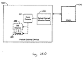
- a disordered breathing discrimination system comprising a disordered breathing detector configured to detect a disordered breathing event, a motion sensor configured to sense motion associated with respiratory effort of a patient during the disordered breathing event, and a disordered breathing classification processor coupled to the motion sensor and the disordered breathing detector.
- the disordered breathing classification processor may be configured to classify the disordered breathing event based on the respiratory effort motion, wherein at least one of the disordered breathing detector, the motion sensor, and the disordered breathing classification processor comprises an implantable component and the implantable and respiratory therapy devices are configured to operate cooperatively based on the classification of the disordered breathing event.
- Described herein are methods that provide for disordered breathing discrimination in a manner consistent with processes implemented by the above-described disordered breathing discrimination system.
- Described herein is an implantable device and a patient-external respiratory therapy device configured to operate cooperatively to adapt a therapy for disordered breathing. Described herein are methods that provide for cooperative adaptation of disordered breathing therapy.
- a sleep quality monitor coupled to at least one of an implantable device and a patient external respiratory therapy device.
- the sleep quality monitor is configured to collect sleep quality data.
- the sleep quality monitor may comprise a detector system configured to detect physiological and non-physiological conditions associated with sleep quality of a patient, and a data collection system coupled to the detector system and configured to collect sleep quality data based on the detected conditions.
- the implantable device and the patient external respiratory therapy device may be configured to operate cooperatively to collect or use the sleep quality data.
- Described herein are methods that provide for sleep quality monitoring in a manner consistent with processes implemented by the above-described sleep quality monitor.
- the respiration characterization system may comprising a respiration waveform sensor configured to acquire a respiration waveform, a respiration processor configured to determine one or more characteristics associated with the respiration, and a waveform generator coupled to the respiration waveform sensor and the respiration processor.
- the waveform generator may be configured to generate a marked respiration waveform comprising the respiration waveform and symbols indicating the one or more characteristics associated with the respiration, wherein the implantable device and the patient external respiratory device are configured to work cooperatively to generate or use the marked respiration waveform.
- Described herein are methods that provide for respiration characterization in a manner consistent with processes implemented by the above-described respiration characterization system.
- a gas therapy system comprising a sensor configured to sense concentration of a blood gas and a therapy controller coupled to the sensor and configured to adapt a gas therapy.
- a patient external respiratory therapy device may be coupled to the therapy controller and configured to deliver the gas therapy to a patient.
- An implantable device may be included that comprises at least one of the sensor and the controller.
- an implantable device and a patient external respiratory therapy device each comprising a sensing system configured to sense one or more physiological conditions, and further comprising a selection processor coupled to the implantable device and the patient external respiratory therapy device.
- the selection processor may be configured to select one or more of the devices to sense one or more physiological conditions.
- a diagnosis processor is coupled to the sensing systems of the implantable device and the patient external respiratory therapy device and configured to assess a presence of a medical disorder based on the one or more physiological conditions.
- an implantable device comprising a pulse generator configured to deliver cardiac pacing pulses to a patient's heart, and a respiratory therapy device configured to deliver an airway pressure to the patient.
- a control unit may be coupled to the pulse generator and configured to control the airway pressure delivered to the patient based on the delivery of the cardiac pacing pulses.
- Described herein are methods that provide for respiratory therapy control via a pulse generator in a manner consistent with processes implemented by the above-described system.
- a disordered breathing classification system includes a disordered breathing detector configured to detect disordered breathing in a patient.
- a motion sensor is configured to sense the patient's motion associated with respiratory effort during the disordered breathing event.
- a disordered breathing classification processor is coupled to the motion sensor and the disordered breathing detector. The disordered breathing classification processor is configured to classify the disordered breathing event based on motion associated with respiratory effort. At least one of the disordered breathing detector, the motion sensor, and the disordered breathing classification processor is at least in part implantable.
- Described herein are systems and methods for treating disordered breathing using cardiac pacing. Described herein are methods and systems for providing disordered breathing therapy. Described herein is a method for delivering disordered breathing therapy. Cardiac intervals between cardiac beats are obtained. A first indicated pacing interval is determined based at least one cardiac interval duration and a previous value of the first indicated pacing interval. Cardiac pacing to mitigate disordered breathing is provided based on the first indicated pacing interval.
- One method for characterizing respiration includes acquiring a respiration waveform.
- One of more characteristics associated with the patient's respiration are detected.
- a marked respiration waveform is generated using the respiration waveform and one or more symbols indicating the one or more characteristics associated with the patient respiration.
- At least one of acquiring the respiration waveform, detecting the one or more characteristics associated with the respiration, and generating the marked respiration waveform is performed at least in part implantably.
- the system includes a respiration waveform sensor configured to acquire a respiration waveform.
- a respiration processor is configured to determine one or more characteristics associated with the respiration.
- a waveform generator is coupled to the respiration waveform sensor and the respiration processor. The waveform generator is configured to generate a marked respiration waveform comprising the respiration waveform and symbols indicating the one or more characteristics associated with the respiration.
- At least one of the respiration waveform sensor, the respiration processor, and the waveform generator includes an implantable component.
- Described herein are methods and systems for organizing information related to sleep and/or events occurring during sleep.
- Described herein is an automated method for collecting and organizing information associated with sleep.
- the method includes detecting sleep and acquiring information associated with sleep.
- the acquired information is organized as a sleep logbook. At least one of detecting sleep, acquiring the information associated with sleep, and organizing the acquired information is performed at least in part implantably.
- Snoring information is useful in disordered breathing detection, verification, and/or prediction, such as for detecting or prediction of apnea events.
- Snoring detection is also useful independent of disordered breathing, to treat the snoring itself.
- Snoring may lead to insomnia, arousals from sleep, marital discord, and wake-time sleepiness.
- Snoring detection may also be used to treat the snoring, such as by modulating the pressure of a continuous positive airway pressure (CPAP) device to reduce the snoring, for example.
- CPAP continuous positive airway pressure
- Described herein are methods and systems for monitoring therapy delivered to a patient.
- Described herein is a method for implantably monitoring a patient-external respiration therapy delivered to the patient.
- the method includes sensing one or more conditions associated with patient-external breathing therapy.
- the patient-external respiration therapy is monitored by an implantable device based on the sensed conditions.
- a medical system includes a sensing system configured to sense conditions associated with a patient-external breathing therapy.
- the system also includes an implantable monitoring device, coupled to the sensing system.
- the implantable monitoring device is configured to monitor the patient-external breathing therapy based on the one or more sensed conditions.
- a method of controlling sleep disordered breathing therapy includes monitoring one or more patient conditions using a monitoring device having circuitry disposed within an implantable housing. Feedback information for controlling sleep disordered breathing therapy is developed based on the one or more monitored conditions. The feedback information is provided to a device delivering therapy to treat sleep disordered breathing.
- the housing of the therapy device is separate from the implantable housing of the monitoring device.
- a method of adjusting sleep disordered breathing therapy includes monitoring one or more patient conditions using a monitoring device having circuitry disposed within an implantable housing. Feedback information for controlling sleep disordered breathing therapy is developed based on the one or more monitored conditions. The feedback information is provided to a device delivering therapy to treat sleep disordered breathing. The housing of the therapy device is separate from the implantable housing of the monitoring device. The sleep disordered breathing therapy is adjusted using the feedback information.
- the medical system includes a monitoring unit having components disposed within an implantable housing.
- the monitoring unit is configured to monitor one or more patient conditions.
- a processor is coupled to the monitoring unit.
- the processor is configured to provide feedback information related to sleep disordered breathing therapy delivered to a patient based on the one or more monitored conditions.
- Components of a therapy device delivering the disordered breathing therapy are disposed within a therapy device housing.
- the therapy device housing is separate from the implantable housing of the monitoring device.
- the medical system includes a monitoring unit having components disposed within an implantable housing.
- the monitoring unit configured to monitor one or more patient conditions.
- the system also includes a therapy device having components disposed within a housing that is separate from the implantable housing of the monitoring device.
- the therapy device is configured to deliver sleep disordered breathing therapy.
- a processor is coupled to the monitoring unit and the therapy device.
- the processor is configured to provide feedback information related to the sleep disordered breathing therapy based on the one or more patient conditions.
- Embodiments may include systems and methods for detecting and/or diagnosing disorders, such as disordered breathing, a pulmonary, disorder, and/or a cardiac disorder, and providing therapy based on one or more conditions or parameters influenced by such diseases/disorders, such as blood gas concentrations, expired gas concentrations, or blood acid-base balance (i.e., hydrogen ion concentration).
- Methods of providing disordered breathing therapy may involve determining one or more parameters influence by disordered breathing, which may include one or more of blood gas concentration, expired respiratory gas concentration, or blood hydrogen ion concentration, also known as pH.
- Respiratory and cardiac therapies may be adjusted based on the one or more detected parameters.
- sensing the one or more sensed conditions may include sensing one or more of respiratory pressure, respiratory flow, and exhaled gas concentration.
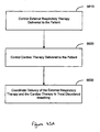
- a method for treating disordered breathing includes controlling a patient-external respiratory therapy delivered to a patient and controlling a cardiac therapy delivered to the patient.
- the patient-external respiratory therapy and the cardiac therapy are coordinated to treat the disordered breathing.
- a medical system includes a respiratory therapy controller configured to control an external respiratory therapy delivered to a patient and a cardiac therapy controller configured to deliver a cardiac therapy to the patient.
- the system also includes a processor, coupled to the respiratory therapy controller and the cardiac therapy controller. The processor is configured to coordinate delivery of the external respiratory therapy and the cardiac therapy to treat disordered breathing.
- Described herein are methods that involve adapting oxygen therapy delivered to a patient, wherein adapting the therapy involves comparing a blood oxygen level to a predetermined range and modifying the therapy if the blood oxygen level is beyond a predetermined range, such as by increasing oxygen gas pressure in response to the blood oxygen level falling below a threshold. Alternatively, or additionally, adding or increasing a vasodilator or a bronchodilator in response to the blood oxygen level falling below a threshold may also be performed.
- a therapy system includes a sensor unit configured to sense blood gas concentration.
- a therapy controller is coupled to the sensor unit and is configured to adapt a gas therapy.
- the system further includes a gas therapy delivery unit coupled to the therapy controller and configured to deliver the adapted gas therapy to the patient.
- At least one of the sensor unit and the controller includes an implantable component.
- each of the sensor unit and the therapy controller may have an implantable component.
- the sensor unit may be a component of an implantable cardiac therapy device or a component of a patient-external respiratory therapy device.
- the sensor unit may include a blood oxygen sensor and/or carbon dioxide sensor, and may be coupled to an implantable cardiac therapy device, directly or wirelessly.
- the sensor unit is coupled to the controller through the gas therapy delivery unit, which may deliver a vasodilating or a bronchodilator agent.
- a sensor may be configured to detect disordered breathing, and, in response to detecting disordered breathing, gas therapy may be modified (e.g., initiated, modified, terminated) to suppress the disordered breathing.
- gas therapy may be modified (e.g., initiated, modified, terminated) to suppress the disordered breathing.
- the type of disordered breathing may be discerned, such as discerning central apnea from obstructive apnea. If, for example, central apnea is detected, small amounts of carbon dioxide may be applied to the patient's air supply (e.g., via a positive airway pressure device) to mitigate the carbon dioxide instability that is leading to central apnea.
- Described herein are methods and systems for detecting medical disorders through synergistic use of one or more medical devices.
- Described herein is an automated method for detecting a presence of a medical disorder.
- one or more medical devices are selected to sense one or more conditions/parameters associated with a medical disorder.
- the conditions/ parameters are sensed using the selected medical devices and a presence of the medical disorder is assessed based on the sensed conditions/parameters.
- the one or more medical devices may be selected from a plurality of patient internal and patient-external medical devices. The selection may be made, for example, based on various sensing characteristics of the devices. The selection of medical devices used to sense the conditions/parameters may be altered for a variety of purposes.
- a system for assessing a disease presence involves a plurality of medical devices.
- Each medical device comprises a sensing system configured to sense one or more physiological conditions.
- a selection processor is coupled to the plurality of medical devices.
- the selection processor is configured to select one or more medical devices to sense one or more physiological conditions.
- a diagnosis processor coupled to the sensing systems of the plurality of medical devices and configured to assess a presence of a medical disorder based on the one or more physiological conditions.
- the medical devices may include one or more implantable device and/or one or more patient-external devices.
- the system may further include a therapy unit configured to delivering patient therapy based on the assessment of the presence of the medical disorder.
- the therapy unit may be a component of the medical devices and may be configured, for example, to deliver cardiac electrical therapy and/or an external respiratory therapy.
- Described herein are methods and systems for matching intrathoracic pressure with cardiac cycle phase.
- Described herein is a method for delivering airway pressure to a patient. The method includes determining the cardiac cycle phase and controlling the airway pressure based on the cardiac cycle phase. Controlling the airway pressure is performed at least in part implantably.
- a therapy control system includes a detector system configured to determine cardiac cycle phase and control unit coupled to the detector system.
- the control unit is configured to control airway pressure based on the cardiac cycle phase.
- the control unit includes at least one implantable component.
- Methods, devices, and systems implementing a coordinated approach to patient monitoring, diagnosis, and /or therapy in accordance with the present invention may incorporate one or more of the features, structures, methods, or combinations thereof described herein below.
- a medical system may be implemented to include one or more of the features and/or processes described below. It is intended that such a method, device, or system need not include all of the features and functions described herein, but may be implemented to include one or more selected features and functions that provide useful structures and/or functionality.
- Disorders and diseases affecting the interdependent physiological systems of the human body may be more effectively diagnosed and treated using a coordinated approach.
- Various embodiments of the invention are implemented using medical systems employing one or a number of patient-external and/or patient-internal medical devices. Medical devices may communicate or otherwise operate in concert or in a stand-alone manner to provide more comprehensive patient monitoring, diagnosis, and therapy.
- condition denotes an attribute that may be sensed and/or measured based on a signal generated by a sensor or other input device of a respiratory therapy device or another medical device.
- symptom and “physiological change” refer to a manifestation of a medical disease or disorder. Symptoms and/or physiological changes may be detectable based on a sensed presence of one or more physiological conditions and/or measured values associated with the one or more sensed physiological conditions.
- disease and/or “disorder” are used to refer to a medical dysfunction that is characterizable by a collection of symptoms or physiological changes.
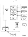
- FIG. 1A is a block diagram of a medical system 100 that may be used to implement coordinated patient monitoring, diagnosis, and/or therapy in accordance with embodiments of the invention.
- the medical system 100 may include, for example, one or more patient-internal medical devices 110 and one or more patient-external medical devices 120.
- Each of the patient-internal 110 and patient-external 120 medical devices may include one or more of a patient monitoring unit 112, 153, a diagnostics unit 114, 154, and/or a therapy unit 116, 155.
- the patient-internal medical device 110 is typically a fully or partially implantable device that performs monitoring, diagnosis, and/or therapy functions.
- the patient-external medical device 120 performs monitoring, diagnosis and/or therapy functions external to the patient (i.e., not invasively implanted within the patient's body).
- the patient-external medical device 120 may be positioned on the patient, near the patient, or in any location external to the patient. It is understood that a portion of a patient-external medical device 120 may be positioned within an orifice of the body, such as the nasal cavity or mouth, yet can be considered external to the patient (e.g., mouth pieces/appliances, tubes/appliances for nostrils, or temperature sensors positioned in the ear canal).
- the patient-internal and patient-external medical devices 110, 120 may be coupled to one or more sensors 141, 142, 145, 146, patient input devices 143, 147 and/or other information acquisition devices 144, 148.
- the sensors 141, 142, 145, 146, patient input devices 144, 147, and/or other information acquisition devices 144, 148 may be employed to detect conditions relevant to the monitoring, diagnostic, and/or therapeutic functions of the patient-internal and patient-external medical devices 110, 120.
- the medical devices 110, 120 may each be coupled to one or more patient-internal sensors 141, 145 that are fully or partially implantable within the patient.
- the medical devices 110, 120 may also be coupled to patient-external sensors positioned on, near, or in a remote location with respect to the patient.
- the patient-internal and patient-external sensors are used to sense conditions, such as physiological or environmental conditions, that affect the patient.
- the patient-internal sensors 141 may be coupled to the patient-internal medical device 110 through internal leads.
- an internal endocardial lead system used to couple cardiac electrodes to an implantable pacemaker or other cardiac rhythm management device.
- One or more patient-internal sensors 141 may be equipped with transceiver circuitry to support wireless communications between the one or more patient-internal sensors 141 and the patient-internal medical device 110 and/or the patient-external medical device 120.
- the patient-external sensors 142 may be coupled to the patient-internal medical device 110 and/or the patient-external medical device 120 through leads or through wireless connections.
- Patient-external sensors 142 preferably communicate with the patient-internal medical device 110 wirelessly.
- Patient-external sensors 146 may be coupled to the patient-external medical device 120 through leads or through a wireless link.
- the medical devices 110, 120 may be coupled to one or more patient-input devices 143, 147.
- the patient-input devices are used to allow the patient to manually transfer information to the medical devices 110, 120.
- the patient input devices 143, 147 may be particularly useful for inputting information concerning patient perceptions, such as how well the patient feels, and information such as patient smoking, drug use, or other activities that are not automatically sensed or detected by the medical devices 110, 120.
- the medical devices 110, 120 may be connected to one or more information systems 144, 148, for example, a database that stores information useful in connection with the monitoring, diagnostic, or therapy functions of the medical devices 110, 120.
- one or more of the medical devices 110, 120 may be coupled through a network to a information system server that provides information about environmental conditions affecting the patient, e.g., the pollution index for the patient's location.
- the patient-internal medical device 110 and the patient-external medical device 120 may communicate through a wireless link between the medical devices 110, 120.
- the patient-internal and patient-external devices 110, 120 may be coupled through a short-range radio link, such as Bluetooth or a proprietary wireless link.
- the communications link may facilitate uni-directional or bi-directional communication between the patient-internal 110 and patient-external 120 medical devices or particular units of medical devices 110, 120.
- Data and/or control signals may be transmitted between the patient-internal 110 and patient-external 120 medical devices to coordinate the functions of the medical devices 110, 120.
- the patient-internal and patient-external medical devices 110, 120 may be used within the structure of an advanced patient management system.
- Advanced patient management systems involve a system of medical devices that are accessible through various communications technologies.
- patient data may be downloaded from one or more of the medical devices periodically or on command, and stored at a patient information server.
- the physician and/or the patient may communicate with the medical devices and the patient information server, for example, to acquire patient data or to initiate, terminate or modify therapy.
- the patient-internal medical device 110 and the patient-external medical device 120 may be coupled through a wireless or wired communications link to a patient information server that is part of an advanced patient management system 170.
- the APM patient information server 170 may be used to download and store data collected by the patient-internal and patient-external medical devices 110, 120.
- the data stored on the APM patient information server 170 may be accessible by the patient and the patient's physician through terminals 150, e.g., remote computers located in the patient's home or the physician's office.
- the APM patient information server 170 may be used to communicate to one or more of the patient-internal and patient-external medical devices 110,120 to effect remote control of the monitoring, diagnosis, and/or therapy functions of the medical devices 110, 120.
- the patient's physician may access patient data transmitted from the medical devices 110, 120 to the APM patient information server 170. After evaluation of the patient data, the patient's physician may communicate with one or more of the patient-internal or patient-external devices 110, 120 through the APM system 170 to initiate, terminate, or modify the monitoring, diagnostic, and/or therapy functions of the patient-internal and/or patient-external medical systems 110, 120.
- the patient-internal and patient-external medical devices 110, 120 may not communicate directly, but may communicate indirectly through the APM system 170.
- the APM system 170 may operate as an intermediary between two or more of the medical devices 110, 120.
- data and/or control information may be transferred from one of the medical devices 110, 120 to the APM system 170.
- the APM system 170 may transfer the data and/or control information to another of the medical devices 110, 120.
- the APM system may communicate directly with the patient-internal and/or patient-external medical devices 110, 120.
- the advanced patient management (APM) information server 170 may be used to download and store data collected by the patient-internal and patient-external medical devices 110, 120.
- FIGS 1B —1D illustrate various medical procedures that may be implemented by a coordinated medical system in accordance with embodiments of the invention.
- Each of the circles 180 illustrated in Figures 1B —1D represents an individual medical procedure providing a specific monitoring, diagnosis or therapeutic function or set of functions.
- Each individual medical procedure may be implemented as a stand-alone system.
- Two or more of the individual medical procedures 180 may be used in combination to provide more comprehensive patient monitoring, diagnosis and/or therapy.
- One or more functions of two or more individual medical procedures 180 may be used in combination to enhance patient monitoring, diagnosis and/or therapy.
- Coordinated medical procedures may involve cooperative operation of two or more of the individual processes 180. Coordinated medical procedures may also involve cooperative operation of one or more functions of two or more of the individual processes 180.
- Coordinated use of two or more medical procedures typically involves transfer of some form of information, such as data and/or control signals, that is used by, or influences the behavior of the medical procedures or devices implementing such medical procedures.
- the transfer of information may implicate one of the medical procedures, some of the medical procedures, or all of the medical procedures.
- the transfer of information may implicate other processes that interact with one or more medical procedures, such as processes implemented by a patient-external processing system.
- the transfer of information may be unidirectional or bi-directional with respect to medical procedures and/or other processes.
- Embodiments of the invention involve individual systems for performing the various medical procedures 180.
- Each of the procedures 180 may be implemented as a stand alone system or in combination with other individual medical procedures or systems 180, such as those described in Figures 1B —1D.
- the coordinated system may include, for example, an implantable cardiac device 181 and a patient-external respiratory therapy device 184.
- the system may further include an external processor 183 providing a coordination function.
- a communication channel couples the implantable device 181 and the respiratory therapy device 184.
- the implantable 181 and respiratory therapy devices 184 operate cooperatively via the communication channel to provide one or more of patient monitoring, diagnosis, and therapy.
- one or both of the devices 110, 120 of the medical system 100 may include a monitoring unit 112, 153, a diagnostics unit 114, 154, and a therapy unit 116, 155.
- a monitoring unit 112, 153, a diagnostics unit 114, 154, and a therapy unit 116, 155 may be used alone or in cooperation with other components of the medical system 100 to implement the various medical procedures 180.
- Monitoring circuitry 112, 153 of one or both devices 110, 120 may include detection and/or monitoring functionality that may be employed to implement one or more processes of the medical procedures 180 indicated in Figure 1B —1D involving monitoring and/or detection.
- monitoring circuitry 112, 153 may be used in connection with on or more of sleep detection 54, sleep quality monitoring 58, sleep stage detection 60, marked respiratory waveform generation 105, medical event/respiratory event logbook generation 106, sleep logbook generation 184, monitoring of respiratory therapy 122, posture detection 131, cardiac event detection via the respiratory therapy device 133 snoring detection 139, and autonomic arousal detection 106.
- Diagnosis circuitry incorporated in one or both devices 110, 120 may be used to implement processes of the one or more of the medical procedures 180 indicated in Figures 1B —1D that involve assessing a presence of diseases or disorders.
- one or both diagnosis units 114, 153 maybe used in connection with one or more of pulmonary disease detection 136, disordered breathing detection 54, central and obstructive disordered breathing detection 124, detection of movement disorders 141, disease detection based on use of diurnal data 129, use of electromyogram for disease diagnosis 127, diagnosis based on blood chemistry/blood gas 130, and disease detection by synergistic use of respiratory therapy and cardiac devices 126.
- Therapy delivery of therapy control circuitry incorporated in one or both devices 110, 120 may be used to implement processes of the one or more of the medical procedures 180 indicated in Figures 1B —1D that involve delivery or control of therapy
- one or both therapy units 116, 155 maybe used in connection with one or more of adaptive cardiac therapy for disordered breathing 59, overdrive pacing for disordered breathing 128, therapy based on prediction of disordered breathing 103, respiratory therapy based on feedback from an implanted monitor 123, modification of therapy using detected cardiopulmonary conditions 137, automatic activation of therapy based on brain waves 132, modulation of external gas therapy 135, disordered breathing therapy using a combination of cardiac and respiratory therapies 138, modulation of respiration therapy based on cardiac cycle phase 141, modulation of cardiac pacing based on respiration cycle 197.
- FIGS. 2A and 2B provide examples of a coordinated monitoring, diagnosis and/or therapeutic system 200 in accordance with embodiments of the invention.
- the system 200 employs medical device 210 that may be fully or partially implantable.
- the medical device 210 performs at least one cardiac function.
- the implantable cardiac device 210 may be coupled to an array of data acquisition devices 212, including patient-internal sensors, patient-external sensors, patient input devices, and/or other information systems for sensing, detecting and/or measuring conditions or parameters affecting the patient and useful for the monitoring, diagnostic, and/or therapeutic functions of the coordinated system 200.
- the system 200 employs a respiratory therapy device 220.
- the respiratory therapy device may be positioned on the patient, near the patient, or in any location external to the patient. It is understood that a portion of a respiratory therapy device 220 may be positioned within an orifice of the body, such as the nasal cavity or mouth, yet can be considered external to the patient (e.g., mouth pieces/appliances, tubes/appliances for nostrils, or temperature sensors positioned in the ear canal).
- the respiratory therapy device 220 may be coupled to an array of data acquisition devices 222, including patient-internal sensors, patient-external sensors, patient input devices, and/or other information systems for sensing, detecting and/or measuring conditions or parameters affecting the patient and useful for the monitoring, diagnostic, and/or therapeutic functions of the coordinated system 200.
- data acquisition devices 222 including patient-internal sensors, patient-external sensors, patient input devices, and/or other information systems for sensing, detecting and/or measuring conditions or parameters affecting the patient and useful for the monitoring, diagnostic, and/or therapeutic functions of the coordinated system 200.
- Patient conditions or parameters may include both physiological and non-physiological contextual conditions affecting the patient.
- Physiological conditions may include a broad category of conditions associated with the internal functioning of the patient's physiological systems, including the cardiovascular, respiratory, nervous, muscle and other systems. Examples of physiological conditions include blood chemistry, patient posture, patient activity, respiration quality, sleep quality, among others.
- Contextual conditions generally encompass non-physiological, patient-external or background conditions.
- Contextual conditions may be broadly defined to include, for example, present environmental conditions, such as patient location, ambient temperature, humidity, air pollution index.
- Contextual conditions may also include historical/background conditions relating to the patient, including the patient's normal sleep time and the patient's medical history, for example.
- Table 1 provides a representative set of patient conditions that may be used in connection with a coordinated approach to patient monitoring, diagnostics, and/or therapy in accordance with embodiments of the invention. Table 1 also provides illustrative sensing methods that may be employed to sense the conditions. It will be appreciated that patient conditions and detection methods other than those listed in Table 1 may be used in connection with patient monitoring, diagnosis, and/or therapy and are considered to be within the scope of the invention.
- Table 1 Condition Type Condition Sensor type or Detection method Physiological Cardiovascular System Heart rate Heart rate variability QT interval EGM, ECG Ventricular filling pressure Intracardiac pressure sensor Blood pressure Blood pressure sensor Respiratory System Snoring Accelerometer Microphone Respiration pattern (Tidal volume Minute ventilation Respiratory rate) Transthoracic impedance sensor (AC) Patency of upper airway Intrathoracic impedance sensor Pulmonary congestion Transthoracic impedance sensor (DC) Nervous System Sympathetic nerve activity Muscle sympathetic nerve Activity sensor Brain activity EEG Blood Chemistry CO2 saturation O2 saturation Blood alcohol content Adrenalin Brain Natriuretic Peptide (BNP) C-Reactive Protein Drug/Medication/Tobacco use Blood analysis Muscle System Muscle atonia EMG Eye movement EOG Patient activity Accelerometer, MV, etc.
- EGM ECG Ventricular filling pressure
- Intracardiac pressure sensor Blood pressure Blood pressure sensor Respiratory System Snoring Accelerometer Microphone Respiration pattern (Tidal volume Minute ventilation Respir
- One or both of the medical devices 210, 220 of Figure 2A may include a monitoring unit, as previously described in connection with Figure 1A , that processes signals from one or more of the sensors or other data acquisition devices.
- the monitoring unit may include processes to detect the occurrence of various events, including, for example, normal and/or abnormal physiological system events or condition, cardiovascular system events, a respiratory system events, muscle system events, nervous system event, and/or a sleep-related events. Other types of events may also be detected.
- detection of a cardiovascular system event may involve detection of detect abnormal or unusual events of the cardiovascular system such as ventricular tachycardia or fibrillation.
- the detection of a cardiovascular system event may alternatively involve detection of normal cardiac beats or other events or conditions associated with the usual functioning of the heart.
- Respiratory event detection may involve events or conditions associated with various respiratory system disorders, such as a disordered breathing event or a pulmonary congestion condition. Respiratory system event/condition detection may also be used to detect the inspiratory and expiratory phases of normal respiration cycles, for example.
- Muscle system event/condition detection may involve detection of abnormal limb movements, such as those associated with periodic limb movement disorder (PLMD), for example. Muscle system event/condition detection may further be used to detect normal or abnormal conditions, such as normal muscle atonia associated with REM sleep or abnormal muscle tone of the upper airway associated with obstructive sleep apnea events. The muscle system event/condition detection may also be used, for example, to detect the level of patient activity. Patient activity information may be useful, for example, in assessing the overall activity level of the patient, or determining if the patient is asleep.
- PLMD periodic limb movement disorder
- Detection of nervous system events may comprise, for example, detection arousals for sleep, or detection of brain wave activity events.
- Sleep-related events such as sleep onset, sleep offset, sleep stages, arousals from sleep disordered breathing events, and nocturnal movements may be monitored in connecting with sleep quality assessment.
- Information related to parameter or conditions affecting the patient may be stored in memory.
- the stored data may be transmitted to another component of the medical devices 210, 220 or to a separate device for storage, further processing, trending, analysis and/or display, for example.
- the stored data can be downloaded to a separate device periodically or on command.
- the stored data may be presented to the patient's health care professional on a real-time basis, or as a long-term, e.g., month long or year long, trend of daily measurements.
- One or both of the devices 210, 220 may include the capability of assessing disease presence and/or diagnosing various diseases or disorders.
- the diagnostics capability of the medical devices 210, 220 may rely on information acquired and stored in memory over a period of time. Diagnostics or assessments of disease presence may involve evaluation of events or conditions detected by the monitoring/detection components of the devices 210, 220.
- One or both medical devices 210, 220 may include the ability to deliver or control the delivery of therapy to a patient.
- the cardiac device 210 may deliver cardiac electrical stimulation therapy using a cardiac pulse generator and electrical stimulation electrodes.
- the respiratory therapy device 220 may delivery any of a variety of respiration therapies, including, for example, continuous positive airway pressure (CPAP), bi-level positive airway pressure (bi-PAP), proportional positive airway pressure (PPAP), auto-titrating positive airway pressure, ventilation, gas, pharmacological agent, or oxygen therapies, among others.
- CPAP continuous positive airway pressure
- bi-PAP bi-level positive airway pressure
- PPAP proportional positive airway pressure
- auto-titrating positive airway pressure ventilation, gas, pharmacological agent, or oxygen therapies, among others.
- One of the devices 210, 220 may partially or fully control the therapy delivered by the other device 220, 210.
- the cardiac device 210 may control or aid in the control of therapy delivered by the respiratory device 220.
- the respiratory device 220 may control or aid in the control of therapy delivered by the cardiac device 210.
- One or both of the medical devices 210, 220 may fully or partially control other therapy delivery devices or receive input from other sensors.
- one or both of the medical devices 210, 220 may be used to control a drug therapy device, such as a drug pump, a controllable nebulizer, and/or electrically activated drug patch.
- a drug therapy device such as a drug pump, a controllable nebulizer, and/or electrically activated drug patch.
- one or both of the medical devices 210, 220 may be used to control a nerve stimulation or muscle stimulation therapy device, such as a hypoglossal or phrenic nerve stimulation device.
- the medical system 200 includes a uni-directional or bidirectional communications channel 241 between the medical devices 210, 220.
- the communications channel 241 facilitates the cooperation between the medical devices 210, 220.
- the communications channel 241 may be implemented as a wireless link between the cardiac device 210 and the respiratory therapy device 220.
- the wireless communication channel 241 coupling the medical devices 210, 220 may utilize a variety of wireless protocols, including, for example, Bluetooth, IEEE 802.11, and/or a proprietary wireless protocol.
- the medical system 201 includes an external processor 230.
- the external processor 230 may comprise, for example, an advanced patient management system, as previously described.
- the external processor 230 may acquire patient conditions or parameters 232, store patient information, provide monitoring and/or diagnostic functionality 231, control therapy 231 delivered by the cardiac and/or respiratory devices 210, 220 and/or other therapy devices.
- the external processor may be coupled to one or both of the cardiac and respiratory devices 210, 220 through wireless or wired communications channels 243, 242.
- the cardiac and respiratory devices 210, 220 may not communicate directly, but may communicate indirectly via the external processor 230.
- FIG. 3 illustrates a respiratory therapy device 300 in accordance with embodiments of the invention.
- Respiratory therapy such as gas therapy, oxygen therapy, CO2 therapy, positive airway pressure therapy, or other therapies provided to a patient through the pulmonary system, may mitigate a patient's suffering from a number of respiratory disorders.
- Some lung diseases such as emphysema, sarcoidosis, and chronic obstructive pulmonary disorder, reduce lung function to the extent that supplemental oxygen is needed to continue normal bodily functions.
- oxygen therapy allows the patients to get the oxygen they need, helps them be more active, and may also prevent or treat heart failure. All types of respiratory therapy devices are referred to generically herein as xPAP devices.
- the respiratory therapy device 300 may include, for example, any of the positive airway pressure devices, including CPAP, bi-level positive airway pressure (bi-PAP), proportional positive airway pressure (PPAP), and/or autotitration positive airway pressure devices, for example.
- Continuous positive airway pressure (CPAP) devices deliver a set air pressure to the patient.
- the pressure level for the individual patient may be determined during a titration study. Such a study may take place in a sleep lab, and involves determination of the optimum airway pressure by a sleep physician or other professional.
- the CPAP device pressure control is set to the determined level. When the patient uses the CPAP device, a substantially constant airway pressure level is maintained by the device.
- Autotitration PAP devices are similar to CPAP devices, however, the pressure controller for autotitration devices automatically determines the air pressure for the patient. Instead of maintaining a constant pressure, the autotitration PAP device evaluates sensor signals and the changing needs of the patient to deliver a variable positive airway pressure. Autotitration PAP and CPAP are often used to treat sleep disordered breathing, for example.
- Bi-level positive airway pressure (bi-PAP) devices provide two levels of positive airway pressure. A higher pressure is maintained while the patient inhales. The device switches to a lower pressure during expiration. Bi-PAP devices are used to treat a variety of respiratory dysfunctions, including chronic obstructive pulmonary disease (COPD), respiratory insufficiency, and ALS or Lou Gehrig's disease, among others.
- COPD chronic obstructive pulmonary disease
- COPD chronic obstructive pulmonary disease
- ALS Lou Gehrig's disease
- Respiratory therapy may be provided by a servo ventilation device.
- Servo ventilation devices provide airway pressure dependent on the respiration cycle stage.
- a servo ventilation device provides positive pressure on inhalation and negative pressure on exhalation.
- the respiration therapy control unit 340 illustrated in this example as a positive airway device, includes a flow generator 342 that pulls in air through a filter.
- the flow generator 342 is controlled by the pressure control circuitry 344 to deliver an appropriate air pressure to the patient.
- the mask 348 may be a nasal mask covering only the patient's nose. In another example, the mask 348 covers the patient's nose and mouth.
- the respiratory device 300 includes a communications unit 380 for communicating with one or more separate devices, including patient-external and/or patient-internal monitoring, diagnostic and/or therapeutic devices.
- the respiratory therapy device 300 may receive information from one or more data acquisition devices 350, e.g., sensors, patient input devices, and/or other information systems. The acquired information may be used to implement one or more monitoring, diagnostic and/or therapeutic functions 360 of the respiratory therapy device 300.
- a monitoring processor 360 may be used to store information related to one or more physiological or nonphysiological parameters acquired over a period of time.
- a diagnostics unit may assess the presence of a disease or disorder based on information acquired through use of the data acquisition devices and/or received via the communications channel 370 from a separate device.
- therapy delivered by the respiratory therapy device 300 may be controlled by a therapy processor 360.
- the therapy processor 360 may control therapy delivered by remote device coupled to the respiratory therapy device 300 via the communications channel 370.
- FIG. 4A is a partial view of an implantable cardiac device that may include circuitry for implementing coordinated monitoring, diagnosis and/or therapy in accordance with embodiments of the invention.
- the implantable device comprises a cardiac rhythm management device (CRM) 400 including an implantable electrical stimulation generator 405 electrically and physically coupled to an intracardiac lead system 410. Portions of the intracardiac lead system 410 are inserted into the patient's heart 490.
- the intracardiac lead system 410 includes one or more electrodes configured to sense electrical cardiac activity of the heart, deliver electrical stimulation to the heart, sense the patient's transthoracic impedance, and/or sense other physiological parameters, e,g, cardiac chamber pressure or temperature. Portions of the housing 401 of the pulse generator 405 may optionally serve as a can electrode.
- Communications circuitry is disposed within the housing 401 for facilitating communication between the electrical stimulation generator 405 and remote devices having wireless communication functionality, such as a portable or bed-side communication station, patient-carried/worn communication station, or external programmer, for example.
- the wireless communications circuitry can also facilitate unidirectional or bidirectional communication with one or more implanted, external, cutaneous, or subcutaneous physiologic or non-physiologic sensors, patient-input devices and/or other information systems.
- the housing 401 of the electrical stimulation generator 405 may optionally incorporate various sensors, including, for example, a motion sensor that may be programmed to sense various conditions.
- the motion sensor may be optionally configured to sense snoring, patient activity level, and/or chest wall movements associated with respiratory effort, for example.
- the motion detector may be implemented as an accelerometer positioned in or on the housing 401 of the electrical stimulation generator 405. If the motion sensor is implemented as an accelerometer, the motion sensor may also provide respiratory information, e.g. rales, coughing, and cardiac information, e.g. S1-S4 heart sounds, murmurs, and/or other acoustic information.
- the lead system 410 of the CRM 400 may incorporate one or more electrodes used to sense transthoracic impedance.
- Transthoracic impedance sensing may be used to acquire the patient's respiration waveform, or other respiration-related information.
- Transthoracic impedance may be sensed using one or more intracardiac electrodes 441, 442, 451-455, 463 positioned in one or more chambers of the heart 490.
- the intracardiac electrodes 441, 442, 451-455, 463 may be coupled to impedance drive/sense circuitry positioned within the housing of the electrical stimulation generator 405.
- impedance drive/sense circuitry disposed within the housing 401 generates a current that flows through the tissue between an impedance drive electrode 451 and a can electrode on the housing 401 of the electrical stimulation generator 405.
- the voltage at an impedance sense electrode 452 relative to the can electrode changes as the patient's transthoracic impedance changes.
- the voltage signal developed between the impedance sense electrode 452 and the can electrode is detected by the impedance sense circuitry disposed within the housing 401 of the electrical stimulation generator 405.
- Other locations and/or combinations of impedance sense and drive electrodes are also possible.
- the voltage signal developed at the impedance sense electrode 452, illustrated in Figure 4A is proportional to the patient's transthoracic impedance and represents the patient's respiration waveform.
- the transthoracic impedance increases during respiratory inspiration and decreases during respiratory expiration.
- the peak-to-peak transition of the transthoracic impedance is proportional to the amount of air moved in one breath, denoted the tidal volume.
- the amount of air moved per minute is denoted the minute ventilation.
- the lead system 410 may include one or more cardiac pace/sense electrodes 451—455 positioned in, on, or about one or more heart chambers for sensing electrical signals from the patient's heart 490 and/or delivering pacing pulses to the heart 490.
- the intracardiac sense/pace electrodes 451—455, such as those illustrated in Figure 4A may be used to sense and/or pace one or more chambers of the heart, including the left ventricle, the right ventricle, the left atrium and/or the right atrium.
- the lead system 410 may include one or more defibrillation electrodes 441, 442 for delivering defibrillation/cardioversion shocks to the heart 490.
- the housing 401 of the electrical stimulation generator 405 may include circuitry for detecting cardiac arrhythmias and/or for controlling pacing and/or defibrillation therapy in the form of electrical stimulation pulses or shocks delivered to the heart through the lead system 410. Also disposed within the housing 401 may be various communications circuitry and monitoring, diagnostic, and/or therapy control circuitry that may be used to effect coordinated monitoring, diagnosis and/or therapy in accordance with embodiments of the invention.
- an implantable transthoracic cardiac sensing and/or stimulation (ITCS) device may be implemented to detect/monitor normal and abnormal cardiac and/or respiratory activity, and may be configured to deliver an appropriate therapy in response to abnormal activity or conditions.
- An ITCS device 500 of the present invention may be configured for monitoring, diagnosing, and/or treating cardiac and disordered breathing events/conditions.
- An ITCS device 500 is typically implemented to sense activity of both the cardiac system and the respiratory system. Using appropriate sensors, the ITCS device 500 may be implemented to detect and monitor a variety of disordered breathing conditions, including sleep and non-sleep related disordered breathing conditions.
- An ITCS device 500 may further be implemented to detect sleep, and may further be implemented to detect stages of patient sleep.
- An ITCS device 500 so implemented may be configured to perform a variety of sensing, monitoring, diagnosing, and/or therapy control/coordination functions, including those described herein and in the references respectively incorporated herein.
- FIG. 5A is a block diagram illustrating various components of an ITCS device 500 that provides for disordered breathing detection and/or treatment in accordance with embodiments of the present invention.
- cardiac activity and disordered breathing e.g., sleep disordered breathing and wakeful disordered breathing
- An ITCS device 500 may be implanted under the skin in the chest region of a patient.
- the ITCS device 500 may, for example, be implanted subcutaneously such that all or selected elements of the device are positioned on the patient's front, back, side, or other body locations suitable for sensing cardiac activity and delivering cardiac stimulation therapy.
- elements of the ITCS device 500 may be located at several different body locations, such as in the chest, abdominal, or subclavian region with electrode elements respectively positioned at different regions near, around, or on the heart.
- the primary housing (e.g., the active or non-active can) 502 of the ITCS device 500 may be configured for positioning outside of the rib cage at an intercostal or subcostal location, within the abdomen, or in the upper chest region (e.g., subclavian location, such as above the third rib).
- one or more electrodes may be located on the primary housing 502 and/or at other locations (e.g., electrode 504) about, but not in direct contact with the heart, great vessels or coronary vasculature.
- a pulse generator and a cardiac stimulation controller are disposed in the primary housing 502.
- the cardiac stimulator controller determines and coordinates appropriate cardiac and/or respiratory therapy to be delivered to a patient, and the pulse generator produces the appropriate energy waveforms associated with a selected therapy.
- a cardiac activity detector configured to detect normal and abnormal (e.g., arrhythmic) cardiac activity.
- one or more subcutaneous electrode subsystems or electrode arrays 504 may be used to sense cardiac activity and deliver cardiac stimulation energy in an ITCS device 500 configuration employing an active can or a configuration employing a non-active can. Electrodes (e.g., electrode 504) may be situated at anterior and/or posterior locations relative to the heart.
- the ITCS device 500 depicted in Figure 5A may be configured in a manner described herein or may have other configurations.
- An ITCS device 500 of the present invention may be implemented to include one or more of cardiac and/or respiratory detection/monitoring circuitry (e.g., for cardiac activity, breathing patterns such as from transthoracic impedance signals, heart sounds, blood gas/chemistry such as oxygen saturation and/or pH), cardiac and respiratory diagnostics circuitry, and cardiac and respiratory therapy circuitry.
- An ITCS device 500 of the present invention may be implemented to provide for upgradeability in terms of functionality and/or configuration.
- an ITCS device 500 may be implemented as an upgradeable or reconfigurable cardiac/respiratory monitor or stimulation device.
- An ITCS device 500 in accordance with embodiments of the present invention provides for patient breathing monitoring and disordered breathing detection and/or prediction. Such embodiments may further provide treatment for detected or predicted disordered breathing events or conditions, as determined by a therapy controller or in response to an externally generated command signal (such as received from an advanced patient management system or programmer). Detection and treatment of disordered breathing and/or respiratory conditions may be facilitated by use of an ITCS device 500 having appropriate sensing/detection/therapy delivery capabilities, or by cooperative use of an ITCS device 500 and an external programmer or an advanced patient management system via a communications interface.
- the ITCS device 500 includes a housing 502 within which various cardiac and respiratory sensing, detection, processing, and energy delivery circuitry may be housed.
- Communications circuitry is disposed within the housing 502 for facilitating communication between the ITCS device 500 and an external communication device, such as a portable or bed-side communication station, patient-carried/worn communication station, or external programmer, for example.
- the communications circuitry may also facilitate unidirectional or bidirectional communication with one or more external, cutaneous, or subcutaneous physiologic or non-physiologic sensors.
- the housing 502 is typically configured to include one or more electrodes (e.g., can electrode and/or indifferent electrode). Although the housing 502 is typically configured as an active can, it is appreciated that a non-active can configuration may be implemented, in which case at least two electrodes spaced apart from the housing 502 are employed.
- a subcutaneous electrode 504 may be positioned under the skin in the chest region and situated distal from the housing 502.
- the subcutaneous and, if applicable, housing electrode(s) may be positioned about the heart at various locations and orientations, such as at various anterior and/or posterior locations relative to the heart.
- the subcutaneous electrode 504 is coupled to circuitry within the housing 502 via a lead assembly 506.
- One or more conductors e.g., coils or cables
- the lead assembly 506 are provided within the lead assembly 506 and electrically couple the subcutaneous electrode 504 with circuitry in the housing 502.
- One or more sense, sense/pace or defibrillation electrodes may be situated on the elongated structure of the electrode support, the housing 502, and/or the distal electrode assembly (shown as subcutaneous electrode 504 in the configuration shown in Figure 5A ).
- the lead assembly 506 is generally flexible and has a construction similar to conventional implantable, medical electrical leads (e.g., defibrillation leads or combined defibrillation/pacing leads).
- the lead assembly 506 is constructed to be somewhat flexible, yet has an elastic, spring, or mechanical memory that retains a desired configuration after being shaped or manipulated by a clinician.
- the lead assembly 506 may incorporate a gooseneck or braid system that may be distorted under manual force to take on a desired shape. In this manner, the lead assembly 506 may be shape-fit to accommodate the unique anatomical configuration of a given patient, and generally retains a customized shape after implantation. Shaping of the lead assembly 506 according to this configuration may occur prior to, and during, ITCS device 500 implantation.
- the lead assembly 506 includes an electrode support assembly, such as an elongated structure that positionally stabilizes the subcutaneous electrode 504 with respect to the housing 502.
- an electrode support assembly such as an elongated structure that positionally stabilizes the subcutaneous electrode 504 with respect to the housing 502.
- the rigidity of the elongated structure maintains a desired spacing between the subcutaneous electrode 504 and the housing 502, and a desired orientation of the subcutaneous electrode104/housing 502 relative to the patient's heart.
- the elongated structure may be formed from a structural plastic, composite or metallic material, and includes, or is covered by, a biocompatible material. Appropriate electrical isolation between the housing 502 and subcutaneous electrode 504 is provided in cases where the elongated structure is formed from an electrically conductive material, such as metal.
- the electrode support assembly and the housing 502 define a unitary structure (e.g., a single housing/unit).
- the electronic components and electrode conductors/connectors are disposed within or on the unitary ITCS device 500 housing/electrode support assembly. At least two electrodes are supported on the unitary structure near opposing ends of the housing/electrode support assembly.
- the unitary structure may have an arcuate or angled shape, for example.
- the electrode support assembly defines a physically separable unit relative to the housing 502.
- the electrode support assembly includes mechanical and electrical couplings that facilitate mating engagement with corresponding mechanical and electrical couplings of the housing 502.
- a header block arrangement may be configured to include both electrical and mechanical couplings that provide for mechanical and electrical connections between the electrode support assembly and housing 502.
- the header block arrangement may be provided on the housing 502 or the electrode support assembly.
- a mechanical/electrical coupler may be used to establish mechanical and electrical connections between the electrode support assembly and housing 502.
- a variety of different electrode support assemblies of varying shapes, sizes, and electrode configurations may be made available for physically and electrically connecting to a standard ITCS device 500 housing 502.
- the electrodes and the lead assembly 506 may be configured to assume a variety of shapes.
- the lead assembly 506 may have a wedge, chevron, flattened oval, or a ribbon shape
- the subcutaneous electrode 504 may include a number of spaced electrodes, such as an array or band of electrodes.
- two or more subcutaneous electrodes 504 may be mounted to multiple electrode support assemblies 506 to achieve a desired spaced relationship amongst subcutaneous electrodes 504.
- FIG. 5B is a block diagram depicting various components of an ITCS device 500 in accordance with one configuration.
- the ITCS device 500 incorporates a processor-based control system 505 which includes a micro-processor 526 coupled to appropriate memory (volatile and non-volatile) 509, it being understood that any logic-based control architecture may be used.
- the control system 505 is coupled to circuitry and components to sense, detect, and analyze electrical signals produced by the heart and deliver electrical stimulation energy to the heart under predetermined conditions to treat cardiac arrhythmias.
- the control system 505 and associated components also provide pacing therapy to the heart.
- the electrical energy delivered by the ITCS device 500 may be in the form of low energy pacing pulses, non-excitatory energy (e.g., sub-threshold stimulation energy) or high-energy pulses for cardioversion or defibrillation.
- Cardiac signals are sensed using the subcutaneous electrode(s) 514 and the can or indifferent electrode 507 provided on the ITCS device 500 housing. Cardiac signals may also be sensed using only the subcutaneous electrodes 514, such as in a non-active can configuration. As such, unipolar, bipolar, or combined unipolar/bipolar electrode configurations as well as multi-element electrodes and combinations of noise canceling and standard electrodes may be employed.
- the sensed cardiac signals are received by sensing circuitry 524, which includes sense amplification circuitry and may also include filtering circuitry and an analog-to-digital (A/D) converter.
- the sensed cardiac signals processed by the sensing circuitry 524 may be received by noise reduction circuitry 503, which may further reduce noise before signals are sent to the detection circuitry 522.
- Noise reduction circuitry 503 may also be incorporated after sensing circuitry 522 in cases where high power or computationally intensive noise reduction algorithms are required.
- the noise reduction circuitry 503, by way of amplifiers used to perform operations with the electrode signals, may also perform the function of the sensing circuitry 524. Combining the functions of sensing circuitry 524 and noise reduction circuitry 503 may be useful to minimize the necessary componentry and lower the power requirements of the system.
- the detection circuitry 522 is coupled to, or otherwise incorporates, noise reduction circuitry 503.
- the noise reduction circuitry 503 operates to improve the signal-to-noise ratio (SNR) of sensed cardiac signals by removing noise content of the sensed cardiac signals introduced from various sources.
- SNR signal-to-noise ratio
- Typical types of transthoracic cardiac signal noise includes electrical noise and noise produced from skeletal muscles, for example.
- Detection circuitry 522 typically includes a signal processor that coordinates analysis of the sensed cardiac signals and/or other sensor inputs to detect cardiac arrhythmias, such as, in particular, tachyarrhythmia. Rate based and/or morphological discrimination algorithms may be implemented by the signal processor of the detection circuitry 522 to detect and verify the presence and severity of an arrhythmic episode.
- the detection circuitry 522 communicates cardiac signal information to the control system 505.
- Memory circuitry 509 of the control system 505 contains parameters for operating in various sensing, defibrillation, and, if applicable, pacing modes, and stores data indicative of cardiac signals received by the detection circuitry 522.
- the memory circuitry 509 may also be configured to store historical ECG and therapy data, which may be used for various purposes and transmitted to an external receiving device as needed or desired.
- the ITCS device 500 may include diagnostics circuitry 510.
- the diagnostics circuitry 510 typically receives input signals from the detection circuitry 522 and the sensing circuitry 524.
- the diagnostics circuitry 510 provides diagnostics data to the control system 505, it being understood that the control system 505 may incorporate all or part of the diagnostics circuitry 510 or its functionality.
- the control system 505 may store and use information provided by the diagnostics circuitry 510 for a variety of diagnostics purposes. This diagnostic information may be stored, for example, subsequent to a triggering event or at predetermined intervals, and may include system diagnostics, such as power source status, therapy delivery history, and/or patient diagnostics.
- the diagnostic information may take the form of electrical signals or other sensor data acquired immediately prior to therapy delivery.
- the control system 505 processes cardiac signal data received from the detection circuitry 522 and initiates appropriate tachyarrhythmia therapies to terminate cardiac arrhythmic episodes and return the heart to normal sinus rhythm.
- the control system 505 is coupled to shock therapy circuitry 516.
- the shock therapy circuitry 516 is coupled to the subcutaneous electrode(s) 514 and the can or indifferent electrode 507 of the ITCS device 500 housing.
- the shock therapy circuitry 516 delivers cardioversion and defibrillation stimulation energy to the heart in accordance with a selected cardioversion or defibrillation therapy.
- the shock therapy circuitry 516 is controlled to deliver defibrillation therapies, in contrast to a configuration that provides for delivery of both cardioversion and defibrillation therapies.
- an ITCS device 500 may incorporate a cardiac pacing capability in addition to cardioversion and/or defibrillation capabilities.
- the ITCS device 500 may include pacing therapy circuitry 530, which is coupled to the control system 505 and the subcutaneous and can/indifferent electrodes 514, 507.
- the pacing therapy circuitry Upon command, delivers pacing pulses to the heart in accordance with a selected pacing therapy.
- Control signals developed in accordance with a pacing regimen by pacemaker circuitry within the control system 505, are initiated and transmitted to the pacing therapy circuitry 530 where pacing pulses are generated.
- a pacing regimen may be modified by the control system 505.
- cardiac pacing therapies may be useful in a transthoracic cardiac monitoring and/or stimulation device. Such cardiac pacing therapies may be delivered via the pacing therapy circuitry 530 as shown in Figure 5B . Alternatively, cardiac pacing therapies may be delivered via the shock therapy circuitry 516, which effectively obviates the need for separate pacemaker circuitry.
- the ITCS device 500 shown in Figure 5B is configured to receive signals from one or more physiologic and/or non-physiologic sensors. Depending on the type of sensor employed, signals generated by the sensors may be communicated to transducer circuitry coupled directly to the detection circuitry 522 or indirectly via the sensing circuitry 524. It is noted that certain sensors may transmit sense data to the control system 505 without processing by the detection circuitry 522.
- Non-electrophysiological cardiac sensors 561 may be coupled directly to the detection circuitry 522 or indirectly via the sensing circuitry 524.
- Non-electrophysiological cardiac sensors 561 sense cardiac activity that is non-electrophysiological in nature. Examples of non-electrophysiological cardiac sensors 561 include blood oxygen sensors, transthoracic impedance sensors, blood volume sensors, acoustic sensors and/or pressure transducers, and accelerometers. Signals from these sensors are developed based on cardiac activity, but are not derived directly from electrophysiological sources (e.g., R-waves or P-waves).
- a non-electrophysiological cardiac sensor 561, as is illustrated in Figure 5B may be connected to one or more of the sensing circuitry 524, detection circuitry 522 (connection not shown for clarity), and the control system 505.
- Communications circuitry 518 is coupled to the microprocessor 526 of the control system 505.
- the communications circuitry 518 allows the ITCS device 500 to communicate with one or more receiving devices or systems situated external to the ITCS device 500.
- the ITCS device 500 may communicate with a patient-worn, portable or bedside communication system via the communications circuitry 518.
- one or more physiologic or non-physiologic sensors may be equipped with a short-range wireless communication interface, such as an interface conforming to a known communications standard, such as Bluetooth or IEEE 802 standards. Data acquired by such sensors may be communicated to the ITCS device 500 via the communications circuitry 518.
- physiologic or non-physiologic sensors equipped with wireless transmitters or transceivers may communicate with a receiving system external of the patient.
- the communications circuitry 518 may allow the ITCS device 500 to communicate with an external programmer.
- the communications circuitry 518 and the programmer unit use a wire loop antenna and a radio frequency telemetric link, as is known in the art, to receive and transmit signals and data between the programmer unit and communications circuitry 518.
- programming commands and data are transferred between the ITCS device 500 and the programmer unit during and after implant.
- a physician is able to set or modify various parameters used by the ITCS device 500. For example, a physician may set or modify parameters affecting sensing, detection, pacing, and defibrillation functions of the ITCS device 500, including pacing and cardioversion/defibrillation therapy modes.
- the ITCS device 500 is encased and hermetically sealed in a housing suitable for implanting in a human body as is known in the art.
- Power to the ITCS device 500 is supplied by an electrochemical power source 520 housed within the ITCS device 500.
- the power source 520 includes a rechargeable battery.
- charging circuitry is coupled to the power source 520 to facilitate repeated non-invasive charging of the power source 520.
- the communications circuitry 518, or separate receiver circuitry, is configured to receive RF energy transmitted by an external RF energy transmitter.
- the ITCS device 500 may, in addition to a rechargeable power source, include a non-rechargeable battery. It is understood that a rechargeable power source need not be used, in which case a long-life non-rechargeable battery is employed.
- FIGS 5A-5E The components, functionality, and structural configurations depicted in Figures 5A-5E are intended to provide an understanding of various features and combination of features that may be incorporated in an ITCS device 500. It is understood that a wide variety of ITCS and other implantable cardiac monitoring and/or stimulation device configurations are contemplated, ranging from relatively sophisticated to relatively simple designs. As such, particular ITCS or cardiac monitoring and/or stimulation device configurations may include particular features as described herein, while other such device configurations may exclude particular features described herein.
- an ITCS device 500 may be implemented to include a subcutaneous electrode system that provides for one or both of cardiac sensing and arrhythmia therapy delivery.
- an ITCS device 500 may be implemented as a chronically implantable system that performs monitoring, diagnostic and/or therapeutic functions. The ITCS device 500 may automatically detect and treat cardiac arrhythmias.
- an ITCS device 500 includes a pulse generator and one or more electrodes that are implanted subcutaneously in the chest region of the body, such as in the anterior thoracic region of the body.
- the ITCS device 500 may be used to provide atrial and/or ventricular therapy for bradycardia and tachycardia arrhythmias.
- Tachyarrhythmia therapy may include cardioversion, defibrillation and anti-tachycardia pacing (ATP), for example, to treat atrial or ventricular tachycardia or fibrillation.
- Bradycardia therapy may include temporary post-shock pacing for bradycardia or asystole.
- an ITCS device 500 may utilize conventional pulse generator and subcutaneous electrode implant techniques.
- the pulse generator device and electrodes may be chronically implanted subcutaneously.
- Such an ITCS may be used to automatically detect and treat arrhythmias similarly to conventional implantable systems.
- the ITCS device 500 may include a unitary structure (e.g., a single housing/unit).
- the electronic components and electrode conductors/connectors are disposed within or on the unitary ITCS device 500 housing/electrode support assembly.
- the ITCS device 500 contains the electronics and may be similar to a conventional implantable defibrillator.
- High voltage shock therapy may be delivered between two or more electrodes, one of which may be the pulse generator housing (e.g., can), placed subcutaneously in the thoracic region of the body.
- the pulse generator housing e.g., can
- the ITCS device 500 may also provide lower energy electrical stimulation for bradycardia therapy.
- the ITCS device 500 may provide brady pacing similarly to a conventional pacemaker.
- the ITCS device 500 may provide temporary post-shock pacing for bradycardia or asystole. Sensing and/or pacing may be accomplished using sense/pace electrodes positioned on an electrode subsystem also incorporating shock electrodes, or by separate electrodes implanted subcutaneously.
- the ITCS device 500 may detect a variety of physiological signals that may be used in connection with various diagnostic, therapeutic or monitoring implementations in accordance with the present invention.
- the ITCS device 500 may include sensors or circuitry for detecting pulse pressure signals, blood oxygen level, heart sounds, cardiac acceleration, and other non-electrophysiological signals related to cardiac activity.
- the ITCS device 500 senses intrathoracic impedance, from which various respiratory parameters may be derived, including, for example, respiratory tidal volume and minute ventilation.
- Sensors and associated circuitry may be incorporated in connection with an ITCS device 500 for detecting one or more body movement or body position related signals.
- accelerometers and GPS devices may be employed to detect patient activity, patient location, body orientation, or torso position.
- the ITCS device 500 may be used within the structure of an APM system.
- APM systems may allow physicians to remotely and automatically monitor cardiac and respiratory functions, as well as other patient conditions.
- implantable cardiac rhythm management systems such as cardiac pacemakers, defibrillators, and resynchronization devices, may be equipped with various telecommunications and information technologies that enable real-time data collection, diagnosis, and treatment of the patient.
- Various embodiments described herein may be used in connection with advanced patient management.
- An ITCS device 500 provides an easy to implant therapeutic, diagnostic or monitoring system.
- the ITCS system may be implanted without the need for intravenous or intrathoracic access, providing a simpler, less invasive implant procedure and minimizing lead and surgical complications.
- this system would have advantages for use in patients for whom transvenous lead systems cause complications. Such complications include, but are not limited to, surgical complications, infection, insufficient vessel patency, complications associated with the presence of artificial valves, and limitations in pediatric patients due to patient growth, among others.
- An ITCS system according to this approach is distinct from conventional approaches in that it may be configured to include a combination of two or more electrode subsystems that are implanted subcutaneously in the anterior thorax.
- electrode subsystems of the ITCS system include a first electrode subsystem, including a can electrode 533, and a second electrode subsystem 535 that may include at least one coil electrode, for example.
- the second electrode subsystem 535 may include a number of electrodes used for sensing and/or electrical stimulation.
- the second electrode subsystem 535 may include a single electrode or a combination of electrodes.
- the single electrode or combination of electrodes including the second electrode subsystem 535 may include coil electrodes, tip electrodes, ring electrodes, multi-element coils, spiral coils, spiral coils mounted on non-conductive backing, and screen patch electrodes, for example.
- a suitable non-conductive backing material is silicone rubber, for example.
- the can electrode 533 is located on the housing 531 that encloses the ITCS device 500 electronics.
- the can electrode 533 includes the entirety of the external surface of housing 531.
- various portions of the housing 531 may be electrically isolated from the can electrode 533 or from tissue.
- the active area of the can electrode 533 may include all or a portion of either the anterior or posterior surface of the housing 531 to direct current flow in a manner advantageous for cardiac sensing and/or stimulation.
- the housing 531 may resemble that of a conventional implantable ICD, is approximately 20-100 cc in volume, with a thickness of 0.4 to 2 cm and with a surface area on each face of approximately 30 to 100 cm 2 .
- portions of the housing may be electrically isolated from tissue to optimally direct current flow.
- portions of the housing 531 may be covered with a non-conductive, or otherwise electrically resistive, material to direct current flow.
- Suitable non-conductive material coatings include those formed from silicone rubber, polyurethane, or parylene, for example.
- FIG. 5C illustrates the housing 531 and can electrode 533 placed subcutaneously, superior to the heart 540 in the left pectoral region, which is a location commonly used for conventional pacemaker and defibrillator implants.
- the second electrode subsystem 535 may include a coil electrode mounted on the distal end of a lead body 537, where the coil is approximately 3-15 French in diameter and 5-12 cm in length.
- the coil electrode may have a slight preformed curve along its length.
- the lead may be introduced through the lumen of a subcutaneous sheath, through a common tunneling implant technique, and the second electrode subsystem 535, e.g., including a coil electrode, may be placed subcutaneously, deep to any subcutaneous fat and adjacent to the underlying muscle layer.
- the second electrode subsystem 535 is located approximately parallel with the inferior aspect of the right ventricle of the heart 540, just inferior to the right ventricular free wall, with one end extending just past the apex of the heart 540.
- the tip of the electrode subsystem 535 may extend less than about 3 cm and may be about 1-2 cm left lateral to the apex of the heart 540.
- This electrode arrangement may be used to include a majority of ventricular tissue within a volume defined between the housing 531 and the second electrode subsystem 535.
- a majority of the ventricular tissue is included within a volume associated with an area bounded by lines drawn between the distal and proximal ends of the second electrode subsystem 535 and the medial and lateral edges of the left pectoral can electrode 533.
- the volume including a majority of ventricular tissue may be associated with a cross sectional area bounded by lines drawn between the ends of the electrode subsystems 533, 535 or between active elements of the electrode subsystems 533, 535.
- the lines drawn between active elements of the electrode subsystems 533, 535 may include a medial edge and a lateral edge of the can electrode 533, and a proximal end and a distal end of a coil electrode utilized within the second electrode subsystem 535.
- Arranging the electrode subsystems so that a majority of ventricular tissue is contained within a volume defined between the active elements of the electrode subsystems 533, 535 provides an efficient position for defibrillation by increasing the voltage gradient in the ventricles of the heart 540 for a given applied voltage between electrode subsystems 533, 535.
- the housing 531 including the can electrode 533 is placed in the right pectoral region.
- the second electrode subsystem 535 is located more laterally, to again include a majority of the ventricular tissue in a volume defined between the can electrode 533 and the second electrode subsystem 535.
- the ITCS device housing 531 containing the electronics is not used as an electrode.
- an electrode system including two electrode subsystems 538, 539 coupled to the housing 531 may be implanted subcutaneously in the chest region of the body, such as in the anterior thorax.
- the first and the second electrode subsystems 538, 539 are placed in opposition with respect to the ventricles of the heart 540, with the majority of the ventricular tissue of the heart 540 included within a volume defined between the electrode subsystems 538, 539.
- the first electrode system 538 is located superior to the heart 540 relative to a superior aspect of the heart 540, e.g., parallel to the left ventricular free wall.
- the second electrode system 539 is located inferior to the heart 540 and positioned in relation to an inferior aspect of the heart 540, e.g., parallel to the right ventricular free wall.
- the first and the second electrode subsystems 538, 539 may include any combination of electrodes, including or excluding the can electrode, used for sensing and/or electrical stimulation.
- the electrode subsystems 538, 539 may each be a single electrode or a combination of electrodes.
- the electrode or electrodes including the first and second electrode subsystems 538, 539 may include any combination of one or more coil electrodes, tip electrodes, ring electrodes, multi-element coils, spiral coils, spiral coils mounted on non-conductive backing, and screen patch electrodes, for example.
- Figures 5F-5H provide additional detailed views of subcutaneous electrode subsystem placement considered particularly useful with ITCS devices incorporating disordered breathing detection in accordance with embodiments of the present invention.
- Figure 5F illustrates first and second electrode subsystems configured as a can electrode 562 and a coil electrode 564, respectively.
- Figure 5F illustrates the can electrode 562 located superior to the heart 560 in the left pectoral region and the coil electrode 564 located inferior to the heart 560, parallel to the right ventricular free wall of the heart 560.
- the can electrode 562 and the coil electrode 564 are located so that the majority of ventricular tissue is included within a volume defined between the can electrode 562 and the coil electrode 564.
- Figure 5F illustrates a cross sectional area 565 formed by the lines drawn between active elements of the can electrode 562 and the coil electrode 564. Lines drawn between active areas of the electrodes 562, 564, may be defined by a medial edge and a lateral edge of the can electrode 562, and a proximal end and a distal end of a coil electrode utilized as the second electrode subsystem 564.
- the coil electrode 564 extends a predetermined distance beyond the apex of the heart 560, e.g. less than about 3 cm.
- the can electrode 562 is placed superior to the heart 560 in the right pectoral region.
- the coil electrode 564 is located inferior to the heart. In one arrangement, the coil electrode is located relative to an inferior aspect of the heart 560, for example, the apex of the heart.
- the can electrode 562 and the coil electrode 564 are positioned so that the majority of ventricular tissue is included within a volume defined between the can electrode 562 and the coil electrode 564.
- Figure 5G illustrates a cross sectional area 565 formed by the lines drawn between active elements of the can electrode 562 and the coil electrode 564.
- Lines drawn between active areas of the electrodes 562, 564 may be defined by a medial edge and a lateral edge of the can electrode 562, and a proximal end and a distal end of a coil electrode utilized as the second electrode subsystem 564.
- the coil electrode 564 extends a predetermined distance beyond the apex of the heart 560, e.g. less than about 3 cm.
- Figure 5H illustrates a configuration wherein the pulse generator housing 561 does not include an electrode.
- two electrode subsystems are positioned about the heart so that a majority of ventricular tissue is included within a volume defined between the electrode subsystems.
- the first and second electrodes are configured as first and second coil electrodes 568, 569.
- the first coil electrode 568 is located superior to the heart 560 and may be located relative to a superior aspect of the heart, e.g., the left ventricular free wall.
- the second coil electrode 569 is located inferior to the heart 560.
- the second electrode 569 may be located in relation to an inferior aspect of the heart 560.
- the second electrode 569 is positioned parallel to the right ventricular free wall with a tip of the electrode 569 extending less than about 3 cm beyond the apex of the heart 560.
- the volume defined between the electrodes may be defined by the cross sectional area 565 bounded by lines drawn between active areas of the electrodes 568, 569.
- detection of disordered breathing events may be used in connection with providing coordinated monitoring, diagnosis and/or therapy.
- detection and assessment of disordered breathing is used to adapt (initiate, modify and/or terminate) therapy delivery.
- disordered breathing events detected during and/or after therapy delivery may be used to assess the effectiveness of the disordered breathing therapy.
- episodes of disordered breathing may be detected and classified by analyzing the patient's respiration patterns and/or other conditions associated with disordered breathing.
- the cardiac electrical therapy for disordered breathing may be adapted based on detected episodes of disordered breathing.
- one or more episodes of disordered breathing are detected and the cardiac electrical therapy is initiated or increased to treat the detected episodes.
- Adaptation of the therapy may continue, enabling the system to deliver a therapeutically appropriate therapy throughout the disordered breathing episode or episodes. If the system determines that the disordered breathing has mitigated or ceased, then the therapy may be reduced or terminated. Therapy may continue after the disordered breathing episode has stopped to prevent future occurrences of disordered breathing.
- Table 1 provides a representative set of conditions affecting the patient that may be used to monitor and/or diagnose disordered breathing and/or to adapt a disordered breathing therapy. Table 1 also provides example sensing methods that may be employed to sense the conditions.
- Detection of disordered breathing may involve detecting one or more conditions indicative of disordered breathing listed in Table 1.
- the patient conditions listed in Table 1 may be employed in a multi-sensor approach to detect and confirm episodes of disordered breathing.
- the accuracy of a preliminary disordered breathing detection may be enhanced by verifying the patient is asleep, in bed, inactive, lying down, or that the present environmental conditions are associated with disordered breathing in the patient.
- Table 2 provides examples of how a representative subset of the physiological and non-physiological conditions listed in Table 1 may be used in connection with disordered breathing detection.
- Table 2 Condition Type Condition Examples of how condition may be used in disordered breathing detection Physiological Heart rate Decrease in heart rate may indicate disordered breathing episode. Decrease in heart rate may indicate the patient is asleep. Heart rate variability Disordered breathing causes heart rate variability to decrease. Changes in HRV associated with sleep disordered breathing may be observed while the patient is awake or asleep Ventricular filling pressure May be used to identify/predict pulmonary congestion associated with respiratory disturbance. Blood pressure Swings in on-line blood pressure measures are associated with apnea. Disordered breathing generally increases blood pressure variability - these changes may be observed while the patient is awake or asleep.
- Snoring Snoring is associated with a higher incidence of obstructive sleep apnea and may be used to detect disordered breathing.
- Respiration pattern/rate Respiration patterns including, e.g., respiration rate, may be used to detect disordered breathing episodes.
- Respiration patterns may be used to determine the type of disordered breathing.
- Respiration patterns may be used to detect that the patient is asleep.
- Patency of upper airway Patency of upper airway is related to obstructive sleep apnea and may be used to detect episodes of obstructive sleep apnea.
- Pulmonary congestion Pulmonary congestion is associated with respiratory disturbances. Sympathetic nerve activity End of apnea associated with a spike in SNA.
- Muscle atonia Muscle atonia may be used to detect REM and non- REM sleep. Eye movement Eye movement may be used to detect REM and non-REM sleep.
- Non-physiological / Contextual Temperature Ambient temperature may be a condition predisposing the patient to episodes of disordered breathing and may be useful in disordered breathing detection.
- Humidity Humidity may be a condition predisposing the patient to episodes of disordered breathing and may be useful in disordered breathing detection.
- Pollution Pollution may be a condition predisposing the patient to episodes of disordered breathing and may be useful in disordered breathing detection.
- Posture Posture may be used to confirm or determine the patient is asleep.
- Activity Patient activity may be used in relation to sleep detection.
- Location Patient location may used to determine if the patient is in bed as a part of sleep detection.
- Episodes of disordered breathing are associated with acute and chronic physiological effects.
- Acute responses to disordered breathing may include, for example, negative intrathoracic pressure, hypoxia, arousal from sleep, and increases in blood pressure and heart rate.
- negative intrathoracic pressure may arise from an increased effort to generate airflow.
- Attempted inspiration in the presence of an occluded airway results in an abrupt reduction in intrathoracic pressure.
- the repeated futile inspiratory efforts associated with obstructive sleep apnea may trigger a series of secondary responses, including mechanical, hemodynamic, chemical, neural, and inflammatory responses.
- Obstructive sleep apneas may be terminated by arousal from sleep several seconds after the apneic peak, allowing the breathing to resume.
- surges in sympathetic nerve activity, blood pressure, and heart rate may occur.
- the adverse effects of obstructive apnea are not confined to sleep. Waking conditions such as sympathetic nerve activity and systemic blood pressure are increased.
- Central sleep apnea is generally caused by a failure of respiratory control signals from the brain.
- Central sleep apnea is a component of Cheyne-Stokes respiration (CSR), a respiration pattern primarily observed in patients suffering from chronic heart failure (CHF).
- Cheyne-Stokes respiration is a form of periodic breathing in which central apneas and hypopneas alternate with periods of hyperventilation causing a waxing-waning pattern of tidal volume.
- CHF chronic heart failure
- obstructive sleep apnea and central sleep apnea may coexist. In these patients, there may be a gradual shift from predominantly obstructive apneas at the beginning of the night to predominantly central apneas at the end of the night.
- an increase in carbon dioxide sensitivity may minimize perturbations in PaCO 2 , thus protecting them against the long-term consequences of hypercapnia, an excess of carbon dioxide in the blood.
- This protective mechanism may be advantageous while the patient is awake, however, the increased sensitivity to carbon dioxide may disrupt breathing during sleep.
- PaCO 2 levels increase. If the PaCO 2 level decreases below level referred to as the apneic threshold, ventilation ceases, central sleep apnea ensues, and PaCO 2 rises to previous levels.
- the posture of CHF patients during sleep may also be implicated in triggering apnea.
- the prone posture may create central fluid accumulation and pulmonary congestion causing the patient to reflexively hyperventilate.
- Hyperventilation may initiate the cyclical pattern of hyperventilation-apnea described above.
- Arousals are not necessarily required in central sleep apneas for the resumption of breathing at the termination of the apneic event.
- the arousals follow the initiation of breathing and may facilitate the development of oscillations in ventilation by recurrently stimulating hyperventilation and reducing PaCO 2 below the apneic threshold.
- the pattern of alternating hyperventilation and apnea is sustained by the combination of increased respiratory drive, pulmonary congestion, arousals, and apnea-induced hypoxia causing PaCO 2 oscillations above and below the apneic threshold. Shifts in the patient's state of consciousness, particularly with repeated arousals, may further destabilize breathing.
- the transition to NREM sleep may be accompanied by a transient loss of respiratory drive resulting in a central apnea.
- the PaCO 2 rises until it reaches the new higher threshold level and initiates breathing. If sleep becomes firmly established, regular breathing resumes.
- the increased PaCO 2 level associated with sleep is now relatively too high for a state of wakefulness and will stimulate hyperventilation.
- arousals terminate obstructive sleep apneas
- arousals trigger the respiratory oscillations associated with central apneas, particularly Cheyne-Stokes respiration.
- sleep disordered breathing is also associated with a number of secondary or chronic responses, including, for example, chronic decrease in heart rate variability (HRV) and blood pressure changes.
- HRV heart rate variability
- Patients with central sleep apnea may have higher urinary and circulating norepinephrine concentrations and lower PaCO 2 during both sleep and wakefulness.
- Acute responses to disordered breathing are associated with physiological conditions that are modulated during an ongoing disordered breathing event. Sensing conditions modulated by the acute responses to disordered breathing may be used to detect a disordered breathing event contemporaneously with the occurrence of the disordered breathing event. Chronic responses to disordered breathing may be modulated by an aggregation of disordered breathing events that occur over time. Chronic responses to disordered breathing may be used to determine if disordered breathing events have occurred.
- Both acute and chronic responses to disordered breathing may be used to asses the efficacy and impact of disordered breathing therapy.
- a first subset of patient conditions may be used to detect disordered breathing, including presently occurring events, and/or an aggregation of events occurring over time.
- a second subset of patient conditions may be used to assess the disordered breathing therapy.
- the efficacy of the therapy may be assessed and the therapy may be adapted to enhance the efficacy based on the assessment.
- the therapy may be assessed to determine an impact of the therapy on the patient.
- the therapy may be adapted to reduce therapy impact of the therapy on the patient based on the assessment.
- the therapy may be adapted both to enhance therapy effectiveness and to reduce an impact of the therapy on the patient.
- Other constraints may be utilized for therapy adaptation, including, for example, preservation of useable device life, and/or avoidance of interactions between disordered breathing therapy and other therapies delivered to the patient.
- Conditions used to assess therapy effectiveness may be different from, or the same as, conditions used to assess an impact of the therapy on the patient.
- Table 3 provides a representative set of conditions that may be used for therapy assessment.
- Table 3 Condition Therapy Impact Therapy Efficacy May be used to assess therapy impact during sleep. Restful sleep (Patient reported) May be used to assess therapy impact during sleep. Discomfort (Patient reported) May be used to assess therapy impact. Pacing algorithm interaction May be used to assess therapy impact. Remaining useful life of therapy device May be used to assess therapy impact. Disturbed Breathing-Based Measures May be used to analyze/assess efficacy of therapy to mitigate disordered breathing episodes.
- Respiration quality (Patient reported) May be used to analyze/assess efficacy of therapy to mitigate disordered breathing episodes.
- Heart rate variability (HRV) Disordered breathing causes heart rate variability to decrease.
- Therapy may be modified based on changes in HRV Blood pressure Disordered breathing causes blood pressure increase
- SNA Sympathetic nerve activity
- Changes in sympathetic nerve activity are caused by disordered breathing.
- Therapy may be adjusted based on the level of SNA Blood chemistry
- a number of disordered breathing related changes may occur in a patient's blood chemistry, including, e.g., higher norepinephrine levels, and lower PaCO 2
- patient conditions that may be used in connection with disordered breathing therapy, including detection of disordered breathing and/or therapy assessment, for example, are not limited to the representative sets listed in Tables 1-3 or those described herein.
- illustrative sensing methods for detecting the patient conditions listed above are provided, it is understood that the patient conditions may be detected using a wide variety of technologies. The invention is not limited to the particular conditions or the particular sensing technologies discussed herein in connection with the illustrative embodiments.
- episodes of disordered breathing may be detected by monitoring the respiratory waveform output of a transthoracic impedance sensor.
- a hypopnea event is declared.
- a hypopnea event may be declared if the patient's tidal volume falls below about 50% of a recent average tidal volume or other baseline tidal volume value. If the patient's tidal volume falls further to an apnea threshold, e.g., about 10% of the recent average tidal volume or other baseline value, an apnea event is declared.
- detection of disordered breathing involves defining and examining a number of respiratory cycle intervals.
- Figure 6 illustrate respiration intervals used for disordered breathing detection according to an embodiment of the invention.
- a respiration cycle is divided into an inspiration period corresponding to the patient inhaling, an expiration period, corresponding to the patient exhaling, and a non-breathing period occurring between inhaling and exhaling.
- Respiration intervals are established using inspiration 610 and expiration 620 thresholds.
- the inspiration threshold 610 marks the beginning of an inspiration period 630 and is determined by the transthoracic impedance signal rising above the inspiration threshold 610.
- the inspiration period 630 ends when the transthoracic impedance signal is maximum 640.
- a maximum transthoracic impedance signal 640 corresponds to both the end of the inspiration interval 630 and the beginning of the expiration interval 650.
- the expiration interval 650 continues until the transthoracic impedance falls below an expiration threshold 620.
- a non-breathing interval 660 starts from the end of the expiration period 650 and continues until the beginning of the next inspiration period 670.
- Detection of sleep apnea and severe sleep apnea is illustrated in Figure 7 .
- the patient's respiration signals are monitored and the respiration cycles are defined according to inspiration 730, expiration 750, and non-breathing 760 intervals as described in connection with Figure 6 .
- a condition of sleep apnea is detected when a non-breathing period 760 exceeds a first predetermined interval 790, denoted the sleep apnea interval.
- a condition of severe sleep apnea is detected when the non-breathing period 760 exceeds a second predetermined interval 795, denoted the severe sleep apnea interval.
- sleep apnea may be detected when the non-breathing interval exceeds about 10 seconds
- severe sleep apnea may be detected when the non-breathing interval exceeds about 20 seconds.
- Hypopnea is a condition of disordered breathing characterized by abnormally shallow breathing.
- Figures 8A-8B are graphs of tidal volume derived from transthoracic impedance measurements. The graphs compare the tidal volume of a normal breathing cycle to the tidal volume of a hypopnea episode.
- Figure 8A illustrates normal respiration tidal volume and rate.
- hypopnea involves a period of abnormally shallow respiration.
- hypopnea is detected by comparing a patient's respiratory tidal volume to a hypopnea tidal volume threshold.
- the tidal volume for each respiration cycle is derived from transthoracic impedance measurements acquired in the manner described above.
- the hypopnea tidal volume threshold may be established using clinical results providing a representative tidal volume and duration of hypopnea events.
- hypopnea is detected when an average of the patient's respiratory tidal volume taken over a selected time interval falls below the hypopnea tidal volume threshold.
- various combinations of hypopnea cycles, breath intervals, and non-breathing intervals may be used to detect hypopnea, where the non-breathing intervals are determined as described above.
- Figure 9 is a flowchart illustrating a method of apnea and/or hypopnea detection according to embodiments of the invention.
- Various parameters are established 901 before analyzing the patient's respiration for disordered breathing episodes, including, for example, inspiration and expiration thresholds, sleep apnea interval, severe sleep apnea interval, and hypopnea tidal volume threshold.
- the patient's transthoracic impedance is measured 905 as described in more detail above. If the transthoracic impedance exceeds 910 the inspiration threshold, the beginning of an inspiration interval is detected 915. If the transthoracic impedance remains below 910 the inspiration threshold, then the impedance signal is checked 905 periodically until inspiration 915 occurs.
- the patient's transthoracic impedance is monitored until a maximum value of the transthoracic impedance is detected 920. Detection of the maximum value signals an end of the inspiration period and a beginning of an expiration period 935.
- the expiration interval is characterized by decreasing transthoracic impedance.
- a non-breathing interval is detected 955.
- the transthoracic impedance does not exceed 960 the inspiration threshold within a first predetermined interval 965, denoted the sleep apnea interval, then a condition of sleep apnea is detected 970.
- Severe sleep apnea is detected 980 if the non-breathing period extends beyond a second predetermined interval 975, denoted the severe sleep apnea interval.
- the tidal volume from the peak-to-peak transthoracic impedance is calculated, along with a moving average of past tidal volumes 985.
- the peak-to-peak transthoracic impedance provides a value proportional to the tidal volume of the respiration cycle. This value is compared 990 to a hypopnea tidal volume threshold. If the peak-to-peak transthoracic impedance is consistent with 990 the hypopnea tidal volume threshold for a predetermined time 992, then a hypopnea cycle is detected 995.
- Additional sensors such as motion sensors and/or posture sensors, may be used to confirm or verify the detection of a sleep apnea or hypopnea episode.
- the additional sensors may be employed to prevent false or missed detections of sleep apnea/hypopnea due to posture and/or motion related artifacts.
- Another embodiment of the invention involves classifying respiration patterns as disordered breathing episodes based on the breath intervals and/or tidal volumes of one or more respiration cycles within the respiration patterns.
- the duration and tidal volumes associated with a respiration pattern are compared to duration and tidal volume thresholds.
- the respiration pattern is detected as a disordered breathing episode based on the comparison.
- a breath interval is established for each respiration cycle.
- a breath interval represents the interval of time between successive breaths, as illustrated in Figure 10 .
- a breath interval 1030 may be defined in a variety of ways, for example, as the interval of time between successive maxima 1010, 1020 of the impedance signal waveform.
- Detection of disordered breathing involves the establishment of a duration threshold and a tidal volume threshold. If a breath interval exceeds the duration threshold, an apnea event is detected. Detection of sleep apnea, in accordance with this embodiment, is illustrated in the graph of Figure 10 . Apnea represents a period of non-breathing. A breath interval 1030 exceeding a duration threshold 1040, comprises an apnea episode.
- Hypopnea may be detected using the duration threshold and tidal volume threshold.
- a hypopnea event represents a period of shallow breathing.
- Each respiration cycle in a hypopnea event is characterized by a tidal volume less than the tidal volume threshold. Further, the hypopnea event involves a period of shallow breathing greater than the duration threshold.
- a hypopnea detection approach in accordance with embodiments of the invention, is illustrated in Figure 11 .
- Shallow breathing is detected when the tidal volume of one or more breaths is below a tidal volume threshold 1110. If the shallow breathing continues for an interval greater than a duration threshold 1120, then the breathing pattern represented by the sequence of shallow respiration cycles, is classified as a hypopnea event.
- Figures 12 and 13 provide charts illustrating classification of individual disordered breathing events and series of periodically recurring disordered breathing events, respectively.
- individual disordered breathing events may be grouped into apnea, hypopnea, tachypnea and other disordered breathing events.
- Apnea events are characterized by an absence of breathing.
- Intervals of reduced respiration are classified as hypopnea events.
- Tachypnea events include intervals of rapid respiration characterized by an elevated respiration rate.
- apnea and hypopnea events may be further subdivided as either central events, related to central nervous system dysfunction, or obstructive events, caused by upper airway obstruction.
- a tachypnea event may be further classified as a hyperpnea event, represented by hyperventilation, i.e., rapid deep breathing.
- a tachypnea event may alternatively be classified as rapid breathing, typically of prolonged duration.
- Figure 13 illustrates classification of combinations of periodically recurring disordered breathing events.
- Periodic breathing may be classified as obstructive, central or mixed.
- Obstructive periodic breathing is characterized by cyclic respiratory patterns with an obstructive apnea or hypopnea event in each cycle.
- Central periodic breathing involves cyclic respiratory patterns including a central apnea or hypopnea event in each cycle.
- Periodic breathing, illustrated in Figure 14F may also be of mixed origin.
- Mixed origin periodic breathing is characterized by cyclic respiratory patterns having a mixture of obstructive and central apnea events in each cycle.
- Cheyne-Stokes respiration is a particular type of periodic breathing involving a gradual waxing and waning of tidal volume and having a central apnea and hyperpnea event in each cycle. Other manifestations of periodic breathing are also possible.
- the various forms of disordered breathing may be determined based on the characteristic respiration patterns associated with particular types of disordered breathing.
- a respiration pattern detected as a disordered breathing episode may include only an apnea respiration cycle 1410 ( Figure 14A ), only hypopnea respiration cycles 1450 ( Figure 14D ), or a mixture of hypopnea and apnea respiration cycles 1420 ( Figure 14B ), 1430 ( Figure 14C ), 1460 ( Figure 14E ).
- a disordered breathing event 1420 may begin with an apnea respiration cycle and end with one or more hypopnea cycles.
- the disordered breathing event 1430 may begin with hypopnea cycles and end with an apnea cycle.
- a disordered breathing event 1460 may begin and end with hypopnea cycles with an apnea cycle in between the hypopnea cycles.
- Figure 15 is a flow graph of a method for detecting disordered breathing in accordance with embodiments of the invention.
- the method illustrated in Figure 15 operates by classifying breathing patterns using breath intervals in conjunction with tidal volume and duration thresholds as previously described above.
- a duration threshold and a tidal volume threshold are established for determining both apnea and hypopnea breath intervals.
- An apnea episode is detected if the breath interval exceeds the duration threshold.
- a hypopnea episode is detected if the tidal volume of successive breaths remains less than the tidal volume threshold for a period in excess of the duration threshold.
- Mixed apnea/hypopnea episodes may also occur.
- the period of disordered breathing is characterized by shallow breaths or non-breathing intervals.
- the tidal volume of each breath remains less than the tidal volume threshold for a period exceeding the duration threshold.
- Transthoracic impedance is sensed and used to determine the patient's respiration cycles.
- Each breath 1510 may be characterized by a breath interval, the interval of time between two impedance signal maxima, and a tidal volume (TV).
- TV tidal volume
- a breath interval exceeds 1515 the duration threshold, then the respiration pattern is consistent with an apnea event, and an apnea event trigger is turned on 1520. If the tidal volume of the breath interval exceeds 1525 the tidal volume threshold, then the breathing pattern is characterized by two respiration cycles of normal volume separated by a non-breathing interval. This pattern represents a purely apneic disordered breathing event, and apnea is detected 1530. Because the final breath of the breath interval was normal, the apnea event trigger is turned off 1532, signaling the end of the disordered breathing episode. However, if the tidal volume of the breath interval does not exceed 1525 the tidal volume threshold, the disordered breathing period is continuing and the next breath is checked 1510.
- the breath interval does not exceed 1515 the duration threshold, then the tidal volume of the breath is checked 1535. If the tidal volume does not exceed 1535 the tidal volume threshold, the breathing pattern is consistent with a hypopnea cycle and a hypopnea event trigger is set on 1540. If the tidal volume exceeds the tidal volume threshold, then the breath is normal.
- a period of disordered breathing is in progress, detection of a normal breath signals the end of the disordered breathing. If disordered breathing was previously detected 1545, and if the disordered breathing event duration has not exceeded 1550 the duration threshold, and the current breath is normal, then no disordered breathing event is detected 1555. If disordered breathing was previously detected 1545, and if the disordered breathing event duration has extended for a period of time exceeding 1550 the duration threshold, and the current breath is normal, then the disordered breathing trigger is turned off 1560. In this situation, the duration of the disordered breathing episode was of sufficient duration to be classified as a disordered breathing episode. If an apnea event was previously triggered 1565, then an apnea event is declared 1570. If a hypopnea was previously triggered 1565, then a hypopnea event is declared 1575.
- FIG. 1B ⁇ 1D represents an individual medical procedure providing a specific monitoring, diagnosis or therapeutic function or set of functions.
- Each individual medical procedure may be implemented as a stand-alone system.
- Two or more of the individual medical procedures 180 may be used in combination to provide more comprehensive patient monitoring, diagnosis and/or therapy.
- One or more functions of two or more individual medical procedures 180 may be used in combination to enhance patient monitoring, diagnosis and/or therapy.
- Coordinated medical procedures may involve cooperative operation of two or more of the individual processes 180. Coordinated medical procedures may also involve cooperative operation of one or more functions of two or more of the individual processes 180.
- Coordinated use of two or more medical procedures typically involves transfer of some form of information, such as data and/or control signals, that is used by, or influences the behavior of the medical procedures or devices implementing such medical procedures.
- the transfer of information may implicate one of the medical procedures, some of the medical procedures, or all of the medical procedures.
- the transfer of information may implicate other processes that interact with one or more medical procedures, such as processes implemented by a patient-external processing system.
- the transfer of information may be unidirectional or bi-directional with respect to medical procedures and/or other processes.
- Embodiments of the invention involve an individual system 124 ( Figure 1C ) for discriminating between central and obstructive disordered breathing.
- the central/obstructive disordered breathing discrimination system 124 may be implemented as a stand alone system or in combination with other individual medical systems, such as those described in Figures 1B ⁇ 1D.
- Embodiments of the invention are directed to methods and systems for classifying the origin of disordered breathing events and/or discriminating between disordered breathing origin types.
- One embodiment of the invention involves a method for classifying disordered breathing in a patient. The method includes detecting a disordered breathing event and sensing motion associated with respiratory effort during he disordered breathing event. The disordered breathing event is classified based on the sensed motion. At least one of detecting the disordered breathing event, sensing the motion associated with respiratory effort, and classifying the disordered breathing event are performed at least in part implantably.
- Implantably performing an operation comprises performing the operation using a device that is partially or fully implantable within the patient's body.
- a disordered breathing classification system in another embodiment, includes a disordered breathing detector configured to detect disordered breathing in a patient.
- a motion sensor is configured to sense the patient's motion associated with respiratory effort during the disordered breathing event.
- a disordered breathing classification processor is coupled to the motion sensor and the disordered breathing detector. The disordered breathing classification processor is configured to classify the disordered breathing event based on motion associated with respiratory effort. At least one of the disordered breathing detector, the motion sensor, and the disordered breathing classification processor is at least in part implantable.
- the coordinated system may include, for example, an implantable cardiac device 181 and a patient-external respiratory therapy device 184.
- the system may further include an external processor 183 providing a coordination function.
- a communication channel couples the implantable device 181 and the respiratory therapy device 184.
- the implantable 181 and respiratory therapy devices 184 operate cooperatively via the communication channel to provide one or more of patient monitoring, diagnosis, and therapy.
- the system providing coordinated patient monitoring, diagnosis and/or therapy further includes a system 124 configured to discriminate between central and obstructive disordered breathing.
- the disordered breathing discrimination system 124 includes a disordered breathing detector configured to detect a disordered breathing event and a motion sensor configured to sense motion associated with respiratory effort of a patient during the disordered breathing event.
- the disordered breathing detector and the motion sensor are coupled to a disordered breathing classification processor.
- the disordered breathing classification processor is configured to classify the disordered breathing event based on the respiratory effort motion. At least one of the disordered breathing detector, the motion sensor, and the disordered breathing classification processor is at least in part implantable.
- the implantable and respiratory therapy devices 181, 184 may operate cooperatively based on discrimination 124 between central and obstructive disordered breathing.
- discrimination 124 between central and obstructive disordered breathing may allow the implantable and respiratory therapy devices 181, 184 to operate cooperatively to provide a first therapy to treat obstructive disordered breathing and a second therapy to treat central disordered breathing.
- disordered breathing events may be classified based on a patient's motion associated with respiratory effort during the disordered breathing event.
- central apnea may be identified by insufficient respiration for at least about 10 seconds with insufficient respiratory effort.
- Obstructive apnea may be identified by insufficient respiratory inspiration for at least about 10 seconds accompanied by respiratory effort.
- Respiratory effort may be detected by sensing patient motion associated with respiratory effort during the disordered breathing event.
- the sensed motion may comprise motion of the patient's chest, abdomen, diaphragm, and/or other motion associated with respiratory effort.
- Disordered breathing episodes may be classified as central disordered breathing, obstructive disordered breathing, or a combination of central and obstructive types.
- Various forms of disordered breathing that may be classified with respect to origin may include, for example, apnea, hypopnea, hyperpnea, tachypnea, periodic breathing, Cheyne-Stokes respiration (CSR), and/or other forms of disordered breathing.
- Figure 16A is a flowchart of a method of classifying a disordered breathing event in accordance with embodiments of the invention.
- the method involves detecting 1601 a disordered breathing event and sensing 1602 motion associated with respiratory effort during the disordered breathing event.
- Disordered breathing may be detected based on the patient's respiration patterns, or by other methods.
- Motion associated with respiratory effort may be involve chest wall motion, abdominal motion and/or other motions associated with respiratory effort.
- the disordered breathing event may be classified 1603 as central, obstructive, or a mixture of central and obstructive types based on the patient's movements associated with respiratory effort during the disordered breathing event.
- the disordered breathing event may include both central and obstructive types.
- the disordered breathing event may be classified as a mixed central and obstructive disordered breathing event if central disordered breathing is classified during one portion of the disordered breathing event and obstructive disordered breathing is classified during another portion of the disordered breathing event.
- Figure 16B is a block diagram of disordered breathing classification circuitry 1600 for classifying disordered breathing in accordance with embodiments of the invention.
- the disordered breathing classification circuitry 1600 illustrated in Figure 16B includes a disordered breathing classification processor 1651 that receives signals from a disordered breathing event detector 1637 and a motion sensor 1661.
- the disordered breathing event detector 1637 received signals from at least one sensor 1635, e.g., a respiration sensor, for detecting a physiological signal indicative of disordered breathing.
- the disordered breathing event processor 1637 analyzes the sensor signals and may determine that a disordered breathing event is in progress based on the analysis.
- the senor 1635 generates a signal modulated by patient respiration.
- a signal may be generated, for example, by a transthoracic impedance sensor, an airflow meter, or by other sensing methods.
- a disordered breathing event may be detected based on the patient's breath intervals and/or tidal volume as described more fully herein.
- the motion sensor 1661 may be configured to sense chest wall motion, abdominal motion, and/or other patient movement indicative of respiratory effort.
- the motion sensor 1661 generates a signal indicative of respiratory effort that is communicated to the disordered breathing classification processor 1651.
- the sensors 1635, 1661 may comprise any number of patient-internal and/or patient-external sensors coupled through leads or wirelessly to other components of the disordered breathing classification circuitry 1600.
- a signal indicative of the patient's respiration may be acquired using an implantable or patient-external transthoracic impedance sensor, blood oxygen sensor, microphone, flow meter, or by other patient-internal and/or patient-external sensing methods.
- Sensing chest, abdominal, or other motion associated with respiratory effort may be accomplished using a patient-internal or patient-external sensing device.
- patient motion associated with respiratory effort may be sensed using an implanted or patient-external accelerometer.
- the accelerometer may be incorporated as a component of an implanted medical device, such as an implantable cardiac rhythm management system having functionality for delivering cardiac electrical therapy for disordered breathing.
- motion associated with respiratory effort may be detected based on changes in an electromyogram (EMG) sensor signal.
- EMG electromyogram
- An EMG sensor may be positioned internally or externally to detect electrical activity of a patient's intercostal, pectoral and/or diaphragmatic muscles indicative of motion.
- motion associated with respiratory effort may be detected using a transthoracic impedance sensor.
- the patient's transthoracic impedance is modulated as the chest wall and/or abdomen moves during inspiratory attempts.
- Transthoracic impedance may be sensed using intracardiac electrodes, subcutaneous electrodes, or patient-external electrodes positioned at appropriate locations in, on, or about the patient's thorax.
- a disordered breathing event may be classified as a central, obstructive or mixed type based on the based on the patient's respiratory efforts during disordered breathing episodes.
- the disordered breathing classification processor 1651 may discriminate between central and obstructive disordered breathing events using signals received from the motion sensor 1661 and the disordered breathing detector 1641. If patient motion associated with respiratory effort is of sufficient magnitude during disordered breathing, then the disordered breathing classification processor 1651 may determine that the disordered breathing event is obstructive in origin. If respiratory effort motion is insufficient during the disordered breathing event, then the disordered breathing classification processor 1651 may classify the disordered breathing event as central in origin. If the respiratory effort motion is sufficient during one portion of the disordered breathing episode, but is insufficient during another portion, then the disordered breathing classification processor 1651 may classify the episode as a mixture of central and obstructive types.
- the disordered breathing classification circuitry 1600 may be fully patient-external. In another configuration, some functions of the disordered breathing classification circuitry may be implemented in an implantable device and other functions may be implemented as a patient external device.
- the implantable and the patient-external disordered breathing classification system components may be coupled through leads or a wireless communications link, such as through a Blue Tooth or a proprietary wireless communication link.
- the disordered breathing classification circuitry 1600 may be fully implantable.
- Disordered breathing classification circuitry 1600 may be incorporated, for example, as a component of a cardiac device such as a pacemaker, defibrillator, cardiac resynchronizer, implantable cardiac monitor, or other implantable medical device.
- FIGS 16C and 16D provide graphs of accelerometer signals representing chest wall motion for central and obstructive disordered breathing, respectively.
- apnea is detected when the transthoracic impedance signal 1671 remains below an inspiration threshold 1672 for a period of time greater than an apnea interval 1673, e.g., 10 seconds.
- the apnea event is a central apnea event and the signal 1674 from an accelerometer sensing the patient's chest wall motion also falls below a motion threshold 1675 during the period of non-respiration.
- the lack of chest wall motion indicates that the patient's breathing reflex is not being triggered by the central nervous system, indicative of a central disordered breathing event.
- Figure 16D illustrates the accelerometer signal and transthoracic impedance signal for an obstructive apnea event.
- Apnea is detected when the transthoracic impedance signal 1676 remains below an inspiration threshold 1677 for a period of time greater than an apnea interval 1673.
- the apnea event is an obstructive apnea event and the signal 1678 from an accelerometer sensing the patient's chest wall motion rises above a chest well motion threshold 1679 during the period of non-respiration.
- the chest wall motion indicates that the patient's breathing reflex is being triggered by the central nervous system, indicative of an obstructive disordered breathing event.
- Figure 16E is a flowchart of a method for classifying disordered breathing events as central, obstructive or mixed events in accordance with embodiments of the invention.
- One or more conditions associated with disordered breathing are sensed 1680. For example, one or more of the conditions listed in Table 1 may be sensed to detect that a disordered breathing event is occurring.
- the patient's chest wall motion is sensed 1681 during the disordered breathing event.
- the chest wall motion signals are analyzed 1683 for obstructive/central origin discrimination.
- a parameter, e.g., average amplitude or frequency, of the signal produced by the motion sensor may be compared to a threshold. If the chest wall motion signal is not greater 1684 than a threshold, then the disordered breathing is classified 1686 as central disordered breathing. If the chest wall motion signal is greater than or equal to the threshold 1684 and the chest wall motion is associated with respiratory effort 1685, then the disordered breathing is classified 1687 as obstructive disordered breathing. For example, if chest wall motion from the accelerometer is synchronous with a reduced transthoracic impedance during a disordered breathing episode, then the concurrence of disordered breathing and chest wall motion indicates disordered breathing that is obstructive in origin.
- a second or subsequent portion of the disordered breathing event may have a different classification from the initial classification based on the presence or lack of motion associated with respiratory effort.
- Disordered breathing information may optionally be stored, transmitted, displayed, and/or printed 1690.
- disordered breathing information may be stored over several weeks or months to enhance diagnosis of disordered breathing or other conditions, or to analyze disordered breathing trends and/or therapy effectiveness.
- classification of the origin of disordered breathing events may be used in connection with providing 1691 a therapy to treat the disordered breathing.
- Therapy for treating disordered breathing may involve cardiac electrical therapy, among other therapies.
- a first therapy regimen may be used to treat disordered breathing that is central in origin.
- a second therapy regimen may be used to treat disordered breathing that is obstructive in origin. The first and/or the second therapies may be initiated after the origin of the disordered breathing is determined.
- therapies other than disordered breathing therapy may be initiated, modified, or terminated 1692 based on the classification of disordered breathing.
- disordered breathing in the form of Cheyne-Stokes respiration is related to congestive heart failure and may be used to monitor the progression of CHF.
- Cheyne-Stokes respiration is marked by periodic patterns of waxing and waning respiration interrupted by periods of central apnea. Characteristics of the disordered breathing experienced by the patient, e.g., origin, duration, and severity, may be used to initiate or adjust therapy, such as cardiac pacing therapy and/or cardiac resynchronization therapy, delivered to the patient.
- discrimination between central and obstructive disordered breathing is based on sensing chest wall motion using an implanted motion sensor, e.g., an accelerometer.
- a patient-external motion detector such as a patient-external accelerometer, patient-external respiratory bands, transthoracic impedance sensor, or a mercury switch, may be used alone or in combination with other implanted or patient-external respiratory sensors and detection algorithms for central/obstructive disordered breathing classification.
- a movement sensor such as an accelerometer
- the output of the movement sensor may be used in combination with other sensors (such as trans-thoracic impedance) for classification of obstructive apnea.
- Multi-sensor pulse generators are products in a unique position to provide accurate long-term monitoring and prediction of the progression of disease in patients with disordered breathing. Discrimination between types of apnea events allows more accurate diagnosis, monitoring, and/or treatment of abnormal respiration patterns associated with CHF or sleep disordered breathing. Monitoring with discrimination between types of apnea may enable therapy improvements to counteract the effects of abnormal respiratory patterns.
- an automated method for providing disordered breathing therapy involves detecting disordered breathing and adapting a cardiac electrical therapy to mitigate the disordered breathing.
- the adapted therapy is delivered to the patient.
- At least one of detecting the disordered breathing, adapting the therapy to mitigate the disordered breathing, and delivering the therapy is performed at least in part implantably.
- an automated method of providing disordered breathing therapy involves detecting disordered breathing and delivering a cardiac electrical therapy to mitigate the disordered breathing.
- the effectiveness of the therapy is assessed and therapy is adapted to enhance therapy efficacy.
- At least one of detecting the disordered breathing, delivering the therapy, evaluating the therapy, and adapting the therapy to enhance effectiveness, is performed at least in part implantably.
- an automated method for providing disordered breathing involves detecting disordered breathing and adapting a cardiac electrical therapy to mitigate the disordered breathing while adjusting an impact of the therapy on the patient. At least one of detecting the disordered breathing and adapting the therapy to mitigate the disordered breathing is performed at least in part implantably.
- a disordered breathing therapy system may include a therapy assessment processor for assessing various parameters of the therapy.
- the therapy assessment processor may receive input from one or more of the patient-internal sensors patient-external sensors and/or other input devices capable of sensing conditions affecting the patient.
- the therapy assessment processor may also receive information from one or more of the cardiac arrhythmia detector sleep quality monitor sleep detector and/or disordered breathing detector/predictor.
- the therapy assessment processor may use the information acquired from one or more of these sources to adapt the therapy to achieve a therapeutic goal, for example, to adapt the therapy to achieve a level of effectiveness.
- the flowchart of Figure 17 illustrates a method of adapting a disordered breathing therapy taking into account both therapy effectiveness and therapy impact in accordance with embodiments of the invention.
- a first set of conditions indicative of disordered breathing are sensed 2210 and used to determine if a disordered breathing episode is occurring. If disordered breathing is detected 2220, therapy is delivered 2230 to the patient to mitigate the disordered breathing.
- a second set of conditions are sensed 2240 and used to adapt the therapy. Based on the second set of sensed conditions, therapy efficacy is assessed 2245. If the therapy efficacy is not acceptable 2250, then the therapy may be adapted 2260 to enhance therapy efficacy. If the therapy efficacy is acceptable 2250, then the impact of the therapy on the patient may be assessed 2270.
- the system continues to deliver the therapy.
- therapy is terminated 2290.
- the therapy impact on the patient exceeds acceptable limits, the therapy impact is not acceptable 2280, and the therapy may be adapted 2260 to reduce the therapy impact.
- the therapy may be adapted 2260 to reduce the therapy impact.
- the methods illustrated in the flow graphs of Figures 21 and 22 contemplate real-time monitoring of patient conditions allowing the therapy system to dynamically adjust the therapy regimen to accommodate the changing needs of the patient.
- the therapy may be adjusted during the period that therapy is delivered to the patient.
- the therapy may be adapted between disordered breathing episodes or from night-to-night based on assessment of the efficacy of therapy delivered in connection with one or more previously detected disordered breathing episodes.
- Evaluation of the impact of disordered breathing therapy on the patient preferably takes into consideration the impact of disordered breathing therapy on the overall therapeutic goals for the patient, including cardiac pacing therapy goals and disordered breathing therapy goals.
- the disordered breathing therapy may involve a variety of therapy regimens implemented to achieve predetermined therapeutic goals.
- the effectiveness of the therapy, or the degree to which the therapy meets one or more therapeutic goals, may be assessed by detecting and analyzing episodes of disordered breathing that occur during therapy delivery, or during other periods, including periods of wakefulness.
- FIG. 1B ⁇ 1D Each of the circles 180 illustrated in Figures 1B ⁇ 1D represents an individual medical procedure providing a specific monitoring, diagnosis or therapeutic function or set of functions. Each individual medical procedure may be implemented as a stand-alone system. Two or more of the individual medical procedures 180 may be used in combination to provide more comprehensive patient monitoring, diagnosis and/or therapy. One or more functions of two or more individual medical procedures 180 may be used in combination to enhance patient monitoring, diagnosis and/or therapy.
- Coordinated medical procedures may involve cooperative operation of two or more of the individual processes 180. Coordinated medical procedures may also involve cooperative operation of one or more functions of two or more of the individual processes 180.
- Coordinated use of two or more medical procedures typically involves transfer of some form of information, such as data and/or control signals, that is used by, or influences the behavior of the medical procedures or devices implementing such medical procedures.
- the transfer of information may implicate one of the medical procedures, some of the medical procedures, or all of the medical procedures.
- the transfer of information may implicate other processes that interact with one or more medical procedures, such as processes implemented by a patient-external processing system.
- the transfer of information may be unidirectional or bi-directional with respect to medical procedures and/or other processes.
- Embodiments of the invention involve an individual system 58 ( Figure 1D ) for monitoring sleep quality.
- the sleep quality monitor 58 may be implemented as a stand alone system or in combination with other individual medical systems, such as those described in Figures 1B ⁇ 1D.
- An embodiment of the invention involves a method for collecting sleep quality data.
- the method includes detecting physiological and non-physiological conditions associated with the sleep quality of a patient and collecting sleep quality data based on the detected conditions. Collecting the sleep quality data may be performed at least in part implantably.
- Another embodiment of the invention involves a method for evaluating sleep quality.
- one or more metrics associated with sleep are determined.
- One or more metrics associated with events that disrupt sleep are determined.
- a composite sleep quality metric is determined using the one or more metrics associated with sleep and the one or more metrics associated with events that disrupt sleep.
- a method for evaluating sleep quality includes detecting physiological and non-physiological conditions associated with the sleep quality of a patient and collecting sleep quality data based on the detected conditions.
- the sleep quality of the patient is evaluated using the collected data.
- At least one of collecting the sleep quality data and evaluating the sleep quality of the patient is performed at least in part implantably.
- Another embodiment of the invention involves a method for evaluating sleep quality.
- One or more conditions associated with sleep quality of a patient are detected during a period of wakefulness.
- Sleep quality data is collected based on the detected conditions.
- the patient's sleep quality is evaluated using the collected sleep quality data.
- At least one of collecting the data and evaluating the sleep quality is performed at least in part implantably.
- a further embodiment of the invention involves a medical device including a detector system configured to detect physiological and non-physiological conditions associated with sleep quality and a data collection system for collecting sleep quality data based on the detected conditions.
- the data collection system includes an implantable component.
- the medical device includes a detector system configured to detect physiological and non-physiological conditions associated with the sleep quality of a patient.
- a sleep quality processor coupled to the detection system, is configured to determine metrics based on the detected conditions.
- the metrics include one or more metrics associated with sleep, one or more metrics associated with events that disrupt sleep, and at least one composite sleep quality metric based on the one or more metrics associated with sleep and the one or more metrics associated with events that disrupt sleep.
- a medical device for assessing sleep quality includes a detector unit configured to detect physiological and non-physiological conditions associated with sleep quality and a sleep quality data collection unit configured to collect sleep quality data based on the detected conditions.
- a data analysis unit coupled to the data collection unit evaluates sleep quality based on the collected sleep quality data. At least one of the data collection unit and the data analysis unit includes an implantable component.
- a further embodiment of the invention involves a system for collecting sleep quality data.
- the system includes means for detecting physiological and non-physiological conditions associated with sleep quality and means for collecting sleep quality data based on the detected conditions.
- the means for collecting the sleep quality data includes an implantable component.
- the coordinated system may include, for example, an implantable cardiac device 181 and a patient-external respiratory therapy device 184.
- the system may further include an external processor 183 providing a coordination function.
- a communication channel couples the implantable device 181 and the respiratory therapy device 184.
- the implantable 181 and respiratory therapy devices 184 operate cooperatively via the communication channel to provide one or more of patient monitoring, diagnosis, and therapy.
- the system providing coordinated patient monitoring, diagnosis and/or therapy includes a system 58 configured to collect and/or evaluate sleep quality data.
- the sleep quality collection and/or evaluation system comprises a detector system configured to detect physiological and non-physiological conditions associated with sleep quality of a patient.
- a data collection system is coupled to the detector system and is configured to collect sleep quality data based on the detected conditions.
- a data analysis system is coupled to the data collection system and is configured to evaluate the sleep quality using the collected sleep quality data, wherein at least one of the data collection system and the data analysis system includes an implantable component.
- the implantable device and the patient external respiratory device are configured to work cooperation to collect and/or use the sleep quality data.
- sleep may viewed as a monolithic event that is characterized by a period of unconsciousness. If examined in greater detail, sleep periods may be described as involving a series of events or stages. For example, sleep is typically divided into various stages of sleep, including rapid eye movement (REM) sleep and non-REM (NREM) sleep. Non-REM sleep may be further subdivided into stage 1, stage 2 and stage 3 non-REM sleep, for example.
- REM rapid eye movement
- NREM non-REM
- conditions related to sleep quality e.g., sleep fragmentation and/or other arousal-based measures, patient-reported restful sleep, and patient-reported discomfort during therapy delivered during sleep, among other sleep quality factors, may be used to assess the impact of the therapy on the patient.
- a therapy assessment processor may assess therapy impact based on sleep quality using information acquired by a sleep quality monitor. For example, if a patient is receiving effective disordered breathing therapy and has low sleep fragmentation, reports restful sleep with no discomfort, the therapy effectiveness may be relatively high and the adverse effects of the therapy on the patient may be relatively low. If sleep fragmentation unrelated to disordered breathing episodes is relatively high, or if the patient reports discomfort or feeling tired after sleeping, these conditions may indicate that the disordered breathing therapy is causing sleep disturbances and/or other undesirable effects.
- disordered breathing generally occurs during sleep, it may be particularly important to assess sleep quality during disordered breathing therapy delivery. It is undesirable to provide therapy that eliminates the disordered breathing but increases sleep fragmentation. In such a situation, the disordered breathing therapy may exacerbate the adverse effects produced by the respiratory disturbances. Thus, it may be preferable to assess the impact of the therapy on the patient and adjust the therapy to improve sleep quality. Sleep fragmentation and sleep disruptions may also occur if disordered breathing therapy is ineffective and disordered breathing occurs during sleep. Therefore, a therapy impact assessment based on detected sleep quality and/or patient-reported restful sleep may preferably take into account an assessment of therapy effectiveness.
- Sleep quality assessments depend upon acquiring sleep-related data, including the patient's typical sleep patterns and the physiological, environmental, contextual, emotional, and other conditions affecting the patient during sleep. Diagnosis of sleep disorders and assessment of sleep quality often involves the use of a polysomnographic sleep study at a dedicated sleep facility. However, such studies are costly, inconvenient to the patient, and may not accurately represent the patient's typical sleep behavior. In a polysomnographic sleep study, the patient is instrumented for data acquisition and observed by trained personnel. Sleep assessment in a laboratory setting presents a number of obstacles in acquiring an accurate picture of a patient's typical sleep patterns.
- first night syndrome For example, spending a night in a sleep laboratory typically causes a patient to experience a condition known as "first night syndrome," involving disrupted sleep during the first few nights in an unfamiliar location.
- sleeping while instrumented and observed may not result in a realistic perspective of the patient's normal sleep patterns.
- polysomnographic sleep studies provide an incomplete data set for the analysis of some sleep disorders, including, for example, sleep disordered breathing.
- sleep disordered breathing A number of physiological conditions associated with sleep disordered breathing are detectable during periods of wakefulness, e.g., decreased heart rate variability, elevated sympathetic nerve activity, norepinephrine concentration, and increased blood pressure variability. Collection of data during periods of sleep and/or during periods of wakefulness may provide a more complete picture of the patient's sleep quality.
- sleep quality including number and severity of arousals, sleep disordered breathing episodes, nocturnal limb movements, and cardiac, respiratory, muscle, and nervous system functioning may provide important information for diagnosis and/or therapy delivery.
- An initial step to sleep quality evaluation is an accurate and reliable method for discriminating between periods of sleep and periods of wakefulness.
- acquiring data regarding the patient's sleep states or stages, including sleep onset, termination, REM, and NREM sleep states, and arousal events, including autonomic arousals may be used in connection sleep quality assessment. For example, the most restful sleep occurs during stages 3 and 4 non-REM sleep.
- One indicator of sleep quality is the percentage of time a patient spends in these sleep stages.
- Knowledge of the patient's sleep patterns may be used to diagnose sleep disorders and/or adjust patient therapy, including, e.g., cardiac or respiratory therapy. Trending disordered breathing episodes, arousal episodes, and other sleep quality aspects may be helpful in determining and maintaining appropriate therapies for patients suffering from disorders ranging from snoring to chronic heart failure.
- the present invention involves methods and systems for acquiring sleep quality data and using the sleep quality data to assess the effectiveness and/or impact of disordered breathing therapy delivered to the patient.
- Methods of the invention involve sensing conditions associated with the sleep quality of the patient including physiological and/or non-physiological conditions. Data related to the patient's sleep quality is collected based on the sensed conditions. Sensing for conditions affecting the patient and related to sleep quality may occur during periods of wakefulness and/or during periods of sleep. Sensing the conditions associated with sleep quality and/or collecting the sleep quality data may be performed using a device having a component that is at least in part implantable.
- Patient conditions used to evaluate sleep quality may include, for example, both physiological and non-physiological (i.e., contextual) conditions.
- Each of the conditions listed in Table 1 may serve a variety of purposes in evaluating sleep quality. For example, a subset of the conditions may be used to detect whether the patient is asleep and to track the various stages of sleep and arousal incidents. Another subset of the conditions may be used to detect disordered breathing episodes. Yet another subset may be used to detect abnormal limb movements. In one implementation, some or all of the listed conditions may be collected over a relatively long period of time and used to analyze long term sleep quality trends. Trending may be used in connection with an overall assessment of sleep quality and diagnosis and treatment of sleep-disordered breathing, movement disorders, and/or other sleep disorders.
- Table 5 provides examples of how some physiological and non-physiological conditions may be used in connection with sleep quality assessment.
- Table 5 Condition Type Condition Examples of how condition is used in sleep quality assessment Physiological Heart rate Decrease in heart rate may indicate disordered breathing episode. Decrease in heart rate may indicate the patient is asleep. Heart rate variability May be used to determine sleep state. Changes in heart rate variability, detected during periods of sleep or wakefulness, may indicate that the patient suffers from sleep disordered breathing. QT interval May be used to detect sleep apnea. Ventricular filling pressure May be used to identify/predict pulmonary congestion associated with respiratory disturbance. Blood pressure Variation in blood pressure is associated with apnea.
- Respiration pattern May be used to detect disordered breathing episodes. May be used to determine the type of disordered breathing. May be used to detect sleep. Patency of upper airway Related to obstructive sleep apnea and may be used to detect episodes of obstructive sleep apnea.
- Sympathetic nerve activity (SNA) Apnea termination is associated with a spike in SNA. SNA activity may be elevated during periods of wakefulness if the patient experiences sleep disordered breathing.
- Electroencephalogram May be used to determine sleep stages, including REM and NREM sleep stages CO2 saturation
- Low CO2 levels may indicate initiation of central apnea.
- O2 saturation O2 desaturation occurs during severe apnea/hypopnea episodes.
- Blood alcohol content Alcohol tends to increase the incidence of snoring & obstructive apnea.
- Adrenalin End of apnea associated with a spike in blood adrenaline.
- Brain Natriuretic Peptide (BNP) A marker of heart failure status, which is associated with Cheyne-Stokes Respiration.
- C-Reactive Protein A measure of inflammation that may be related to apnea.
- Muscle atonia Muscle atonia may be used in connection with detection of REM and non-REM sleep. Eye movement Eye movement may be used in connection with detection of REM and non-REM sleep. Activity May be used to detect sleep and patient well being. Limb movements May be used to detect abnormal limb movements during sleep.
- Non-physiological Ambient Temperature Ambient temperature may predispose the patient to episodes of disordered breathing during sleep.
- Humidity Humidity may predispose the patient to episodes of disordered breathing during sleep.
- Pollution Pollution may predispose the patient to episodes of disordered breathing during sleep.
- Posture Posture may be used to determine if the patient is asleep. Posture may predispose the patient to disordered breathing. Time Used to establish historical sleep time. Ambient noise level Noise level may affect sleep quality. Location Patient location may used to determine if the patient is in bed as a part of sleep detection. Altitude Altitude may predispose the patient to episodes of disordered breathing and may affect sleep quality. Barometric Pressure Barometric pressure may predispose the patient to episodes of disordered breathing. Proximity to bed May be used to determine if patient is in bed. Historical sleep time May be used in connection with sleep detection. Medical history History of medical disorders, e.g., CHF, that are associated with disordered breathing such as Cheyne-Stokes respiration.
- CHF Medical history History of medical disorders, e.g., CHF, that are associated with disordered breathing such as Cheyne-Stokes respiration.
- Age Age is associated with increased risk of disordered breathing, RLS and other sleep disruptive disorders.
- Weight Associated with sleep disordered breathing e.g., obstructive sleep apnea.
- Gender Obesity Neck size Patient reported drug, alcohol, nicotine use
- Patient drug, alcohol and nicotine use may affect sleep quality.
- Psychological history e.g., clinical depression may be associated with insomnia.
- Emotional state e.g., stress, anxiety, euphoria, may affect sleep quality. Daytime sleepiness Patient perceptions of sleep quality May be used to evaluate sleep quality.
- FIG 18 illustrates a patient 2310 instrumented with a sleep quality monitor according to embodiments of the invention.
- the sleep quality monitor 2320 collects sleep quality data from the patient using a number of sensors 2311-2319.
- the collected data is analyzed by a therapy assessment processor that may be an integrated component of an implantable disordered breathing therapy system.
- the collected sleep quality data may be downloaded to a patient-external device 2330 for storage, analysis, or display.
- the implantable sleep quality monitor 2320 is coupled to a number of sensors 2311-2319.
- the sensors include an EGM sensor 2316 for detecting heart rate and heart rate variability conditions.
- a transthoracic impedance sensor 2317 is used to detect the respiration conditions of the patient, including, for example, minute ventilation, respiration rate, and tidal volume.
- An activity detector, e.g., accelerometer, 2315 may be used to detect patient activity conditions.
- the sleep quality monitor 2320 senses patient conditions including the patient's posture and location using a posture sensor 2314 and a proximity to bed sensor 2313, respectively.
- the sleep quality monitor 2320 senses the patient's brain activity using EEG sensors 2311 and the patient's eye movements using EOG sensors 2312. Jaw and limb movements are sensed using accelerometers attached to the patient's jaw 2318 and legs 2319.
- the sleep quality monitor 2320 is configured to track the patient's heart rate, heart rate variability, minute ventilation, respiration rate, tidal volume, posture, proximity to bed, brain activity, eye movements, jaw movements and leg movements. At periodic intervals, the sleep quality monitor 2320 samples signals from the sensors and stores data regarding the detected conditions in memory circuitry within the sleep quality monitor 2320.
- the sleep quality monitor 2320 may additionally access an external input unit 2330 to detect patient reported conditions, for example, recent tobacco and medication use by the patient. Further, the sleep quality data monitor 2320 may monitor conditions using one or more external sensors.
- a thermometer 2335 is coupled through the external programmer 2330 and a pollution website 2340 is accessible to the sleep quality monitor 2320 through the internet 2350.
- the sleep quality monitor 2320 may operate to acquire data during periods of both sleep and wakefulness. It may be beneficial, for example, to track changes in particular conditions measured during periods of wakefulness that are associated with sleep disordered breathing. For example, some patients who suffer from sleep apnea experience changes in heart rate variability, blood pressure variability, and/or sympathetic nerve activity during periods of wakefulness. Detection and analysis of the physiological changes attributable to sleep disorders and measurable during the time the patient is awake provides a more complete picture of sleep quality.
- the patient's sleep quality may be evaluated by determining the patient's activity level while the patient is awake.
- the activity level of the patient during the day may provide important information regarding the patient's sleep quality. For example, if the patient is very inactive during periods of wakefulness, this may indicate that the patient's sleep is of inadequate quality or duration.
- Such information may also be used in connection with assessing the efficacy of a particular sleep disorder therapy and/or adjusting the patient's sleep disorder therapy.
- Patient activity information may be sensed for example, for example, using an accelerometer and/or transthoracic impedance sensor disposed within or on an implantable device. Collection of patient activity information may be performed over a period of time. Assessment of the patient activity data may indicate changes in the patient's well-being as indicated by a drop in activity level.
- the sleep quality monitor 2320 may calculate one or more sleep quality metrics quantifying the patient's sleep quality.
- a representative set of the sleep quality metrics include, for example, sleep efficiency, sleep fragmentation, number of arousals per hour, denoted the arousal index (AI).
- the sleep quality monitor 2320 may also compute one or more metrics quantifying the patient's disordered breathing, such as the apnea hypopnea index (AHI) providing the number of apneas and hypopneas per hour, and the percent time in periodic breathing (%PB).
- AHI apnea hypopnea index
- %PB percent time in periodic breathing
- metrics associated with sleep movement disorders may also be determined by the sleep quality monitor 2320.
- Such metrics may include, for example, a general sleep movement disorder index (MDI) representing the number of abnormal movements arising from movement disorders such as restless leg syndrome, periodic limb movement disorder and bruxism per hour.
- MDI general sleep movement disorder index
- specific indices may be calculated for each type of movement disorder, e.g., a bruxism index (BI) characterizing the number of jaw movements per hour, a RLS index (RLSI) characterizing the number of restless leg syndrome episodes per hour, and a PLM index (PLMI) characterizing the number of periodic limb movements experienced by the patient per hour.
- BI bruxism index
- RLSI RLS index
- PLMI PLM index
- percentage of sleep time during which the patient experiences movement disorders may be calculated.
- Specific metrics relating to the percentage of time during which the patient experiences bruxism %B
- restless leg syndrome %RLS
- periodic leg movement disorder %PLMD
- sleep summary metrics may be computed, either directly from the collected patient condition data, or by combining the above-listed sleep quality and sleep disorder metrics.
- a composite sleep disordered respiration metric (SDRM) may be computed by combining the apnea hypopnea index AHI and the arousal index AI.
- the AHI may be monitored by performing disordered breathing detection based on transthoracic impedance measurements as previously described.
- the AI may be estimated, for example, by monitoring the patient activity, minute ventilation, and posture sensors for body motion indicating sleep termination or arousal. A more sensitive measure of arousal may be made using EEG signals. In this implementation, the constant c 2 may be adjusted to reflect the increased sensitivity to arousal.
- an undisturbed respiration sleep time (URST) or undisturbed respiration sleep efficiency (URSE) may be computed based on the amount of time the patient spends asleep in bed without respiratory disturbance.
- the URST or URSE metrics may be determined using three parameters: total time in bed (TIB), total time asleep (TA), and combined sleep time duration in disturbed respiration (STDR).
- Time in bed may be determined by a combination of posture sensing and sensing the proximity of the patient to bed.
- the posture condition of the patient may determined, for example, using an implantable multiaxis accelerometer sensor.
- the patient's total time in bed may be determined using a proximity to bed sensor.
- the proximity to bed sensor may use a receiver in the sleep quality monitor 2320 for receiving signals transmitted from a beacon 2370 located at the patient's bed 2360. If the proximity to bed receiver detects a signal of sufficient strength from the proximity to bed beacon 2370, then the receiver detects that the patient is in bed 2360.
- Total time asleep may be determined using the sleep detection method described in more detail above.
- the total sleep time in disturbed respiration may be determined, for example, based on detection of sleep and disordered breathing using the sleep and disordered breathing detection methods described above.
- Similar metrics may be calculated for movement disorders generally, or for specific movement disorders, e.g., RLS, PLMD, or bruxism.
- PLMDM c 1 * PLMDI + c 2 * AI
- PLMDI number of periodic leg movement syndrome episodes per hour
- AI number of arousals per hour
- c 1 and c 2 are constants chosen to balance the relative contributions of abnormal movement and arousal effects on sleep disturbance.
- BM c 1 * BMI + c 2 * AI
- BMI number of bruxism movement episodes per hour
- AI number of arousals per hour
- c 1 and c 2 are constants chosen to balance the relative contributions of abnormal movement and arousal effects on sleep disturbance.
- the patient's undisturbed movement sleep time (UMST) and undisturbed movement sleep efficiency (UMSE) may be calculated for each movement related disorder separately or in combination using equations similar in form to equations 2 and 3, above.
- a composite sleep disorder index SDI quantifying the combined effect of both respiratory and movement disorders may be computed by combining the apnea hypopnea index (AHI), the movement disorder index (MDI), and the arousal index (AI).
- AHI apnea hypopnea index
- MDI movement disorder index
- AI arousal index
- a sleep disturbance index may be computed as a linear combination of the AHI, and the combined disorder index DI C .
- the combined disorder index may include both abnormal breathing and movement components.
- c 4 and c 3 are constants chosen to balance the relative contributions of the combined disorder and arousal effects, respectively.
- the disorder index, DI C may be used to characterize the effects of one or more sleep disorders, including, e.g., disorders associated with disturbed respiration and/or abnormal movements.
- the combined disorder index may represent only one disorder index, or may be a linear combination of two or more sleep disorder indices, e.g., the apnea/hypopnea index (AHI) and the abnormal movement disorder index (MDI).
- the constants c 41 and c 42 may be used as weighting factors associated with particular disorder indices.
- UST TA - STSD
- TA total time asleep
- STSD sleep time spent in sleep disorders.
- Sleep quality metrics such as those described above, or other metrics, may be acquired and analyzed using the sleep quality data collection and analysis unit 2320. Sleep quality metrics, in addition to raw or processed data based on physiological and non-physiological conditions may determined periodically, e.g., daily, and stored or transmitted to another device. Such data can be presented to the patient's health care professional on a real-time basis, or as a long-term, e.g., month long or year long, trend of daily measurements.
- the health care professional may access the data during clinic visits via programmer interrogation of the implanted device, through occasional or periodic trans-telephonic device interrogations, or through an automatic or "on-demand” basis in the context of an advanced patient management system.
- the health care professionals may use the sleep quality indicator trends alone or in conjunction with other device-gathered or clinical data to diagnose disorders and/or adjust the patient's device or medical therapy as needed to improve the patient's quality of sleep.
- Each of the circles 180 illustrated in Figures 1B —1D represents an individual medical procedure providing a specific monitoring, diagnosis or therapeutic function or set of functions.
- Each individual medical procedure may be implemented as a stand-alone system.
- Two or more of the individual medical procedures 180 may be used in combination to provide more comprehensive patient monitoring, diagnosis and/or therapy.
- One or more functions of two or more individual medical procedures 180 may be used in combination to enhance patient monitoring, diagnosis and/or therapy.
- Coordinated medical procedures may involve cooperative operation of two or more of the individual processes 180. Coordinated medical procedures may also involve cooperative operation of one or more functions of two or more of the individual processes 180.
- Coordinated use of two or more medical procedures typically involves transfer of some form of information, such as data and/or control signals, that is used by, or influences the behavior of the medical procedures or devices implementing such medical procedures.
- the transfer of information may implicate one of the medical procedures, some of the medical procedures, or all of the medical procedures.
- the transfer of information may implicate other processes that interact with one or more medical procedures, such as processes implemented by a patient-external processing system.
- the transfer of information may be unidirectional or bi-directional with respect to medical procedures and/or other processes.
- Embodiments of the invention involve an individual system 64 ( Figure 1D ) for detecting sleep.
- the sleep detection system 64 may be implemented as a stand alone system or in combination with other individual medical systems, such as those described in Figures 1B —1D.
- a device for detecting sleep includes a first sensor for sensing a first sleep-related signal and a second sensor for sensing a second sleep-related signal, wherein the first and the second sleep-related signals are indicative of sleep.
- a sleep detector coupled to the first and the second sensors is configured to adjust a sleep threshold associated with the first sleep-related signal using the second sleep-related signal.
- the sleep detector detects a sleep condition by comparing the first sleep-related signal with the adjusted threshold.
- a component of one or more of the sleep detector, first sensor, and second sensor is implantable.
- a method for sleep detection involves adjusting a sleep threshold associated with a first sleep-related signal using a second sleep-related signal.
- the first sleep-related signal is compared to the adjusted threshold and sleep is detected based on the comparison.
- Yet another embodiment of the invention includes means for adjusting a sleep threshold of a first sleep-related signal using a second sleep-related signal, means for comparing the first sleep-related signal to the adjusted threshold, and means for detecting sleep based on the comparison.
- a method for detecting sleep includes sensing a plurality of sleep-related signals.
- a relationship is defined between at least two of the sleep-related signals, the relationship associated with sleep detection. Sleep is detected using the sleep-related signal relationship. At least one of the sensing and detecting is performed at least in part implantably.
- the coordinated system may include, for example, an implantable cardiac device 181 and a patient-external respiratory therapy device 184.
- the system may further include an external processor 183 providing a coordination function.
- a communication channel couples the implantable device 181 and the respiratory therapy device 184.
- the implantable 181 and respiratory therapy devices 184 operate cooperatively via the communication channel to provide one or more of patient monitoring, diagnosis, and therapy.
- the system providing coordinated patient monitoring, diagnosis and/or therapy includes a sleep detection unit 64.
- the sleep detection unit 64 includes a first sensor configured to sense a first sleep-related signal and a second sensor configured to sense a second sleep-related signal.
- Sleep detection circuitry coupled to the first and the second sensors is configured to adjust a sleep threshold associated with the first sleep-related signal using the second sleep-related signal, and to detect a sleep condition by comparing the first sleep-related signal with the adjusted threshold, wherein one of the first sensor, second sensor and sleep detector comprises an implantable component, and wherein the implantable cardiac device and the patient-external respiratory therapy device are configured to operate cooperatively based on the detected sleep condition.
- the implantable and respiratory therapy devices 181, 184 may operate cooperatively based on sleep detection. For example, a first therapy may be delivered by the patient-external respiratory therapy system while the patient is asleep. A second therapy may be delivered by the implantable cardiac device while the patient is awake. Thus, the therapy burden may be shifted from one device to another device based on the detection of sleep.
- a disordered breathing therapy system may include a sleep detector.
- the sleep detector may include circuitry for detecting sleep onset and offset, sleep stages, including REM and non-REM sleep stages, and arousals from sleep, including autonomic arousals.
- Collecting information related to sleep involves discriminating between a state of sleep and a state of wakefulness.
- One method of detecting sleep involves comparing one or more detected physiological conditions to thresholds indicative of sleep. When the detected conditions are consistent with thresholds indicating sleep, then sleep onset is declared. For example, decreased patient activity is a condition associated with sleep. When the patient's activity falls below a predetermined threshold, the system declares the onset of sleep. When the patient's activity rises above the threshold, the system declares the end of sleep.
- a number of patient conditions such as heart rate, respiration rate, brain wave activity, etc., may be compared individually or collectively compared to thresholds or other indices to detect sleep.
- a method for detecting sleep in accordance with embodiments of the invention involves adjusting a sleep threshold associated with a first patient condition using a second patient condition.
- the first patient condition is compared to the adjusted threshold to determine if the patient is asleep or awake.
- Figure 19 illustrates a sleep detector that may be used in connection with a therapy system for disordered breathing.
- the sleep detector 2436 uses a number of sensors 2401, 2402, 2403 to sense sleep-related patient conditions.
- a representative set of sleep-related conditions include, for example, patient activity, patient location, posture, heart rate, QT interval, eye movement, respiration rate, transthoracic impedance, tidal volume, minute ventilation, brain activity, muscle tone, body temperature, time of day, and blood oxygen level.
- a first sleep-related condition detected using a sleep detection sensor 2401 is compared to a sleep threshold for detecting the onset and termination of sleep.
- a second sleep-related condition, detected using a threshold adjustment sensor 2402, is used to adjust the sleep threshold.
- any number of thresholds or other indices corresponding to a number of sleep detection sensors may be used.
- conditions detected using any number of adjustment sensors may be used to adjust the thresholds or indices of a plurality of sleep detection signals.
- Additional sleep-related signals derived from one or more confirmation sensors 2403 may optionally be used to confirm the onset or termination of the sleep condition.
- interface circuitry 2431 may include, for example, amplifiers, signal processing circuitry, and/or A/D conversion circuitry for processing each sensor signal.
- the interface circuitry 2431 may further include sensor drive circuitry required to activate the sensors 2401, 2402, 2403.
- the sleep detector 2436 is configured to compare the level of a first sleep-related condition detected using the sleep detection sensor 2401 to a sleep threshold adjusted by a second sleep-related condition detected using the threshold adjustment sensor 2402. A determination of sleep onset or sleep termination may be made by the sleep detector 2436 based on the comparison. The onset or termination of sleep may optionally be confirmed using patient conditions derived using a sleep confirmation sensor 2403.
- FIG. 20 is a flowchart illustrating a method of detecting sleep according to embodiments of the invention.
- a sleep threshold associated with a first sleep-related patient condition is established 2505.
- the sleep threshold may be determined from clinical data of a sleep threshold acquired using a group of subjects, for example.
- the sleep threshold may also be determined using historical data taken from the particular patient for whom the sleep condition is to be detected.
- First and second sleep-related conditions are detected 2510, 2520.
- the first and the second sleep-related conditions may be detected using sensors implanted in the patient, attached externally to the patient or located remote from the patient, for example.
- the first and the second sleep-related conditions may include any condition associated with sleep and are not limited to the representative sleep-related conditions listed above.
- the sleep threshold established for the first sleep-related condition is adjusted using the second sleep-related condition 2530. For example, if the second sleep-related condition indicates a high level of activity that is incompatible with a sleep state, the sleep threshold of the first sleep-related condition may be adjusted downward to require sensing a decreased level of the first sleep-related condition before a sleep condition is detected.
- first sleep-related condition is consistent with sleep according to the adjusted sleep threshold 2540, sleep is detected 2550. If the first sleep-related condition is not consistent with sleep using the adjusted sleep threshold sleep is not detected 2560. After either sleep is detected or not detected, the first and the second sleep-related conditions continue to be detected 2510, 2520 and the threshold adjusted 2530 allowing further evaluation of the sleep state.
- the flow chart of Figure 21 illustrates a method for detecting sleep using accelerometer and minute ventilation (MV) signals according to embodiments of the invention.
- an accelerometer and a minute ventilation sensor are used to detect patient activity and patient respiration conditions, respectively.
- a preliminary sleep threshold is determined 2610 with respect to the patient activity condition sensed by the accelerometer.
- the preliminary sleep threshold may be determined from clinical data derived from a group of subjects or from historical data taken from the patient over a period of time.
- the activity condition of the patient is monitored 2620 using an accelerometer that may be incorporated in an implantable cardiac rhythm management system. Alternatively, the accelerometer may be attached externally to the patient.
- the patient's MV condition is monitored 2625, for example, using a transthoracic impedance sensor.
- a transthoracic impedance sensor may be implemented as a component of an implantable CRM device.
- the patient's activity represents the sleep detection condition and is compared to the sleep threshold.
- the patient's MV is used as the threshold adjustment condition to adjust the sleep threshold.
- the patient's heart rate is monitored 2630 and used to provide a sleep confirmation condition.
- the sleep threshold adjustment is accomplished using the patient's MV condition to adjust the activity sleep threshold. If the patient's MV condition is low relative to an expected MV level associated with sleep, the activity sleep threshold is increased. Similarly, if the patient's MV level is high relative to an expected MV level associated with sleep, the activity sleep threshold is decreased. Thus, when the patient's MV level is high, less activity is required to make the determination that the patient is sleeping. Conversely when the patient's MV level is relatively low, a higher activity level may result in detection of sleep.
- the use of two sleep-related conditions to determine the patient's sleep state enhances the accuracy of sleep detection over previous methods.
- Various signal processing techniques may be employed to process the raw sensor signals. For example, a moving average of a plurality of samples of the sensor signals may be calculated. Furthermore, the sensor signals may be amplified, filtered, digitized or otherwise processed.
- the activity sleep threshold is decreased 2640. If the MV level is low 2635 relative to an expected MV level associated with sleep, the activity sleep threshold is increased 2645.
- the patient's heart rate is checked 2680 to confirm that the patient is asleep. If the patient's heart rate is compatible with sleep 2680, then sleep onset is determined 2690. If the patient's heart rate is incompatible with sleep, then the patient's sleep-related conditions continue to be monitored.
- a continuing sleep state is determined 2675 and the patient's sleep-related conditions continue to be monitored for sleep termination to occur.
- the patient's activity level is greater than the adjusted sleep threshold 2650 and the patient is not currently in a sleep state 2660, then the patient's sleep-related conditions continue to be monitored until sleep onset is detected 2690. If the activity level is greater than the adjusted sleep threshold 2650 and the patient is currently in a sleep state 2660, then sleep termination is detected 2670.
- the graphs of Figures 22-25 illustrate the adjustment of the activity sleep threshold.
- the relationship between patient activity and the accelerometer and MV signals is trended over a period of time to determine relative signal levels associated with sleep.
- the graph of Figure 22 illustrates the patient's activity as indicated by an accelerometer.
- the patient's heart rate (HR) and sensor indicated heart rate (SIR) for the same period are shown in the graph of Figure 23 .
- the accelerometer signal indicates a period of sleep associated with a relatively low level of activity beginning slightly before 23:00 and continuing through 6:00.
- the patient's heart rate appropriately tracks the activity level indicated by the accelerometer indicating a similar period of decreased heart rate corresponding to sleep.
- the signal level of the accelerometer during known periods of sleep may be used to establish a threshold for sleep detection.
- Figure 24 is a graph of the patient's minute ventilation signal over time. Historical data of averaged minute ventilation is graphed to indicate variations over a 24 hour period. MV data is shown for averages of 1 month to 8 months.
- the minute ventilation data may be used to determine the minute ventilation signal level associated with sleep.
- a composite minute ventilation graph using the historical data presents a roughly sinusoidal shape with the relatively low minute ventilation levels occurring during the period approximately from hours 21:00 through 8:00.
- the decreased minute ventilation level is associated with periods of sleep.
- the minute ventilation level associated with sleep is used to implement sleep threshold adjustment.
- Figure 25 illustrates adjustment of the activity sleep threshold using the MV data.
- the initial sleep threshold 3010 is established using the baseline activity data acquired as discussed above. If the patient's MV level is low relative to an expected MV level associated with sleep, the activity sleep threshold is increased 3020. If the patient's MV level is high relative to an expected MV level associated with sleep, the activity sleep threshold is decreased 3030. When the patient's MV level is high, less activity detected by the accelerometer is required to make the determination that the patient is sleeping. However, if the patient's MV level is relatively low, a higher activity level may result in detection of sleep. The use of two sleep-related signals to establish and adjust a sleep threshold enhances the accuracy of sleep detection over previous methods.
- Additional sleep-related conditions may be sensed and used to improve the sleep detection method described above.
- a posture sensor may be used to detect the posture of the patient and used to confirm sleep. If the posture sensor signal indicates an upright posture, then the posture sensor signal may be used to override a determination of sleep using the sleep detection and threshold adjustment conditions. Other conditions may also be used in connection with sleep determination or confirmation, including the representative set of sleep-related conditions indicated above.
- a proximity to bed sensor may be used alone or in combination with a posture sensor to detect that the patient is in bed and is lying down.
- a sleep detection system may detect sleep onset, termination, arousals as well as the sleep stages, including REM and non-REM sleep.
- REM sleep may be discriminated from NREM sleep, for example, by examining one or more signals indicative of REM, e.g., muscle atonia, rapid eye movements, or EEG signals.
- Various conditions indicative of sleep state may be detected using sensors, e.g., electroencephalogram (EEG), electrooculogram (EOG), or electromyogram (EMG) sensors, coupled through wired or wireless connections to the sleep detection circuitry.
- the sleep detection circuitry may analyze the various patient conditions sensed by the sensors to track the patient's sleep through various sleep states, including REM and NREM stages.
- FIG. 1B ⁇ 1D represents an individual medical procedure providing a specific monitoring, diagnosis or therapeutic function or set of functions.
- Each individual medical procedure may be implemented as a stand-alone system.
- Two or more of the individual medical procedures 180 may be used in combination to provide more comprehensive patient monitoring, diagnosis and/or therapy.
- One or more functions of two or more individual medical procedures 180 may be used in combination to enhance patient monitoring, diagnosis and/or therapy.
- Coordinated medical procedures may involve cooperative operation of two or more of the individual processes 180. Coordinated medical procedures may also involve cooperative operation of one or more functions of two or more of the individual processes 180.
- Coordinated use of two or more medical procedures typically involves transfer of some form of information, such as data and/or control signals, that is used by, or influences the behavior of the medical procedures or devices implementing such medical procedures.
- the transfer of information may implicate one of the medical procedures, some of the medical procedures, or all of the medical procedures.
- the transfer of information may implicate other processes that interact with one or more medical procedures, such as processes implemented by a patient-external processing system.
- the transfer of information may be unidirectional or bi-directional with respect to medical procedures and/or other processes.
- Embodiments of the invention involve an individual system 105 ( Figure 1C ) for generating a marked respiratory waveform.
- the marked respiratory waveform system 105 may be implemented as a stand alone system or in combination with other individual medical systems, such as those described in Figures 1B ⁇ 1D.
- a method for characterizing respiration includes acquiring a respiration waveform. One of more characteristics associated with the patient's respiration are detected. A marked respiration waveform is generated using the respiration waveform and one or more symbols indicating the one or more characteristics associated with the patient respiration. At least one of acquiring the respiration waveform, detecting the one or more characteristics associated with the respiration, and generating the marked respiration waveform is performed at least in part implantably.
- the system includes a respiration waveform sensor configured to acquire a respiration waveform.
- a respiration processor is configured to determine one or more characteristics associated with the respiration.
- a waveform generator is coupled to the respiration waveform sensor and the respiration processor. The waveform generator is configured to generate a marked respiration waveform comprising the respiration waveform and symbols indicating the one or more characteristics associated with the respiration.
- At least one of the respiration waveform sensor, the respiration processor, and the waveform generator includes an implantable component.
- the coordinated system may include, for example, an implantable cardiac device 181 and a patient-external respiratory therapy device 184.
- the system may further include an external processor 183 providing a coordination function.
- a communication channel couples the implantable device 181 and the respiratory therapy device 184.
- the implantable 181 and respiratory therapy devices 184 operate cooperatively via the communication channel to provide one or more of patient monitoring, diagnosis, and therapy.
- the system providing coordinated patient monitoring, diagnosis and/or therapy includes a system for characterizing respiration using a marked respiration waveform.
- the marked respiration waveform is coupled to at least one of the implantable device and the patient external respiratory device.
- the marked respiration waveform system 105 includes a respiration waveform sensor configured to acquire a respiration waveform and a respiration processor configured to determine one or more characteristics associated with the respiration.
- a waveform generator is coupled to the respiration waveform sensor and the respiration processor.
- the waveform generator is configured to generate a marked respiration waveform comprising the respiration waveform and symbols indicating the one or more characteristics associated with the respiration.
- At least one of the respiration waveform sensor, the respiration processor, and the waveform generator comprises an implantable component.
- the implantable device and the patient external respiratory device are configured to operate cooperatively to generate or use the marked respiration waveform.
- FIG. 26 is a block diagram of a medical system 3400 including patient-external or fully or partially implantable a medical device 3400 incorporating a marked respiration waveform system in accordance with embodiments of the invention.
- the medical device 3400 may optionally include a cardiac therapy circuit 3415 and a cardiac sense circuit 3420 coupled through a lead system to cardiac electrodes 3425.
- the cardiac electrodes 3425, illustrated in Figure 26 may be used to electrically couple to the patient's heart for sensing electrical cardiac signals and/or delivering therapy to the heart in the form of electrical stimulation energy, e.g., pacing pulses and/or defibrillation/cardioversion shocks as more fully described herein.
- electrical stimulation energy e.g., pacing pulses and/or defibrillation/cardioversion shocks as more fully described herein.
- the medical system 3400 incorporates a system for generating marked respiration waveforms.
- respiration waveforms are acquired based on signals generated by a respiration sensor 3445.
- the respiration sensor comprises a transthoracic impedance sensor.
- Other methods of acquiring a respiration waveform are also possible. Such methods may include, for example, the use of patient-external respiratory bands, respiration flowmeter measurements, implantable or patient-external breath sound detection, blood oxygen levels, and/or other processes.
- respiration-related conditions affecting the patient may be acquired using the cardiac electrodes 3425, sensors 3471, patient input devices 3472 and/or other information systems 3473.
- the sensors 3471 may comprise patient-internal and/or patient-external sensors coupled through leads or wirelessly to the respiration processor 3431.
- the patient input device 3472 allows the patient to input information relevant to respiration conditions.
- the patient input device 3472 may be particularly useful for inputting information concerning patient-known information, such as information related to patient smoking, drug use, or other activities or perceptions that are not automatically sensed or detected.
- the respiration processor 3431 may be coupled to other information systems 3473, such as network-connected servers.
- the respiration processor 3431 may access the information systems 3473 to acquire information about conditions that may affect patient respiration.
- the respiration processor 3431 accesses the information systems 3473 to acquire information about conditions correlated to, or otherwise associated with, an increased or decreased incidence of disordered breathing in the patient.
- the respiration processor 3431 may access an air quality website to acquire the ambient pollution index. In this scenario, a particular level of pollution may be correlated to in increased likelihood of disordered breathing.
- Signals from the respiration sensor 3445 and/or signals produced by one or more additional sensors or devices 3471, 3425, 3472, 3473, may be used by the respiration processor 3431 to detect one or more characteristics related to patient respiration.
- the respiration characteristics are used to generate a marked respiration waveform.
- the respiration characteristics may include parameters associated with the respiration waveform morphology, such as peak inspiration, expiration slope, or inspiration slope.
- the respiration characteristics may include a variety of physiological and/or non-physiological conditions.
- the respiration characteristics may include parameters derived from the respiration waveform, e.g., respiration rate, tidal volume, minute ventilation, or breath intervals.
- the respiration characteristics may include symptoms and/or physiological conditions derived from the respiration waveform, e.g., dyspnea, pulmonary congestion.
- the respiration characteristics may include non-physiological, contextual conditions such as pollution, ambient temperature, and/or humidity.
- the respiration characteristics may also include parameters characterizing disordered breathing, such as duration, severity, frequency, and type of disordered breathing.
- the respiration characteristics may include conditions associated with respiration, including, for example, physiological conditions and/or contextual, non-physiological conditions.
- Table 1 provides examples of patient conditions that may be used in connection with generation of a marked respiration waveform in accordance with embodiments of the invention. Table 1 also provides illustrative sensing methods that may be employed to sense the conditions. The list provided in Table 1 is not exhaustive and additional or different conditions may be used.
- Respiration-related conditions that may be used to generate a marked respiration waveform may include, for example, both physiological and non-physiological (contextual) conditions affecting the patient.
- Physiological conditions may include a broad category of conditions associated with the internal functioning of the patient's physiological systems, including the cardiovascular, respiratory, nervous, muscle and other systems. Examples of physiological conditions include blood chemistry, patient posture, patient activity, respiration patterns, blood pressure, among others.
- the respiration processor 3431 may optionally include a disordered breathing processor 3436 for detecting disordered breathing episodes, including, for example, episodes of central and/or obstructive disordered breathing including apnea, hypopnea, Cheyne-Stokes respiration, or other types of disordered breathing.
- the disordered breathing processor 3436 may also determine various characteristics of the disordered breathing episodes, such as the severity, frequency, duration, and other characteristics of the disordered breathing. The occurrences of disordered breathing and/or disordered breathing characteristics may be indicated in the marked respiration waveform.
- the respiration waveform generator 3430 uses the acquired respiration waveform, the respiration characteristics derived from the respiration waveform, and/or the other conditions associated with respiration to generate a marked respiration waveform.
- the marked respiration waveform comprises the respiration waveform and one or more symbols or other indicators associated with the presence of various respiration waveform characteristics and/or respiration-related conditions. As illustrated in Figure 27A , the symbols may be displayed at positions relative to the marked respiration waveform to indicate the timing of the respiration characteristics and/or conditions.
- the medical system 3400 may acquire one or more additional waveforms representative of physiological and/or non-physiological conditions affecting the patient.
- the marked respiration waveform may be displayed along with the one or more additional waveforms.
- the additional waveforms may be time aligned with the respiration waveform to facilitate comparison, such as the ECG and respiration waveforms depicted in Figure 27B .
- the medical system 3400 may include a memory circuit 3460 used to store information related to respiration waveforms, including for example, information related to detected respiration characteristics, respiration-related conditions and/or marked or unmarked respiration waveform data.
- Stored information may be transmitted by communication circuitry 3450 to a remote device 3455, such as a remote device programmer, a patient management server, or other computing device through a wireless or wired communications link.
- the marked respiration waveform 3510 may comprise respiratory symbols positioned at locations relative to the respiration waveform to indicate the time of occurrence of respiration events, and the time of occurrence of various respiration conditions and/or characteristics.
- the respiration waveform 3510 is marked with minute ventilation symbols 3520 denoting peaks on the waveform and apnea markers 3530, 3535 denoting when an apnea event is detected 3530 and when the apnea event ends 3535.
- other symbols indicating respiration characteristics and/or disordered breathing characteristics described above may be used to annotate the respiration waveform.
- the marked respiration waveform information may be stored, transmitted, printed and/or displayed on a display device to allow the patient's physician to view respiratory disturbances and/or other characteristics. Generation of a marked respiration waveform allows a clinician to view respiration disturbances and to determine that respiration events were properly detected. Further, the marked respiration waveform may be used to guide diagnosis and therapy.
- FIG. 27B provides an illustration of a marked respiration waveform in accordance with embodiments of the invention including respiration and electrocardiogram (ECG) graphs.
- the respiration waveforms and ECG graph may be produced, for example, by a medical device having a transthoracic impedance sensor and intracardiac EGM electrodes.
- the marked respiration waveform may present one or more additional waveforms.
- the additional waveforms may include, for example, waveforms depicting patient activity, posture, blood gas, blood pressure, and/or other waveforms.
- an ECG is shown above respiratory waveform 3510.
- the ECG is time-aligned with respiration waveform 3510 and can be marked with indicators corresponding to the occurrence of breathing events, cardiac events, and/or other events. Displaying marked respiration waveforms and other waveforms related to patient conditions allows the patient's physician to verify, for example, that a disordered breathing event was properly detected. This confirmation may be used to enhance diagnosis and/or therapy.
- Symbols indicating characteristics and/or conditions related to the cardiovascular, respiratory and/or other physiological systems provide further diagnostic information for physicians. For example, annotated waveforms allow a physician to evaluate the impact of respiration events on other physiological systems.
- FIG. 28B -28D represents an individual medical procedure providing a specific monitoring, diagnosis or therapeutic function or set of functions.
- Each individual medical procedure may be implemented as a stand-alone system.
- Two or more of the individual medical procedures 180 may be used in combination to provide more comprehensive patient monitoring, diagnosis and/or therapy.
- One or more functions of two or more individual medical procedures 180 may be used in combination to enhance patient monitoring, diagnosis and/or therapy.
- Coordinated medical procedures may involve cooperative operation of two or more of the individual processes 180. Coordinated medical procedures may also involve cooperative operation of one or more functions of two or more of the individual processes 180.
- Coordinated use of two or more medical procedures typically involves transfer of some form of information, such as data and/or control signals, that is used by, or influences the behavior of, the medical procedures or devices implementing such medical procedures.
- the transfer of information may implicate one of the medical procedures, some of the medical procedures, or all of the medical procedures.
- the transfer of information may implicate other processes that interact with one or more medical procedures, such as processes implemented by a patient-external processing system.
- the transfer of information may be unidirectional or bi-directional with respect to medical procedures and/or other processes.
- Systems and methods may provide for snoring detection to determine, predict, and/or verify the presence of sleep disordered breathing.
- snoring sounds generated by a patient are detected.
- the presence of sleep disordered breathing is determined using the detected snoring sounds.
- snoring is detected from disturbances in a respiration or airflow signal.
- Snoring sounds or snoring-related respiration/airflow disturbances may be detected internally of the patient or externally of the patient. Determining presence of sleep disordered breathing may be performed internally or externally of the patient. Determining presence of sleep disordered breathing may include computing a snoring index developed from the detected snoring. Sleep apnea may be detected using the snoring index. Sleep apnea may be verified using internal or external sensors. In one approach, sleep disordered breathing is detected, such as by use of a minute ventilation sensor, and presence of the sleep disordered breathing may be confirmed using the detected snoring.
- Embodiments of methods of detecting snoring in a patient involve generating a signal modulated by snoring and detecting snoring based on the generated signal, wherein at least one of generating the signal and detecting snoring is performed using a component disposed in or on a cardiac rhythm management device. Modulating the signal by snoring and detecting snoring may be performed implantably, such as by using a sensor disposed in or on a pulse generator housing.
- the sensor may alternately or additionally be disposed in or on a lead system coupled to a pulse generator, in or on a header of a pulse generator, coupled to a cardiac rhythm management system, mechanically coupled to an external respiration therapy device, or disposed in or on a respiratory mask.
- Detecting snoring may involve using circuitry disposed in or on a cardiac rhythm management device, which may further deliver a therapy to mitigate the detected snoring, and/or detect sleep disordered breathing based on the detected snoring, and/or deliver a therapy to treat the detected disordered breathing.
- systems may include a sensor configured to sense snoring generated by a patient and a processor coupled to the sensor.
- the processor algorithmically determines presence of sleep disordered breathing using the sensed snoring.
- the sensor may include one or more of an accelerometer, a microphone, a pressure transducer, a subsonic sensor, a respiration sensor, or a vibration or motion sensor.
- the sensor may be implemented for patient-external sensing of the snoring or on or within an implantable sensing device.
- the processor may be disposed within an implantable medical device (e.g., CRM device).
- Systems may further include a positive airway pressure (CPAP) device communicatively coupled to one or both of the sensor and the processor. Sleep disordered breathing may be verified using the CPAP device.
- CPAP positive airway pressure
- Systems and methods that employ snoring detection 139 may be implemented as a stand-alone system or in combination with other individual medical systems, such as those described in Figures 1B ⁇ 1D.
- Various embodiments involve a system for providing coordinated patient monitoring, diagnosis and/or therapy that utilizes snoring detection 139.
- the coordinated system may include, for example, an implantable cardiac device 181 and a patient-external respiratory therapy device 184.
- the system may further include an external processor 183 providing a coordination function.
- a communication channel couples the implantable device 181 and the respiratory therapy device 184.
- the implantable 181 and respiratory therapy devices 184 operate cooperatively via the communication channel to provide one or more of patient monitoring, diagnosis, and therapy.
- the implantable and respiratory therapy devices 181, 184 may operate cooperatively based on detected snoring. For example, detection of snoring and/or severity of snoring may allow the implantable and respiratory therapy devices 181, 184 to operate cooperatively to provide a therapy to treat patient snoring and/or sleep apnea associated with the detected snoring
- Embodiments are directed to one or more of sensing, detection, and treatment of snoring using an at least partially implantable device.
- Snoring information is useful in disordered breathing detection, verification, and/or prediction, such as for detecting or prediction of apnea events.
- Snoring detection is also useful independent of disordered breathing, to treat the snoring itself.
- Snoring may lead to insomnia, arousals from sleep, marital discord, and wake-time sleepiness.
- Snoring detection in accordance with the present invention may also be used to treat the snoring, such as by modulating the pressure of a continuous positive airway pressure (CPAP) device to reduce the snoring, for example.
- CPAP continuous positive airway pressure
- An internal or external snore sensor such as a vibration sensor, respiration sensor, airflow sensor, accelerometer or microphone, may be coupled to a patient-internal medical device (PIMD), such as a cardiac rhythm management (CRM) device, or a respiration therapy device.
- PIMD patient-internal medical device
- CCM cardiac rhythm management
- the snore sensor may be configured as a patient-external device, possibly mounted on a respiratory mask, for example. Information from the snore sensor is wirelessly transmitted to the PIMD device.
- the snore sensor may be associated with an implanted device, such as an accelerometer positioned within or on the housing of an PIMD device, or on the PIMD lead system.
- a snore detector in the PIMD device may receive signals from the patient-external and/or patient-internal snore sensor, and may generate one or more snore indices, based on the frequency, severity and/or other characteristics of snoring incidents, for example.
- a snore index may be used, for example, to determine if a patient is at risk for daytime fatigue and sleepiness due to excessive nighttime snoring indicating sleep disordered breathing.
- an airflow sensor may be associated with an implanted device, such as a transthoracic impedance sensor mounted on the lead system of a PIMD device.
- the snore detector in the PIMD device may be configured to algorithmically detect snoring using the transthoracic impedance signal, and may be configured to generate one or more snoring indices.
- airflow may be measured, such as by use of transthoracic impedance or external airflow sensing, and snoring may be determined using the airflow measurement.
- Detection of the snore severity may be used to test for risk of vascular disease such as hypertension.
- a snore index also may be used in connection with disordered breathing detection and/or prediction.
- One or more snore indices may be stored, trended, displayed and/or transmitted to another device.
- Figures 28A and 28B illustrate embodiments of the present invention involving snoring detection using an implantable device.
- the processes and systems exemplified by these embodiments may be implemented alone or in combination with one or more processes and systems exemplified by other embodiments described herein to provide a coordinated approach to patient monitoring, diagnosis, and/or therapy.
- a snore sensor may be implantable, partially implantable, or patient-external.
- the snore sensor may be coupled to detection circuitry directly, coupled through wiring, and/or coupled wirelessly.
- the sensor may be incorporated into a lead, such as a cardiac pacing lead.
- a snore sensor 4220 ( Figure 28A ) and 4230 ( Figure 28B ), such as an accelerometer or microphone, is coupled to a PIMD device 4210 and used for snoring detection.
- the snore sensor 4220 is a patient-external device, possibly mounted on a CPAP mask housing, for example. Information from the snore sensor 4220 is wirelessly transmitted to the PIMD device 4210.
- the snore sensor 4230 is an implanted device, such as, for example, an accelerometer or a transthoracic impedance sensor positioned within or on the housing of the PIMD device 4210, or on a PIMD lead system (not shown).
- the low frequency sounds produced by snoring can be detected using a PIMD accelerometer, such as an accelerometer used in connection with rate adaptive pacing or posture sensing, for example.
- disturbances in a transthoracic impedance sensor signal indicative of snoring may be detected.
- the snore sensor 4220/4230 may be implemented as an airflow sensor configured to sense airflow disturbances indicative of snoring.
- the snore sensor 4220/4230 may be implemented as an internal or an external airflow sensor.
- the snore sensor 4230 may be implemented as an external airflow sensor, which may be provided on a CPAP mask, and configured to sense patient snoring.
- a snore detector 4240 in the PIMD device 4210 receives signals from the patient-external snore sensor 4220 and/or patient-internal snore sensor 4230, and may generate one or more snore indices, based on the frequency, severity and/or other characteristics of snoring incidents, for example.
- Snoring detection in accordance with embodiments of the invention may be used alone, or in combination with other sensors, to detect and/or verify occurrences of disordered breathing. For example, detection of periodic snorts may indicate an episode of obstructive sleep apnea.
- Snore information may be used in combination with information from other patient-internal and/or patient-external sensors to confirm the detection of disordered breathing.
- any number or all of snoring sensor(s), snoring detector(s), disordered breathing detector(s), and disordered breathing prediction device(s) may be implantable, partially implantable, or patient-external, as long as at least one element is at least partially implantable.
- an initial detection of a disordered breathing episode may be made by an optional disordered breathing detector 4250 based on respiration patterns detected using a transthoracic impedance sensor.
- Snore information may be used alone, or in combination with other sensor signals, to confirm the initial detection of disordered breathing.
- an initial detection of a disordered breathing episode may be made by a CPAP device using a respiration signal acquired from sensors on the CPAP mask.
- the CPAP device may communicate with the PIMD device 4210 for confirmation of disordered breathing.
- the PIMD device 4210 may confirm or refute the occurrence of disordered breathing and respond accordingly, such as through a change of settings, alarm, or other action.
- detection of snoring may be used to modulate CPAP pressure, allowing auto-titration of CPAP pressure therapy through snoring detection. Detection of snoring may indicate that the CPAP pressure is insufficient to open the patient's airways.
- a CPAP mounted microphone may be used to detect snoring. Based on detection of snoring, or based on snoring characteristics, e.g., the snore index, CPAP pressure may be modulated. For example, the snore index may be compared to a threshold. If the snore index is beyond the threshold, the CPAP pressure may be increased.
- CPAP therapy pressure may be adjusted as a function of the snore index.
- optional therapy circuitry 4251 may be used to provide therapy to, for example, reduce snoring, correct disordered breathing, improve patient hemodynamics, or other therapy.
- Figures 28C and 28D illustrate embodiments of the present invention with a snore detector 4221 in a patient-external configuration 4223.
- the snore detector 4221 may be coupled to the PIMD device 4210 wirelessly, for example.
- the snore sensor may be an internal snore sensor 4230 ( Fig. 28C ) or a patient-external snore sensor 4220 ( Figure 28D ), such as of a type previously described.
- the disordered breathing detector 4250, and therapy circuitry 4251 may be implemented in either or both of patient-external and internal configurations, as well as cooperate with the PIMD device 4210 for coordinated and/or combined therapy.
- FIG. 1B ⁇ 1D Each of the circles 180 illustrated in Figures 1B ⁇ 1D represents an individual medical procedure providing a specific monitoring, diagnosis or therapeutic function or set of functions. Each individual medical procedure may be implemented as a stand-alone system. Two or more of the individual medical procedures 180 may be used in combination to provide more comprehensive patient monitoring, diagnosis and/or therapy. One or more functions of two or more individual medical procedures 180 may be used in combination to enhance patient monitoring, diagnosis and/or therapy.
- Coordinated medical procedures may involve cooperative operation of two or more of the individual processes 180. Coordinated medical procedures may also involve cooperative operation of one or more functions of two or more of the individual processes 180.
- Coordinated use of two or more medical procedures typically involves transfer of some form of information, such as data and/or control signals, that is used by, or influences the behavior of the medical procedures or devices implementing such medical procedures.
- the transfer of information may implicate one of the medical procedures, some of the medical procedures, or all of the medical procedures.
- the transfer of information may implicate other processes that interact with one or more medical procedures, such as processes implemented by a patient-external processing system.
- the transfer of information may be unidirectional or bi-directional with respect to medical procedures and/or other processes.
- Embodiments of the invention involve an individual system 133 ( Figure 1C ) for detecting cardiac electrical activity using a respiratory therapy device.
- the cardiac electrical activity detection system 133 via a respiratory therapy device may be implemented as a stand alone system or in combination with other individual medical systems, such as those described in Figures 1B —1D.
- a medical system includes one or more cardiac electrodes configured to sense cardiac electrical activity.
- the cardiac electrodes are coupled to an external respiratory therapy device.
- the cardiac electrical activity is used to generate an electrocardiogram (ECG) signal.
- ECG electrocardiogram
- a system in accordance with another embodiment of the invention, includes sensors coupled to an external respiratory therapy device.
- the sensors are configured to sense electrical activity of a heart.
- a cardiac event detector is coupled to the one or more sensors and is configured to detect one or more cardiac events based on the sensed cardiac electrical activity.
- Another embodiment of the invention involves a method for generating an electrocardiogram (ECG) signal.
- ECG electrocardiogram
- Cardiac electrical activity is sensed using one or more cardiac electrodes coupled to an external respiratory therapy device.
- the ECG signal is generated based on the sensed cardiac electrical activity.
- a further embodiment involves detecting cardiac events.
- the method includes sensing cardiac electrical activity using one or more cardiac electrodes coupled to an external respiratory therapy device.
- the cardiac events are detected based on the sensed cardiac electrical activity.
- Another embodiment of the invention involves a system for providing coordinated patient monitoring, diagnosis and/or therapy that utilizes an external respiratory therapy system 133 to detect cardiac electrical activity.
- the coordinated system includes, for example, an implantable cardiac device 181 and a patient-external respiratory therapy device 184.
- the system may further include an external processor 183 providing a coordination function.
- a communication channel couples the implantable device 181 and the respiratory therapy device 184.
- the implantable 181 and respiratory therapy devices 184 operate cooperatively via the communication channel to provide one or more of patient monitoring, diagnosis, and therapy.
- the system providing coordinated patient monitoring, diagnosis and/or therapy further includes a system 133 configured to detect electrical activity of a heart using a respiratory therapy device.
- the cardiac electrical activity detection system 133 includes one or more sensors coupled to an external respiratory therapy device configured to sense electrical activity of a heart and to generate a cardiac electrical signal based on the sensed electrical activity.
- the system further includes a cardiac event detector coupled to the one or more sensors configured to detect one or more cardiac events based on the sensed electrical activity.
- Respiratory therapy devices may include a respiratory mask assembly that fits over the patient's nose and/or face and directs a flow of gas to the patient.
- the mask assembly is connected through a tube to a control unit that controls the flow of air or other gas to the patient. Sensors on the mask, in the control unit, or elsewhere may facilitate control of the respiratory therapy delivered to the patient.
- External respiratory therapy devices are often used to treat breathing disorders, such as sleep disordered breathing.
- Sleep apnea is a common form of sleep disordered breathing and is characterized by periods of interrupted breathing during sleep. Apnea and other types of disordered breathing may be caused blockage of the airway due to prolapse of soft tissue into the throat (obstructive apnea) and/or by derangement of the central nervous system signals controlling the breathing reflex.
- the cessation of breathing may occur repeatedly during sleep, sometimes hundreds of times a night and sometimes for a minute or longer.
- Respiratory therapy for sleep disordered breathing typically involves the use of an external respiratory device during the night.
- the external respiratory therapy device delivers positive airway pressure to the patient.
- the positive air pressure acts as a pneumatic splint, keeping the patient's airway open and reducing episodes of disordered breathing.
- Patient's suffering from respiratory disorders may concurrently experience cardiac dysfunction. Sleep apnea and cardiac arrhythmia are common comorbidities. Further, Cheyne-Stokes respiration is frequently observed in patients with congestive heart failure. Cheyne-Stokes respiration in congestive heart failure patients is associated with poor prognosis and may be used to track the progression of the disease. Cardiac arrhythmias have been associated with the hypoxia or autonomic arousal from sleep disordered breathing.
- cardiac conditions and respiratory disorders are commonly found in combination, monitoring and/or treatment of the disorders is generally accomplished using separate medical devices.
- Respiratory disorders such as disordered breathing have traditionally been treated using the above-described external respiratory therapy devices.
- Monitoring cardiac conditions such as cardiac arrhythmia may be accomplished using a patient worn or carried monitor, for example, a Holter monitor, having electrodes attached to the patient's chest for detecting cardiac electrical activity.
- Cardiac conditions such as arrhythmia and congestive heart failure may also be monitored and/or treated using an implantable cardiac rhythm management (CRM) system.
- CRM implantable cardiac rhythm management
- Embodiments of the invention involve the use of cardiac sensors used in cooperation with a respiratory therapy device to provide coordinated patient monitoring, diagnosis and/or therapy.
- the cardiac sensors sense cardiac electrical activity used to generate an electrocardiogram signal.
- Further embodiments of the invention involve detecting cardiac arrhythmia based on the sensed cardiac electrical activity.
- FIGS 29A and 29B are flowcharts illustrating methods of using a cardiac electrical activity sensor disposed on a respiratory therapy device in accordance with embodiments of the invention.
- One or more electrodes are disposed 4710, 4730 on a respiratory therapy device in locations that facilitate sensing cardiac electrical activity.
- the electrodes may be positioned on a respiratory mask, mask strap, or in other locations of the respiratory therapy device from which cardiac signals can be sensed.
- the sensed cardiac electrical activity is used 4720 to generate an electrocardiogram (ECG) signal.
- ECG electrocardiogram
- the sensed cardiac electrical activity signal is used 4740 to detect arrhythmia.
- FIGS 30A ⁇ 30F illustrate various embodiments for sensing cardiac activity and generating ECG signals using electrodes coupled to an external respiratory therapy device.
- cardiac electrodes disposed on the mask of an external respiratory device sense cardiac signals.
- Circuitry coupled to the electrodes generates an ECG waveform.
- the ECG waveform generating circuitry coupled to the electrodes may be disposed on the mask, within the CPAP controller, or in another location.
- the external respiratory therapy device is configured as a continuous positive airway pressure (CPAP) device 4820 including a controller 4820, tubing 4822, and respiratory mask apparatus 4824.
- CPAP continuous positive airway pressure
- Any type of external respiratory therapy device other than CPAP can alternatively be used, such as bi-level positive airway pressure devices, auto titrating positive airway pressure devices, nebulizers, respirators, ventilators, and other external respiratory therapy devices.
- the CPAP controller 4820 develops a positive air pressure that is delivered to the patient's airway through tubing 4822 and mask assembly 4824.
- the positive airway pressure provided by the respiratory therapy device 4800 acts as a pneumatic splint keeping the patient's airway open and reducing the severity and/or number of occurrences of disordered breathing due to airway obstruction.
- a typical CPAP device delivers air pressure through a nasal mask worn by the patient.
- the application of continuous positive airway pressure keeps the patient's throat open, reducing or eliminating the obstruction causing apnea.
- Positive airway pressure devices may be used to provide a variety of respiration therapies, including, for example, continuous positive airway pressure (CPAP), bi-level positive airway pressure (bi-level PAP), proportional positive airway pressure (PPAP), auto-titrating positive airway pressure, ventilation, gas or oxygen therapies.
- Some positive airway pressure devices may also be configured to provide both positive and negative pressure, such that negative pressure is selectively used (and de-activated) when necessary, such as when treating Cheyne-Stokes breathing, for example.
- CPAP will be used herein as a generic term for any device using forms of positive airway pressure (and negative pressure when necessary), whether continuous or otherwise.
- the one or more cardiac electrodes 4826 are mechanically coupled to the respiratory therapy device 4800.
- the electrodes 4826 may be positioned on the mask assembly 4824 of the external respiratory device 4800.
- electrodes 4826 may be positioned on the mask, mask strap, or other appropriate location on the mask assembly in a location that facilitates sensing cardiac electrical activity.
- the mask assembly 4824 serves to hold the electrodes 4826 in place while the external respiration therapy is delivered to the patient.
- the electrodes 4826 are coupled to an ECG processor 4821 that uses the cardiac signals sensed by the electrodes 4826 to generate an ECG waveform.
- the ECG processor 4821 may be disposed, for example, within or on the CPAP controller unit.
- the electrodes 4826 may be coupled to the ECG processor 4821 through a wire lead 4860.
- the ECG processor 4821 may be positioned proximate the electrodes 4826, for example, on the respiratory mask assembly. This configuration facilitates generation of an ECG waveform that may be transmitted via a wireless communications link 4870 to the CPAP controller 4820 or other medical devices 4830.
- the ECG waveform generated by the ECG processor 4821 may be printed on a printing device, displayed on a display device 4831, stored in memory, and/or analyzed by circuitry disposed within the CPAP controller 4820 and/or the cooperating medical device 4830.
- the cooperating medical device 4830 may comprise a patient-worn or patient-carried device.
- the medical device 4830 may comprise an implantable device, for example, an implantable monitor or implantable therapy device.
- the ECG processor 4821 may be disposed within the medical device 4830.
- the medical device 4830 may additionally include circuitry for storing and/or analyzing the ECG signals.
- Information about the ECG signals may be downloaded from the medical device 4830 to an external device for display, analysis, or storage, for example.
- the electrodes 4826 may be communicatively coupled to the external device 4830 through a wire lead 4860.
- additional circuitry e.g., amplifiers and/or transmitter circuitry, may be used to provide a wireless link 4870 between the cardiac electrodes 4826 and the device 4830.
- one or more cardiac electrodes 4826 may be positioned on the patient's chest, or another location suitable for sensing cardiac electrical activity.
- the cardiac electrodes may be communicatively coupled to the external respiratory device 4800.
- the sensors may be communicatively coupled to the CPAP controller 4820 through a wire lead 4860 ( Figure 30E ).
- additional circuitry may be situated proximate the electrodes to facilitate communication with the CPAP controller 4820 through a wireless communications link 4870 ( Figure 30F ).
- FIGS 30G-30L illustrate embodiments of the invention involving cardiac event detection using one or more cardiac electrodes 4826 coupled to an external respiratory therapy device 4800.
- the electrodes 4826 are mechanically coupled to the respiratory mask apparatus 4824.
- the respiratory mask apparatus 4824 serves as a support for the electrodes 4826 positioning the electrodes against the patient's face to facilitate sensing cardiac electrical activity.
- the electrodes 4826 are coupled to an external or implantable cardiac event detector 4828 through wired 4860 or wireless 4870 connections.
- the cardiac event detector 4828 is disposed within or on the CPAP controller 4820 housing.
- cardiac event detector 4828 circuitry is separate from the CPAP controller 4820.
- FIGS 30K and 30L illustrate embodiments of the invention wherein one or more cardiac electrodes 4826 are positioned on the patient's chest or other location suitable for sensing cardiac electrical activity.
- the electrodes are coupled to a cardiac event detector 4828 of an external respiratory therapy device 4800.
- the electrodes 4826 may be coupled to the cardiac event detector 4828 through a wire lead 4860 or through a wireless connection 4870.
- the CPAP device 4820 may optionally include a respiratory event detector 4829.
- the respiratory event detector may be used to provide feedback for therapy control.
- CPAP therapy may be initiated or adjusted based on the presence, absence, severity, frequency and/or duration of disordered breathing events detected by the respiratory event detector.
- the respiratory event detector and the cardiac event detector may be coupled to an event processor 4880.
- the event processor 4880 may be used to detect physiological events, including events affecting one or more of the cardiac and pulmonary systems based on inputs from the cardiac and respiratory event detectors.
- the cardiac event detector, respiratory event detector and/or event processor may be employed to detect various cardiac and/or respiratory dysfunctions, including, for example, bradycardia, tachycardia, including atrial tachyarrhythmia, ventricular tachyarrhythmia and ventricular fibrillation, myocardial ischemia, and/or myocardial infarction.
- the event processor may compare occurrences of respiratory and cardiac events including one or more of the timing, severity, type, and occurrence rate of the respiratory and cardiac events and detect the physiological events based on these and/or other factors.
- the cardiac event detection circuitry illustrated, for example, in Figures 30I and 30J may be implemented in a patient carried or patient worn device, or in an implantable device such as a cardiac defibrillator or pacemaker.
- FIG 30M illustrates an embodiment of the invention wherein one or more cardiac electrodes 4826, and circuitry used to establish a wireless communications link 4870, are disposed on the CPAP mask assembly 4824.
- signals sensed by the cardiac electrodes are transmitted to an implantable device 4890, bypassing the CPAP controller 4820.
- the implantable device 4890 may comprise, for example, an implantable therapy device, such as an implantable electrical stimulation device or implantable drug pump.
- the implantable device may comprise an implantable monitor.
- the implantable device 4890 may comprise an implantable pacemaker, defibrillator, cardioverter, cardiac resynchronizer, or other cardiac therapy devices that receives the ECG signals.
- the implantable device 4890 may comprise an implantable loop recorder, such as a subcutaneous ECG recorder.
- the implantable device may include a cardiac event detector that analyzes the ECG signals to detect cardiac events including cardiac arrhythmia, ischemia, and/or myocardial infarction.
- Figure 30N illustrates an embodiment wherein the cardiac electrodes 4826 are coupled to the CPAP device 4820 through a wire lead. Signals received by the CPAP device 4820 may be wirelessly transmitted to the implantable device 4890 for storage, analysis or for other purposes.
- Figures 31A and 31B are block diagrams of a medical system including an external respiratory therapy device that may be used in connection with sensing cardiac electrical activity.
- Figure 31A illustrates an embodiment directed to generating an electrocardiogram signal in accordance embodiments of the invention.
- Figure 31B illustrates an embodiment that uses the sensed electrical cardiac activity to detect arrhythmia.
- FIGS 31A and 31B depict block diagrams of a CPAP device 4900 having cardiac sensing capabilities in accordance with the present invention.
- the CPAP device includes a CPAP controller 4910, tubing 4915, and mask assembly 4920.
- the CPAP controller unit may include a respiratory event detector 4940 configured to detect disordered breathing episodes, such as sleep apnea and/or hypopnea. Detection of disordered breathing may be used to initiate or adjust respiratory therapy delivered to the patient.
- the CPAP controller unit 4910 includes flow generator 4912 that pulls in air through a filter.
- the flow generator 4912 is controlled by the pressure control circuitry 4913 to deliver an appropriate air pressure to the patient.
- Air flows through tubing 4915 coupled to the CPAP device 4910 and is delivered to the patient's airway through the mask assembly 4920.
- the CPAP controller 4910 may be coupled through communications circuitry 4960 to other computing devices 4950, such as a programmer or patient management server to facilitate storage, evaluation and/or display of the cardiac information.
- the mask apparatus 4920 may comprise a nasal mask covering only the patient's nose. In other configurations the mask covers the patient's nose and mouth.
- One or more cardiac electrodes may be coupled to the CPAP device 4900.
- the one or more cardiac electrodes 4922, 4924 may be incorporated on the respiratory therapy mask 4920.
- the one or more cardiac electrodes 4922, 4924 can be positioned in another location of the respiratory therapy device that facilitates acquisition of a cardiac signal and.
- electrodes 4922 can be incorporated in a respiratory mask strap (not shown).
- the cardiac electrodes 4922, 4924 are communicatively coupled to signal processing circuitry 4930 within the CPAP controller 4910.
- the cardiac activity information is used to generate an electrocardiogram signal.
- the ECG signal can be used by the CPAP control unit 4910 to control the external respiratory therapy delivered to the patient. Additionally or alternatively, the ECG signal can be stored in memory 4935, used to generate an ECG display or printout, and/or evaluated for diagnostic or therapeutic purposes.
- FIG 31B illustrates a block diagram of an embodiment of the invention that involves detection of cardiac arrhythmia.
- cardiac electrodes 4922, 4924 positioned on the respiratory mask 4920 sense cardiac electrical activity.
- the electrodes 4922, 4924 are coupled to an arrhythmia detector 4960 disposed within a housing of the respiratory therapy control unit 4910.
- the cardiac event detector 4960 uses the cardiac electrical activity sensed by the electrodes 4922, 4924 to detect cardiac events, such as bradycardia, ventricular tachyarrhythmia, ventricular fibrillation, and/or other arrhythmic events.
- the cardiac event detector 4960 may evaluate the cardiac electrical activity to determine heart rate and detect arrhythmia based on heart rate.
- the arrhythmia detector 4960 may analyze the morphology of the cardiac electrical activity signal and detect arrhythmia based on the morphology of the cardiac electrical activity signal. Other methods of arrhythmia detection are possible.
- Figure 32 illustrates various optional processes that may be facilitated using cardiac electrodes coupled to a respiratory therapy device.
- Cardiac electrical activity is sensed using electrodes coupled to an external respiratory therapy device 5010.
- the sensed cardiac activity may be used to detect arrhythmia 5020. If arrhythmia is detected, an alarm may be generated 5022, such as an audible or visual alarm.
- the alarm may include various tones or signals to indicate more than one type of arrhythmic condition, for example.
- the alarm may involve wireless communication with a remote device, such as a cell phone or pager, for example.
- the sensed cardiac activity may be used to generate 5030 an ECG signal.
- the ECG signal may be stored and/or transmitted 5032 to a separate device.
- the ECG signal may be transmitted to a patient management server for further analysis.
- the ECG waveform may be displayed 5034 on a display device or printed.
- the ECG signal may be used to initiate cardiac therapy 5024 to treat an arrhythmia.
- Detected cardiac events and detected respiratory events may also be analyzed to determine relationships between cardiac and respiratory events. The results of this comparison may be displayed, stored, transmitted or used to modify cardiac or respiratory therapy.
- Acquisition of ECG signals over a period of time may be used to trend cardiac conditions and/or diagnose 5036 cardiac dysfunction, for example. Further, the ECG signals may be evaluated may be used to adjust 5038 the patient's therapy, such as the external respiratory therapy delivered to the patient.
- the ECG signal may be analyzed to detect morphological characteristics and/or cardiac timing measurements indicative of heart status including, for example, RR interval, PP interval, AV interval, PR interval, QT interval and/or ST elevation.
- the ECG signal may be used to determine statistics derived from heart rates, such as heart rate variability and various cardiac timing measurements, including RR timings and AV delay timing.
- Various cardiac events and/or other indications of heart status may be determined based on the ECG signal, including arrhythmia, myocardial ischemia, and/or other events. These analyses may be used to identify patient's cardiac condition and adjust therapy.
- FIG. 1B ⁇ 1D Aspects of the invention that include implantably monitoring external breathing therapy are directed to methods and systems configured to monitor, diagnose, and/or provide patient therapy using one or more individual medical procedures.
- Each of the circles 180 illustrated in Figures 1B ⁇ 1D represents an individual medical procedure providing a specific monitoring, diagnosis or therapeutic function or set of functions.
- Each individual medical procedure may be implemented as a stand-alone system.
- Two or more of the individual medical procedures 180 may be used in combination to provide more comprehensive patient monitoring, diagnosis and/or therapy.
- One or more functions of two or more individual medical procedures 180 may be used in combination to enhance patient monitoring, diagnosis and/or therapy.
- Coordinated medical procedures may involve cooperative operation of two or more of the individual processes 180. Coordinated medical procedures may also involve cooperative operation of one or more functions of two or more of the individual processes 180.
- Coordinated use of two or more medical procedures typically involves transfer of some form of information, such as data and/or control signals, that is used by, or influences the behavior of the medical procedures or devices implementing such medical procedures.
- the transfer of information may implicate one of the medical procedures, some of the medical procedures, or all of the medical procedures.
- the transfer of information may implicate other processes that interact with one or more medical procedures, such as processes implemented by a patient-external processing system.
- the transfer of information may be unidirectional or bi-directional with respect to medical procedures and/or other processes.
- One embodiment of the invention involves an individual system 122 ( Figure 1C ) for implantably monitoring external respiratory therapy delivered to a patient.
- the respiratory therapy monitoring system 122 may be implemented as a stand alone system or in combination with other individual medical systems, such as those described in Figures 1B ⁇ 1D.
- Embodiments of the invention are directed to methods and systems for monitoring therapy delivered to a patient.
- An embodiment of the invention involves a method for implantably monitoring a patient-external respiration therapy delivered to the patient.
- the method includes sensing one or more conditions associated with patient-external breathing therapy.
- the patient-external respiration therapy is monitored by an implantable device based on the sensed conditions.
- a medical system in accordance with another embodiment of the invention, includes a sensing system configured to sense conditions associated with a patient-external breathing therapy.
- the system also includes an implantable monitoring device, coupled to the sensing system.
- the implantable monitoring device is configured to monitor the patient-external breathing therapy based on the one or more sensed conditions.
- Another embodiment of the invention involves a system for providing coordinated patient monitoring, diagnosis and/or therapy that utilizes system 122 sensed conditions to monitor patient-external breathing therapy.
- the coordinated system includes, for example, an implantable cardiac device 181 and a patient-external respiratory therapy device 184.
- the system may further include an external processor 183 providing a coordination function.
- a communication channel couples the implantable device 181 and the respiratory therapy device 184.
- the implantable 181 and respiratory therapy devices 184 operate cooperatively via the communication channel to provide one or more of patient monitoring, diagnosis, and therapy.
- the system providing coordinated patient monitoring, diagnosis and/or therapy includes a system 122 configured to monitor external breathing therapy based on sensed conditions.
- the monitoring system 122 includes a sensing system configured to sense conditions associated with a patient-external breathing therapy and an implantable monitoring device.
- the implantable monitoring device is coupled to the sensing system and is configured to monitor the patient-external breathing therapy based on the one or more sensed conditions.
- Breathing disorders may be more effectively monitored and/or treated using a coordinated approach.
- Various embodiments of the invention are implemented using medical systems employing two or more patient-external and/or patient-internal medical devices.
- the medical devices may communicate or otherwise operate in concert to provide more comprehensive patient monitoring for external breathing therapy.
- rhythm related breathing disorders such as sleep apnea, hypopnea may be treated with a positive airway pressure device.
- Asthma may be treated with a nebulizer.
- Various diseases affecting the pulmonary system may be treated with gas or oxygen therapy.
- Embodiments of the invention are directed to methods and systems utilizing an implantable device to monitor parameters associated with an external breathing therapy delivered to the patient.
- External breathing therapy may be delivered by various types of patient-external respiratory therapy devices, including, for example, nebulizers, respirators, ventilators, external gas therapy devices and/or positive airway pressure devices.
- a typical continuous positive airway pressure (CPAP) device delivers air pressure through a nasal mask worn by the patient.
- the application of continuous positive airway pressure keeps the patient's throat open, reducing or eliminating the obstruction causing apnea.
- Positive airway pressure devices may be used to provide a variety of respiration therapies, including, for example, continuous positive airway pressure (CPAP), bi-level positive airway pressure (bi-level PAP), proportional positive airway pressure (PPAP), auto-titrating positive airway pressure, ventilation, gas or oxygen therapies.
- Some positive airway pressure devices may also be configured to provide both positive and negative pressure, such that negative pressure is selectively used (and de-activated) when necessary, such as when treating Cheyne-Stokes breathing, for example.
- the parameters monitored by the monitoring system may include therapy effectiveness, impact of the therapy on the patient, therapy usage, compliance with a prescribed usage and/or therapy interactions, for example.
- sensors coupled to the implantable monitoring device sense conditions used to monitor therapy parameters.
- the sensed conditions may be used to evaluate the effectiveness of the breathing therapy the impact of the therapy on the patient and/or therapy interactions between the external breathing therapy and other therapies delivered to the patient.
- the external breathing therapy may be adjusted to enhance therapy effectiveness, to reduce an impact of the therapy and/or to reduce therapy interactions.
- the implantable device may monitor the patient's use of the external breathing therapy and/or compliance with a prescribed usage of the breathing therapy, for example.
- the implantable device may transmit information about the sensed conditions and/or the monitored parameters to the external breathing therapy device.
- the information may be used by the external breathing therapy device to automatically adjust the breathing therapy delivered to the patient.
- the information may be transmitted, either by the implantable device, or by the external breathing therapy device, to a patient management system.
- Advanced patient management (APM) systems involve a system of medical devices that are accessible through various communications technologies. Medical information may be transmitted to a remote patient management server from the various medical devices. The medical information may be analyzed and used to diagnose and/or monitor disease progression, to determine appropriate therapies for the patient, and/or for other medical purposes.
- Information acquired by the monitoring device may be evaluated to facilitate diagnosis and/or therapy adjustment.
- the information transmitted to the patient management system may be used for diagnostic purposes related to the breathing disorder affecting the patient, for example.
- the patient management system may adjust breathing therapy delivery based on the information.
- the patient management system transmits control signals to the breathing therapy device to adjust the breathing therapy. Further, the patient and/or the patient's physician may access the information through the patient management system.
- the block diagram of Figure 33 illustrates an example of medical system 5100 including a fully or partially implantable device 5101 that may be used to monitor breathing therapy delivered by an external device in accordance with embodiments of the invention.
- the system 5100 employs a medical device 5101 that may be coupled to an array of data acquisition devices, including patient-internal sensors 5111, patient-external sensors 5112, patient input devices 5113, and/or other information systems 5114 as described herein.
- Conditions used to monitor parameters of the breathing therapy may include both physiological and non-physiological contextual conditions affecting the patient.
- Table 1 above provides a representative set of patient conditions that may be used to monitor breathing therapy in accordance with embodiments of the invention. Table 1 also provides illustrative sensing methods that may be employed to sense the conditions. It will be appreciated that patient conditions and detection methods other than those listed in Table 1 above may be used and are considered to be within the scope of the invention.
- the implantable device 5101 of Figure 33 includes a monitoring unit 5137 that processes signals received from the sensors, 5111, 5112, patient input devices 5113, and/or other information system 5114.
- the monitoring unit 5137 may include one or more a detection units 5124, 5126, 5128 that detect the occurrence of various physiological events.
- the monitoring unit 5137 may include one or more of a disordered breathing detector 5124, a sleep detector 5128, and/or a therapy usage detector 5126.
- Other event detection components may also be included in the monitoring unit 5137.
- the monitoring unit 5137 may include circuitry used to calculate various indices, such as AHI, %PB, arousals per unit time, and/or other indices that can be used to evaluate therapy efficacy, therapy impact and/or other parameters.
- the monitoring unit 5137 may compare the patient's therapy usage to a prescribed therapy to determine therapy compliance.
- the disordered breathing detector 5124 may be coupled to a respiration sensor, for example, and used to detect disordered breathing events based on the inspiratory and expiratory phases of the patient's respiration cycles, for example.
- the sleep detector 5128 may analyze various inputs from the patient-internal sensors 5111, patient-external sensors 5112, patient input devices 5113, and/or other information systems 5114 to detect sleep-related events, including, for example, sleep onset, sleep offset, sleep stages, and arousals from sleep.
- the therapy usage detector may detect the proximity of the patient to the external breathing device, to determine therapy usage.
- the therapy usage detector may analyze the patient's respiration waveform to determine therapy usage.
- the monitoring unit 5137 may operate in cooperation with a memory 5136.
- the memory 5136 may store information derived from signals produced by the patient-internal sensors 5111, patient-external sensors 5112, patient input devices 5113, and/or other information systems 5114.
- the memory 5136 may also store information about detected events, e.g., sleep and disordered breathing events, and/or information related to calculated indices characterizing various events such as sleep and/or disordered breathing events.
- the stored data, along with other information related to the breathing therapy may be transmitted to another component of the medical device 5101 or to a separate device 5140 for storage, further processing, trending, analysis, printing and/or display, for example.
- the stored data can be downloaded to a separate device periodically or on command.
- the stored data may be presented to the patient's health care professional on a real-time basis, or as a long-term, e.g., month long or year long, trend of daily measurements.
- the medical device 5101 may optionally include a therapy unit.
- the medical device 5101 is a cardiac device configured to deliver cardiac electrical stimulation therapy using a cardiac pulse generator 5175 and electrical stimulation electrodes 5152.
- the medical device 5101 may further include a communications unit 5106 that controls communications between the medical device 5101 and other devices or systems.
- the communications unit 5106 may be used to provide wireless or wired communications links between the medical device 5101 and one or more of the patient-internal sensors 5111, patient-external sensors 5112, patient input devices 5113, and information systems 5114.
- the communications unit 5106 may also facilitate communications between the medical device 5101 and a remote device 5140 such as the patient-external breathing therapy device, a programmer, and/or an APM system.
- a remote device 5140 such as the patient-external breathing therapy device, a programmer, and/or an APM system.
- the wireless connections coupling the medical device 5101 to various other devices and systems may utilize a variety of wireless protocols, including, for example, Bluetooth, IEEE 802.11, and/or a proprietary wireless protocol.
- Detecting the onset, termination, duration, stages, and quality of sleep experienced by a patient may be employed in connection with monitoring breathing therapy.
- Patients suffering from sleep apnea, or other types of sleep disordered breathing are generally treated with breathing therapy only during periods of sleep.
- Monitoring the sleep disordered breathing therapy may involve determining when the patient is asleep and/or monitoring arousals and/or various sleep stages.
- monitoring patient sleep may be used to assess an impact of breathing therapy on the patient.
- Therapy impact information may be used to determine an appropriate breathing therapy for the patient.
- the implantable monitoring device may include a sleep detector 5128 for detecting when the patient is asleep and the various stages of sleep.
- Various methods of sleep detection implementable in an implanted device involve sensing one or more conditions associated with sleep. The sleep-related conditions may be compared to a threshold to determine if the patient is asleep.
- the sleep-related conditions may be derived from patient-external or implantable sensors and analyzed by a sleep detector located in the implantable monitoring device or by circuitry within the APM communication unit (i.e., a supervisor device that co-ordinates diagnostics between various sensors.
- sleep detection may be implemented in an implantable cardiac rhythm management system configured as a pacemaker/defibrillator as an ITCS device.
- Sleep detection may involve sensing one or more conditions indicative of sleep.
- a representative set of sleep-related conditions include body movement, heart rate, QT interval, eye movement, respiration rate, transthoracic impedance, tidal volume, minute ventilation, body posture, brain activity, cardiac activity, muscle tone, body temperature, time of day, historical sleep times, blood pressure, and blood gas concentration, proximity to bed, for example.
- Sleep may be detected by comparing levels of the one or more sleep-related conditions to one or more sleep thresholds. For example, sleep may be detected by based on the patient's heart rate. When the patient's heart rate decreases below a sleep threshold, the patient may be determined to be asleep. Sleep may also be detected base on the patient's activity. If the patient's activity decreases below a sleep threshold, then the patient may be determined to be asleep. Another method of detecting sleep involves monitoring the patient's minute ventilation. If the patient's minute ventilation falls below a sleep threshold, then the patient may be determined to be asleep.
- Sleep may be detected by comparing multiple sleep-related conditions to multiple thresholds. For example, the patient may be determined to be asleep if the patient's activity, sensed by an accelerometer, falls below an activity sleep threshold and the patient's heart rate, sensed by cardiac electrodes, falls below a heart rate sleep threshold.
- Sleep may also be detected using one sleep-related condition to modify the sleep threshold of another sleep-related condition.
- a first sleep-related condition may be sensed.
- the level of the sleep-related condition may be compared to a sleep threshold to determine the onset and termination of sleep.
- a second sleep-related condition may be used to adjust the sleep threshold. Additional sleep-related conditions may optionally be sensed to confirm the onset or termination of the sleep condition.
- a sleep detector 5128 may be configured to compare the levels of one or more sleep-related conditions to one or more thresholds.
- the one sleep related condition may be compared to a sleep threshold or other index to detect sleep.
- multiple sleep-related conditions may be compared to multiple thresholds or indices.
- one or more of the sleep-related conditions may be used to adjust the sleep thresholds or indices.
- the onset or termination of sleep may be confirmed using an additional number of sleep-related conditions.
- One or more sleep-related conditions may be sensed using implantable sensors and/or patient-external sensors, for example.
- patient activity may be compared to a sleep threshold to determine when the patient is asleep.
- a low level of activity is indicative that the patient is sleeping.
- Patient activity may be sensed, for example, using an accelerometer positioned on or in the housing of an implantable cardiac device, or in another convenient location.
- the accelerometer signal may be correlated with activity level or workload.
- a second sleep-related condition may be used to adjust the sleep threshold.
- the patient's minute ventilation is used to adjust the sleep threshold.
- the patient's respiration may be sensed using a transthoracic impedance sensor.
- Transthoracic impedance may be used to derive various parameters associated with respiration, including, for example, tidal volume and/or minute ventilation.
- a transthoracic impedance sensor may be integrated into an implantable cardiac device with intracardiac electrodes, for example. Impedance driver circuitry generates a current that flows through the blood between the impedance drive electrode and a can electrode on the housing of the cardiac device. The voltage at an impedance sense electrode relative to the can electrode changes as the transthoracic impedance changes.
- FIGS 34A-E are flowcharts illustrating methods related to implantably monitoring external breathing therapy in accordance with various embodiments of the invention.
- a method for monitoring external breathing treatment involves sensing 5202 one or more conditions associated with patient-external breathing therapy and implantably monitoring 5204 the patient-external breathing therapy based on the one or more sensed conditions.
- the sensed conditions are used to monitor one or more parameters of the patient-external breathing therapy, such as the patient's compliance with the external breathing therapy, the effectiveness of the external breathing therapy, the impact of the external breathing therapy on the patient, and/or other conditions.
- the parameters monitored by the implantable device, and the conditions sensed to monitor the breathing therapy parameters can be programmable.
- the implantable device may acquire information used to monitor the breathing therapy parameters continuously or during selected periods of time. For example, if the patient suffers from sleep disordered breathing, the implantable device may acquire information associated with the breathing therapy after detecting that the patient is asleep.
- Information acquired by the implantable device based on the sensed conditions may be stored, displayed, printed, trended and/or transmitted from the implantable device to another device, such as a patient-external device, implantable device, therapy device, device programmer, and/or advanced patient management server.
- Information associated with the monitored parameters e.g., therapy usage, may be stored, displayed, printed, trended, and/or transmitted from the implantable device to another device
- Figure 34B is a flowchart illustrating a method for monitoring the effectiveness of an externally delivered breathing therapy using an implantable device.
- the patient's respiration is sensed 5206 and a respiration waveform is generated 5208.
- the sensed respiration waveform is used by the implantable device to detect 5210 disordered breathing events.
- An apnea/hypopnea index (AHI) is calculated 5212 based on the detected disordered breathing events.
- the AHI is used to assess the effectiveness 5214 of the breathing treatment.
- a lower AHI may indicate a more effective breathing treatment than a relatively higher AHI, for example.
- the therapy effectiveness information may be transmitted 5216 to the external breathing therapy device and/or to an APM server.
- the therapy effectiveness data may be used 5218 by the external breathing therapy device, or by the APM device, for example, to adjust the external breathing therapy.
- the therapy adjustment may be performed automatically by the APM or by the external breathing therapy device.
- the therapy adjustment may be performed manually by the patient's physician based on the effectiveness information.
- External breathing therapy may be inconvenient to use and uncomfortable to the patient.
- the patient may limit the use of the therapy. For example, if the use of the breathing therapy interferes with the patient's ability to sleep, the patient may stop using the breathing therapy, or may use the breathing therapy infrequently. The patient may not keep track of how frequently he or she uses the breathing therapy and may not be able to accurately report breathing therapy compliance to the physician.
- Figure 34C is a flowchart of a method for implantably monitoring a patient's usage of the external breathing therapy.
- usage of an external breathing therapy for sleep disordered breathing is determined based on the patient's proximity to the external breathing therapy device during sleep.
- one or more conditions indicative of sleep may be sensed 5222.
- the implantable device detects 5224 sleep based on the sensed sleep-related conditions.
- the proximity of the patient to the external breathing therapy device is sensed 5226.
- the proximity of the patient to the external breathing therapy device may be determined using a transmitter coupled to the external breathing therapy device and a receiver in the implantable monitoring device. If the patient is near the external breathing therapy device, the receiver receives a signal broadcast by the transmitter.
- the transmitter may be located on a bedside unit of the external breathing therapy device, or on the respiratory mask of the external breathing therapy device, for example.
- the implantable device monitors 5228 the patient's usage of external breathing therapy based on the proximity of the patient to the external breathing therapy device during sleep. Other methods of determining patient usage of the external breathing therapy device may also be implemented. For example, the morphology of the patient's respiration waveform during external breathing therapy may be detectably different from the patient's respiration waveform when therapy is not being delivered. The implantable device may sense the patient's respiration and monitor usage of the external breathing therapy device based on evaluation of the patient's respiration waveform.
- the implantable device may monitor patient compliance with respect to a prescribed breathing therapy.
- the implantable device may transmit information related to the patient compliance to an external device, such as a patient management device accessible to the patient and/or the patient's physician.
- the information may be used to alert to the patient and/or to the patient's physician when the patient's compliance with the prescribed breathing therapy drops below a threshold level.
- Figure 34D is a flowchart of a method for implantably monitoring patient compliance with a prescribed breathing therapy in accordance with embodiments of the invention.
- Breathing therapy is delivered to the patient using a patient external device.
- the patient's use of externally delivered breathing therapy is monitored 5240 using an implantable device.
- the implantable device may monitor patient use of the breathing therapy may by sensing the proximity of the patient to the breathing therapy unit. According to this approach, if the patient is within a selected proximity range of the patient-external breathing therapy unit, then the patient is assumed to be using the breathing therapy.
- the implantable device may sense the transthoracic impedance of the patient to determine the patient's respiratory waveform.
- the patient's use of the breathing therapy may be determined by detecting features of the respiratory waveform indicative of breathing therapy usage.
- use of the breathing therapy may be determined by comparing the morphology of a patient's respiratory waveform during therapy to the morphology of the patient's respiratory waveform without therapy.
- the patient's respiratory waveforms with and without therapy may be compared to detect features that indicate usage.
- the patient may be determined to be using the breathing therapy if the patient's respiratory waveform exhibits a pressure notch indicative of flow controlled breathing therapy usage.
- Figure 34F illustrates a graph of respiratory pressure 5298 with respect to time. The notch 5299 on the pressure graph indicates that the patient is using the breathing therapy device.
- patient compliance with the prescribed breathing therapy may be determined based on night to night changes in therapy effectiveness. For example, if the therapy effectiveness stays constant or changes slowly over the course of several nights, it may be determined that the patient is using the breathing therapy as prescribed. Usage of the therapy may be determined by using a baseline of therapy effectiveness developed over several nights. If the therapy effectiveness drops significantly from the baseline, then the patient may have stopped using the therapy device.
- information related to the patient's use of the breathing therapy may be collected and/or evaluated by the implantable device, including, for example, the times the patient used the breathing therapy, the duration of the usage, the frequency of usage, and/or other information.
- the patient's compliance with a prescribed breathing therapy may be determined 5242 by comparing the actual use to the prescribed use. In one scenario, the compliance determination may be performed by the implantable device. In another scenario, information related to the patient use of the breathing therapy may be transmitted 5244 to a remote device, such as the breathing therapy device or a patient management device, where the analysis is performed. The patient and/or the patient's physician may be alerted 5250 to the patient's compliance with the breathing therapy.
- the patient and/or the patient's physician may be alerted if the patient's compliance decreases below a threshold value. The patient may be reminded to use the breathing therapy. If patient compliance is low, the physician and/or the patient may adjust the therapy to increase breathing therapy compliance.
- the breathing therapy may be implantably monitored for therapy effectiveness and impact to the patient.
- the flowchart of Figure 52E illustrates an example method involving the use of a monitoring device configured as a component of an implantable cardiac device to monitor breathing therapy delivered by a continuous positive airway pressure (CPAP) device.
- CPAP continuous positive airway pressure
- therapy for sleep disordered breathing is delivered to the patient using a continuous positive airway pressure (CPAP) device.
- the effectiveness of the breathing therapy and the impact of the therapy on the patient are monitored by an implantable cardiac device.
- Sensors coupled to the implantable monitoring device sense one or more patient conditions related to therapy effectiveness. For example, the respiration of the patient may be sensed 5252 and the monitoring device may detect 5254 disordered breathing episodes based on the respiration signal.
- the monitoring device may monitor therapy effectiveness by monitoring the severity, frequency and/or duration of sleep disordered breathing episodes experienced by the patient.
- the monitoring device may calculate 5256 an apnea/hypopnea index (AHI) and/or a percent time in periodic breathing (%PB) indicative of the frequency of disordered breathing episodes.
- AHI apnea/hypopnea index
- %PB percent time in periodic breathing
- the effectiveness of the CPAP therapy may be monitored 5260 based on the calculated indices. If the AHI and/or %PB are relatively low, the breathing therapy may be determined to be effective.
- a CPAP device typically includes a respiratory mask, e.g., a nasal or facial mask, worn by the patient to facilitate delivery of air or other gas to the patient's airway.
- the respiratory mask may be inconvenient and/or uncomfortable for the patient to wear and may keep the patient awake. Further, delivery of positive airway pressure may disturb the patient, inhibit sleep, and/or cause the patient to arouse frequently. Sleep disturbances may be more frequent and/or severe if the CPAP therapy pressure is too high. Information about these side effects of the breathing therapy may be helpful in tailoring a therapy regimen for the patient.
- the monitoring device may monitor the impact of the CPAP therapy on the patient based on one or more sensed conditions indicative of the impact of the therapy on the patient.
- the one or more sensed conditions 5262 relate to sleep and may be used to detect 5264 sleep and/or arousals from sleep.
- the monitoring unit implemented in an implantable cardiac device may monitor 5266 the impact of the CPAP therapy on the patient by monitoring the patient's sleep. For example, the monitoring unit may monitor the total time the patient spends sleeping, the number of arousals experienced by the patient in one night, and/or the depth of the arousals. In one implementation the cardiac device may calculate the number of arousals experienced by the patient per hour (A/h).
- the therapy effectiveness and impact information may be transmitted 5268 to the CPAP device and/or an APM server.
- the information may be used to automatically or manually adjust the therapy delivered to the patient. For example, if the AHI is high, the breathing therapy pressure may be adjusted upward to provide a more effective therapy. If the patient experiences an arousal rate, e.g., A/h, greater than a threshold without experiencing sleep disordered breathing episodes, the therapy may be determined to be too aggressive.
- the breathing therapy pressure may be adjusted downward to provide a disordered breathing therapy that is more comfortable to the patient and allows the patient to sleep with fewer interruptions.
- aspects of the invention that include disordered breathing therapy feedback are directed to methods and systems configured to monitor, diagnose, and/or provide patient therapy using one or more individual medical procedures.
- Each of the circles 180 illustrated in Figures 1B ⁇ 1D represents an individual medical procedure providing a specific monitoring, diagnosis or therapeutic function or set of functions.
- Each individual medical procedure may be implemented as a stand-alone system.
- Two or more of the individual medical procedures 180 may be used in combination to provide more comprehensive patient monitoring, diagnosis and/or therapy.
- One or more functions of two or more individual medical procedures 180 may be used in combination to enhance patient monitoring, diagnosis and/or therapy.
- Coordinated medical procedures may involve cooperative operation of two or more of the individual processes 180. Coordinated medical procedures may also involve cooperative operation of one or more functions of two or more of the individual processes 180.
- Coordinated use of two or more medical procedures typically involves transfer of some form of information, such as data and/or control signals, that is used by, or influences the behavior of the medical procedures or devices implementing such medical procedures.
- the transfer of information may implicate one of the medical procedures, some of the medical procedures, or all of the medical procedures.
- the transfer of information may implicate other processes that interact with one or more medical procedures, such as processes implemented by a patient-external processing system.
- the transfer of information may be unidirectional or bi-directional with respect to medical procedures and/or other processes.
- One embodiment of the invention involves an individual system 123 ( Figure 1B ) for developing feedback using monitored conditions for controlling sleep disordered breathing therapy.
- the sleep disordered breathing therapy feedback system 123 may be implemented as a stand alone system or in combination with other individual medical systems, such as those described in Figures 1B ⁇ 1D.
- a method of controlling sleep disordered breathing therapy includes monitoring one or more patient conditions using a monitoring device having circuitry disposed within an implantable housing. Feedback information for controlling sleep disordered breathing therapy is developed based on the one or more monitored conditions. The feedback information is provided to a device delivering therapy to treat sleep disordered breathing.
- the housing of the therapy device is separate from the implantable housing of the monitoring device.
- a method of adjusting sleep disordered breathing therapy includes monitoring one or more patient conditions using a monitoring device having circuitry disposed within an implantable housing. Feedback information for controlling sleep disordered breathing therapy is developed based on the one or more monitored conditions. The feedback information is provided to a device delivering therapy to treat sleep disordered breathing. The housing of the therapy device is separate from the implantable housing of the monitoring device. The sleep disordered breathing therapy is adjusted using the feedback information.
- the medical system includes a monitoring unit having components disposed within an implantable housing.
- the monitoring unit is configured to monitor one or more patient conditions.
- a processor is coupled to the monitoring unit.
- the processor is configured to provide feedback information related to sleep disordered breathing therapy delivered to a patient based on the one or more monitored conditions.
- Components of a therapy device delivering the disordered breathing therapy are disposed within a therapy device housing.
- the therapy device housing is separate from the implantable housing of the monitoring device.
- a further embodiment of the invention involves a medical system for providing sleep disordered breathing therapy.
- the medical system includes a monitoring unit having components disposed within an implantable housing. The monitoring unit configured to monitor one or more patient conditions.
- the system also includes a therapy device having components disposed within a housing that is separate from the implantable housing of the monitoring device. The therapy device is configured to deliver sleep disordered breathing therapy.
- a processor is coupled to the monitoring unit and the therapy device. The processor is configured to provide feedback information related to the sleep disordered breathing therapy based on the one or more patient conditions.
- Another embodiment of the invention involves a system for providing coordinated patient monitoring, diagnosis and/or therapy system that utilizes feedback of sensed conditions for controlling sleep disordered breathing therapy.
- the coordinated system includes, for example, an implantable cardiac device 181 and a patient-external respiratory therapy device 184.
- the system may further include an external processor 183 providing a coordination function.
- a communication channel couples the implantable device 181 and the respiratory therapy device 184.
- the implantable 181 and respiratory therapy devices 184 operate cooperatively via the communication channel to provide one or more of patient monitoring, diagnosis, and therapy.
- the system providing coordinated patient monitoring, diagnosis and/or therapy includes a system 123 configured to develop feedback based on sensed conditions associated with disordered breathing therapy.
- the disordered breathing therapy feedback system 123 includes a monitoring unit having components disposed within an implantable housing, the monitoring unit configured to monitor one or more patient conditions, and a processor coupled to the monitoring unit.
- the processor is configured to provide feedback information related to sleep disordered breathing therapy delivered to a patient based on the one or more monitored conditions, wherein components of a therapy device delivering the disordered breathing therapy are disposed within a therapy device housing and the therapy device housing is separate from the implantable housing of the monitoring device.
- the implantable and respiratory therapy devices 181, 184 may operate cooperatively based on system 123 feedback information from delivered respiratory therapy.
- system 123 feedback information from delivered respiratory therapy may allow the implantable and respiratory therapy devices 181, 184 to operate cooperatively to adjust sleep disordered breathing therapy.
- Sleep disordered breathing disorders may be more effectively monitored and/or treated using a coordinated approach.
- Various embodiments of the invention are implemented using medical systems employing two or more patient-external and/or patient-internal medical devices.
- the medical devices may communicate or otherwise operate in concert to provide more comprehensive patient monitoring for disordered breathing.
- Embodiments of the invention are directed to methods and systems utilizing an implantable device to monitor conditions associated with sleep disordered breathing. Feedback for controlling sleep disordered breathing therapy is provided based on the monitored conditions.
- Various types of therapy have been used to treat sleep disordered breathing.
- Positive airway pressure devices e.g., continuous positive airway pressure (CPAP) devices are among the most frequently used mechanical respiration therapy devices employed for treating sleep disordered breathing.
- CPAP continuous positive airway pressure
- Sleep disordered breathing has also been treated using muscle and/or nerve stimulation therapy.
- a treatment for obstructive sleep apnea involves compensating for the decreased muscle activity by electrical activation of the tongue muscles.
- the hypoglossal (HG) nerve innervates the protrusor and retractor tongue muscles.
- an appropriately applied electrical stimulation to the hypoglossal nerve may prevent backward movement of the tongue, thus preventing the tongue from obstructing the airway.
- Central sleep apnea may also be treated by phrenic nerve pacing, also referred to as diaphragmatic pacing.
- Phrenic nerve pacing uses an electrode implanted in the chest to stimulate the phrenic nerve.
- the phrenic nerve is generally known as the motor nerve of the diaphragm. It runs through the thorax, along the heart, and then to the diaphragm.
- Diaphragmatic pacing involves the use of electronic stimulation of the phrenic nerve to control the patient's diaphragm and induce a respiratory cycle.
- Pacing the phrenic nerve may be accomplished by surgically placing a nerve cuff on the phrenic nerve, and then delivering an electric stimulus. The electric stimulus of the phrenic nerve then causes the diaphragm to induce a respiratory cycle.
- Cardiac pacing therapy may be implemented using an implanted electrical pulse generator coupled to endocardiac leads inserted into one or more heart chambers.
- Cardiac pacing for sleep disordered breathing treatment may include pacing one or more heart chambers, and may involve pacing at a rate above a lower rate limit during sleep and/or during episodes of disordered breathing, for example.
- Drug therapy may also be used to treat disordered breathing.
- Drugs may be delivered to the patient through one or more automatically controllable drug delivery devices, e.g., a drug pump, a controllable nebulizer, or an electrically activated drug patch, for example.
- automatically controllable drug delivery devices e.g., a drug pump, a controllable nebulizer, or an electrically activated drug patch, for example.
- the block diagram of Figure 35 illustrates an example of medical system 5300 including a fully or partially implantable device 5301 that may be used to monitor patient conditions and to develop feedback information for a device delivering sleep disordered breathing therapy in accordance with embodiments of the invention.
- the medical device 5301 that may be coupled to an array of data acquisition devices, including patient-internal sensors 5311, patient-external sensors 5312, patient input devices 5313, and/or other information systems 5314 as described in more detail above.
- Patient conditions monitored by the implantable device may include both physiological and non-physiological contextual conditions affecting the patient.
- Table 1 above provides a representative set of patient conditions that may be monitored by the device 5301 in accordance with embodiments of the invention.
- Table 1 also provides illustrative sensing methods that may be employed to sense the conditions. It will be appreciated that patient conditions and detection methods other than those listed in Table 1 may be used and are considered to be within the scope of the invention.
- the implantable device 5301 of Figure 35 includes monitoring circuitry 5337 for processing signals received from the sensors, 5311, 5312, patient input devices 5313, and/or other information system 5314.
- the monitoring circuitry 5337 may include one or more a detection units 5324, 5326, 5328 that detect the occurrence of various physiological events.
- the circuitry 5327 may include one or more of a disordered breathing detector 5324, a sleep detector 5328, and/or a therapy usage detector 5326. Other event detection components may also be included.
- the monitoring circuitry 5327 may be used to calculate various indices, e.g., AHI, %PB, and/or arousals per unit time, used for evaluating therapy efficacy, and/or therapy impact.
- the monitoring circuitry 5327 may compare the patient's therapy usage to a prescribed therapy to determine therapy compliance.
- the monitoring circuitry 5327 communicates with a therapy feedback unit 5325 that develops feedback information based on the monitored conditions, the detected events, and/or the calculated indices.
- the disordered breathing detector 5324 may be coupled to a respiration sensor.
- the disordered breathing detector 5324 may use the respiration signal developed by the respiration sensor to detect disordered breathing events based on the inspiratory and expiratory phases of the patient's respiration cycles, for example.
- the sleep detector 5328 may analyze various inputs from the patient-internal sensors 5311, patient-external sensors 5312, patient input devices 5313, other information systems 5314 to detect sleep-related events, including, for example, sleep onset, sleep offset, sleep stages, and arousals from sleep.
- the monitoring circuitry 5327 includes a memory 5336 for storing information derived from signals produced by the patient-internal sensors 5311, patient-external sensors 5312, patient input devices 5313, and/or other information systems 5314.
- the memory 5336 may also store information about detected events, e.g., sleep and disordered breathing events, and/or information related to calculated indices characterizing various events such as sleep and/or disordered breathing events.
- the stored data may be transferred to the feedback unit 5325 and used to develop feedback information to control disordered breathing therapy.
- the stored data may be retrieved by another component of the medical device 5301 for later use, or may be transmitted to a separate device 5340 for storage, further processing, trending, analysis and/or display, for example.
- the stored data can be downloaded to a separate device periodically or on command.
- the stored data may be presented to the patient's health care professional on a real-time basis, or as a long-term, e.g., month long or year long, trend of daily measurements.
- the medical device 5301 may optionally include a therapy unit.
- the medical device 5301 comprises a cardiac therapy device configured to deliver cardiac electrical stimulation therapy using a cardiac pulse generator 5375 and electrical stimulation electrodes 5352.
- the medical device 5301 may further include a communications unit 5306 that controls communications between the medical device 5301 and other devices or systems.
- the communications unit 5306 may be used to provide wireless or wired communications links between the medical device 5301 and one or more of the patient-internal sensors 5311, patient-external sensors 5312, patient input devices 5313, and information systems 5314.
- the communications unit 5306 may also facilitate communications between the medical device 5301 and a remote device 5340 such as the sleep disordered breathing therapy device, a programmer, and/or an APM system.
- a remote device 5340 such as the sleep disordered breathing therapy device, a programmer, and/or an APM system.
- the wireless connections coupling the medical device 5301 to various other devices and systems may utilize a variety of wireless protocols, including, for example, Bluetooth, IEEE 802.11, and/or a proprietary wireless protocol.
- Detecting the onset, termination, duration, stages, and quality of sleep experienced by a patient may be employed in connection with monitoring patient conditions and providing feedback for sleep disordered breathing therapy.
- Patients suffering from sleep apnea, or other types of sleep disordered breathing may be treated with for sleep disordered breathing only during periods of sleep.
- Monitoring patient conditions and/or development of feedback information may involve determining if the patient is asleep and/or detecting various sleep-related processes, such as arousals from sleep and/or REM or non-REM sleep stages.
- patient sleep may be monitored and information associated with patient sleep may be used to assess an impact of breathing therapy on the patient.
- Therapy impact data may be used to develop feedback information used to adjust the therapy.
- the implantable monitoring device 5301 may include a sleep detector 5328 for detecting when the patient is asleep and various stages and/or processes of sleep.
- Various methods of sleep detection implementable in an implanted device involve sensing one or more conditions indicative of sleep. The sleep-related conditions may be compared to a threshold to determine if the patient is asleep.
- the sleep-related conditions may be sensed or derived using patient-external or implantable sensors and analyzed by a sleep detector of the implantable monitoring device or by circuitry within the APM communication unit (i.e., a supervisor device that coordinates diagnostics between various sensors.
- sleep detection may be implemented in an implantable cardiac rhythm management system configured as a pacemaker/defibrillator or an ITCS device.
- Sleep detection may involve sensing one or more conditions indicative of sleep.
- a representative set of sleep-related conditions include body movement, heart rate, QT interval, eye movement, respiration rate, transthoracic impedance, tidal volume, minute ventilation, body posture, brain activity, cardiac activity, muscle tone, body temperature, time of day, historical sleep times, blood pressure, and blood gas concentration, proximity to bed, for example.
- Sleep may be detected by comparing levels of the one or more sleep-related conditions to one or more sleep thresholds. For example, sleep may be detected by monitoring the patient's heart rate. When the patient's heart rate decreases below a sleep threshold, the patient may be determined to be asleep. Sleep may also be detected by monitoring the patient's activity. If the patient's activity decreases below a sleep threshold, then the patient may be determined to be asleep. Another method of detecting sleep involves monitoring the patient's minute ventilation. If the patient's minute ventilation falls below a sleep threshold, then the patient may be determined to be asleep.
- Sleep may be detected by comparing multiple sleep-related conditions to multiple thresholds. For example, the patient may be determined to be asleep if the patient's activity, sensed by an accelerometer, falls below an activity sleep threshold and the patient's heart rate, sensed by cardiac electrodes, falls below a heart rate sleep threshold.
- Sleep may also be detected using one sleep-related condition to modify the sleep threshold of another sleep-related condition.
- a first sleep-related condition may be sensed.
- the level of the sleep-related condition may be compared to a sleep threshold to determine the onset and termination of sleep.
- a second sleep-related condition may be used to adjust the sleep threshold. Additional sleep-related conditions may optionally be sensed to confirm the onset or termination of the sleep condition.
- a sleep detector 5328 may be configured to compare the levels of one or more sleep-related conditions to one or more thresholds.
- the one sleep related condition may be compared to a sleep threshold or other index to detect sleep.
- multiple sleep-related conditions may be compared to multiple thresholds or indices.
- one or more of the sleep-related conditions may be used to adjust the sleep thresholds or indices.
- the onset or termination of sleep may be confirmed using an additional number of sleep-related conditions.
- the sleep-related conditions may be sensed using implantable sensors and/or patient-external sensors, for example.
- patient activity may be compared to a sleep threshold to determine when the patient is asleep.
- a low level of activity is indicative that the patient is sleeping.
- Patient activity may be sensed, for example, using an accelerometer positioned on or in the housing of an implantable cardiac device, or in another convenient location.
- the accelerometer signal may be correlated with activity level or workload.
- a second sleep-related condition may be used to adjust the sleep threshold.
- the patient's minute ventilation is used to adjust the sleep threshold.
- the patient's respiration may be sensed using a transthoracic impedance sensor.
- Transthoracic impedance may be used to derive various parameters associated with respiration, including, for example, tidal volume and/or minute ventilation.
- a transthoracic impedance sensor may be integrated into an implantable cardiac device with intracardiac electrodes, for example. Impedance driver circuitry generates a current that flows through the blood between the impedance drive electrode and a can electrode on the housing of the cardiac device. The voltage at an impedance sense electrode relative to the can electrode changes as the transthoracic impedance changes.
- embodiments of the invention are directed to monitoring 5410 one or more patient conditions using an implantable monitoring device.
- Feedback information is developed 5412 based on the monitored conditions.
- the feedback information is provided 5414 to a device delivering therapy to treat sleep disordered breathing.
- the monitoring device and the therapy device have separate housings. Components of the monitoring device are disposed within an implantable housing.
- the therapy device may comprise a housing that is implantable or patient-external.
- the feedback information may be used to adjust 5420 ( Figure 36B ) the sleep disordered breathing therapy.
- the feedback information may comprise control signals indicating the sleep disordered breathing therapy should be initiated, modified, or terminated.
- the feedback control signals are provided to the therapy device by the monitoring unit. Therapy adjustment based on the feedback information is made automatically by the therapy device. In other implementations, information related to the monitored conditions is transmitted from the monitoring device to a physician or medical decision network.
- the medical decision network may develop the feedback control signals and transmit the feedback control signals to the therapy device.
- a physician may determine the feedback adjustments to be made to the therapy and may operate a programmer or other device to transfer the feedback control information to the therapy device.
- the implantable device may monitor one or more patient conditions indicative of the severity of sleep disordered breathing events, the effectiveness of the sleep disordered breathing therapy, and/or the impact of the therapy on the patient.
- the implantable device may monitor conditions indicative of interactions between the sleep disordered breathing therapy and other therapies delivered to the patient. Based on the monitored conditions, feedback information is provided to the therapy device. The feedback information may be used to adjust the therapy to enhance therapy effectiveness, to reduce an impact of the therapy, to avoid or reduce therapy interactions, and/or to accomplish other therapeutic goals.
- the implantable device may develop the feedback information and transmit the feedback information directly to the sleep disordered breathing therapy device.
- the feedback information may be used by the therapy device to automatically adjust the therapy delivered to the patient.
- both the implantable monitoring device and the therapy device may be communicatively coupled to a separate medical device, such as a device programmer or patient management system.
- the implantable device may transmit information about the sensed patient conditions to the separate medical device.
- the separate medical device may develop the feedback information.
- the feedback information and /or information related to the monitored conditions may be printed, displayed and/or stored.
- the feedback information may be used to manually or automatically adjust the sleep disordered breathing therapy.
- the separate medical device may transmit the feedback information to the therapy device.
- the feedback information may be used by the therapy device to automatically adjust the sleep disordered breathing therapy.
- the feedback information may be developed by the monitoring device based on the sensed conditions.
- the feedback information may be transmitted from the monitoring device to the therapy device through the separate medical device.
- the feedback information may be used by the therapy device to automatically adjust the sleep disordered breathing therapy.
- the flowchart of Figure 36C illustrates a method of providing feedback information in accordance with an embodiment of the invention.
- the monitoring device senses 5430 one or more patient conditions associated with sleep. Sleep is detected 5432 based on the sleep-related conditions.
- the monitoring device senses 5434 one or more conditions associated with disordered breathing during sleep.
- One or more disordered breathing events occurring during sleep are detected 5436.
- Characteristics of the sleep disordered breathing events such as, severity, frequency, and/or duration, may be determined 5438. Determination of the one or more characteristics of the sleep disordered breathing events may involve calculation of one or more indices characterizing the disordered breathing events.
- the indices may include, for example, an apnea/hypopnea index (AHI) and/or a percent time in periodic breathing (%PB), among other indices.
- Feedback information is provided 5440 to a device delivering therapy for sleep disordered breathing based on the one or more characteristics of the sleep disordered breathing events.
- FIG. 36D Another embodiment of the invention is illustrated in the flowchart of Figure 36D .
- one or more patient conditions are sensed 5450 using the implantable monitoring device.
- Information related to the patient conditions is transmitted 5452 to an advanced patient management (APM) system.
- APM advanced patient management
- Feedback information based on the patient conditions is developed 5454 using the APM system.
- the feedback information is transmitted 5456 from the APM system to a therapy device delivering therapy for sleep disordered breathing.
- the sleep disordered breathing therapy is adjusted 5458 based on the feedback information.
- Figure 36E is a flowchart illustrating a method for providing sleep disordered breathing therapy feedback information based on an effectiveness of the sleep disordered breathing therapy.
- the patient's respiration is sensed 5460 and a respiration waveform is generated 5462.
- the sensed respiration waveform is used to detect 5464 disordered breathing events.
- An apnea/hypopnea index (AHI) is calculated 5466 based on the detected disordered breathing events.
- the AHI is used to assess the effectiveness 5468 of the sleep disordered breathing therapy.
- a lower AHI indicates more effective breathing treatment than a relatively higher AHI, for example.
- Feedback information is developed 5468 based on the disordered breathing index.
- the feedback information is transmitted 5470 to the therapy device.
- the therapy device uses the feedback information to adjust 5472 the sleep disordered breathing therapy.
- feedback for the sleep breathing therapy may be based on therapy effectiveness and impact to the patient.
- the flowchart of Figure 36F illustrates an example method that may involve the use of circuitry disposed within the housing of an implantable cardiac rhythm management (CRM) device to monitor breathing therapy delivered by an external breathing therapy device.
- CRM cardiac rhythm management
- therapy for sleep disordered breathing is delivered to the patient using a continuous positive airway pressure (CPAP) device.
- CPAP continuous positive airway pressure
- the effectiveness of the breathing therapy and the impact of the therapy on the patient are monitored by an implantable CRM device.
- Sensors coupled to monitoring circuitry disposed within the cardiac device housing may sense one or more patient conditions related to therapy effectiveness. For example, a condition modulated by patient respiration may be sensed and a respiration waveform signal generated 5474.
- Monitoring circuitry disposed within the housing of the cardiac device may detect 5476 disordered breathing episodes based on the respiration signal. The monitoring circuitry may determine therapy effectiveness based on the severity, frequency and/or duration of sleep disordered breathing episodes experienced by the patient.
- the monitoring circuitry disposed within the CRM may calculate 5478 an apnea/hypopnea index (AHI) and/or a percent time in periodic breathing (%PB) indicative of the frequency of disordered breathing episodes.
- AHI apnea/hypopnea index
- %PB percent time in periodic breathing
- the effectiveness of the sleep disordered breathing therapy is determined based on the sleep disordered breathing index 5480. If the AHI and/or %PB are relatively low, the breathing therapy may be determined to be effective. If the AHI and/or %PB are relatively high, then the breathing therapy may be determined to be ineffective.
- a CPAP device typically includes a respiratory mask, e.g., a nasal of facial mask, worn by the patient to facilitate delivery or air or other gas to the patient's airway.
- a respiratory mask e.g., a nasal of facial mask
- the respiratory mask may be inconvenient and/or uncomfortable for the patient to wear and may keep the patient awake. Further, delivery of positive airway pressure may inhibit sleep, or cause the patient to arouse frequently. Information about these side effects of the breathing therapy may be helpful in tailoring a therapy regimen for the patient.
- the CRM may monitor one or more conditions indicative of an impact of the CPAP therapy on the patient.
- Impact of the CPAP therapy may be determined based on information related to sleep quality.
- Sensors coupled to the monitoring circuitry within the CRM are configured to sense 5482 one or more conditions related to sleep.
- the sleep related conditions are used to detect 5484 sleep and/or arousals from sleep.
- the monitoring circuitry within the CRM determines 5486 the impact of the CPAP therapy on the patient by monitoring the patient's sleep. For example, the monitoring circuitry may monitor the total time the patient spends sleeping, the number of arousals experienced by the patient in one night, the number of arousals correlated to sleep disordered breathing events, and/or the depth of the arousals.
- the monitoring unit may calculate various indices characterizing sleep and/or one or more composite indices based on indices related to sleep and indices related to sleep disordered breathing. In one example, the monitoring unit calculates the number of arousals experienced by the patient per hour (A/h).
- Feedback information is developed 5488 based on the therapy effectiveness and impact information.
- the feedback information may be transmitted to the therapy device and used to automatically adjust the therapy delivered to the patient. For example, if the AHI is high, the breathing therapy pressure may be adjusted upward to provide a more effective therapy. If the patient experiences an arousal rate greater than a threshold without experiencing sleep disordered breathing episodes, the therapy may be determined to be too aggressive. The breathing therapy pressure may be adjusted downward to provide a disordered breathing therapy that is more comfortable to the patient and allows the patient to sleep better.
- FIG. 1B ⁇ 1D represents an individual medical procedure providing a specific monitoring, diagnosis or therapeutic function or set of functions.
- Each individual medical procedure may be implemented as a stand-alone system.
- Two or more of the individual medical procedures 180 may be used in combination to provide more comprehensive patient monitoring, diagnosis and/or therapy.
- One or more functions of two or more individual medical procedures 180 may be used in combination to enhance patient monitoring, diagnosis and/or therapy.
- Coordinated medical procedures may involve cooperative operation of two or more of the individual processes 180. Coordinated medical procedures may also involve cooperative operation of one or more functions of two or more of the individual processes 180.
- Coordinated use of two or more medical procedures typically involves transfer of some form of information, such as data and/or control signals, that is used by, or influences the behavior of the medical procedures or devices implementing such medical procedures.
- the transfer of information may implicate one of the medical procedures, some of the medical procedures, or all of the medical procedures.
- the transfer of information may implicate other processes that interact with one or more medical procedures, such as processes implemented by a patient-external processing system.
- the transfer of information may be unidirectional or bi-directional with respect to medical procedures and/or other processes.
- Embodiments of the invention may incorporate medical gas therapy systems and methods, such as systems and methods for diagnosis and/or therapy using measurement of expired gases and/or blood gases.
- Embodiments may include systems and methods for detecting and/or diagnosing disorders, such as disordered breathing, a pulmonary disorder, and/or a cardiac disorder, and providing therapy based on one or more conditions or parameters influenced by such diseases/disorders, such as blood gas concentrations, expired gas concentrations, or blood acid-base balance (i.e., hydrogen ion concentration).
- Methods of providing disordered breathing therapy may involve determining one or more parameters influence by disordered breathing, which may include one or more of blood gas concentration, expired respiratory gas concentration, or blood hydrogen ion concentration, also known as pH.
- Respiratory and cardiac therapies may be adjusted based on the one or more detected parameters.
- a disordered breathing therapy method may involve sensing at least one of an expired respiratory gas concentration, a blood gas concentration, or blood pH. Respiratory and cardiac therapies may be adjusted based on one or more of these parameters.
- a medical system includes a detector configured to detect blood gas concentration, expired respiratory gas concentration, or hydrogen ion concentration.
- the medical system further includes a therapy delivery system.
- the therapy delivery system includes a respiratory therapy delivery device configured to deliver respiratory therapy to a patient and a cardiac therapy delivery device configured to deliver cardiac therapy to the patient.
- a therapy controller is coupled to the respiratory therapy delivery device and the cardiac therapy delivery device and is configured to adjust respiratory and cardiac therapies based on the detected blood gas concentration, expired gas concentration, and/or blood pH.
- Systems and methods that employ diagnosis and/or therapy using blood chemistry/expired gas parameter analysis 130 may be implemented as a stand-alone system or in combination with other individual medical systems, such as those described in Figures 1B ⁇ 1D.
- Various embodiments involve a system for providing coordinated patient monitoring, diagnosis and/or therapy that utilizes diagnosis and/or therapy using blood chemistry/expired gas parameter analysis 130.
- the coordinated system may include, for example, an implantable cardiac device 181 and a patient-external respiratory therapy device 184.
- the system may further include an external processor 183 providing a coordination function.
- a communication channel couples the implantable device 181 and the respiratory therapy device 184.
- the implantable 181 and respiratory therapy devices 184 operate cooperatively via the communication channel to provide one or more of patient monitoring, diagnosis, and therapy.
- the implantable and respiratory therapy devices 181, 184 may, for example, operate cooperatively based on detected blood gas concentration, expired gas concentration, and/or blood pH. For example, detection of detected blood gas concentration, expired gas concentration, and/or blood pH and/or deviation of same from pre-established thresholds may allow the implantable and respiratory therapy devices 181, 184 to operate cooperatively to adjust one or both of respiratory and cardiac therapies.
- Oxygen saturation levels below 90% are considered harmful.
- treatment is directed at correcting the apnea, which may in turn prevent hypoxemia.
- CPAP nasal continuous positive airway pressure
- Oxygen therapy has also been successfully used to treat central apneas as well, including Cheyne-Stokes respiration (CSR).
- Systems of the present invention may controls gas therapy using one or more patient-internal sensors, one or more patient-external sensors, and/or an implanted device.
- Gas therapy such as oxygen therapy, continuous positive airway pressure therapy, or other therapies provided to a patient through the pulmonary system, may mitigate a patient's suffering from a number of respiratory disorders.
- Some lung diseases such as emphysema, sarcoidosis, and chronic obstructive pulmonary disorder, reduce lung function to the extent that supplemental oxygen is needed to continue normal bodily functions.
- oxygen therapy allows the patients to get the oxygen they need, helps them be more active, and may also prevent heart failure.
- Gas therapy devices may be used to provide a variety of respiration therapies, including, for example, providing vasodilating agents, continuous positive airway pressure (CPAP), bi-level positive airway pressure (bi-level PAP), proportional positive airway pressure (PPAP), auto-titrating positive airway pressure, ventilation, gas or oxygen therapies. All types of gas therapy and positive airway pressure devices are referred to generically herein as xPAP devices.
- Expired gases or blood gases may be used to adjust cardiac rhythm management (CRM) and/or xPAP therapies to provide more effective treatment of disordered breathing, a pulmonary disorder, and/or a cardiac disorder.
- the blood gas sensors may be implemented using either a patient-internal sensor or a patient-external sensor. Expired gases may be sensed using a patient-external sensor positioned, for example, on the respiratory mask of the xPAP device.
- the use of external sensors avoids the stability, reliability, and power consumption problems associated with implanted sensors.
- implanted sensors resolves compliance issues common to xPAP therapy.
- the gas concentration in the expired air collected at the very end of expiration (just before inhalation starts) is representative of the blood gas concentration. This provides a non-invasive way of measuring blood gas concentrations.
- the blood hydrogen ion concentration (or pH) is related to the relative amount of carbon dioxide and various chemical buffering agents in the blood.
- the blood pH is therefore closely influenced by respiration.
- the blood pH is related to the internal respiratory control and is therefore an important indicator of respiratory disorders, including apnea, COPD and others.
- Various diseases and disorders are associated with various levels of expired respiratory gases and/or blood gases.
- the detection of changes in expired gases, blood gases, and/or blood pH may be used in connection with diagnosis of a variety of diseases.
- expired gas, blood gas concentrations, and/or pH may be used to detect and/or predict episodes of disordered breathing, a pulmonary disorder, and/or a cardiac disorder.
- detection of expired gas, blood gas concentrations, and/or blood pH may be used to initiate, terminate, or modify respiratory and cardiac therapy.
- Embodiments of the invention are directed to systems and methods that acquire and process blood chemistry information in an implantable or partially implantable device.
- Information acquired from blood gas or pH sensors may be used in connection with patient monitoring, diagnosis, and therapy.
- An implantable system may incorporate expired gas, blood gas, and/or pH detection for various purposes, including disease diagnosis and therapy control, among other functions.
- Systems may include one or more or expired gas, blood gas, and/or pH sensors, which may be implemented as one or more patient-internal and/or one or more patient-external sensors.
- a system controls gas therapy, such as oxygen therapy, using one or more patient-internal sensors, one or more patient-external sensors, and/or an implanted device.
- the gas therapy may be delivered to the patient, and measurement of exhaled gas concentration may be implemented using a respiratory mask, such as a CPAP mask, for example.
- the one or more sensors may include, for example, a gas saturation sensor or other implanted sensor for determining the patient's blood gas saturation.
- the patient's blood gas saturation may be determined externally, e.g., using pulse oximetry techniques, and/or external sensors positioned on a respiratory mask or nasal cannulae.
- a system 5500 may be configured with one or more sensors 5510 that are configured to sense one or more parameters influence by disordered breathing.
- the sensors 5510 may be implemented as implantable sensors, patient-external sensors, or both implantable and patient-external sensors.
- a disordered breathing (DB) therapy controller 5550 may be configured for implantable or patient-external operation.
- the DB therapy controller 5550 may be implemented as a controller of an xPAP device 5530 or a controller of a cardiac rhythm management device 5520.
- the DB therapy controller 5550 detects disordered breathing using sense information received from the sensors 5500, and adjusts therapies deliverable by the xPAP and CRM devices 5530, 5520 responsive to the sense information. Adjustment ofxPAP and CRM therapies includes, for example, initiation, termination, or modification of such therapies.
- a system 5500 may be configured with a patient-external expired gas sensor 5540 used to modify cardiac pacing therapy and respiratory therapy for treating disordered breathing, a pulmonary disorder, and/or a cardiac disorder.
- the expired gas sensor 5540 may be positioned in an appropriate location on the mask of an xPAP device 5530.
- the expired gas sensor 5540 is coupled to the xPAP device 5530.
- Expired gas concentration is measured at the end of expiration.
- a timing element (not shown) may be used to coordinate operations with the patient's respiration cycle to make the expired gas concentration measurement at the end of expiration.
- the xPAP device 5530 includes a DB therapy controller 5550.
- the DB therapy controller 5550 detects expired gas, e.g., expired oxygen, and compares concentration of the expired gas to a predetermined threshold or range. When the gas concentration is beyond the threshold or range, the DB therapy controller 5550 may initiate, terminate, or modify a respiratory therapy provided by the xPAP device 5530. Further, the DB therapy controller 5550 may communicate with a CRM device 5520, e.g., through a wireless communication link or other communications mechanism, to initiate, terminate, or modify the electrical stimulation therapy provided by the CRM device 5520.
- a CRM device 5520 e.g., through a wireless communication link or other communications mechanism
- a system 5600 includes the DB therapy controller 5550 located within the CRM device 5520.
- the external expired gas sensor 5540 may wirelessly transmit to the CRM device 5520 sensed signals associated with expired gas concentration.
- the DB therapy controller 5550 compares the concentration of the expired gas to a predetermined threshold or range. When the gas concentration is beyond the threshold or range, the DB therapy controller 5550 may initiate, terminate, or modify an electrical stimulation therapy provided by the CRM device 5520. Further, the DB therapy controller 5550 may communicate with the xPAP device 5530, e.g., through a wireless communication link or other communications mechanism, to initiate, terminate, or modify a respiratory therapy provided by the xPAP device 5530.
- a system 5700 includes an implanted blood sensor 5760 that provides information used to modify cardiac pacing therapy and respiratory therapy for disordered breathing, a pulmonary disorder, and/or a cardiac disorder.
- the implanted blood sensor 5760 may include one or both of a blood gas sensor or a blood pH sensor.
- the blood sensor 5760 may be configured to sense one or more of blood oxygen concentration, blood carbon dioxide concentration, or blood pH.
- the blood sensor 5760 may be positioned, for example, on an endocardiac lead implanted in a chamber of the patient's heart and coupled to the CRM device 5520.
- the CRM device 5520 in this example includes, or otherwise incorporates the functionality of, the DB therapy controller 5550.
- the DB therapy controller 5550 may detect blood gas concentration, e.g., blood oxygen and/or carbon dioxide concentration, and compare concentration of the blood gas to a predetermined threshold or range. When the blood gas concentration is beyond the threshold or range, the DB therapy controller 5550 may initiate, terminate, or modify the electrical stimulation therapy provided by the CRM device 5520.
- blood gas concentration e.g., blood oxygen and/or carbon dioxide concentration
- the DB therapy controller 5550 may communicate with the xPAP device 5530, e.g., through a wireless communication link or other communications mechanism, to initiate, terminate, or modify the respiratory therapy provided by the xPAP device 5530.
- a wireless communication link or other communications mechanism e.g., a wireless communication link or other communications mechanism.
- An equivalent to the above example could be implemented using a blood pH sensor or a combination of blood gas and blood pH sensors.
- a system 5800 includes the DB therapy controller 5550 within the xPAP device 5530.
- the blood sensor 5760 may wirelessly transmit to the xPAP device 5530 sensed signals associated with blood gas concentration and/or blood pH.
- the DB therapy controller 5550 compares the concentration of the expired gas to a predetermined threshold or range. When the gas concentration is beyond the threshold or range, the DB therapy controller 5550 may initiate, terminate, or modify the respiratory therapy provided by the xPAP device 5530. Further, the DB therapy controller 5550 may communicate with the CRM device 5520, e.g., through a wireless communication link or other communications mechanism, to initiate, terminate, or modify the electrical stimulation therapy provided by the CRM device 5520.
- An equivalent to the above example could be implemented using a blood pH sensor or a combination of blood gas and blood pH sensors.
- Figure 41 is a flow chart illustrating a method 5900 of therapy control based on signals from a patient-internal device in accordance with embodiments of the invention.
- the method 5900 may be useful for controlling systems using combined gas and cardiac therapies, such as those illustrated with reference to Figures 37 through 40 .
- the sensing of blood oxygen level and/or blood pH will be used as an example of one use of the method 5900.
- an equivalent embodiment could be implemented using blood carbon dioxide level.
- Block 5902 provides for the sensing of a blood chemistry parameter, such as blood gas concentration (e.g., blood oxygen level or blood carbon dioxide level) and/or blood pH.
- a blood chemistry parameter such as blood gas concentration (e.g., blood oxygen level or blood carbon dioxide level) and/or blood pH.
- An analysis 5904 is made of the sensed blood gas concentration and/or blood pH.
- a blood oxygen and/or pH level may be compared to a range of acceptable levels to detect whether the blood gas concentration/pH is within an acceptable range, or whether some disease/disorder is diagnosable. If blood oxygen/pH level is acceptable and no disease/disorder is diagnosed at analysis 5904, the blood gas/pH sensing continues at block 5902. Sensing may occur continuously, intermittently, by-request, periodically, or as otherwise desired.
- a determination 5906 is made, relative to the detected disease/disorder. For example, detecting a blood oxygen below a lower threshold may suggest that more oxygen is needed by the patient.
- a decision 5908 is made as to whether some modifications and/or therapies are desired to increase the blood oxygen level. For example, if a patient is receiving oxygen therapy and cardiac pacing, the oxygen level administered to the patient may be adjusted and the heart rate may be adjusted. In another embodiment, if the patient is sleeping and wearing a CPAP device, the air pressure may be increased and the heart rate may be increased.
- the patient may be administered a vasodilating agent, or have a level of vasodilating agent therapy modified along with adjustment of the heart rate.
- Combined therapies may also be performed, such as increasing gas pressure and adding a vasodilating agent, or other desired therapy combination.
- the presence of the disease/disorder may be recorded and monitored, and/or an alert signal may be generated responsive to the detection of the disease/disorder, for example, before returning to the sense block 5902.
- the therapy is modified at a block 5910 before again returning to the blood sense block 5902. For example, if a patient is receiving oxygen therapy, the oxygen level administered to the patient is increased, and the method 5900 may be performed again after an appropriate time to determine if the change was effective, or whether other action is necessary.
- Information about the patient's blood gas and/or pH levels may be used to enhance sleep monitoring and/or diagnosis of a variety of disorders. Detection of blood gas level and/or pH may be used to diagnose disorders as well as trigger the sleep-time therapy in a respiratory and cardiac device. Data acquired during sleep may assist in diagnosing various sleep-related disorders. The collected data may be stored, displayed, printed, or transmitted to a separate device.
- FIG. 1B ⁇ 1D represents an individual medical procedure providing a specific monitoring, diagnosis or therapeutic function or set of functions.
- Each individual medical procedure may be implemented as a stand-alone system.
- Two or more of the individual medical procedures 180 may be used in combination to provide more comprehensive patient monitoring, diagnosis and/or therapy.
- One or more functions of two or more individual medical procedures 180 may be used in combination to enhance patient monitoring, diagnosis and/or therapy.
- Coordinated medical procedures may involve cooperative operation of two or more of the individual processes 180. Coordinated medical procedures may also involve cooperative operation of one or more functions of two or more of the individual processes 180.
- Coordinated use of two or more medical procedures typically involves transfer of some form of information, such as data and/or control signals, that is used by, or influences the behavior of the medical procedures or devices implementing such medical procedures.
- the transfer of information may implicate one of the medical procedures, some of the medical procedures, or all of the medical procedures.
- the transfer of information may implicate other processes that interact with one or more medical procedures, such as processes implemented by a patient-external processing system.
- the transfer of information may be unidirectional or bi-directional with respect to medical procedures and/or other processes.
- Embodiments of the invention involve an individual system 138 ( Figure 1B ) for coordinating disordered breathing therapy.
- the coordinated disordered breathing therapy system 138 may be implemented as a stand alone system or in combination with other individual medical systems, such as those described in Figures 1B ⁇ 1D.
- a method for treating disordered breathing includes controlling a patient-external respiratory therapy delivered to a patient and controlling a cardiac therapy delivered to the patient.
- the patient-external respiratory therapy and the cardiac therapy are coordinated to treat the disordered breathing.
- a medical system in accordance with another embodiment of the invention, includes a respiratory therapy controller configured to control an external respiratory therapy delivered to a patient and a cardiac therapy controller configured to deliver a cardiac therapy to the patient.
- the system also includes a processor, coupled to the respiratory therapy controller and the cardiac therapy controller. The processor is configured to coordinate delivery of the external respiratory therapy and the cardiac therapy to treat disordered breathing.
- the coordinated system may include, for example, an implantable cardiac device 181 and a patient-external respiratory therapy device 184.
- the system may further include an external processor 183 providing a coordination function.
- a communication channel couples the implantable device 181 and the respiratory therapy device 184.
- the implantable 181 and respiratory therapy devices 184 operate cooperatively via the communication channel to provide one or more of patient monitoring, diagnosis, and therapy.
- the system providing coordinated patient monitoring, diagnosis and/or therapy further includes a system 138 configured to coordinate delivery of disordered breathing therapy.
- the disordered breathing delivery coordination system 138 includes a respiratory therapy controller configured to control an external respiratory therapy delivered to a patient and a cardiac therapy controller configured to control a cardiac therapy delivered to the patient.
- the system further includes a processor coupled to the respiratory therapy controller and the cardiac therapy controller for coordinating delivery of the external respiratory therapy and the cardiac therapy in order to treat the disordered breathing.
- Sleep disordered breathing may be more effectively monitored and/or treated using a coordinated approach.
- Various embodiments of the invention are implemented using medical systems employing two or more patient-external and/or patient-internal medical devices.
- the medical devices may communicate or otherwise operate in concert to provide coordinated disordered breathing therapy.
- Embodiments of the invention are directed to methods and systems utilizing a plurality of therapies to treat sleep disordered breathing.
- the therapies include, at least, an external respiratory therapy and cardiac electrical stimulation therapy.
- Other therapies may also be cooperatively utilized.
- coordination of therapies may involve shifting the therapy burden from one type of therapy to another type of therapy in response to events or conditions.
- shifting the burden from one type of therapy to another type of therapy may involve initiating or increasing a first type of disordered breathing therapy and terminating or decreasing a second type of disordered breathing therapy.
- Another example of coordinating therapy may involve using one type of therapy to treat one type of disordered breathing, and using another type of therapy to treat another type of disordered breathing.
- CPAP continuous positive airway pressure
- HG hypoglossal nerve innervates the protrusor and retractor tongue muscles.
- an appropriately applied electrical stimulation to the hypoglossal nerve may prevent backward movement of the tongue, thus preventing the tongue from obstructing the airway.
- Central sleep apnea may also be treated by phrenic nerve pacing, also referred to as diaphragmatic pacing.
- Phrenic nerve pacing uses an electrode implanted in the chest to stimulate the phrenic nerve.
- the phrenic nerve is generally known as the motor nerve of the diaphragm. It runs through the thorax, along the heart, and then to the diaphragm.
- Diaphragmatic pacing involves the use of electronic stimulation of the phrenic nerve to control the patient's diaphragm and induce a respiratory cycle.
- Pacing the phrenic nerve may be accomplished by surgically placing a nerve cuff on the phrenic nerve, and then delivering an electric stimulus. The electric stimulus of the phrenic nerve then causes the diaphragm to induce a respiratory cycle.
- Cardiac pacing therapy has been used as a therapy for disordered breathing.
- Cardiac pacing therapy may be implemented using an implanted electrical pulse generator coupled to endocardiac leads inserted into one or more heart chambers.
- Cardiac pacing for sleep disordered breathing treatment may include pacing one or more heart chambers, and may involve pacing at a rate above a lower rate limit during sleep and/or during episodes of disordered breathing, for example.
- Other forms of cardiac pacing such as cardiac resynchronization therapy, biventricular pacing can be delivered to the patient to treat disordered breathing.
- non-excitatory cardiac stimulation therapy involves electrical stimulation of one or more heart chambers, e.g., the left and/or right ventricles, or other cardiac sites, at an energy level below a capture threshold.
- non-excitatory cardiac stimulation therapy involves cardiac electrical stimulation delivered to one or more heart chambers during absolute refractory periods of the cardiac tissue. The non-excitatory stimulation may improve cardiac contractility.
- the non-excitatory cardiac stimulation therapy may be used alone or in combination with cardiac pacing therapy to provide a comprehensive therapy regimen for patients with CHF and disordered breathing such as Cheyne-Stokes respiration.
- Cardiac therapy has also been used to mitigate disordered breathing using methods that involve overdrive cardiac pacing of one or more atria or one or more ventricles.
- Drug therapy may also be used to treat disordered breathing.
- Drugs may be delivered to the patient through one or more automatically controllable drug delivery devices, e.g., a drug pump, a controllable nebulizer, or an electrically activated drug patch, for example.
- automatically controllable drug delivery devices e.g., a drug pump, a controllable nebulizer, or an electrically activated drug patch, for example.
- the block diagram of Figure 42 illustrates an example of system 6500 including a fully or partially implantable device 6501 that may be used to monitor patient conditions and to coordinate sleep disordered breathing therapy in accordance with embodiments of the invention.
- the medical device 6501 may be coupled to an array of data acquisition devices, including patient-internal sensors 6511, patient-external sensors 6512, patient input devices 6513, and/or other information systems 6514 as described in more detail above.
- Patient conditions monitored by the implantable device 6501 may include both physiological and non-physiological contextual conditions affecting the patient such as those listed in Table 1.
- the implantable device 6501 of Figure 42 includes a coordination processor 6537 for processing signals received from the sensors, 6511, 6512, patient input devices 6513, and/or other information system 6514.
- the coordination processor 6537 may include one or more a detection units 6524, 6526, 6528 that detect the occurrence of various physiological events.
- the coordination processor 6537 may include one or more of a disordered breathing detector 6524, a sleep detector 6528, and/or a therapy usage detector 6526. Other event detection components may also be included.
- the coordination processor 6537 may be used to calculate various indices, e.g., AHI, %PB, and/or arousals per unit time, used for evaluating therapy efficacy, and/or therapy impact.
- the coordination processor 6537 may compare the patient's therapy usage to a prescribed therapy to determine therapy compliance.
- the coordination processor 6537 can develop control signals for implementing a coordinated therapy based on the monitored conditions, the detected events, and/or the calculated indices.
- the disordered breathing detector 6524 may be coupled to a respiration sensor.
- the disordered breathing detector 6524 may use the respiration signal developed by the respiration sensor to detect disordered breathing events based on the inspiratory and expiratory phases of the patient's respiration cycles, for example.
- the sleep detector 6528 may analyze various inputs from the patient-internal sensors 6511, patient-external sensors 6512, patient input devices 6513, other information systems 6514 to detect sleep-related events, including, for example, sleep onset, sleep offset, sleep stages, and arousals from sleep.
- the coordination processor 6537 may include a memory 6536 for storing information derived from signals produced by the patient-internal sensors 6511, patient-external sensors 6512, patient input devices 6513, and/or other information systems 6514.
- the memory 6536 may also store information about detected events, e.g., sleep and disordered breathing events, and/or information related to calculated indices characterizing various events such as sleep and/or disordered breathing events.
- the stored data may be used by coordination processor 6537 to develop a coordinated disordered breathing therapy.
- the stored data may be retrieved by another component of the medical device 6501 for later use, or may be transmitted to a separate device 6540 for storage, further processing, trending, analysis and/or display, for example.
- the stored data can be downloaded to a separate device periodically or on command.
- the stored data may be presented to the patient's health care professional on a real-time basis, or as a long-term, e.g., month long or year long, trend of daily measurements.
- the medical device 6501 includes a cardiac therapy unit 6575.
- the medical device 6501 comprises a cardiac therapy device 6575 configured as a cardiac pulse generator to deliver cardiac electrical stimulation therapy via electrical stimulation electrodes 6552.
- the medical device 6501 may further include a communications unit 6506 that controls communications between the medical device 6501 and other devices or systems.
- the communications unit 6506 may be used to provide wireless or wired communications links between the medical device 6501 and one or more of the patient-internal sensors 6511, patient-external sensors 6512, patient input devices 6513, and information systems 6514.
- the communications unit 6506 may also facilitate communications between the medical device 6501 and a remote device 6540 such as another sleep disordered breathing therapy device, a programmer, and/or an APM system.
- a remote device 6540 such as another sleep disordered breathing therapy device, a programmer, and/or an APM system.
- the wireless connections coupling the medical device 6501 to various other devices and systems may utilize a variety of wireless protocols, including, for example, Bluetooth, IEEE 802.11, and/or a proprietary wireless protocol.
- Detecting the onset, termination, duration, stages, and quality of sleep experienced by a patient may be employed in connection with constructing a coordinated disordered breathing therapy.
- Patients suffering from sleep apnea, or other types of sleep disordered breathing may be treated for sleep disordered breathing only during periods of sleep.
- Coordinating disordered breathing therapy may involve determining if the patient is asleep and/or detecting various sleep-related processes, such as arousals from sleep and/or REM or non-REM sleep stages.
- the implantable monitoring device 6501 may include a sleep detector 6528 for detecting when the patient is asleep and various stages and/or processes of sleep.
- Various methods of sleep detection implementable in an implanted device involve sensing one or more conditions indicative of sleep. The sleep-related conditions may be compared to one or more thresholds to determine if the patient is asleep.
- the sleep-related conditions may be sensed or derived using patient-external or implantable sensors and analyzed by a sleep detector coupled to or incorporated in the implantable therapy coordination device.
- sleep detection may be implemented in an implantable cardiac rhythm management system configured as a pacemaker/defibrillator and incorporating a coordination processor or an ITCS device.
- embodiments of the invention are directed to an automated method for controlling disordered breathing therapy delivered to a patient.
- the method involves controlling 6610 delivery of an external respiratory therapy and controlling delivery 6620 of a cardiac therapy.
- the external respiratory therapy and the cardiac therapy are coordinated 6630 to treat disordered breathing.
- one or more conditions affecting the patient and associated with disordered breathing and/or disordered breathing therapy may be sensed.
- the sensed conditions may be used, for example, to detect and/or predict disordered breathing episodes, determine a severity of disordered breathing, detect sleep, assess sleep quality, evaluate an efficacy of the therapy, evaluate an impact of the therapy on the patient, determine therapy interactions, determine patient usage of the therapies, among other factors. Coordination of the therapies may be performed based on the sensed conditions.
- the therapies may be adjusted to enhance therapy effectiveness, to reduce an impact of the therapy, to avoid or reduce therapy interactions, and/or to accomplish other therapeutic goals.
- a coordinating processor unit is used to generate control signals used for controlling disordered breathing therapies delivered to the patient.
- the coordinating unit may transmit control signals directly to an external respiratory therapy device and a cardiac therapy device.
- the control signals may be used by the respective therapy devices to automatically adjust the therapy delivered to the patient.
- both the coordinating unit and the therapy devices may be communicatively coupled to a separate medical device, such as a device programmer or patient management system.
- the coordinating unit may transmit control information indirectly to the therapy devices through a device programmer or patient management system.
- a sensor system may sense one or more conditions related to disordered breathing.
- Disordered breathing events may be detected based on the sensed conditions.
- Characteristics of the disordered breathing events such as severity, frequency, and/or duration, may be determined.
- Determination of the one or more characteristics of the sleep disordered breathing events may involve calculation of one or more indices characterizing the disordered breathing events.
- the indices may include, for example, an apnea/hypopnea index (AHI) and/or a percent time in periodic breathing (%PB), among other indices.
- AHI apnea/hypopnea index
- %PB percent time in periodic breathing
- coordination of disordered breathing therapies may be implemented using circuitry disposed within the housing of an implantable cardiac rhythm management (CRM) device.
- the therapies delivered to the patient may be coordinated based on a variety of factors, including therapy effectiveness and/or impact of the therapy on the patient.
- the external respiratory therapy is delivered by a continuous positive airway pressure (CPAP) device.
- the cardiac therapy comprises cardiac electrical stimulation therapy for treating disordered breathing delivered by the CRM device.
- One or more sensors may be employed to sense conditions related to disordered breathing and/or disordered breathing therapy, including, for example, the effectiveness of the breathing therapy and/or the impact of the therapy on the patient.
- the sensors may be coupled to the CPAP device, the CRM device, or a first set of sensors may be coupled to the CPAP device and a second set coupled to the CRM device.
- the coordinating unit within the CRM device receives the signals from the sensors, determines therapy effectiveness and/or impact, and coordinates therapy delivered by the CPAP and CRM devices.
- a condition modulated by patient respiration may be sensed 6674 and a respiration waveform signal generated.
- Circuitry disposed within the housing of the CRM device may detect 6676 disordered breathing episodes based on the respiration signal.
- the coordination unit may determine therapy effectiveness based on the severity, frequency and/or duration of sleep disordered breathing episodes experienced by the patient.
- coordination circuitry disposed within the CRM device may calculate 6678 an apnea/hypopnea index (AHI) indicative of the frequency of disordered breathing episodes.
- AHI apnea/hypopnea index
- the effectiveness of the sleep disordered breathing therapy may be determined 6680 based on the sleep disordered breathing index. If the AHI is relatively low, the breathing therapy may be determined to be effective. If the AHI is relatively high, then the breathing therapy may be determined to be ineffective.
- a CPAP device typically includes a respiratory mask, e.g., a nasal of facial mask, worn by the patient to facilitate delivery or air or other gas to the patient's airway.
- a respiratory mask e.g., a nasal of facial mask
- the respiratory mask may be inconvenient and/or uncomfortable for the patient to wear and may keep the patient awake. Further, delivery of positive airway pressure may inhibit sleep, or cause the patient to arouse frequently. Information about these side effects of the breathing therapy may be helpful in coordinating a therapy regimen for the patient.
- Impact of the external breathing therapy and/or cardiac electrical stimulation therapy may be determined based on the patient's sleep quality.
- Sensors coupled to the coordination processor within the CRM device are configured to sense 6682 one or more conditions related to sleep.
- the sleep related conditions are used to detect 6684 sleep and/or arousals from sleep.
- the coordination processor within the CRM device determines 6686 the impact of the therapies on the patient by monitoring the patient's sleep. For example, the coordination processing may monitor the total time the patient spends sleeping, the number of arousals experienced by the patient in one night, the number of arousals correlated to sleep disordered breathing events, the number of arousals correlated to therapy delivery, and/or the depth of the arousals.
- the coordination processor may calculate various indices characterizing sleep and/or one or more composite indices based on indices related to sleep and indices related to sleep disordered breathing.
- the monitoring unit calculates the number of arousals experienced by the patient per hour (A/h).
- Therapy coordination may be accomplished 6688 based on the therapy effectiveness and impact information.
- Control signals may be transmitted from the coordinating processor unit to the therapy units of the CRM and CPAP devices.
- One or both of the therapies delivered by the CRM and CPAP devices may be adjusted to enhance therapy effectiveness and/or reduce side effects.
- coordinated disordered breathing therapy may involve adjusting the cardiac electrical stimulation therapy for disordered breathing, adjusting the neurostimulation therapy for disordered breathing and/or adjusting the external respiration therapy for disordered breathing.
- a disordered breathing therapy coordination processor may distribute the burden of disordered breathing therapy between one or more therapy devices.
- certain types of therapy may be used for predetermined periods of time. For example, a predetermined level of cardiac and/or nerve stimulation therapy may be used prior to the patient falling asleep.
- the therapy burden may be shifted to the external respiratory therapy device after sleep has been detected. In one implementation, the therapy burden may be distributed based on detected arousals. For example, if the delivery of one type of therapy causes the patient to arouse from sleep, the therapy burden may be shifted to other types of therapy to enhance the patient's sleep quality.
- therapy parameters of a particular therapy may be adjusted to provide more restful sleep. For example, an external respiratory therapy pressure may be adjusted downward to provide a disordered breathing therapy that is more comfortable to the patient and allows the patient to sleep better. In one implementation, the respiratory therapy pressure may be adjusted downward and the pacing rate may be adjusted upward to maintain effectiveness of the therapy while reducing an impact on the patient.
- the therapy burden may be distributed based on therapy efficacy.
- the therapy controller may add therapies to the overall disordered breathing therapy regimen to improve therapy efficacy. For example, if the therapy coordination processor determines that disordered breathing is occurring despite the use of one type of therapy, additional one or more types of therapy may be added to the regimen in order to treat disordered breathing.
- the disordered breathing therapy burden may be distributed based on device usage. For example, if the patient does not use the external respiratory therapy device, then the disordered breathing therapy coordination processor may signal a CRM device and/or an external respiratory therapy device to initiate or increase the level of therapy delivered by the CRM device, the external respiratory therapy device, and/or other therapy devices.
- the coordination processor may coordinate the disordered breathing therapy to enhance therapy efficacy while adjusting or avoiding a therapy impact.
- the coordination processor may acquire information related to the sensed conditions and may evaluate therapy efficacy and/or impact on the patient, i.e., side effects of the therapy, based on the sensed conditions.
- the coordination processor may modify the therapy delivered by one or more therapy devices to enhance therapy efficacy while reducing or avoiding side effects.
- the coordination processor may modify the therapy to reduce interactions between the disordered breathing therapy and other types of therapies delivered to the patient, e.g., neurostimulation for anti-hypertensive therapy and/or cardiac pacing for cardiac rhythm management.
- the coordination processor may modify the therapy to reduce interactions between different types of disordered breathing therapies, for example.
- the therapy controller may modify a therapy to increase the useable lifetime of an implantable device.
- FIG. 1B-1D Each of the circles 180 illustrated in Figures 1B-1D represents an individual medical procedure providing a specific monitoring, diagnosis or therapeutic function or set of functions. Each individual medical procedure may be implemented as a stand-alone system. Two or more of the individual medical procedures 180 may be used in combination to provide more comprehensive patient monitoring, diagnosis and/or therapy. One or more functions of two or more individual medical procedures 180 may be used in combination to enhance patient monitoring, diagnosis and/or therapy.
- Coordinated medical procedures may involve cooperative operation of two or more of the individual processes 180. Coordinated medical procedures may also involve cooperative operation of one or more functions of two or more of the individual processes 180.
- Coordinated use of two or more medical procedures typically involves transfer of some form of information, such as data and/or control signals, that is used by, or influences the behavior of the medical procedures or devices implementing such medical procedures.
- the transfer of information may implicate one of the medical procedures, some of the medical procedures, or all of the medical procedures.
- the transfer of information may implicate other processes that interact with one or more medical procedures, such as processes implemented by a patient-external processing system.
- the transfer of information may be unidirectional or bi-directional with respect to medical procedures and/or other processes.
- Embodiments of the invention involve adapting gas therapy based on blood gas concentration.
- Methods may involve sensing concentration of a blood gas and adapting a gas therapy for a patient.
- Methods may further involve delivering the adapted gas therapy to the patient. At least one of sensing the blood gas concentration and adapting the gas therapy is performed at least in part implantably.
- Some embodiments may involve adapting oxygen therapy delivered to a patient, wherein adapting the therapy involves comparing a blood oxygen level to a predetermined range and modifying the therapy if the blood oxygen level is beyond a predetermined range, such as by increasing oxygen gas pressure in response to the blood oxygen level falling below a threshold.
- adapting the therapy involves comparing a blood oxygen level to a predetermined range and modifying the therapy if the blood oxygen level is beyond a predetermined range, such as by increasing oxygen gas pressure in response to the blood oxygen level falling below a threshold.
- adding or increasing a vasodilator or a bronchodilator in response to the blood oxygen level falling below a threshold may also be performed.
- a therapy system in other embodiments, includes a sensor unit configured to sense blood gas concentration.
- a therapy controller is coupled to the sensor unit and is configured to adapt a gas therapy.
- the system further includes a gas therapy delivery unit coupled to the therapy controller and configured to deliver the adapted gas therapy to the patient.
- At least one of the sensor unit and the controller includes an implantable component.
- each of a sensor unit and a therapy controller having an implantable component may be a component of an implantable cardiac therapy device or a component of a patient-external respiratory therapy device.
- the sensor unit may include a blood oxygen sensor and/or carbon dioxide sensor, and may be coupled to an implantable cardiac therapy device, directly or wirelessly.
- the sensor unit is coupled to the controller through the gas therapy delivery unit, which may deliver a vasodilating or a bronchodilator agent.
- a sensor may be configured to detect disordered breathing, and, in response to detecting disordered breathing, gas therapy may be modified (e.g., initiated, modified, terminated) to suppress the disordered breathing.
- gas therapy may be modified (e.g., initiated, modified, terminated) to suppress the disordered breathing.
- type of disordered breathing may be discerned, such as discerning central apnea from obstructive apnea. If, for example, central apnea is detected, small amounts of carbon dioxide may be applied to the patient's air supply (e.g., via a positive airway pressure device) to mitigate the carbon dioxide instability that is leading to central apnea.
- Embodiments of the invention may involve an individual system 135 ( Figure 1B ) for sensing concentration of a blood gas and adapting a gas therapy for a patient.
- Sensing concentration of a blood gas and adapting a gas therapy for a patient may be implemented as a stand alone system or in combination with other individual medical systems, such as those described in Figures 1B ⁇ 1D.
- embodiments of the invention may involve a system for providing coordinated patient monitoring, diagnosis and/or therapy that utilizes sensing 135 concentration of a blood gas and adapting a gas therapy.
- the coordinated system may include, for example, an implantable cardiac device 181 and a patient-external respiratory therapy device 184.
- the system may further include an external processor 183 providing a coordination function.
- a communication channel couples the implantable device 181 and the respiratory therapy device 184.
- the implantable 181 and respiratory therapy devices 184 operate cooperatively via the communication channel to provide one or more of patient monitoring, diagnosis, and therapy.
- Various embodiments of the present invention are implemented using medical systems employing one or a number of patient-external and/or patient-internal medical devices.
- Medical devices may communicate or otherwise operate in concert or in a stand-alone manner to provide more comprehensive patient monitoring, diagnosis, and therapy.
- a system of the present invention may control gas therapy using one or more patient-internal sensors, one or more patient-external sensors, and/or an implanted device.
- Gas therapy devices may be used to provide a variety of respiration therapies, including, for example, providing vasodilating or bronchodilator agents, continuous positive airway pressure (CPAP), bi-level positive airway pressure (bi-level PAP), proportional positive airway pressure (PPAP), auto-titrating positive airway pressure, ventilation, oxygen, carbon dioxide or other gas therapies. All types of gas therapy and positive airway pressure devices are referred to generically herein as xTherapy devices.
- a system controls gas therapy, such as oxygen or carbon dioxide therapy, using one or more patient-internal sensors, one or more patient-external sensors and/or an implanted device.
- the gas therapy may be delivered to the patient, and measurement of exhaled gas concentration may be implemented using a respiratory mask, such as a CPAP mask, for example.
- the one or more sensors may include, for example, a gas saturation sensor or other implanted sensor for determining the patient's blood gas saturation.
- Other sensors such as a disordered breathing detector (internal or external) may be used to determine the presence of disordered breathing, and then deliver gas therapy as needed to resolve or treat the disordered breathing.
- the patient's blood gas saturation may be determined externally, e.g., using pulse oximetry techniques, and/or external sensors positioned on a respiratory mask or nasal cannulae.
- One illustrative approach involves sensing the patient's blood gas saturation and controlling the delivery of gas by a patient-external therapy device based on the blood gas saturation. At least one of sensing the blood gas saturation and controlling the delivery of gas is performed at least in part implantably.
- Another approach involves sensing the body's need for gas, as manifested, for example, as apnea, hypopnea, hypoxia, hypocapnia, or myocardial ischemia, and then providing appropriate gas therapy to remedy the physiological need. Sensing of the body's need for gas may be effected either internally or externally of the patient.
- Figure 44 illustrates a block diagram of a system 7550 for providing coordinated cardiac and respiratory therapy in accordance with embodiments of the invention.
- the system utilizes an xTherapy device 7582 to provide respiratory therapy to the patient.
- a controlled flow of air, oxygen, carbon dioxide or other gas is developed by the xTherapy device 7582 and delivered to the patient's airway through tubing and a mask 7584, such as a nasal mask.
- the system 7550 provides electrical stimulation therapy using an implantable cardiac rhythm management (CRM) device 7581.
- the CRM device 7581 provides electrical stimulation to the heart 7585 through an implanted lead system 7586 with electrodes 7587 positioned in, on, or about the heart 7585 to electrically couple the heart 7585 to the CRM device 7581.
- the CRM device 7581 may be used to sense symptoms of a disease or disorder, such as hypoxemia and ischemia.
- the CRM device 7581 may also be used to improve cardiac output by atrial pacing, bi-ventricular pacing, atrial or ventricular overdrive pacing, pacing above a programmed pacing rate, and/or other therapies, which may, in turn, improve blood gas transport.
- the xTherapy device 7582 and the CRM device 7581 have one or more sensors 7588, 7589 for sensing conditions associated with disordered breathing.
- the CRM sensors 7589 may include, for example, cardiac signal electrodes, a minute ventilation (MV) sensor, and an accelerometer.
- the xTherapy device sensors 7588 may include a microphone and respiratory flow sensor.
- the sensor signals are analyzed by the xTherapy device 7582, the CRM device 7581, or both devices 7582, 7581, to determine the presence and/or severity of a disorders such as ischemia, hypoxemia, pulmonary, and/or disordered breathing.
- the xTherapy and CRM devices 7582, 7581 may have bi-directional or uni-directional communication capability for communicating information about the disordered breathing to the other device 7581, 7582.
- the xTherapy 7582 and the CRM 7581 have the ability to communicate directly, e.g., through a wireless link.
- the xTherapy 7582 and the CRM 7581 do not have the ability to communicate directly, but communicate through an intermediate device 7580, such as a programmer or an information server 7580 used in connection with an advanced patient management system.
- the intermediary device 7580 may receive information from the xTherapy device 7582 and transmit the information to the CRM device 7581.
- the intermediary device 7580 may receive information from the CRM device 7581 and transmit the information to the xTherapy device 7582.
- either the CRM device 7581 or the xTherapy device 7582 may sense a set of patient conditions and transmit the patient conditions to the other device 7582, 7581.
- the CRM device 7581 may sense a set of patient conditions using the sensors 7589 coupled to the CRM device 7581.
- the CRM device 7581 may then transmit the sensor information to the xTherapy device 7582.
- Each device 7581, 7582 may individually detect a disorder such as ischemia, hypoxemia, pulmonary, and/or disordered breathing and determine the severity of the disorder based on the sensor information.
- Each device 7581, 7582 may adjust the therapy provided by the device based on the detection and/or severity of the detected disorder.
- the xTherapy device 7582 may sense a set of patient conditions and transmit the patient conditions to the CRM device 7581.
- the xTherapy device 7582 and the CRM device 7581 may individually modify their therapies based on the sensed conditions.
- the xTherapy device 7582 may sense a first set of patient conditions and transmit the first set of patient conditions to the CRM device 7581.
- the CRM device 7581 may detect a second set of patient conditions and transmit the second set of patient conditions to the xTherapy device 7582.
- the xTherapy and CRM devices 7582, 7581 may then individually modify their therapies based on the first and the second sets of conditions.
- the detection and/or determination of the severity of a disorder may be performed in one device and the information transmitted to the other device.
- the CRM device 7581 may sense a first set of patient conditions from sensors 7589 coupled to the CRM device 7581 and receive a second set of patient conditions from the xTherapy device 7582.
- the CRM device 7581 may detect a disorder such as ischemia, hypoxemia, pulmonary, and/or disordered breathing and determine the severity of the disorder based on the first and the second set of conditions.
- the CRM device 7581 may transmit information about the detection/severity of a condition such as ischemia, hypoxemia, pulmonary, and/or disordered breathing to the xTherapy device 7582.
- the CRM device 7581 may modify its therapy based on the detection/severity of the disorder.
- the xTherapy device 7582 may also modify its therapy based on the detection/severity of the disorder.
- the detection and severity determination may be performed by the xTherapy device 7582 and transmitted to the CRM device 7581.
- Therapy provided by the xTherapy device 7582 may include, for example, therapy delivery at a variable pressure, e.g., autotitration PAP, gas therapy, among others.
- Therapy provided by the CRM device 7581 may include, for example, cardiac resynchronization therapy, bi-ventricular pacing, atrial or ventricular overdrive pacing, and/or pacing above a programmed sleep rate.
- the detection of a disorder such as ischemia, hypoxemia, pulmonary, and/or disordered breathing and determination of the severity of the disorder may be used to implement an adaptive therapy utilizing both the xTherapy device 7582 and the CRM device 7581.
- the adaptive therapy techniques described above may be used in connection with the xTherapy device 7582 alone or with the CRM and xTherapy devices 7581, 7582 together.
- the therapy provided by either or both devices 7581, 7582 may be initiated, terminated, or modified based on the effectiveness of the therapy, the impact of the therapy on the patient, or both effectiveness and impact.
- Figure 45 illustrates the use of one or more external sensors with the patient-internal device operating as the gas therapy control unit in accordance with embodiments of the invention.
- a patient-external therapy device 7620 provides gas therapy to a patient, for example, through a nasal or facial mask 7601.
- the therapy control unit 7615 located in a patient-internal device 7610, such as a CRM device, receives blood gas information from an external sensor 7605, such as, but not limited to, a sensor positioned on a respiratory mask. It is understood that other sensors may be used which are not positioned on a respiratory mask, such as a finger oximetry sensor.
- the sensor 7605 may communicate with the patient-internal device 7610 through, for example, a wireless communication link.
- the sensor signals may be received by the patient-external therapy device 7620, e.g., CPAP device or other xTherapy device, and transmitted from the patient-external device 7620 to the patient-internal device 7610, for example.
- the therapy control unit 7615 compares the sensed gas saturation level to a predetermined threshold or range. When the gas saturation is beyond the threshold or range, the patient-internal device 7610 may transmit control signals to the patient-external therapy delivery device 7620 to initiate, terminate, or modify the gas therapy.
- Figure 46 Aillustrates another implementation of gas therapy control in accordance with an embodiment of the invention.
- gas saturation is sensed using one or more patient-internal sensors 7706 positioned on an endocardial lead.
- the patient-internal sensors 7706 may include a gas saturation sensing lead used with an implantable CRM device.
- the gas sensing device need not be positioned on a lead, but may alternatively be located on the CRM device housing or header, or on a sensor lead independent from the pacing leads.
- the patient-internal device 7610 includes a gas therapy control unit 7615.
- the therapy control unit 7615 receives blood gas information from the blood gas sensor 7706.
- the therapy control unit 7615 compares the sensed gas saturation level to a predetermined threshold or range. When the gas saturation is beyond the threshold or range, the patient-internal device 7610 may transmit control signals to the patient-external therapy delivery device 7620 to initiate, terminate, or modify the gas therapy.
- Figure 46B illustrates another implementation of gas therapy control in accordance with an embodiment of the invention.
- gas saturation is sensed using one or more patient-internal sensors 7706 positioned in or on the patient-internal device 7610, such as the can of a cardiac monitoring and/or stimulation device.
- the patient-internal sensors 7706 may include a gas saturation sensing lead used with an implantable CRM device.
- the patient-external device 7620 includes a gas therapy control unit 7615.
- the therapy control unit 7615 receives blood gas information from the blood gas sensor 7706 via, for example, wireless link.
- the therapy control unit 7615 compares the sensed gas saturation level to a predetermined threshold or range. When the gas saturation is beyond the threshold or range, the patient-external device 7620 may initiate, terminate, or modify the gas therapy.
- Figure 47 is a flow chart illustrating a method 7800 of gas therapy control based on signals from a patient-internal device in accordance with embodiments of the present invention.
- the method 7800 may be useful for controlling any gas therapy system, such as those illustrated with reference to Figures 44 through46.
- the sensing of blood oxygen level will be used as an example of one particular use of the method 7800.
- Block 7802 provides for the sensing of blood gas, such as blood oxygen level.
- a disorder is detected 7804 using the sensed blood gas information. For example, a blood oxygen level may be compared to a range of acceptable blood oxygen levels to detect whether the blood gas is within an acceptable range, or whether some disorder is indicated. If no disorder is detected at block 7804, blood gas sensing continues at block 7802. Sensing may occur continuously, intermittently, by-request, periodically, or as otherwise desired or needed.
- a determination of one or more possible actions and/or interventions is made at block 7806, relative to the detected disorder. For example, detecting a blood oxygen level below a lower threshold may suggest that more oxygen is needed by the patient.
- a decision is made at block 7808, based on the determination from block 7806, as to whether therapy initiation or therapy modification is desired to increase the patient's blood oxygen level. For example, if a patient is receiving oxygen therapy, the oxygen level administered to the patient may be increased. In another embodiment, if the patient is sleeping and wearing a CPAP device, the air pressure may be increased.
- the patient may be administered a vasodilating or bronchodilator agent, or have a level of vasodilating or bronchodilator agent therapy modified.
- Combined therapies may also be performed, such as increasing gas pressure and adding a vasodilating or bronchodilator agent, increasing the heart rate of a patient using a pacemaker and increasing oxygen therapy, or other desired combined therapies.
- the disorder may be recorded, monitored, or alerted, for example, before returning to the sense block 7802. If a therapy change is desired, the therapy is modified at block 7810 before again returning to the blood sense block 7802. For example, if a patient is receiving oxygen therapy, the oxygen level administered to the patient is increased, and the method 7800 may be performed again after an appropriate time to determine if the change was effective, or whether other action is necessary.
- FIG. 1B-1D Each of the circles 180 illustrated in Figures 1B-1D represents an individual medical procedure providing a specific monitoring, diagnosis or therapeutic function or set of functions. Each individual medical procedure may be implemented as a stand-alone system. Two or more of the individual medical procedures 180 may be used in combination to provide more comprehensive patient monitoring, diagnosis and/or therapy. One or more functions of two or more individual medical procedures 180 may be used in combination to enhanced patient monitoring, diagnosis and/or therapy.
- Coordinated medical procedures may involve cooperative operation of two or more of the individual processes 180. Coordinated medical procedures may also involve cooperative operation of one or more functions of two or more of the individual processes 180.
- Coordinated use of two or more medical procedures typically involves transfer of some form of information, such as data and/or control signals, that is used by, or influences the behavior of the medical procedures or devices implementing such medical procedures.
- the transfer of information may implicate one of the medical procedures, some of the medical procedures, or all of the medical procedures.
- the transfer of information may implicate other processes that interact with one or more medical procedures, such as processes implemented by a patient-external processing system.
- the transfer of information may be unidirectional or bi-directional with respect to medical procedures and/or other processes.
- Embodiments of the invention involve a system providing synergistic use of medical devices for detecting medical disorders 126 ( Figure 1B ).
- the medical disorder detection system may be implemented as a stand alone system or in combination with other individual medical systems, such as those described in Figures 1B-1D .
- a system for assessing a disease presence includes a plurality of medical devices, each medical device comprising a sensing system configured to sense one or more physiological conditions.
- a selection processor is coupled to the plurality of medical devices. The selection processor is configured to select one or more medical devices to sense one or more physiological conditions.
- a diagnosis processor is coupled to the sensing systems of the plurality of medical devices. The diagnosis processor is configured to assess a presence of a medical disorder based on the one or more physiological conditions.
- the coordinated system may include, for example, an implantable cardiac device 181 and a patient-external respiratory therapy device 184.
- the system may further include an external processor 183 providing a coordination function.
- a communication channel couples the implantable device 181 and the respiratory therapy device 184.
- the implantable 181 and respiratory therapy devices 184 operate cooperatively via the communication channel to provide one or more of patient monitoring, diagnosis, and therapy.
- the system providing coordinated patient monitoring, diagnosis and/or therapy involves a disease assessment system.
- the implantable device and the respiratory therapy device work cooperatively to implement the disease assessment system and/or to perform a function involving the assessment of disease presence.
- Embodiments of the invention are directed to synergistic use of medical devices for detecting the presence of a medical disease or disorder. Processes described herein involve automatically selecting one or more medical devices to sense one or more physiological conditions.
- a monitoring unit which may be distributed among the selected medical devices, for example, collects data based on the one or more sensed conditions.
- a diagnostics unit detects a presence of a medical disorder based on the collected data and may assess the progression of the disorder.
- Figure 1A illustrates an implantable device 110 and a patient-external medical device 220.
- the medical devices 110, 120 may comprise circuitry for implementing synergistic use of medical devices for disease assessment.
- the medical system 100 includes a selection processor and a diagnostics processor.
- the selection and diagnostics processors may be implemented as components of the patient-internal medical device 110, the patient-external medical device 120, or as a unit separate from the patient-internal medical device 110 and the patient-external medical device 120.
- the selection and diagnostics processors 114, 124 may be implemented as components of an advanced patient management (APM) system 170, for example.
- APM advanced patient management
- the selection processor is configured to select one or more medical devices to sense patient conditions.
- the selection of the medical devices may be based, for example, on patient usage and/or on the proficiency or accuracy of the sensing system associated with a particular medical device.
- the selection processor determines that the patient is not using the patient-external device, then the sensing function may be transferred to the patient-internal device.
- the block diagram of Figure 48 provides an example of a coordinated monitoring, diagnosis and/or therapeutic system 7900 in accordance with embodiments of the invention.
- the system 7900 employs a medical device 7901 that may be fully or partially implantable, or may be positioned on, near, or at a remote location external to the patient.
- the medical device 7901 may be coupled to an array of data acquisition devices, including patient-internal sensors 7911, patient-external sensors 7912, patient input devices 7913, and/or other information systems 7914 as described herein.
- the patient-internal sensors 7911, patient-external sensors 7912, patient input devices 7913, and/or other information systems 7914 are used to input a variety of conditions affecting the patient and useful for the monitoring, diagnostic, and/or therapeutic functions of the medical device 7901.
- One or more patient conditions may also be sensed using a remote system 7940.
- the medical device 7901 of Figure 48 includes a medical disease/disorder assessment unit 7920 that processes data collected from one or more of the patient-internal sensors 7911, patient-external sensors 7912, patient input devices 7913, information systems 7914, and/or data collected from the remote system 7940 to assess the presence of various medical diseases and/or disorders.
- the assessment unit 7920 may include detection circuitry for detecting the occurrence of various physiological events.
- the assessment unit 7920 may include one or more of a cardiovascular system event/condition detector 7922, a respiratory event/condition detector 7924, a muscle system event/condition detector 7926 and/or a sleep stage detector 7928.
- Other event detection components may also be included in the assessment unit 7920.
- the event/condition detectors 7922, 7924, 7926, 7928 may be used to detect normal and/or abnormal physiological system events or conditions.
- the cardiovascular system event/condition detector 7922 may be used to detect abnormal or unusual events of the cardiovascular system such as ventricular tachycardia or fibrillation.
- the cardiovascular system event/condition detector 7922 may also be used to detect normal cardiac beats or other events or conditions associated with the usual functioning of the heart.
- the respiratory system event detector 7924 may be used to detect events or conditions associated with various respiratory system disorders, such as a disordered breathing event or a pulmonary congestion condition.
- the respiratory system event/condition detector 7924 may also be used to detect the inspiratory and expiratory phases of normal respiration cycles, for example.
- the muscle system event/condition detector 7926 may be used to detect normal or abnormal conditions, such as normal muscle atonia associated with REM sleep or abnormal muscle tone of the upper airway associated with obstructive sleep apnea events.
- the muscle system event/condition detector 7926 may also be used, for example, to detect the level of patient activity. Patient activity information may be useful, for example, in assessing the overall activity level of the patient, or determining if the patient is asleep.
- the assessment unit 7920 may also include a sleep stage detector 7928.
- the sleep stage detector 7928 may analyze various inputs from the patient-internal sensors 7911, patient-external sensors 7912, patient input devices 7913, other information systems 7914 and/or events/conditions detected by the event/condition detectors 7922, 7924, 7926, to detect sleep-related events, including, for example, sleep onset, sleep offset, sleep stages, and arousals from sleep.
- Components of the detection unit 7920 may cooperate with a monitoring unit 7902.
- the monitoring unit 7902 may incorporate a memory to store data derived from signals produced by the patient-internal sensors 7911, patient-external sensors 7912, patient input devices 7913, and/or other information systems 7914 and information derived from the event/condition detectors 7922, 7924, 7926, 7928.
- the stored data may be transmitted to another component of the medical device 7901 or to a separate device for storage, further processing, trending, analysis and/or display, for example.
- the stored data can be downloaded to a separate device periodically or on command.
- the stored data may be presented to the patient's health care professional on a real-time basis, or as a long-term, e.g., month long or year long, trend of daily measurements.
- the assessment unit 7920 includes a selection processor 7980 for selecting one or more medical devices used for sensing various conditions used for the detection and/or assessment of the medical disease/disorder.
- Data collected from the one or more medical devices is evaluated in a diagnostics processor 7904.
- the diagnostics unit 7904 may evaluate events or conditions detected by the selected medical devices to provide diagnostic information related to various medical disorders or diseases affecting the patient.
- the diagnostics processor 7904 may detect a presence of a medical disease or disorder based on the data collected by the selected medical devices.
- the diagnostics processor 7904 may also assess the onset, progression, regression, and/or offset of the medical disease or disorder.
- Information related to the sensed conditions and/or disease or disorder diagnostics may be stored, analyzed, trended, transmitted to a separate device, printed and/or displayed, for example.
- the information may be transmitted to a device not used to sensed physiological conditions for medical disease diagnosis, for example.
- an alert may be activated based on detection or assessment of one or more medical diseases/disorders, for example a visual or audible alert.
- the medical device 7901 may also include a therapy control unit 7930 that controls one or more types of therapy delivered to the patient.
- the medical device may include a cardiac therapy control unit 7952 for controlling cardiac electrical stimulation delivered to the heart through one or more cardiac electrodes 7958.
- the therapy control unit 7930 may also include respiration therapy control unit 7934 that provides control signals to a respiratory therapy device 7954 and a drug control unit 7936 that provides control signals to a drug delivery device 7956.
- the medical device 7901 may control the therapy delivered by a separate therapy delivery device 7954, 7956 by communicating directly with the separate therapy delivery device 7954, 7956.
- the medical device 7901 may communicate with another medical device, e.g., APM system or programmer, to indirectly affect or control the therapy delivery device 7954, 7956.
- the medical device 7901 may further include a communications unit 7906 that controls communications between the medical device 7901 and other devices or systems.
- the communications unit 7906 may be used to provide wireless or wired communications links between the medical device 7901 and one or more of the patient-internal sensors 7911, patient-external sensors 7912, patient input devices 7913, and information systems 7914.
- the communications unit 7906 may also facilitate communication between the medical device 7901 and the therapy delivery devices 7954, 7956 through wireless or wired connections.
- the communications unit 7906 may also facilitate communications between the medical device 7901 and a remote device 7940 such as another medical device, a remote programmer and/or an APM system as described previously in connection with Figure 1 .
- the wireless connections coupling the medical device 7901 to various other devices and systems may utilize a variety of wireless protocols, including, for example, Bluetooth, IEEE 802.11, and/or a proprietary wireless protocol.
- a physiological sensor generates a signal modulated by a physiological parameter.
- a physiological condition may be directly measured based on the sensor signal.
- a blood pressure measurement may directly correlate to the signal generated by a blood pressure sensor.
- a condition may be derived from the sensor signal.
- tidal volume is a respiratory system condition that may be derived from the signal generated by a transthoracic impedance sensor.
- heart rate is a cardiac system condition that may be derived from a cardiac electrogram sensor.
- symptom and “physiological change” refer to a manifestation of a medical disease or disorder. Symptoms and/or physiological changes may be detectable based on a sensed presence of one or more physiological conditions and/or measured values associated with the one or more sensed physiological conditions.
- disease and/or “disorder” are used to refer to a medical dysfunction that is characterizable by a collection of symptoms or physiological changes.
- assessment of disease presence may be based on relative changes in one or more conditions indicative of physiological changes or symptoms caused by the disease.
- assessment of a presence of a disease or disorder may be accomplished by evaluating the changes in conditions indicative of physiological changes or symptoms caused by the disease. The changes in the one or more conditions may be compared to threshold criteria. If changes in the conditions indicative of physiological changes or symptoms caused by the disease are consistent with threshold levels, a presence of the disease or disorder may be determined.
- the threshold criteria may involve relationships between the conditions indicative of physiological changes or symptoms caused by the disease.
- the presence of a disease may be assessed by evaluating relationships between conditions indicative of physiological changes or symptoms caused by the disease. For example, assessment of a disease may involve the determination that levels or amounts of two or more conditions have a certain relationship with one another. If relationships between the conditions indicative of physiological changes or symptoms caused by the disease are consistent with threshold relationship criteria, the disease or disorder may be present.
- Figure 49 is a flowchart of a method of detecting the presence of medical disorders in accordance with embodiments of the inventions.
- the method involves selecting 8002 one or more medical devices to sense one or more patient conditions associated with symptoms of the medical disorder.
- the medical devices selected may comprise for example, one or more implantable devices, one or more patient-external devices, or a combination of implantable and patient-external devices.
- the medical devices selected may comprise any number of therapeutic and/or diagnostic devices, including, for example, various therapeutic or diagnostic devices, including cardiac devices (pacemakers, cardioverter/defibrillators, cardiac resynchronizers, cardiac monitors), muscle stimulators, neurostimulators, implantable or patient-external drug delivery devices (drug pumps, electrically activate drug patches), patient-external respiratory devices (respiratory monitors, nebulizers, oxygen or gas therapy devices, ventilators, respirators, respiratory therapy devices providing positive and/or negative airway pressure), and the like.
- cardiac devices pacemakers, cardioverter/defibrillators, cardiac resynchronizers, cardiac monitors
- muscle stimulators include muscle stimulators, neurostimulators, implantable or patient-external drug delivery devices (drug pumps, electrically activate drug patches), patient-external respiratory devices (respiratory monitors, nebulizers, oxygen or gas therapy devices, ventilators, respirators, respiratory therapy devices providing positive and/or negative airway pressure
- the selection of the medical devices may be based, for example, on patient usage and/or on the proficiency or accuracy of the sensing system associated with a particular medical device.
- the one or more patient conditions are sensed 8004 using the selected devices.
- Data may be collected based on the one or more sensed physiological conditions.
- the presence of a medical disorder is detected 8008 based on the one or more sensed physiological conditions.
- Data pertaining to the sensed physiological conditions may be collected and stored, for example, continuously, or periodically, or according to some other time basis.
- portions of the data collection may be initiated upon detection of a medical event.
- data collection may be initiated upon detection of an arousal event, a respiratory event, such as a sleep apnea event, and/or a cardiac event, such as a cardiac arrhythmia event.
- data collection may occur periodically, e.g., daily or hourly. In some implementations, the data collection may occur continuously or according to a random schedule. In some scenarios, it may be desirable to collect data only when the patient is asleep or only when the patient is awake.
- the system may detect sleep events to implement nocturnal and/or diurnal data collection, for example.
- the system may select one set of medical devices for sensing conditions during the day and alter the selection to include a second set of medical devices for sensing conditions at night.
- a patient may have an implanted cardiac pacemaker and may also use, on a periodic basis, e.g., nightly, an external respiratory therapy device, such as a CPAP device.
- an external respiratory therapy device such as a CPAP device.
- One or more conditions, including respiration may be sensed each night using the cardiac pacemaker and the CPAP device.
- the airflow sensor of the CPAP device may be automatically selected to sense patient respiration due to the higher accuracy of the airflow measurement in the CPAP device compared to the cardiac pacemaker. However, on some nights the patient may not use the CPAP device. If the patient does not use the CPAP device during a particular period, then patient respiration may be sensed using a surrogate measure, such as the transthoracic impedance sensor of the cardiac pacemaker.
- the cardiac pacemaker may be automatically selected as the medical device used for sensing patient respiration.
- the medical devices used for sensing may be selected based on the proficiency of the sensing system associated with a particular medical device. For example, respiration sounds may be detectable using the accelerometer of a CRM or a patient-external microphone. If patient movements or other interference degrades respiration sound detection acquired by the CRM accelerometer, then the system may select the microphone as the preferred method of sensing respiration sounds.
- Assessment of disease presence may be based on relative changes in one or more conditions indicative of physiological changes or symptoms caused by the disease. For example, detection of a presence of a medical disorder may be accomplished by evaluating the changes in one or more conditions indicative of physiological changes or symptoms caused by the disease. The changes in the one or more conditions may be compared to threshold criteria. If changes in the conditions indicative of physiological changes or symptoms caused by the disease are consistent with threshold levels, the non-rhythm pulmonary disease or disorder may be present. For example, if the levels of one or more conditions increase or decrease by a threshold amount of change, then a determination that the medical disorder is present may be made.
- the threshold criteria may involve relationships between the conditions indicative of physiological changes or symptoms caused by the disease or disorder.
- the presence of a medical disorder may be assessed by evaluating relationships between conditions indicative of physiological changes or symptoms caused by the disease. For example, detection of the presence of a medical disorder may involve the determination that levels or amounts of two or more conditions have a certain relationship with one another. If relationships between the conditions indicative of physiological changes or symptoms caused by the disease are consistent with threshold relationship criteria, the system may determine that a particular medical disorder is present.
- Monitoring the progression of the disease or disorder may involve, for example, collecting data and periodically evaluating one or more physiological changes or symptoms of the disease. Evaluating the one or more physiological changes or symptoms may be accomplished by comparing patient conditions to thresholds or other quantifiable indices.
- Monitoring the medical disorder may involve, for example, monitoring the progression and/or regression of the medical disorder, determining a severity of the disease, detecting disease onset and offset, and/or monitoring other aspects and/or events associated with the disorder.
- the system may initially determine the threshold criteria for one or more medical diseases or disorders by establishing baseline conditions for an individual patient.
- the baseline conditions may be established using data collected from the patient over a period of time.
- Clinical data acquired from a number of patients may alternatively or additionally used for establishing the threshold criteria.
- assessment of disease presence may be based on relative changes in one or more conditions indicative of physiological changes or symptoms caused by the disease.
- the threshold criteria may involve a rate of change.
- diagnosis of a medical disease or disorder may be accomplished by evaluating the rate of change in conditions indicative of physiological changes or symptoms caused by the disease.
- the changes in the one or more conditions may be compared to threshold criteria involving rate of change. If changes in the conditions indicative of physiological changes or symptoms caused by the disease are consistent with threshold criteria, then the medical disease or disorder may be present.
- the threshold criteria may involve relationships between the conditions indicative of physiological changes or symptoms caused by the medical disease/disorder.
- the presence of a medical disease or disorder may be assessed by evaluating relationships between conditions indicative of physiological changes or symptoms caused by the disease. For example, assessment of a medical disease or disorder may involve the determination that levels or amounts of two or more conditions have a certain relationship with one another. If relationships between the conditions indicative of physiological changes or symptoms caused by the disease are consistent with threshold relationship criteria, the medical disease or disorder may be present.
- the system may establish a number of thresholds used for monitoring the progress of the disease. Following detection of the presence of the medical disease or disorder, the system may track the progression, regression and/or offset of the disease by comparing the sensed conditions to the established thresholds.
Abstract
Description
- The invention relates to systems and methods providing patient monitoring, diagnosis and/or therapy.
- The human body functions through a number of interdependent physiological systems controlled through various mechanical, electrical, and chemical processes. The metabolic state of the body is constantly changing. For example, as exercise level increases, the body consumes more oxygen and gives off more carbon dioxide. The cardiac and pulmonary systems maintain appropriate blood gas levels by making adjustments that bring more oxygen into the system and dispel more carbon dioxide. The cardiovascular system transports blood gases to and from the body tissues. The respiration system, through the breathing mechanism, performs the function of exchanging these gases with the external environment. Together, the cardiac and respiration systems form a larger anatomical and functional unit denoted the cardiopulmonary system.
- Various disorders may affect the cardiovascular, respiratory, and other physiological systems. For example, heart failure (HF) is a clinical syndrome that impacts a number of physiological processes. Heart failure is an abnormality of cardiac function that causes cardiac output to fall below a level adequate to meet the metabolic demand of peripheral tissues. Heart failure is usually referred to as congestive heart failure (CHF) due to the accompanying venous and pulmonary congestion. Congestive heart failure may have a variety of underlying causes, including ischemic heart disease (coronary artery disease), hypertension (high blood pressure), and diabetes, among others.
- There are a number of diseases and disorders that primarily affect respiration, but also impact other physiological systems. Emphysema and chronic bronchitis are grouped together and are known as chronic obstructive pulmonary disease (COPD). Pulmonary system disease also includes tuberculosis, sarcoidosis, lung cancer, occupation-related lung disease, bacterial and viral infections, and other conditions.
- Chronic obstructive pulmonary disease generally develops over many years, typically from exposure to cigarette smoke, pollution, or other irritants. Over time, the elasticity of the lung tissue is lost, and the lungs become distended, unable to expand and contract normally. As the disease progresses, breathing becomes labored, and the patient grows progressively weaker.
- Disordered breathing is a respiratory system disorder that affects a significant percentage of patients between 30 and 60 years. Disordered breathing, including apnea and hypopnea, may be caused, for example, by an obstructed airway, or by derangement of the signals from the brain controlling respiration. Sleep disordered breathing is particularly prevalent and is associated with excessive daytime sleepiness, systemic hypertension, increased risk of stroke, angina and myocardial infarction. Disordered breathing can be particularly serious for patients concurrently suffering from cardiovascular deficiencies.
- Various types of disordered respiration have been identified, including, apnea (interrupted breathing), hypopnea (shallow breathing), tachypnea (rapid breathing), hyperpnea (heavy breathing), and dyspnea (labored breathing). Combinations of the respiratory cycles described above may be observed, including, for example, periodic breathing and Cheyne-Stokes respiration (CSR). Cheyne-Stokes respiration is particularly prevalent among heart failure patients, and may contribute to the progression of heart failure.
- There are a number of cardiovascular system disorders that have secondary effects with respect to other physiological systems. When functioning properly, the human heart maintains its own intrinsic rhythm, and is capable of pumping an adequate amount of blood throughout the body's circulatory system. However, some people have abnormal cardiac rhythms, referred to as cardiac arrhythmias, that cause a decrease in cardiac output.
- Bradycardia is a condition that involves a heart beat that is abnormally slow, causing insufficient blood supply to the body's tissues. Tachyarrhythmia occurs when the patient's cardiac rhythm is too fast. The excessively rapid cardiac contractions result in diminished blood circulation because the heart has insufficient time to fill with blood before contracting to expel the blood. Ventricular fibrillation is a particularly dangerous form of tachyarrhythmia, and may result in death within minutes if the heart's normal rhythm is not restored.
- Because of the complex interactions between the cardiovascular, pulmonary and other systems, effective approaches to monitoring, diagnosis, and treatment of various disorders is needed. The present invention fulfills these and other needs, and addresses other deficiencies of prior art implementations and techniques.
WO99/04841 - The present invention provides a system comprising a patient-implantable device according to
claim 1. Described herein are systems and methods configured to monitor, diagnose, and/or provide patient therapy using one or more individual medical procedures. Each of the individual medical procedures provide a particular monitoring, diagnosis or therapeutic function or set of functions. Each individual medical procedure may be implemented as a stand-alone system. Two or more of the individual medical procedures may be used in combination to provide more comprehensive patient monitoring, diagnosis and/or therapy. One or more functions of two or more individual medical procedures may be used in combination to enhance patient monitoring, diagnosis and/or therapy. - Also described herein are systems and methods configured to monitor, diagnose, and/or provide therapy using coordinated medical procedures. Coordinated medical procedures may involve cooperative operation of two or more of the individual processes. Coordinated medical procedures may also involve cooperative operation of one or more functions of two or more of the individual processes.
- Coordinated use of two or more medical procedures typically involves transfer of some form of information, such as data and/or control signals, that is used by, or influences the behavior of the medical procedures or devices implementing such medical procedures. The transfer of information may implicate one of the medical procedures, some of the medical procedures, or all of the medical procedures. The transfer of information may implicate other processes that interact with one or more medical procedures, such as processes implemented by a patient-external processing system. The transfer of information may be unidirectional or bi-directional with respect to medical procedures and/or other processes.
- As described herein, a system may be implemented to include an implantable device configured to perform at least one cardiac-related function and a patient-external respiratory therapy device. A communication channel may be configured to facilitate communication between the implantable device and the respiratory therapy device. The implantable and respiratory therapy devices may be configured to operate cooperatively via the communication channel to provide one or more of patient monitoring, diagnosis, and therapy.
- Described herein are implantable and respiratory therapy devices configured to operate cooperatively to detect disordered breathing. Described herein are methods that provide for cooperative detection of disordered breathing.
- Described herein is a disordered breathing discrimination system comprising a disordered breathing detector configured to detect a disordered breathing event, a motion sensor configured to sense motion associated with respiratory effort of a patient during the disordered breathing event, and a disordered breathing classification processor coupled to the motion sensor and the disordered breathing detector. The disordered breathing classification processor may be configured to classify the disordered breathing event based on the respiratory effort motion, wherein at least one of the disordered breathing detector, the motion sensor, and the disordered breathing classification processor comprises an implantable component and the implantable and respiratory therapy devices are configured to operate cooperatively based on the classification of the disordered breathing event. Described herein are methods that provide for disordered breathing discrimination in a manner consistent with processes implemented by the above-described disordered breathing discrimination system.
- Described herein is an implantable device and a patient-external respiratory therapy device configured to operate cooperatively to adapt a therapy for disordered breathing. Described herein are methods that provide for cooperative adaptation of disordered breathing therapy.
- Described herein is a sleep quality monitor coupled to at least one of an implantable device and a patient external respiratory therapy device. The sleep quality monitor is configured to collect sleep quality data. The sleep quality monitor may comprise a detector system configured to detect physiological and non-physiological conditions associated with sleep quality of a patient, and a data collection system coupled to the detector system and configured to collect sleep quality data based on the detected conditions. The implantable device and the patient external respiratory therapy device may be configured to operate cooperatively to collect or use the sleep quality data. Described herein are methods that provide for sleep quality monitoring in a manner consistent with processes implemented by the above-described sleep quality monitor.
- Described herein is a system for characterizing respiration coupled to at least one of an implantable device and a patient external respiratory device. The respiration characterization system may comprising a respiration waveform sensor configured to acquire a respiration waveform, a respiration processor configured to determine one or more characteristics associated with the respiration, and a waveform generator coupled to the respiration waveform sensor and the respiration processor. The waveform generator may be configured to generate a marked respiration waveform comprising the respiration waveform and symbols indicating the one or more characteristics associated with the respiration, wherein the implantable device and the patient external respiratory device are configured to work cooperatively to generate or use the marked respiration waveform. Described herein are methods that provide for respiration characterization in a manner consistent with processes implemented by the above-described respiration characterization system.
- Described herein is a gas therapy system comprising a sensor configured to sense concentration of a blood gas and a therapy controller coupled to the sensor and configured to adapt a gas therapy. A patient external respiratory therapy device may be coupled to the therapy controller and configured to deliver the gas therapy to a patient. An implantable device may be included that comprises at least one of the sensor and the controller. Described herein are methods that provide for gas therapy in a manner consistent with processes implemented by the above-described gas therapy system.
- Described herein is an implantable device and a patient external respiratory therapy device each comprising a sensing system configured to sense one or more physiological conditions, and further comprising a selection processor coupled to the implantable device and the patient external respiratory therapy device. The selection processor may be configured to select one or more of the devices to sense one or more physiological conditions. A diagnosis processor is coupled to the sensing systems of the implantable device and the patient external respiratory therapy device and configured to assess a presence of a medical disorder based on the one or more physiological conditions. Described herein are methods that provide for medical disorder assessment in a manner consistent with processes implemented by the above-described system.
- Described herein is an implantable device comprising a pulse generator configured to deliver cardiac pacing pulses to a patient's heart, and a respiratory therapy device configured to deliver an airway pressure to the patient. A control unit may be coupled to the pulse generator and configured to control the airway pressure delivered to the patient based on the delivery of the cardiac pacing pulses. Described herein are methods that provide for respiratory therapy control via a pulse generator in a manner consistent with processes implemented by the above-described system.
- As described herein, a disordered breathing classification system includes a disordered breathing detector configured to detect disordered breathing in a patient. A motion sensor is configured to sense the patient's motion associated with respiratory effort during the disordered breathing event. A disordered breathing classification processor is coupled to the motion sensor and the disordered breathing detector. The disordered breathing classification processor is configured to classify the disordered breathing event based on motion associated with respiratory effort. At least one of the disordered breathing detector, the motion sensor, and the disordered breathing classification processor is at least in part implantable.
- Described herein are systems and methods for treating disordered breathing using cardiac pacing. Described herein are methods and systems for providing disordered breathing therapy. Described herein is a method for delivering disordered breathing therapy. Cardiac intervals between cardiac beats are obtained. A first indicated pacing interval is determined based at least one cardiac interval duration and a previous value of the first indicated pacing interval. Cardiac pacing to mitigate disordered breathing is provided based on the first indicated pacing interval.
- Various arrangements described are directed to characterizing respiration using a marked respiration waveform. One method for characterizing respiration includes acquiring a respiration waveform. One of more characteristics associated with the patient's respiration are detected. A marked respiration waveform is generated using the respiration waveform and one or more symbols indicating the one or more characteristics associated with the patient respiration. At least one of acquiring the respiration waveform, detecting the one or more characteristics associated with the respiration, and generating the marked respiration waveform is performed at least in part implantably.
- Also described herein is a system for characterizing patient respiration. The system includes a respiration waveform sensor configured to acquire a respiration waveform. A respiration processor is configured to determine one or more characteristics associated with the respiration. A waveform generator is coupled to the respiration waveform sensor and the respiration processor. The waveform generator is configured to generate a marked respiration waveform comprising the respiration waveform and symbols indicating the one or more characteristics associated with the respiration. At least one of the respiration waveform sensor, the respiration processor, and the waveform generator includes an implantable component.
- Described herein are methods and systems for organizing information related to sleep and/or events occurring during sleep. Described herein is an automated method for collecting and organizing information associated with sleep. The method includes detecting sleep and acquiring information associated with sleep. The acquired information is organized as a sleep logbook. At least one of detecting sleep, acquiring the information associated with sleep, and organizing the acquired information is performed at least in part implantably.
- Various arrangements are directed to one or more of sensing, detection, and treatment of snoring using an at least partially implantable device. Snoring information is useful in disordered breathing detection, verification, and/or prediction, such as for detecting or prediction of apnea events. Snoring detection is also useful independent of disordered breathing, to treat the snoring itself. Snoring may lead to insomnia, arousals from sleep, marital discord, and wake-time sleepiness. Snoring detection may also be used to treat the snoring, such as by modulating the pressure of a continuous positive airway pressure (CPAP) device to reduce the snoring, for example.
- Described herein are methods and systems for monitoring therapy delivered to a patient. Described herein is a method for implantably monitoring a patient-external respiration therapy delivered to the patient. The method includes sensing one or more conditions associated with patient-external breathing therapy. The patient-external respiration therapy is monitored by an implantable device based on the sensed conditions.
- As described herein, a medical system includes a sensing system configured to sense conditions associated with a patient-external breathing therapy. The system also includes an implantable monitoring device, coupled to the sensing system. The implantable monitoring device is configured to monitor the patient-external breathing therapy based on the one or more sensed conditions.
- Described herein are methods and systems for developing and providing feedback information for sleep disordered breathing therapy. In accordance with one embodiment, a method of controlling sleep disordered breathing therapy includes monitoring one or more patient conditions using a monitoring device having circuitry disposed within an implantable housing. Feedback information for controlling sleep disordered breathing therapy is developed based on the one or more monitored conditions. The feedback information is provided to a device delivering therapy to treat sleep disordered breathing. The housing of the therapy device is separate from the implantable housing of the monitoring device.
- As described herein, a method of adjusting sleep disordered breathing therapy includes monitoring one or more patient conditions using a monitoring device having circuitry disposed within an implantable housing. Feedback information for controlling sleep disordered breathing therapy is developed based on the one or more monitored conditions. The feedback information is provided to a device delivering therapy to treat sleep disordered breathing. The housing of the therapy device is separate from the implantable housing of the monitoring device. The sleep disordered breathing therapy is adjusted using the feedback information.
- Described herein is a medical system for controlling sleep disordered breathing therapy. The medical system includes a monitoring unit having components disposed within an implantable housing. The monitoring unit is configured to monitor one or more patient conditions. A processor is coupled to the monitoring unit. The processor is configured to provide feedback information related to sleep disordered breathing therapy delivered to a patient based on the one or more monitored conditions. Components of a therapy device delivering the disordered breathing therapy are disposed within a therapy device housing. The therapy device housing is separate from the implantable housing of the monitoring device.
- Described herein is a medical system for providing sleep disordered breathing therapy. The medical system includes a monitoring unit having components disposed within an implantable housing. The monitoring unit configured to monitor one or more patient conditions. The system also includes a therapy device having components disposed within a housing that is separate from the implantable housing of the monitoring device. The therapy device is configured to deliver sleep disordered breathing therapy. A processor is coupled to the monitoring unit and the therapy device. The processor is configured to provide feedback information related to the sleep disordered breathing therapy based on the one or more patient conditions.
- Described herein are medical gas therapy systems and methods, such as systems and methods for diagnosis and/or therapy using measurement of expired gases and/or blood gases. Embodiments may include systems and methods for detecting and/or diagnosing disorders, such as disordered breathing, a pulmonary, disorder, and/or a cardiac disorder, and providing therapy based on one or more conditions or parameters influenced by such diseases/disorders, such as blood gas concentrations, expired gas concentrations, or blood acid-base balance (i.e., hydrogen ion concentration). Methods of providing disordered breathing therapy may involve determining one or more parameters influence by disordered breathing, which may include one or more of blood gas concentration, expired respiratory gas concentration, or blood hydrogen ion concentration, also known as pH. Respiratory and cardiac therapies may be adjusted based on the one or more detected parameters.
- As described herein, sensing the one or more sensed conditions may include sensing one or more of respiratory pressure, respiratory flow, and exhaled gas concentration.
- Described herein are methods and systems for coordinating sleep disordered breathing therapies. In accordance with one embodiment, a method for treating disordered breathing includes controlling a patient-external respiratory therapy delivered to a patient and controlling a cardiac therapy delivered to the patient. The patient-external respiratory therapy and the cardiac therapy are coordinated to treat the disordered breathing.
- As described herein, a medical system includes a respiratory therapy controller configured to control an external respiratory therapy delivered to a patient and a cardiac therapy controller configured to deliver a cardiac therapy to the patient. The system also includes a processor, coupled to the respiratory therapy controller and the cardiac therapy controller. The processor is configured to coordinate delivery of the external respiratory therapy and the cardiac therapy to treat disordered breathing.
- Other methods described herein involve both sensing the blood gas concentration and adapting the therapy being performed at least in part implantably. Adapting a therapy may involve comparing the sensed blood gas concentration to a threshold and modifying the therapy if the blood gas concentration is beyond the threshold. Modifying the therapy may involve increasing or decreasing a gas pressure of a positive airway pressure device. Adapting a therapy may involve comparing the sensed blood gas concentration to a predetermined range and modifying the therapy if the blood gas concentration is beyond the predetermined range.
- Described herein are methods that involve adapting oxygen therapy delivered to a patient, wherein adapting the therapy involves comparing a blood oxygen level to a predetermined range and modifying the therapy if the blood oxygen level is beyond a predetermined range, such as by increasing oxygen gas pressure in response to the blood oxygen level falling below a threshold. Alternatively, or additionally, adding or increasing a vasodilator or a bronchodilator in response to the blood oxygen level falling below a threshold may also be performed.
- Described herein is a therapy system includes a sensor unit configured to sense blood gas concentration. A therapy controller is coupled to the sensor unit and is configured to adapt a gas therapy. The system further includes a gas therapy delivery unit coupled to the therapy controller and configured to deliver the adapted gas therapy to the patient. At least one of the sensor unit and the controller includes an implantable component.
- As described herein, each of the sensor unit and the therapy controller may have an implantable component. The sensor unit may be a component of an implantable cardiac therapy device or a component of a patient-external respiratory therapy device. The sensor unit may include a blood oxygen sensor and/or carbon dioxide sensor, and may be coupled to an implantable cardiac therapy device, directly or wirelessly. In other embodiments, the sensor unit is coupled to the controller through the gas therapy delivery unit, which may deliver a vasodilating or a bronchodilator agent.
- A sensor may be configured to detect disordered breathing, and, in response to detecting disordered breathing, gas therapy may be modified (e.g., initiated, modified, terminated) to suppress the disordered breathing. In addition, the type of disordered breathing may be discerned, such as discerning central apnea from obstructive apnea. If, for example, central apnea is detected, small amounts of carbon dioxide may be applied to the patient's air supply (e.g., via a positive airway pressure device) to mitigate the carbon dioxide instability that is leading to central apnea.
- Described herein are methods and systems for detecting medical disorders through synergistic use of one or more medical devices. Described herein is an automated method for detecting a presence of a medical disorder. In accordance with this method one or more medical devices are selected to sense one or more conditions/parameters associated with a medical disorder. The conditions/ parameters are sensed using the selected medical devices and a presence of the medical disorder is assessed based on the sensed conditions/parameters.
- As described herein, the one or more medical devices may be selected from a plurality of patient internal and patient-external medical devices. The selection may be made, for example, based on various sensing characteristics of the devices. The selection of medical devices used to sense the conditions/parameters may be altered for a variety of purposes.
- Described herein is a system for assessing a disease presence involves a plurality of medical devices. Each medical device comprises a sensing system configured to sense one or more physiological conditions. A selection processor is coupled to the plurality of medical devices. The selection processor is configured to select one or more medical devices to sense one or more physiological conditions. A diagnosis processor coupled to the sensing systems of the plurality of medical devices and configured to assess a presence of a medical disorder based on the one or more physiological conditions.
- The medical devices may include one or more implantable device and/or one or more patient-external devices. The system may further include a therapy unit configured to delivering patient therapy based on the assessment of the presence of the medical disorder. The therapy unit may be a component of the medical devices and may be configured, for example, to deliver cardiac electrical therapy and/or an external respiratory therapy.
- Described herein are methods and systems for matching intrathoracic pressure with cardiac cycle phase. Described herein is a method for delivering airway pressure to a patient. The method includes determining the cardiac cycle phase and controlling the airway pressure based on the cardiac cycle phase. Controlling the airway pressure is performed at least in part implantably.
- As described herein, a therapy control system includes a detector system configured to determine cardiac cycle phase and control unit coupled to the detector system. The control unit is configured to control airway pressure based on the cardiac cycle phase. The control unit includes at least one implantable component.
- The above summary is not intended to describe each embodiment or every implementation of the present invention. Advantages and attainments, together with a more complete understanding of the invention, will become apparent and appreciated by referring to the following detailed description and claims taken in conjunction with the accompanying drawings.
-
-
Figure 1A is block diagram of a system for providing coordinated monitoring, diagnosis and therapy; -
Figures 1B—1D illustrate various medical procedures that may be implemented by a coordinated medical system; -
Figures 2A—2B are block diagrams of a coordinated system including a respiratory therapy device and an implantable device; -
Figure 3 is a block diagram of a respiratory therapy system that may be utilized in a coordinated system; -
Figure 4A is a partial view of an implantable device that may be utilized in a coordinated system; -
Figure 4B illustrates a normal respiration pattern as represented by a transthoracic impedance sensor signal; -
Figure 5A is a view of a transthoracic cardiac sensing and/or stimulation device as implanted in a patient; -
Figure 5B is a block diagram illustrating various components of a transthoracic cardiac sensing and/or stimulation device; -
Figures 5C-5E are diagrams illustrating various components of a transthoracic cardiac sensing and/or stimulation device located; -
Figures 5F-5H are diagrams illustrating electrode subsystem placement relative to a heart; -
Figure 6 illustrates respiration intervals used for disordered breathing detection; -
Figure 7 illustrates respiration intervals used in detection of sleep apnea and severe sleep apnea; -
Figures 8A-B are graphs of respiration patterns that may be detected; -
Figure 9 is a flow chart illustrating a method of apnea and hypopnea detection; -
Figure 10 is a graph illustrating a breathing interval; -
Figure 11 is a graph illustrating a hypopnea detection approach; -
Figures 12-13 are charts illustrating nomenclature for individual disordered breathing events and combinations of disordered breathing events that can be addressed, respectively; -
Figures 14A-14E are graphs illustrating disordered breathing events comprising a mixture of apnea and hypopnea respiration cycles; -
Figure 14F is a graph illustrating a periodic breathing respiration pattern that may be detected; -
Figure 14G is a graph illustrating a Cheyne-Stokes respiration pattern that may be detected; -
Figure 15 is a flowchart of a method for detecting disordered breathing; -
Figure 16A is a flowchart of a method of classifying a disordered breathing event; -
Figure 16B is a block diagram of disordered breathing classification circuitry that may be implemented; -
Figures 16C and 16D provide graphs of accelerometer signals representing chest wall motion for central and obstructive disordered breathing, respectively; -
Figures 16E and16F are flowcharts of a method for classifying disordered breathing events as central, obstructive or mixed events; -
Figure 17 is a flowchart illustrating a method of adapting a disordered breathing therapy taking into account both therapy effectiveness and therapy impact; -
Figure 18 illustrates a patient instrumented with a sleep quality monitor; -
Figure 19 is a block diagram of a sleep detector that may be used in connection with a therapy system for disordered breathing; -
Figure 20 is a flowchart illustrating a method of detecting sleep; -
Figure 21 is a flowchart illustrating a method for detecting sleep using accelerometer and minute ventilation signals; -
Figures 22 and23 are graphs illustrating a patient's activity and heart rate, respectively; -
Figure 24 is a graph of the patient's minute ventilation signal; -
Figure 25 illustrates adjustment of the activity sleep threshold; -
Figure 26 is a block diagram of a medical system including a cardiac device that may be used to characterize patient respiration; -
Figure 27A illustrates a marked respiration waveform; -
Figure 27B illustrates a marked respiration waveform including respiration and ECG graphs; -
Figures 28A and28B are block diagrams of implantable systems implementing snoring detection and therapy features; -
Figures 28C and28D are block diagrams illustrating with a snore detector in a patient-external configuration; -
Figures 29A and 29B are flowcharts of methods involving the use of electrodes coupled to an external respiratory therapy device; -
Figures 30A-30D are block diagrams of external respiratory therapy devices having one or more electrodes mechanically coupled to the respiratory therapy mask assembly and used in connection with generating electrocardiogram (ECG) signals; -
Figures 30E-30F are block diagrams of external respiratory therapy devices having one or more electrodes communicatively coupled to the respiratory therapy device controller and used in connection with generating ECG signals; -
Figures 30G-30J are block diagrams of external respiratory therapy devices having one or more electrodes mechanically coupled to the respiratory therapy mask assembly and used in connection with detecting cardiac events; -
Figures 30K-30L are block diagrams of external respiratory therapy devices having one or more electrodes communicatively coupled to the respiratory therapy device controller and used in connection with detection of cardiac events; -
Figures 30M-30N are block diagrams of an external respiratory therapy device having cardiac electrodes communicatively coupled to an implantable medical device; -
Figure 31A is a block diagram of an external respiratory therapy device including one or more electrodes mechanically coupled to the respiratory therapy mask assembly and a respiratory therapy controller incorporating an ECG signal processor; -
Figure 31B is a block diagram of an external respiratory therapy device including one or more electrodes mechanically coupled to the respiratory therapy mask assembly and a respiratory therapy controller incorporating cardiac event detector; -
Figure 32 is a process flow diagram illustrating various optional processes that may be implemented using one or more electrodes coupled to an external respiratory therapy device; -
Figure 33 is a block diagram of a patient-external respiratory therapy device that may be used to provide breathing therapy monitored by an implantable device; -
Figures 34A-34E are flowcharts illustrating methods of implantably monitoring an externally delivered breathing therapy; -
Figure 34F is a graph of respiratory pressure with respect to time illustrating a respiratory pressure notch observable when a patient is using a breathing therapy device; -
Figure 35 is a block diagram of an implantable medical device including a cardiac therapy pulse generator that may be used to monitor patient conditions; -
Figures 36A-36F are flowcharts illustrating methods that involve implantably monitoring patient conditions to develop feedback control information for sleep disordered breathing therapy; -
Figure 37A is a block diagram of a system used to provide measurement of one or more parameters influenced by disordered breathing for diagnosis and therapy; -
Figure 37B is a block diagram of a system used to provide measurement of expired gases for diagnosis and therapy; -
Figure 38 is a block diagram illustrating a system for diagnosis and/or therapy using measurement of expired gases; -
Figure 39 is a block diagram illustrating a system for diagnosis and/or therapy using measurement of blood gases/blood pH; -
Figure 40 is a block diagram illustrating a system for diagnosis and/or therapy using measurement of blood gases/blood pH; -
Figure 41 is a flow chart illustrating a method of diagnosis and/or therapy; -
Figure 42 is a block diagram of an implantable medical device including a cardiac therapy pulse generator that may be utilized in a system delivering coordinated disordered breathing therapy; -
Figures 43A-43B are flowcharts illustrating methods that involve controlling and coordinating cardiac therapy and respiratory therapy in order to coordinate sleep disordered breathing therapy; -
Figure 44 is a block diagram of a system that provides and adjusts a gas therapy by cooperation between internal and external medical devices; -
Figure 45 is a block diagram illustrating a system for modulating a patient-external therapy device in combination with a patient-internal device incorporating therapy control; -
Figure 46A is a block diagram illustrating a system for modulating a patient-external therapy device with a sensor in a respiratory mask in combination with a patient-internal device incorporating therapy control; -
Figure 46B is a block diagram illustrating a system for modulating a patient-external therapy device incorporating therapy control in combination with a patient-internal device configured to transmit information to the external device; -
Figure 47 is a flow chart illustrating a method of gas therapy control based on signals transmitted from a patient-internal device; -
Figure 48 is a block diagram of an implantable medical device that may be utilized in connection with a medical disease/disorder detection and/or monitoring system; -
Figure 49 is a flowchart of a method of detecting the presence of medical disorders; and - While the invention is amenable to various modifications and alternative forms, specifics thereof have been shown by way of example in the drawings and will be described in detail below. It is to be understood, however, that the intention is not to limit the invention to the particular embodiments described. On the contrary, the invention is intended to cover all modifications, equivalents, and alternatives falling within the scope of the invention as defined by the appended claims.
- In the following description of the illustrated embodiments, references are made to the accompanying drawings which form a part hereof, and in which are shown by way of illustration, various embodiments by which the invention may be practiced. It is to be understood that other embodiments may be utilized, and structural and functional changes may be made without departing from the scope of the present invention.
- Methods, devices, and systems implementing a coordinated approach to patient monitoring, diagnosis, and /or therapy in accordance with the present invention may incorporate one or more of the features, structures, methods, or combinations thereof described herein below. For example, a medical system may be implemented to include one or more of the features and/or processes described below. It is intended that such a method, device, or system need not include all of the features and functions described herein, but may be implemented to include one or more selected features and functions that provide useful structures and/or functionality.
- Disorders and diseases affecting the interdependent physiological systems of the human body may be more effectively diagnosed and treated using a coordinated approach. Various embodiments of the invention are implemented using medical systems employing one or a number of patient-external and/or patient-internal medical devices. Medical devices may communicate or otherwise operate in concert or in a stand-alone manner to provide more comprehensive patient monitoring, diagnosis, and therapy.
- As referenced herein, the term "condition," denotes an attribute that may be sensed and/or measured based on a signal generated by a sensor or other input device of a respiratory therapy device or another medical device. The terms "symptom" and "physiological change" refer to a manifestation of a medical disease or disorder.
Symptoms and/or physiological changes may be detectable based on a sensed presence of one or more physiological conditions and/or measured values associated with the one or more sensed physiological conditions. The terms "disease" and/or "disorder" are used to refer to a medical dysfunction that is characterizable by a collection of symptoms or physiological changes. -
Figure 1A is a block diagram of amedical system 100 that may be used to implement coordinated patient monitoring, diagnosis, and/or therapy in accordance with embodiments of the invention. Themedical system 100 may include, for example, one or more patient-internalmedical devices 110 and one or more patient-externalmedical devices 120. Each of the patient-internal 110 and patient-external 120 medical devices may include one or more of apatient monitoring unit diagnostics unit therapy unit - The patient-internal
medical device 110 is typically a fully or partially implantable device that performs monitoring, diagnosis, and/or therapy functions. The patient-externalmedical device 120 performs monitoring, diagnosis and/or therapy functions external to the patient (i.e., not invasively implanted within the patient's body). The patient-externalmedical device 120 may be positioned on the patient, near the patient, or in any location external to the patient. It is understood that a portion of a patient-externalmedical device 120 may be positioned within an orifice of the body, such as the nasal cavity or mouth, yet can be considered external to the patient (e.g., mouth pieces/appliances, tubes/appliances for nostrils, or temperature sensors positioned in the ear canal). - The patient-internal and patient-external
medical devices more sensors 141, 142, 145, 146, patient input devices 143, 147 and/or other information acquisition devices 144, 148. Thesensors 141, 142, 145, 146, patient input devices 144, 147, and/or other information acquisition devices 144, 148 may be employed to detect conditions relevant to the monitoring, diagnostic, and/or therapeutic functions of the patient-internal and patient-externalmedical devices - The
medical devices internal sensors 141, 145 that are fully or partially implantable within the patient. Themedical devices - The patient-
internal sensors 141 may be coupled to the patient-internalmedical device 110 through internal leads. In one example, an internal endocardial lead system used to couple cardiac electrodes to an implantable pacemaker or other cardiac rhythm management device. One or more patient-internal sensors 141 may be equipped with transceiver circuitry to support wireless communications between the one or more patient-internal sensors 141 and the patient-internalmedical device 110 and/or the patient-externalmedical device 120. - The patient-external sensors 142 may be coupled to the patient-internal
medical device 110 and/or the patient-externalmedical device 120 through leads or through wireless connections. Patient-external sensors 142 preferably communicate with the patient-internalmedical device 110 wirelessly. Patient-external sensors 146 may be coupled to the patient-externalmedical device 120 through leads or through a wireless link. - The
medical devices medical devices medical devices - The
medical devices medical devices medical devices - In one embodiment, the patient-internal
medical device 110 and the patient-externalmedical device 120 may communicate through a wireless link between themedical devices external devices medical devices medical devices - In another embodiment of the invention, the patient-internal and patient-external
medical devices - In the implementation illustrated in
Figure 1A , the patient-internalmedical device 110 and the patient-externalmedical device 120 may be coupled through a wireless or wired communications link to a patient information server that is part of an advancedpatient management system 170. The APMpatient information server 170 may be used to download and store data collected by the patient-internal and patient-externalmedical devices - The data stored on the APM
patient information server 170 may be accessible by the patient and the patient's physician throughterminals 150, e.g., remote computers located in the patient's home or the physician's office. The APMpatient information server 170 may be used to communicate to one or more of the patient-internal and patient-external medical devices 110,120 to effect remote control of the monitoring, diagnosis, and/or therapy functions of themedical devices - In one scenario, the patient's physician may access patient data transmitted from the
medical devices patient information server 170. After evaluation of the patient data, the patient's physician may communicate with one or more of the patient-internal or patient-external devices APM system 170 to initiate, terminate, or modify the monitoring, diagnostic, and/or therapy functions of the patient-internal and/or patient-externalmedical systems - The patient-internal and patient-external
medical devices APM system 170. In this embodiment, theAPM system 170 may operate as an intermediary between two or more of themedical devices medical devices APM system 170. TheAPM system 170 may transfer the data and/or control information to another of themedical devices - In one scenario, the APM system may communicate directly with the patient-internal and/or patient-external
medical devices information server 170 may be used to download and store data collected by the patient-internal and patient-externalmedical devices -
Figures 1B —1D illustrate various medical procedures that may be implemented by a coordinated medical system in accordance with embodiments of the invention. Each of thecircles 180 illustrated inFigures 1B —1D represents an individual medical procedure providing a specific monitoring, diagnosis or therapeutic function or set of functions. Each individual medical procedure may be implemented as a stand-alone system. Two or more of the individualmedical procedures 180 may be used in combination to provide more comprehensive patient monitoring, diagnosis and/or therapy. One or more functions of two or more individualmedical procedures 180 may be used in combination to enhance patient monitoring, diagnosis and/or therapy. - Other aspects of the invention are directed to methods and systems configured to monitor, diagnose, and/or provide therapy using coordinated medical procedures. Coordinated medical procedures may involve cooperative operation of two or more of the individual processes 180. Coordinated medical procedures may also involve cooperative operation of one or more functions of two or more of the individual processes 180.
- Coordinated use of two or more medical procedures typically involves transfer of some form of information, such as data and/or control signals, that is used by, or influences the behavior of the medical procedures or devices implementing such medical procedures. The transfer of information may implicate one of the medical procedures, some of the medical procedures, or all of the medical procedures. The transfer of information may implicate other processes that interact with one or more medical procedures, such as processes implemented by a patient-external processing system. The transfer of information may be unidirectional or bi-directional with respect to medical procedures and/or other processes.
- Embodiments of the invention involve individual systems for performing the various
medical procedures 180. Each of theprocedures 180 may be implemented as a stand alone system or in combination with other individual medical procedures orsystems 180, such as those described inFigures 1B —1D. - Other embodiments of the invention involve systems for providing coordinated patient monitoring, diagnosis and/or therapy that utilize one or more of the
medical procedures 180. The coordinated system may include, for example, an implantablecardiac device 181 and a patient-externalrespiratory therapy device 184. The system may further include anexternal processor 183 providing a coordination function. A communication channel couples theimplantable device 181 and therespiratory therapy device 184. The implantable 181 andrespiratory therapy devices 184 operate cooperatively via the communication channel to provide one or more of patient monitoring, diagnosis, and therapy. - As indicated in
Figure 1A , one or both of thedevices medical system 100 may include amonitoring unit diagnostics unit therapy unit units medical system 100 to implement the variousmedical procedures 180. -
Monitoring circuitry devices medical procedures 180 indicated inFigure 1B —1D involving monitoring and/or detection. For example,monitoring circuitry sleep detection 54, sleep quality monitoring 58,sleep stage detection 60, markedrespiratory waveform generation 105, medical event/respiratoryevent logbook generation 106,sleep logbook generation 184, monitoring ofrespiratory therapy 122,posture detection 131, cardiac event detection via therespiratory therapy device 133snoring detection 139, andautonomic arousal detection 106. - Diagnosis circuitry incorporated in one or both
devices medical procedures 180 indicated inFigures 1B —1D that involve assessing a presence of diseases or disorders. For example, one or bothdiagnosis units detection 54, central and obstructive disordered breathing detection 124, detection ofmovement disorders 141, disease detection based on use ofdiurnal data 129, use of electromyogram for disease diagnosis 127, diagnosis based on blood chemistry/blood gas 130, and disease detection by synergistic use of respiratory therapy andcardiac devices 126. - Therapy delivery of therapy control circuitry incorporated in one or both
devices medical procedures 180 indicated inFigures 1B —1D that involve delivery or control of therapy For example, one or boththerapy units disordered breathing 128, therapy based on prediction of disordered breathing 103, respiratory therapy based on feedback from an implantedmonitor 123, modification of therapy using detectedcardiopulmonary conditions 137, automatic activation of therapy based on brain waves 132, modulation ofexternal gas therapy 135, disordered breathing therapy using a combination of cardiac andrespiratory therapies 138, modulation of respiration therapy based oncardiac cycle phase 141, modulation of cardiac pacing based on respiration cycle 197. - The block diagrams of
Figures 2A and2B provide examples of a coordinated monitoring, diagnosis and/ortherapeutic system 200 in accordance with embodiments of the invention. Referring toFigure 2A , thesystem 200 employsmedical device 210 that may be fully or partially implantable. Themedical device 210 performs at least one cardiac function. The implantablecardiac device 210 may be coupled to an array ofdata acquisition devices 212, including patient-internal sensors, patient-external sensors, patient input devices, and/or other information systems for sensing, detecting and/or measuring conditions or parameters affecting the patient and useful for the monitoring, diagnostic, and/or therapeutic functions of the coordinatedsystem 200. - The
system 200 employs arespiratory therapy device 220. The respiratory therapy device may be positioned on the patient, near the patient, or in any location external to the patient. It is understood that a portion of arespiratory therapy device 220 may be positioned within an orifice of the body, such as the nasal cavity or mouth, yet can be considered external to the patient (e.g., mouth pieces/appliances, tubes/appliances for nostrils, or temperature sensors positioned in the ear canal). Therespiratory therapy device 220 may be coupled to an array ofdata acquisition devices 222, including patient-internal sensors, patient-external sensors, patient input devices, and/or other information systems for sensing, detecting and/or measuring conditions or parameters affecting the patient and useful for the monitoring, diagnostic, and/or therapeutic functions of the coordinatedsystem 200. - Patient conditions or parameters may include both physiological and non-physiological contextual conditions affecting the patient. Physiological conditions may include a broad category of conditions associated with the internal functioning of the patient's physiological systems, including the cardiovascular, respiratory, nervous, muscle and other systems. Examples of physiological conditions include blood chemistry, patient posture, patient activity, respiration quality, sleep quality, among others.
- Contextual conditions generally encompass non-physiological, patient-external or background conditions. Contextual conditions may be broadly defined to include, for example, present environmental conditions, such as patient location, ambient temperature, humidity, air pollution index. Contextual conditions may also include historical/background conditions relating to the patient, including the patient's normal sleep time and the patient's medical history, for example.
- Table 1 provides a representative set of patient conditions that may be used in connection with a coordinated approach to patient monitoring, diagnostics, and/or therapy in accordance with embodiments of the invention. Table 1 also provides illustrative sensing methods that may be employed to sense the conditions. It will be appreciated that patient conditions and detection methods other than those listed in Table 1 may be used in connection with patient monitoring, diagnosis, and/or therapy and are considered to be within the scope of the invention.
Table 1 Condition Type Condition Sensor type or Detection method Physiological Cardiovascular System Heart rate
Heart rate variability
QT intervalEGM, ECG Ventricular filling pressure Intracardiac pressure sensor Blood pressure Blood pressure sensor Respiratory System Snoring Accelerometer Microphone Respiration pattern
(Tidal volume Minute ventilation Respiratory rate)Transthoracic impedance sensor (AC) Patency of upper airway Intrathoracic impedance sensor Pulmonary congestion Transthoracic impedance sensor (DC) Nervous System Sympathetic nerve activity Muscle sympathetic nerve Activity sensor Brain activity EEG Blood Chemistry CO2 saturation
O2 saturation
Blood alcohol content
Adrenalin
Brain Natriuretic Peptide
(BNP)
C-Reactive Protein
Drug/Medication/Tobacco useBlood analysis Muscle System Muscle atonia EMG Eye movement EOG Patient activity Accelerometer, MV, etc. Limb movements Accelerometer, EMG Jaw movements Accelerometer, EMG Posture Multi-axis accelerometer Contextual/ Non-Physiological Environmental Ambient temperature Thermometer Humidity Hygrometer Pollution Air quality website Time Clock Barometric pressure Barometer Ambient noise Microphone Ambient light Photodetector Altitude Altimeter Location GPS, proximity sensor Proximity to bed Proximity to bed sensor Historical/Background Historical sleep time Patient input, previously detected sleep onset times Medical history Patient input Age Recent exercise Weight Gender Body mass index Neck size Emotional state Psychological history Daytime sleepiness Patient perception of sleep quality Drug, alcohol, nicotine use - One or both of the
medical devices Figure 2A may include a monitoring unit, as previously described in connection withFigure 1A , that processes signals from one or more of the sensors or other data acquisition devices. The monitoring unit may include processes to detect the occurrence of various events, including, for example, normal and/or abnormal physiological system events or condition, cardiovascular system events, a respiratory system events, muscle system events, nervous system event, and/or a sleep-related events. Other types of events may also be detected. For example, detection of a cardiovascular system event may involve detection of detect abnormal or unusual events of the cardiovascular system such as ventricular tachycardia or fibrillation. The detection of a cardiovascular system event may alternatively involve detection of normal cardiac beats or other events or conditions associated with the usual functioning of the heart. - Respiratory event detection may involve events or conditions associated with various respiratory system disorders, such as a disordered breathing event or a pulmonary congestion condition. Respiratory system event/condition detection may also be used to detect the inspiratory and expiratory phases of normal respiration cycles, for example.
- Muscle system event/condition detection may involve detection of abnormal limb movements, such as those associated with periodic limb movement disorder (PLMD), for example. Muscle system event/condition detection may further be used to detect normal or abnormal conditions, such as normal muscle atonia associated with REM sleep or abnormal muscle tone of the upper airway associated with obstructive sleep apnea events. The muscle system event/condition detection may also be used, for example, to detect the level of patient activity. Patient activity information may be useful, for example, in assessing the overall activity level of the patient, or determining if the patient is asleep.
- Detection of nervous system events may comprise, for example, detection arousals for sleep, or detection of brain wave activity events. Sleep-related events such as sleep onset, sleep offset, sleep stages, arousals from sleep disordered breathing events, and nocturnal movements may be monitored in connecting with sleep quality assessment.
- Information related to parameter or conditions affecting the patient may be stored in memory. The stored data may be transmitted to another component of the
medical devices - One or both of the
devices medical devices devices - One or both
medical devices Figure 2A , thecardiac device 210 may deliver cardiac electrical stimulation therapy using a cardiac pulse generator and electrical stimulation electrodes. - The
respiratory therapy device 220 may delivery any of a variety of respiration therapies, including, for example, continuous positive airway pressure (CPAP), bi-level positive airway pressure (bi-PAP), proportional positive airway pressure (PPAP), auto-titrating positive airway pressure, ventilation, gas, pharmacological agent, or oxygen therapies, among others. - One of the
devices other device cardiac device 210 may control or aid in the control of therapy delivered by therespiratory device 220. Therespiratory device 220 may control or aid in the control of therapy delivered by thecardiac device 210. - One or both of the
medical devices medical devices medical devices - In one implementation, illustrated in
Figure 2A , themedical system 200 includes a uni-directional orbidirectional communications channel 241 between themedical devices communications channel 241 facilitates the cooperation between themedical devices communications channel 241 may be implemented as a wireless link between thecardiac device 210 and therespiratory therapy device 220. Thewireless communication channel 241 coupling themedical devices - In another implementation, illustrated in
Figure 2B , themedical system 201 includes anexternal processor 230. Theexternal processor 230 may comprise, for example, an advanced patient management system, as previously described. Theexternal processor 230 may acquire patient conditions or parameters 232, store patient information, provide monitoring and/or diagnostic functionality 231, control therapy 231 delivered by the cardiac and/orrespiratory devices - The external processor may be coupled to one or both of the cardiac and
respiratory devices communications channels respiratory devices external processor 230. -
Figure 3 illustrates arespiratory therapy device 300 in accordance with embodiments of the invention. Respiratory therapy, such as gas therapy, oxygen therapy, CO2 therapy, positive airway pressure therapy, or other therapies provided to a patient through the pulmonary system, may mitigate a patient's suffering from a number of respiratory disorders. Some lung diseases, such as emphysema, sarcoidosis, and chronic obstructive pulmonary disorder, reduce lung function to the extent that supplemental oxygen is needed to continue normal bodily functions. For many patients with end stage lung disease, oxygen therapy allows the patients to get the oxygen they need, helps them be more active, and may also prevent or treat heart failure. All types of respiratory therapy devices are referred to generically herein as xPAP devices. - The
respiratory therapy device 300 may include, for example, any of the positive airway pressure devices, including CPAP, bi-level positive airway pressure (bi-PAP), proportional positive airway pressure (PPAP), and/or autotitration positive airway pressure devices, for example. Continuous positive airway pressure (CPAP) devices deliver a set air pressure to the patient. The pressure level for the individual patient may be determined during a titration study. Such a study may take place in a sleep lab, and involves determination of the optimum airway pressure by a sleep physician or other professional. The CPAP device pressure control is set to the determined level. When the patient uses the CPAP device, a substantially constant airway pressure level is maintained by the device. - Autotitration PAP devices are similar to CPAP devices, however, the pressure controller for autotitration devices automatically determines the air pressure for the patient. Instead of maintaining a constant pressure, the autotitration PAP device evaluates sensor signals and the changing needs of the patient to deliver a variable positive airway pressure. Autotitration PAP and CPAP are often used to treat sleep disordered breathing, for example.
- Bi-level positive airway pressure (bi-PAP) devices provide two levels of positive airway pressure. A higher pressure is maintained while the patient inhales. The device switches to a lower pressure during expiration. Bi-PAP devices are used to treat a variety of respiratory dysfunctions, including chronic obstructive pulmonary disease (COPD), respiratory insufficiency, and ALS or Lou Gehrig's disease, among others.
- Respiratory therapy may be provided by a servo ventilation device. Servo ventilation devices provide airway pressure dependent on the respiration cycle stage. A servo ventilation device provides positive pressure on inhalation and negative pressure on exhalation.
- The respiration
therapy control unit 340, illustrated in this example as a positive airway device, includes aflow generator 342 that pulls in air through a filter. Theflow generator 342 is controlled by thepressure control circuitry 344 to deliver an appropriate air pressure to the patient. Air flows throughtubing 346 coupled to therespiratory device 300 and is delivered to the patient's airway through amask 348. In one example, themask 348 may be a nasal mask covering only the patient's nose. In another example, themask 348 covers the patient's nose and mouth. - The
respiratory device 300 includes acommunications unit 380 for communicating with one or more separate devices, including patient-external and/or patient-internal monitoring, diagnostic and/or therapeutic devices. - The
respiratory therapy device 300 may receive information from one or moredata acquisition devices 350, e.g., sensors, patient input devices, and/or other information systems. The acquired information may be used to implement one or more monitoring, diagnostic and/ortherapeutic functions 360 of therespiratory therapy device 300. In one example, amonitoring processor 360 may be used to store information related to one or more physiological or nonphysiological parameters acquired over a period of time. In another example, a diagnostics unit may assess the presence of a disease or disorder based on information acquired through use of the data acquisition devices and/or received via the communications channel 370 from a separate device. In yet a further example, therapy delivered by therespiratory therapy device 300 may be controlled by atherapy processor 360. Alternatively or additionally, thetherapy processor 360 may control therapy delivered by remote device coupled to therespiratory therapy device 300 via the communications channel 370. -
Figure 4A is a partial view of an implantable cardiac device that may include circuitry for implementing coordinated monitoring, diagnosis and/or therapy in accordance with embodiments of the invention. In this example, the implantable device comprises a cardiac rhythm management device (CRM) 400 including an implantableelectrical stimulation generator 405 electrically and physically coupled to anintracardiac lead system 410. Portions of theintracardiac lead system 410 are inserted into the patient'sheart 490. Theintracardiac lead system 410 includes one or more electrodes configured to sense electrical cardiac activity of the heart, deliver electrical stimulation to the heart, sense the patient's transthoracic impedance, and/or sense other physiological parameters, e,g, cardiac chamber pressure or temperature. Portions of thehousing 401 of thepulse generator 405 may optionally serve as a can electrode. - Communications circuitry is disposed within the
housing 401 for facilitating communication between theelectrical stimulation generator 405 and remote devices having wireless communication functionality, such as a portable or bed-side communication station, patient-carried/worn communication station, or external programmer, for example. The wireless communications circuitry can also facilitate unidirectional or bidirectional communication with one or more implanted, external, cutaneous, or subcutaneous physiologic or non-physiologic sensors, patient-input devices and/or other information systems. - The
housing 401 of theelectrical stimulation generator 405 may optionally incorporate various sensors, including, for example, a motion sensor that may be programmed to sense various conditions. For example, the motion sensor may be optionally configured to sense snoring, patient activity level, and/or chest wall movements associated with respiratory effort, for example. In one example implementation, the motion detector may be implemented as an accelerometer positioned in or on thehousing 401 of theelectrical stimulation generator 405. If the motion sensor is implemented as an accelerometer, the motion sensor may also provide respiratory information, e.g. rales, coughing, and cardiac information, e.g. S1-S4 heart sounds, murmurs, and/or other acoustic information. - The
lead system 410 of theCRM 400 may incorporate one or more electrodes used to sense transthoracic impedance. Transthoracic impedance sensing may be used to acquire the patient's respiration waveform, or other respiration-related information. Transthoracic impedance may be sensed using one or moreintracardiac electrodes heart 490. Theintracardiac electrodes electrical stimulation generator 405. - In one implementation, impedance drive/sense circuitry disposed within the
housing 401 generates a current that flows through the tissue between animpedance drive electrode 451 and a can electrode on thehousing 401 of theelectrical stimulation generator 405. The voltage at animpedance sense electrode 452 relative to the can electrode changes as the patient's transthoracic impedance changes. The voltage signal developed between theimpedance sense electrode 452 and the can electrode is detected by the impedance sense circuitry disposed within thehousing 401 of theelectrical stimulation generator 405. Other locations and/or combinations of impedance sense and drive electrodes are also possible. - The voltage signal developed at the
impedance sense electrode 452, illustrated inFigure 4A , is proportional to the patient's transthoracic impedance and represents the patient's respiration waveform. The transthoracic impedance increases during respiratory inspiration and decreases during respiratory expiration. The peak-to-peak transition of the transthoracic impedance is proportional to the amount of air moved in one breath, denoted the tidal volume. The amount of air moved per minute is denoted the minute ventilation. A normal "at rest" respiration pattern, e.g., during non-REM sleep, includes regular, rhythmic inspiration - expiration cycles without substantial interruptions, as indicated inFigure 4B . - Returning to
Figure 4A , thelead system 410 may include one or more cardiac pace/sense electrodes 451—455 positioned in, on, or about one or more heart chambers for sensing electrical signals from the patient'sheart 490 and/or delivering pacing pulses to theheart 490. The intracardiac sense/pace electrodes 451—455, such as those illustrated inFigure 4A , may be used to sense and/or pace one or more chambers of the heart, including the left ventricle, the right ventricle, the left atrium and/or the right atrium. Thelead system 410 may include one ormore defibrillation electrodes heart 490. - As described above, the
housing 401 of theelectrical stimulation generator 405 may include circuitry for detecting cardiac arrhythmias and/or for controlling pacing and/or defibrillation therapy in the form of electrical stimulation pulses or shocks delivered to the heart through thelead system 410. Also disposed within thehousing 401 may be various communications circuitry and monitoring, diagnostic, and/or therapy control circuitry that may be used to effect coordinated monitoring, diagnosis and/or therapy in accordance with embodiments of the invention. - In accordance with another embodiment, an implantable transthoracic cardiac sensing and/or stimulation (ITCS) device may be implemented to detect/monitor normal and abnormal cardiac and/or respiratory activity, and may be configured to deliver an appropriate therapy in response to abnormal activity or conditions. An
ITCS device 500 of the present invention may be configured for monitoring, diagnosing, and/or treating cardiac and disordered breathing events/conditions. AnITCS device 500 is typically implemented to sense activity of both the cardiac system and the respiratory system. Using appropriate sensors, theITCS device 500 may be implemented to detect and monitor a variety of disordered breathing conditions, including sleep and non-sleep related disordered breathing conditions. AnITCS device 500 may further be implemented to detect sleep, and may further be implemented to detect stages of patient sleep. AnITCS device 500 so implemented may be configured to perform a variety of sensing, monitoring, diagnosing, and/or therapy control/coordination functions, including those described herein and in the references respectively incorporated herein. -
Figure 5A is a block diagram illustrating various components of anITCS device 500 that provides for disordered breathing detection and/or treatment in accordance with embodiments of the present invention. In general terms, cardiac activity and disordered breathing (e.g., sleep disordered breathing and wakeful disordered breathing) may be detected, monitored, and/or treated with use of anITCS device 500, such as the one shown inFigure 5A . AnITCS device 500 may be implanted under the skin in the chest region of a patient. TheITCS device 500 may, for example, be implanted subcutaneously such that all or selected elements of the device are positioned on the patient's front, back, side, or other body locations suitable for sensing cardiac activity and delivering cardiac stimulation therapy. It is understood that elements of theITCS device 500 may be located at several different body locations, such as in the chest, abdominal, or subclavian region with electrode elements respectively positioned at different regions near, around, or on the heart. - The primary housing (e.g., the active or non-active can) 502 of the
ITCS device 500, for example, may be configured for positioning outside of the rib cage at an intercostal or subcostal location, within the abdomen, or in the upper chest region (e.g., subclavian location, such as above the third rib). In one implementation, one or more electrodes may be located on theprimary housing 502 and/or at other locations (e.g., electrode 504) about, but not in direct contact with the heart, great vessels or coronary vasculature. A pulse generator and a cardiac stimulation controller are disposed in theprimary housing 502. The cardiac stimulator controller determines and coordinates appropriate cardiac and/or respiratory therapy to be delivered to a patient, and the pulse generator produces the appropriate energy waveforms associated with a selected therapy. Also disposed in theprimary housing 502 is a cardiac activity detector configured to detect normal and abnormal (e.g., arrhythmic) cardiac activity. - In a further implementation, one or more subcutaneous electrode subsystems or
electrode arrays 504 may be used to sense cardiac activity and deliver cardiac stimulation energy in anITCS device 500 configuration employing an active can or a configuration employing a non-active can. Electrodes (e.g., electrode 504) may be situated at anterior and/or posterior locations relative to the heart. - The
ITCS device 500 depicted inFigure 5A may be configured in a manner described herein or may have other configurations. AnITCS device 500 of the present invention may be implemented to include one or more of cardiac and/or respiratory detection/monitoring circuitry (e.g., for cardiac activity, breathing patterns such as from transthoracic impedance signals, heart sounds, blood gas/chemistry such as oxygen saturation and/or pH), cardiac and respiratory diagnostics circuitry, and cardiac and respiratory therapy circuitry. AnITCS device 500 of the present invention may be implemented to provide for upgradeability in terms of functionality and/or configuration. For example, anITCS device 500 may be implemented as an upgradeable or reconfigurable cardiac/respiratory monitor or stimulation device. - An
ITCS device 500 in accordance with embodiments of the present invention provides for patient breathing monitoring and disordered breathing detection and/or prediction. Such embodiments may further provide treatment for detected or predicted disordered breathing events or conditions, as determined by a therapy controller or in response to an externally generated command signal (such as received from an advanced patient management system or programmer). Detection and treatment of disordered breathing and/or respiratory conditions may be facilitated by use of anITCS device 500 having appropriate sensing/detection/therapy delivery capabilities, or by cooperative use of anITCS device 500 and an external programmer or an advanced patient management system via a communications interface. - With continued reference to
Figure 5A , theITCS device 500 includes ahousing 502 within which various cardiac and respiratory sensing, detection, processing, and energy delivery circuitry may be housed. Communications circuitry is disposed within thehousing 502 for facilitating communication between theITCS device 500 and an external communication device, such as a portable or bed-side communication station, patient-carried/worn communication station, or external programmer, for example. The communications circuitry may also facilitate unidirectional or bidirectional communication with one or more external, cutaneous, or subcutaneous physiologic or non-physiologic sensors. Thehousing 502 is typically configured to include one or more electrodes (e.g., can electrode and/or indifferent electrode). Although thehousing 502 is typically configured as an active can, it is appreciated that a non-active can configuration may be implemented, in which case at least two electrodes spaced apart from thehousing 502 are employed. - In the configuration shown in
Figure 5A , asubcutaneous electrode 504 may be positioned under the skin in the chest region and situated distal from thehousing 502. The subcutaneous and, if applicable, housing electrode(s) may be positioned about the heart at various locations and orientations, such as at various anterior and/or posterior locations relative to the heart. Thesubcutaneous electrode 504 is coupled to circuitry within thehousing 502 via alead assembly 506. One or more conductors (e.g., coils or cables) are provided within thelead assembly 506 and electrically couple thesubcutaneous electrode 504 with circuitry in thehousing 502. One or more sense, sense/pace or defibrillation electrodes may be situated on the elongated structure of the electrode support, thehousing 502, and/or the distal electrode assembly (shown assubcutaneous electrode 504 in the configuration shown inFigure 5A ). - In one configuration, the
lead assembly 506 is generally flexible and has a construction similar to conventional implantable, medical electrical leads (e.g., defibrillation leads or combined defibrillation/pacing leads). In another configuration, thelead assembly 506 is constructed to be somewhat flexible, yet has an elastic, spring, or mechanical memory that retains a desired configuration after being shaped or manipulated by a clinician. For example, thelead assembly 506 may incorporate a gooseneck or braid system that may be distorted under manual force to take on a desired shape. In this manner, thelead assembly 506 may be shape-fit to accommodate the unique anatomical configuration of a given patient, and generally retains a customized shape after implantation. Shaping of thelead assembly 506 according to this configuration may occur prior to, and during,ITCS device 500 implantation. - In accordance with a further configuration, the
lead assembly 506 includes an electrode support assembly, such as an elongated structure that positionally stabilizes thesubcutaneous electrode 504 with respect to thehousing 502. In this configuration, the rigidity of the elongated structure maintains a desired spacing between thesubcutaneous electrode 504 and thehousing 502, and a desired orientation of the subcutaneous electrode104/housing 502 relative to the patient's heart. The elongated structure may be formed from a structural plastic, composite or metallic material, and includes, or is covered by, a biocompatible material. Appropriate electrical isolation between thehousing 502 andsubcutaneous electrode 504 is provided in cases where the elongated structure is formed from an electrically conductive material, such as metal. - In one configuration, the electrode support assembly and the
housing 502 define a unitary structure (e.g., a single housing/unit). The electronic components and electrode conductors/connectors are disposed within or on theunitary ITCS device 500 housing/electrode support assembly. At least two electrodes are supported on the unitary structure near opposing ends of the housing/electrode support assembly. The unitary structure may have an arcuate or angled shape, for example. - According to another configuration, the electrode support assembly defines a physically separable unit relative to the
housing 502. The electrode support assembly includes mechanical and electrical couplings that facilitate mating engagement with corresponding mechanical and electrical couplings of thehousing 502. For example, a header block arrangement may be configured to include both electrical and mechanical couplings that provide for mechanical and electrical connections between the electrode support assembly andhousing 502. The header block arrangement may be provided on thehousing 502 or the electrode support assembly. Alternatively, a mechanical/electrical coupler may be used to establish mechanical and electrical connections between the electrode support assembly andhousing 502. In such a configuration, a variety of different electrode support assemblies of varying shapes, sizes, and electrode configurations may be made available for physically and electrically connecting to astandard ITCS device 500housing 502. - It is noted that the electrodes and the
lead assembly 506 may be configured to assume a variety of shapes. For example, thelead assembly 506 may have a wedge, chevron, flattened oval, or a ribbon shape, and thesubcutaneous electrode 504 may include a number of spaced electrodes, such as an array or band of electrodes. Moreover, two or moresubcutaneous electrodes 504 may be mounted to multipleelectrode support assemblies 506 to achieve a desired spaced relationship amongstsubcutaneous electrodes 504. -
Figure 5B is a block diagram depicting various components of anITCS device 500 in accordance with one configuration. According to this configuration, theITCS device 500 incorporates a processor-basedcontrol system 505 which includes a micro-processor 526 coupled to appropriate memory (volatile and non-volatile) 509, it being understood that any logic-based control architecture may be used. Thecontrol system 505 is coupled to circuitry and components to sense, detect, and analyze electrical signals produced by the heart and deliver electrical stimulation energy to the heart under predetermined conditions to treat cardiac arrhythmias. In certain configurations, thecontrol system 505 and associated components also provide pacing therapy to the heart. The electrical energy delivered by theITCS device 500 may be in the form of low energy pacing pulses, non-excitatory energy (e.g., sub-threshold stimulation energy) or high-energy pulses for cardioversion or defibrillation. - Cardiac signals are sensed using the subcutaneous electrode(s) 514 and the can or
indifferent electrode 507 provided on theITCS device 500 housing. Cardiac signals may also be sensed using only thesubcutaneous electrodes 514, such as in a non-active can configuration. As such, unipolar, bipolar, or combined unipolar/bipolar electrode configurations as well as multi-element electrodes and combinations of noise canceling and standard electrodes may be employed. The sensed cardiac signals are received by sensingcircuitry 524, which includes sense amplification circuitry and may also include filtering circuitry and an analog-to-digital (A/D) converter. The sensed cardiac signals processed by thesensing circuitry 524 may be received bynoise reduction circuitry 503, which may further reduce noise before signals are sent to thedetection circuitry 522. -
Noise reduction circuitry 503 may also be incorporated after sensingcircuitry 522 in cases where high power or computationally intensive noise reduction algorithms are required. Thenoise reduction circuitry 503, by way of amplifiers used to perform operations with the electrode signals, may also perform the function of thesensing circuitry 524. Combining the functions ofsensing circuitry 524 andnoise reduction circuitry 503 may be useful to minimize the necessary componentry and lower the power requirements of the system. - In the illustrative configuration shown in
Figure 5B , thedetection circuitry 522 is coupled to, or otherwise incorporates,noise reduction circuitry 503. Thenoise reduction circuitry 503 operates to improve the signal-to-noise ratio (SNR) of sensed cardiac signals by removing noise content of the sensed cardiac signals introduced from various sources. Typical types of transthoracic cardiac signal noise includes electrical noise and noise produced from skeletal muscles, for example. -
Detection circuitry 522 typically includes a signal processor that coordinates analysis of the sensed cardiac signals and/or other sensor inputs to detect cardiac arrhythmias, such as, in particular, tachyarrhythmia. Rate based and/or morphological discrimination algorithms may be implemented by the signal processor of thedetection circuitry 522 to detect and verify the presence and severity of an arrhythmic episode. - The
detection circuitry 522 communicates cardiac signal information to thecontrol system 505.Memory circuitry 509 of thecontrol system 505 contains parameters for operating in various sensing, defibrillation, and, if applicable, pacing modes, and stores data indicative of cardiac signals received by thedetection circuitry 522. Thememory circuitry 509 may also be configured to store historical ECG and therapy data, which may be used for various purposes and transmitted to an external receiving device as needed or desired. - In certain configurations, the
ITCS device 500 may includediagnostics circuitry 510. Thediagnostics circuitry 510 typically receives input signals from thedetection circuitry 522 and thesensing circuitry 524. Thediagnostics circuitry 510 provides diagnostics data to thecontrol system 505, it being understood that thecontrol system 505 may incorporate all or part of thediagnostics circuitry 510 or its functionality. Thecontrol system 505 may store and use information provided by thediagnostics circuitry 510 for a variety of diagnostics purposes. This diagnostic information may be stored, for example, subsequent to a triggering event or at predetermined intervals, and may include system diagnostics, such as power source status, therapy delivery history, and/or patient diagnostics. The diagnostic information may take the form of electrical signals or other sensor data acquired immediately prior to therapy delivery. - According to a configuration that provides cardioversion and defibrillation therapies, the
control system 505 processes cardiac signal data received from thedetection circuitry 522 and initiates appropriate tachyarrhythmia therapies to terminate cardiac arrhythmic episodes and return the heart to normal sinus rhythm. Thecontrol system 505 is coupled toshock therapy circuitry 516. Theshock therapy circuitry 516 is coupled to the subcutaneous electrode(s) 514 and the can orindifferent electrode 507 of theITCS device 500 housing. Upon command, theshock therapy circuitry 516 delivers cardioversion and defibrillation stimulation energy to the heart in accordance with a selected cardioversion or defibrillation therapy. In a less sophisticated configuration, theshock therapy circuitry 516 is controlled to deliver defibrillation therapies, in contrast to a configuration that provides for delivery of both cardioversion and defibrillation therapies. - In accordance with another configuration, an
ITCS device 500 may incorporate a cardiac pacing capability in addition to cardioversion and/or defibrillation capabilities. As is shown in dotted lines inFigure 5B , theITCS device 500 may include pacing therapy circuitry 530, which is coupled to thecontrol system 505 and the subcutaneous and can/indifferent electrodes control system 505, are initiated and transmitted to the pacing therapy circuitry 530 where pacing pulses are generated. A pacing regimen may be modified by thecontrol system 505. - A number of cardiac pacing therapies may be useful in a transthoracic cardiac monitoring and/or stimulation device. Such cardiac pacing therapies may be delivered via the pacing therapy circuitry 530 as shown in
Figure 5B . Alternatively, cardiac pacing therapies may be delivered via theshock therapy circuitry 516, which effectively obviates the need for separate pacemaker circuitry. - The
ITCS device 500 shown inFigure 5B is configured to receive signals from one or more physiologic and/or non-physiologic sensors. Depending on the type of sensor employed, signals generated by the sensors may be communicated to transducer circuitry coupled directly to thedetection circuitry 522 or indirectly via thesensing circuitry 524. It is noted that certain sensors may transmit sense data to thecontrol system 505 without processing by thedetection circuitry 522. - Non-electrophysiological
cardiac sensors 561 may be coupled directly to thedetection circuitry 522 or indirectly via thesensing circuitry 524. Non-electrophysiologicalcardiac sensors 561 sense cardiac activity that is non-electrophysiological in nature. Examples of non-electrophysiologicalcardiac sensors 561 include blood oxygen sensors, transthoracic impedance sensors, blood volume sensors, acoustic sensors and/or pressure transducers, and accelerometers. Signals from these sensors are developed based on cardiac activity, but are not derived directly from electrophysiological sources (e.g., R-waves or P-waves). A non-electrophysiologicalcardiac sensor 561, as is illustrated inFigure 5B , may be connected to one or more of thesensing circuitry 524, detection circuitry 522 (connection not shown for clarity), and thecontrol system 505. -
Communications circuitry 518 is coupled to the microprocessor 526 of thecontrol system 505. Thecommunications circuitry 518 allows theITCS device 500 to communicate with one or more receiving devices or systems situated external to theITCS device 500. By way of example, theITCS device 500 may communicate with a patient-worn, portable or bedside communication system via thecommunications circuitry 518. In one configuration, one or more physiologic or non-physiologic sensors (subcutaneous, cutaneous, or external of patient) may be equipped with a short-range wireless communication interface, such as an interface conforming to a known communications standard, such as Bluetooth or IEEE 802 standards. Data acquired by such sensors may be communicated to theITCS device 500 via thecommunications circuitry 518. It is noted that physiologic or non-physiologic sensors equipped with wireless transmitters or transceivers may communicate with a receiving system external of the patient. - The
communications circuitry 518 may allow theITCS device 500 to communicate with an external programmer. In one configuration, thecommunications circuitry 518 and the programmer unit (not shown) use a wire loop antenna and a radio frequency telemetric link, as is known in the art, to receive and transmit signals and data between the programmer unit andcommunications circuitry 518. In this manner, programming commands and data are transferred between theITCS device 500 and the programmer unit during and after implant. Using a programmer, a physician is able to set or modify various parameters used by theITCS device 500. For example, a physician may set or modify parameters affecting sensing, detection, pacing, and defibrillation functions of theITCS device 500, including pacing and cardioversion/defibrillation therapy modes. - Typically, the
ITCS device 500 is encased and hermetically sealed in a housing suitable for implanting in a human body as is known in the art. Power to theITCS device 500 is supplied by anelectrochemical power source 520 housed within theITCS device 500. In one configuration, thepower source 520 includes a rechargeable battery. According to this configuration, charging circuitry is coupled to thepower source 520 to facilitate repeated non-invasive charging of thepower source 520. Thecommunications circuitry 518, or separate receiver circuitry, is configured to receive RF energy transmitted by an external RF energy transmitter. TheITCS device 500 may, in addition to a rechargeable power source, include a non-rechargeable battery. It is understood that a rechargeable power source need not be used, in which case a long-life non-rechargeable battery is employed. - The components, functionality, and structural configurations depicted in
Figures 5A-5E are intended to provide an understanding of various features and combination of features that may be incorporated in anITCS device 500. It is understood that a wide variety of ITCS and other implantable cardiac monitoring and/or stimulation device configurations are contemplated, ranging from relatively sophisticated to relatively simple designs. As such, particular ITCS or cardiac monitoring and/or stimulation device configurations may include particular features as described herein, while other such device configurations may exclude particular features described herein. - In accordance with embodiments of the invention, an
ITCS device 500 may be implemented to include a subcutaneous electrode system that provides for one or both of cardiac sensing and arrhythmia therapy delivery. According to one approach, anITCS device 500 may be implemented as a chronically implantable system that performs monitoring, diagnostic and/or therapeutic functions. TheITCS device 500 may automatically detect and treat cardiac arrhythmias. - In one configuration, an
ITCS device 500 includes a pulse generator and one or more electrodes that are implanted subcutaneously in the chest region of the body, such as in the anterior thoracic region of the body. TheITCS device 500 may be used to provide atrial and/or ventricular therapy for bradycardia and tachycardia arrhythmias. Tachyarrhythmia therapy may include cardioversion, defibrillation and anti-tachycardia pacing (ATP), for example, to treat atrial or ventricular tachycardia or fibrillation. Bradycardia therapy may include temporary post-shock pacing for bradycardia or asystole. - In one configuration, an
ITCS device 500 according to one approach may utilize conventional pulse generator and subcutaneous electrode implant techniques. The pulse generator device and electrodes may be chronically implanted subcutaneously. Such an ITCS may be used to automatically detect and treat arrhythmias similarly to conventional implantable systems. In another configuration, theITCS device 500 may include a unitary structure (e.g., a single housing/unit). The electronic components and electrode conductors/connectors are disposed within or on theunitary ITCS device 500 housing/electrode support assembly. - The
ITCS device 500 contains the electronics and may be similar to a conventional implantable defibrillator. High voltage shock therapy may be delivered between two or more electrodes, one of which may be the pulse generator housing (e.g., can), placed subcutaneously in the thoracic region of the body. - Additionally or alternatively, the
ITCS device 500 may also provide lower energy electrical stimulation for bradycardia therapy. TheITCS device 500 may provide brady pacing similarly to a conventional pacemaker. TheITCS device 500 may provide temporary post-shock pacing for bradycardia or asystole. Sensing and/or pacing may be accomplished using sense/pace electrodes positioned on an electrode subsystem also incorporating shock electrodes, or by separate electrodes implanted subcutaneously. - The
ITCS device 500 may detect a variety of physiological signals that may be used in connection with various diagnostic, therapeutic or monitoring implementations in accordance with the present invention. For example, theITCS device 500 may include sensors or circuitry for detecting pulse pressure signals, blood oxygen level, heart sounds, cardiac acceleration, and other non-electrophysiological signals related to cardiac activity. In one embodiment, theITCS device 500 senses intrathoracic impedance, from which various respiratory parameters may be derived, including, for example, respiratory tidal volume and minute ventilation. Sensors and associated circuitry may be incorporated in connection with anITCS device 500 for detecting one or more body movement or body position related signals. For example, accelerometers and GPS devices may be employed to detect patient activity, patient location, body orientation, or torso position. - The
ITCS device 500 may be used within the structure of an APM system. APM systems may allow physicians to remotely and automatically monitor cardiac and respiratory functions, as well as other patient conditions. In one example, implantable cardiac rhythm management systems, such as cardiac pacemakers, defibrillators, and resynchronization devices, may be equipped with various telecommunications and information technologies that enable real-time data collection, diagnosis, and treatment of the patient. Various embodiments described herein may be used in connection with advanced patient management. - An
ITCS device 500 according to one approach provides an easy to implant therapeutic, diagnostic or monitoring system. The ITCS system may be implanted without the need for intravenous or intrathoracic access, providing a simpler, less invasive implant procedure and minimizing lead and surgical complications. In addition, this system would have advantages for use in patients for whom transvenous lead systems cause complications. Such complications include, but are not limited to, surgical complications, infection, insufficient vessel patency, complications associated with the presence of artificial valves, and limitations in pediatric patients due to patient growth, among others. An ITCS system according to this approach is distinct from conventional approaches in that it may be configured to include a combination of two or more electrode subsystems that are implanted subcutaneously in the anterior thorax. - In one ITCS system configuration, as is illustrated in
Figure 5C , electrode subsystems of the ITCS system include a first electrode subsystem, including a can electrode 533, and a second electrode subsystem 535 that may include at least one coil electrode, for example. The second electrode subsystem 535 may include a number of electrodes used for sensing and/or electrical stimulation. In various configurations, the second electrode subsystem 535 may include a single electrode or a combination of electrodes. The single electrode or combination of electrodes including the second electrode subsystem 535 may include coil electrodes, tip electrodes, ring electrodes, multi-element coils, spiral coils, spiral coils mounted on non-conductive backing, and screen patch electrodes, for example. A suitable non-conductive backing material is silicone rubber, for example. - The
can electrode 533 is located on thehousing 531 that encloses theITCS device 500 electronics. In one embodiment, thecan electrode 533 includes the entirety of the external surface ofhousing 531. In other embodiments, various portions of thehousing 531 may be electrically isolated from the can electrode 533 or from tissue. For example, the active area of thecan electrode 533 may include all or a portion of either the anterior or posterior surface of thehousing 531 to direct current flow in a manner advantageous for cardiac sensing and/or stimulation. - The
housing 531 may resemble that of a conventional implantable ICD, is approximately 20-100 cc in volume, with a thickness of 0.4 to 2 cm and with a surface area on each face of approximately 30 to 100 cm2. As previously discussed, portions of the housing may be electrically isolated from tissue to optimally direct current flow. For example, portions of thehousing 531 may be covered with a non-conductive, or otherwise electrically resistive, material to direct current flow. Suitable non-conductive material coatings include those formed from silicone rubber, polyurethane, or parylene, for example. -
Figure 5C illustrates thehousing 531 and can electrode 533 placed subcutaneously, superior to the heart 540 in the left pectoral region, which is a location commonly used for conventional pacemaker and defibrillator implants. The second electrode subsystem 535 may include a coil electrode mounted on the distal end of alead body 537, where the coil is approximately 3-15 French in diameter and 5-12 cm in length. The coil electrode may have a slight preformed curve along its length. The lead may be introduced through the lumen of a subcutaneous sheath, through a common tunneling implant technique, and the second electrode subsystem 535, e.g., including a coil electrode, may be placed subcutaneously, deep to any subcutaneous fat and adjacent to the underlying muscle layer. - In this configuration, the second electrode subsystem 535 is located approximately parallel with the inferior aspect of the right ventricle of the heart 540, just inferior to the right ventricular free wall, with one end extending just past the apex of the heart 540. For example, the tip of the electrode subsystem 535 may extend less than about 3 cm and may be about 1-2 cm left lateral to the apex of the heart 540. This electrode arrangement may be used to include a majority of ventricular tissue within a volume defined between the
housing 531 and the second electrode subsystem 535. In one configuration, a majority of the ventricular tissue is included within a volume associated with an area bounded by lines drawn between the distal and proximal ends of the second electrode subsystem 535 and the medial and lateral edges of the left pectoral can electrode 533. - In one example arrangement, the volume including a majority of ventricular tissue may be associated with a cross sectional area bounded by lines drawn between the ends of the
electrode subsystems 533, 535 or between active elements of theelectrode subsystems 533, 535. In one implementation, the lines drawn between active elements of theelectrode subsystems 533, 535 may include a medial edge and a lateral edge of thecan electrode 533, and a proximal end and a distal end of a coil electrode utilized within the second electrode subsystem 535. Arranging the electrode subsystems so that a majority of ventricular tissue is contained within a volume defined between the active elements of theelectrode subsystems 533, 535 provides an efficient position for defibrillation by increasing the voltage gradient in the ventricles of the heart 540 for a given applied voltage betweenelectrode subsystems 533, 535. - In a similar configuration, and as shown in
Figure 5D , thehousing 531 including the can electrode 533 is placed in the right pectoral region. The second electrode subsystem 535 is located more laterally, to again include a majority of the ventricular tissue in a volume defined between thecan electrode 533 and the second electrode subsystem 535. - In a further configuration, and as shown in
Figure 5E , theITCS device housing 531 containing the electronics (i.e., the can) is not used as an electrode. In this case, an electrode system including two electrode subsystems 538, 539 coupled to thehousing 531 may be implanted subcutaneously in the chest region of the body, such as in the anterior thorax. The first and the second electrode subsystems 538, 539 are placed in opposition with respect to the ventricles of the heart 540, with the majority of the ventricular tissue of the heart 540 included within a volume defined between the electrode subsystems 538, 539. As illustrated inFigure 5E , the first electrode system 538 is located superior to the heart 540 relative to a superior aspect of the heart 540, e.g., parallel to the left ventricular free wall. The second electrode system 539 is located inferior to the heart 540 and positioned in relation to an inferior aspect of the heart 540, e.g., parallel to the right ventricular free wall. - In this configuration, the first and the second electrode subsystems 538, 539 may include any combination of electrodes, including or excluding the can electrode, used for sensing and/or electrical stimulation. In various configurations, the electrode subsystems 538, 539 may each be a single electrode or a combination of electrodes. The electrode or electrodes including the first and second electrode subsystems 538, 539 may include any combination of one or more coil electrodes, tip electrodes, ring electrodes, multi-element coils, spiral coils, spiral coils mounted on non-conductive backing, and screen patch electrodes, for example.
-
Figures 5F-5H provide additional detailed views of subcutaneous electrode subsystem placement considered particularly useful with ITCS devices incorporating disordered breathing detection in accordance with embodiments of the present invention.Figure 5F illustrates first and second electrode subsystems configured as a can electrode 562 and acoil electrode 564, respectively.Figure 5F illustrates the can electrode 562 located superior to theheart 560 in the left pectoral region and thecoil electrode 564 located inferior to theheart 560, parallel to the right ventricular free wall of theheart 560. - The
can electrode 562 and thecoil electrode 564 are located so that the majority of ventricular tissue is included within a volume defined between thecan electrode 562 and thecoil electrode 564.Figure 5F illustrates a crosssectional area 565 formed by the lines drawn between active elements of thecan electrode 562 and thecoil electrode 564. Lines drawn between active areas of theelectrodes can electrode 562, and a proximal end and a distal end of a coil electrode utilized as thesecond electrode subsystem 564. Thecoil electrode 564 extends a predetermined distance beyond the apex of theheart 560, e.g. less than about 3 cm. - A similar configuration is illustrated in
Figure 5G . In this embodiment, thecan electrode 562 is placed superior to theheart 560 in the right pectoral region. Thecoil electrode 564 is located inferior to the heart. In one arrangement, the coil electrode is located relative to an inferior aspect of theheart 560, for example, the apex of the heart. Thecan electrode 562 and thecoil electrode 564 are positioned so that the majority of ventricular tissue is included within a volume defined between thecan electrode 562 and thecoil electrode 564. -
Figure 5G illustrates a crosssectional area 565 formed by the lines drawn between active elements of thecan electrode 562 and thecoil electrode 564. Lines drawn between active areas of theelectrodes can electrode 562, and a proximal end and a distal end of a coil electrode utilized as thesecond electrode subsystem 564. Thecoil electrode 564 extends a predetermined distance beyond the apex of theheart 560, e.g. less than about 3 cm. -
Figure 5H illustrates a configuration wherein thepulse generator housing 561 does not include an electrode. In this implementation two electrode subsystems are positioned about the heart so that a majority of ventricular tissue is included within a volume defined between the electrode subsystems. According to this embodiment, the first and second electrodes are configured as first andsecond coil electrodes - The
first coil electrode 568 is located superior to theheart 560 and may be located relative to a superior aspect of the heart, e.g., the left ventricular free wall. Thesecond coil electrode 569 is located inferior to theheart 560. Thesecond electrode 569 may be located in relation to an inferior aspect of theheart 560. In one configuration, thesecond electrode 569 is positioned parallel to the right ventricular free wall with a tip of theelectrode 569 extending less than about 3 cm beyond the apex of theheart 560. As illustrated inFigure 5H , the volume defined between the electrodes may be defined by the crosssectional area 565 bounded by lines drawn between active areas of theelectrodes - According to various embodiments of the invention, detection of disordered breathing events may be used in connection with providing coordinated monitoring, diagnosis and/or therapy. In one embodiment, detection and assessment of disordered breathing is used to adapt (initiate, modify and/or terminate) therapy delivery. In another embodiment, disordered breathing events detected during and/or after therapy delivery may be used to assess the effectiveness of the disordered breathing therapy. In various implementations, some of which are described below, episodes of disordered breathing may be detected and classified by analyzing the patient's respiration patterns and/or other conditions associated with disordered breathing.
- In accordance with one embodiment of the invention, the cardiac electrical therapy for disordered breathing may be adapted based on detected episodes of disordered breathing. In one scenario, one or more episodes of disordered breathing are detected and the cardiac electrical therapy is initiated or increased to treat the detected episodes. Adaptation of the therapy may continue, enabling the system to deliver a therapeutically appropriate therapy throughout the disordered breathing episode or episodes. If the system determines that the disordered breathing has mitigated or ceased, then the therapy may be reduced or terminated. Therapy may continue after the disordered breathing episode has stopped to prevent future occurrences of disordered breathing.
- Table 1 provides a representative set of conditions affecting the patient that may be used to monitor and/or diagnose disordered breathing and/or to adapt a disordered breathing therapy. Table 1 also provides example sensing methods that may be employed to sense the conditions.
- Detection of disordered breathing may involve detecting one or more conditions indicative of disordered breathing listed in Table 1. The patient conditions listed in Table 1 may be employed in a multi-sensor approach to detect and confirm episodes of disordered breathing. For example, the accuracy of a preliminary disordered breathing detection may be enhanced by verifying the patient is asleep, in bed, inactive, lying down, or that the present environmental conditions are associated with disordered breathing in the patient.
- Table 2 provides examples of how a representative subset of the physiological and non-physiological conditions listed in Table 1 may be used in connection with disordered breathing detection.
Table 2 Condition Type Condition Examples of how condition may be used in disordered breathing detection Physiological Heart rate Decrease in heart rate may indicate disordered breathing episode.
Decrease in heart rate may indicate the patient is asleep.Heart rate variability Disordered breathing causes heart rate variability to decrease. Changes in HRV associated with sleep disordered breathing may be observed while the patient is awake or asleep Ventricular filling pressure May be used to identify/predict pulmonary congestion associated with respiratory disturbance. Blood pressure Swings in on-line blood pressure measures are associated with apnea. Disordered breathing generally increases blood pressure variability - these changes may be observed while the patient is awake or asleep. Snoring Snoring is associated with a higher incidence of obstructive sleep apnea and may be used to detect disordered breathing. Respiration pattern/rate Respiration patterns including, e.g., respiration rate, may be used to detect disordered breathing episodes.
Respiration patterns may be used to determine the type of disordered breathing.
Respiration patterns may be used to detect that the patient is asleep.Patency of upper airway Patency of upper airway is related to obstructive sleep apnea and may be used to detect episodes of obstructive sleep apnea. Pulmonary congestion Pulmonary congestion is associated with respiratory disturbances. Sympathetic nerve activity End of apnea associated with a spike in SNA. Changes in SNA observed while the patient is awake or asleep may be associated with sleep disordered breathing CO2 Low CO2 levels initiate central apnea. O2 O2 desaturation occurs during severe apnea/hypopnea episodes. Blood alcohol content Alcohol tends to increase incidence of snoring & obstructive apnea. Adrenalin End of apnea associated with a spike in blood adrenaline. BNP A marker of heart failure status, which is associated with Cheyne-Stokes Respiration C-Reactive Protein A measure of inflammation that may be related to apnea. Drug/Medication/Tob acco use These substances may affect the incidence of both central & obstructive apnea. Muscle atonia Muscle atonia may be used to detect REM and non- REM sleep. Eye movement Eye movement may be used to detect REM and non-REM sleep. Non-physiological / Contextual Temperature Ambient temperature may be a condition predisposing the patient to episodes of disordered breathing and may be useful in disordered breathing detection. Humidity Humidity may be a condition predisposing the patient to episodes of disordered breathing and may be useful in disordered breathing detection. Pollution Pollution may be a condition predisposing the patient to episodes of disordered breathing and may be useful in disordered breathing detection. Posture Posture may be used to confirm or determine the patient is asleep. Activity Patient activity may be used in relation to sleep detection. Location Patient location may used to determine if the patient is in bed as a part of sleep detection. - Episodes of disordered breathing are associated with acute and chronic physiological effects. Acute responses to disordered breathing may include, for example, negative intrathoracic pressure, hypoxia, arousal from sleep, and increases in blood pressure and heart rate. During obstructive apnea episodes, negative intrathoracic pressure may arise from an increased effort to generate airflow. Attempted inspiration in the presence of an occluded airway results in an abrupt reduction in intrathoracic pressure. The repeated futile inspiratory efforts associated with obstructive sleep apnea may trigger a series of secondary responses, including mechanical, hemodynamic, chemical, neural, and inflammatory responses.
- Obstructive sleep apneas may be terminated by arousal from sleep several seconds after the apneic peak, allowing the breathing to resume. Coincident with arousal from sleep, surges in sympathetic nerve activity, blood pressure, and heart rate may occur. The adverse effects of obstructive apnea are not confined to sleep. Waking conditions such as sympathetic nerve activity and systemic blood pressure are increased. There may also be a sustained reduction in vagal tone, causing reduction in total heart rate variability during periods of wakefulness.
- Central sleep apnea is generally caused by a failure of respiratory control signals from the brain. Central sleep apnea is a component of Cheyne-Stokes respiration (CSR), a respiration pattern primarily observed in patients suffering from chronic heart failure (CHF). Cheyne-Stokes respiration is a form of periodic breathing in which central apneas and hypopneas alternate with periods of hyperventilation causing a waxing-waning pattern of tidal volume. In some CHF patients, obstructive sleep apnea and central sleep apnea may coexist. In these patients, there may be a gradual shift from predominantly obstructive apneas at the beginning of the night to predominantly central apneas at the end of the night.
- Several mechanisms may be involved in central apneas observed in patients suffering from chronic heart failure. According to one mechanism, increased carbon dioxide sensitivity in CHF patients triggers hyperventilation initiating a sleep apnea episode. Breathing is regulated by a negative feedback system that maintains the arterial partial pressure of carbon dioxide (PaCO2) within limits. Changes in PaCO2 lead to changes in ventilation wherein the greater the sensitivity to carbon dioxide, the greater the ventilatory response.
- In patients with cardiopulmonary disorders, an increase in carbon dioxide sensitivity may minimize perturbations in PaCO2, thus protecting them against the long-term consequences of hypercapnia, an excess of carbon dioxide in the blood. This protective mechanism may be advantageous while the patient is awake, however, the increased sensitivity to carbon dioxide may disrupt breathing during sleep.
- During sleep, ventilation decreases and PaCO2 levels increase. If the PaCO2 level decreases below level referred to as the apneic threshold, ventilation ceases, central sleep apnea ensues, and PaCO2 rises to previous levels.
- In patients with increased sensitivity to carbon dioxide, the negative-feedback system that controls breathing initiates a large ventilatory response when PaCO2 rises. The resultant hyperventilation, by driving the PaCO2 level below the apneic threshold, results in central sleep apnea. As a result of the apnea, the PaCO2 level rises again, leading to an increase in ventilation. In this way, cycles of hyperventilation and central apnea may recur throughout sleep.
- The posture of CHF patients during sleep may also be implicated in triggering apnea. When CHF patients lie down, the prone posture may create central fluid accumulation and pulmonary congestion causing the patient to reflexively hyperventilate. Hyperventilation may initiate the cyclical pattern of hyperventilation-apnea described above.
- Arousals are not necessarily required in central sleep apneas for the resumption of breathing at the termination of the apneic event. In central apnea, the arousals follow the initiation of breathing and may facilitate the development of oscillations in ventilation by recurrently stimulating hyperventilation and reducing PaCO2 below the apneic threshold. Once triggered, the pattern of alternating hyperventilation and apnea is sustained by the combination of increased respiratory drive, pulmonary congestion, arousals, and apnea-induced hypoxia causing PaCO2 oscillations above and below the apneic threshold. Shifts in the patient's state of consciousness, particularly with repeated arousals, may further destabilize breathing.
- With the transition from wakefulness to NREM sleep, the waking neural drive to breathe is lost, and the threshold for a ventilatory response to carbon dioxide is increased. Therefore, if the patient's PaCO2 level during wakefulness is below this higher sleeping threshold, the transition to NREM sleep may be accompanied by a transient loss of respiratory drive resulting in a central apnea. During the apnea, the PaCO2 rises until it reaches the new higher threshold level and initiates breathing. If sleep becomes firmly established, regular breathing resumes. However, if an arousal should occur, the increased PaCO2 level associated with sleep is now relatively too high for a state of wakefulness and will stimulate hyperventilation. Thus, although arousals terminate obstructive sleep apneas, arousals trigger the respiratory oscillations associated with central apneas, particularly Cheyne-Stokes respiration.
- In addition to the acute responses to sleep disordered breathing, such as those discussed above, sleep disordered breathing is also associated with a number of secondary or chronic responses, including, for example, chronic decrease in heart rate variability (HRV) and blood pressure changes. Patients with central sleep apnea may have higher urinary and circulating norepinephrine concentrations and lower PaCO2 during both sleep and wakefulness.
- Acute responses to disordered breathing are associated with physiological conditions that are modulated during an ongoing disordered breathing event. Sensing conditions modulated by the acute responses to disordered breathing may be used to detect a disordered breathing event contemporaneously with the occurrence of the disordered breathing event. Chronic responses to disordered breathing may be modulated by an aggregation of disordered breathing events that occur over time. Chronic responses to disordered breathing may be used to determine if disordered breathing events have occurred.
- Both acute and chronic responses to disordered breathing may be used to asses the efficacy and impact of disordered breathing therapy. In one implementation, a first subset of patient conditions may be used to detect disordered breathing, including presently occurring events, and/or an aggregation of events occurring over time. A second subset of patient conditions, possibly overlapping the subset used for disordered breathing detection, may be used to assess the disordered breathing therapy. For example, according to one embodiment, the efficacy of the therapy may be assessed and the therapy may be adapted to enhance the efficacy based on the assessment. In another embodiment, the therapy may be assessed to determine an impact of the therapy on the patient. The therapy may be adapted to reduce therapy impact of the therapy on the patient based on the assessment. In yet a further embodiment, the therapy may be adapted both to enhance therapy effectiveness and to reduce an impact of the therapy on the patient. Other constraints may be utilized for therapy adaptation, including, for example, preservation of useable device life, and/or avoidance of interactions between disordered breathing therapy and other therapies delivered to the patient.
- Conditions used to assess therapy effectiveness may be different from, or the same as, conditions used to assess an impact of the therapy on the patient. Table 3 provides a representative set of conditions that may be used for therapy assessment.
Table 3 Condition Therapy Impact Therapy Efficacy Arousal-Based Sleep Fragmentation Measures May be used to assess therapy impact during sleep. Restful sleep (Patient reported) May be used to assess therapy impact during sleep. Discomfort (Patient reported) May be used to assess therapy impact. Pacing algorithm interaction May be used to assess therapy impact. Remaining useful life of therapy device May be used to assess therapy impact. Disturbed Breathing-Based Measures May be used to analyze/assess efficacy of therapy to mitigate disordered breathing episodes. Respiration quality (Patient reported) May be used to analyze/assess efficacy of therapy to mitigate disordered breathing episodes. Heart rate variability (HRV) Disordered breathing causes heart rate variability to decrease. Therapy may be modified based on changes in HRV Blood pressure Disordered breathing causes blood pressure increase Sympathetic nerve activity (SNA) Changes in sympathetic nerve activity are caused by disordered breathing. Therapy may be adjusted based on the level of SNA Blood chemistry A number of disordered breathing related changes may occur in a patient's blood chemistry, including, e.g., higher norepinephrine levels, and lower PaCO2 - It is understood that the patient conditions that may be used in connection with disordered breathing therapy, including detection of disordered breathing and/or therapy assessment, for example, are not limited to the representative sets listed in Tables 1-3 or those described herein. Further, although illustrative sensing methods for detecting the patient conditions listed above are provided, it is understood that the patient conditions may be detected using a wide variety of technologies. The invention is not limited to the particular conditions or the particular sensing technologies discussed herein in connection with the illustrative embodiments.
- In one embodiment, episodes of disordered breathing may be detected by monitoring the respiratory waveform output of a transthoracic impedance sensor. When the tidal volume (TV) of the patient's respiration, as indicated by the transthoracic impedance signal, falls below a hypopnea threshold, then a hypopnea event is declared. For example, a hypopnea event may be declared if the patient's tidal volume falls below about 50% of a recent average tidal volume or other baseline tidal volume value. If the patient's tidal volume falls further to an apnea threshold, e.g., about 10% of the recent average tidal volume or other baseline value, an apnea event is declared.
- In another embodiment, detection of disordered breathing involves defining and examining a number of respiratory cycle intervals.
Figure 6 illustrate respiration intervals used for disordered breathing detection according to an embodiment of the invention. A respiration cycle is divided into an inspiration period corresponding to the patient inhaling, an expiration period, corresponding to the patient exhaling, and a non-breathing period occurring between inhaling and exhaling. Respiration intervals are established usinginspiration 610 andexpiration 620 thresholds. Theinspiration threshold 610 marks the beginning of aninspiration period 630 and is determined by the transthoracic impedance signal rising above theinspiration threshold 610. Theinspiration period 630 ends when the transthoracic impedance signal is maximum 640. A maximumtransthoracic impedance signal 640 corresponds to both the end of theinspiration interval 630 and the beginning of theexpiration interval 650. Theexpiration interval 650 continues until the transthoracic impedance falls below anexpiration threshold 620. Anon-breathing interval 660 starts from the end of theexpiration period 650 and continues until the beginning of thenext inspiration period 670. - Detection of sleep apnea and severe sleep apnea according to embodiments of the invention is illustrated in
Figure 7 . The patient's respiration signals are monitored and the respiration cycles are defined according toinspiration 730,expiration 750, and non-breathing 760 intervals as described in connection withFigure 6 . A condition of sleep apnea is detected when anon-breathing period 760 exceeds a firstpredetermined interval 790, denoted the sleep apnea interval. A condition of severe sleep apnea is detected when thenon-breathing period 760 exceeds a secondpredetermined interval 795, denoted the severe sleep apnea interval. For example, sleep apnea may be detected when the non-breathing interval exceeds about 10 seconds, and severe sleep apnea may be detected when the non-breathing interval exceeds about 20 seconds. - Hypopnea is a condition of disordered breathing characterized by abnormally shallow breathing.
Figures 8A-8B are graphs of tidal volume derived from transthoracic impedance measurements. The graphs compare the tidal volume of a normal breathing cycle to the tidal volume of a hypopnea episode.Figure 8A illustrates normal respiration tidal volume and rate. As shown inFigure 8B , hypopnea involves a period of abnormally shallow respiration. - According to an embodiment of the invention, hypopnea is detected by comparing a patient's respiratory tidal volume to a hypopnea tidal volume threshold. The tidal volume for each respiration cycle is derived from transthoracic impedance measurements acquired in the manner described above. The hypopnea tidal volume threshold may be established using clinical results providing a representative tidal volume and duration of hypopnea events. In one configuration, hypopnea is detected when an average of the patient's respiratory tidal volume taken over a selected time interval falls below the hypopnea tidal volume threshold. Furthermore, various combinations of hypopnea cycles, breath intervals, and non-breathing intervals may be used to detect hypopnea, where the non-breathing intervals are determined as described above.
-
Figure 9 is a flowchart illustrating a method of apnea and/or hypopnea detection according to embodiments of the invention. Various parameters are established 901 before analyzing the patient's respiration for disordered breathing episodes, including, for example, inspiration and expiration thresholds, sleep apnea interval, severe sleep apnea interval, and hypopnea tidal volume threshold. - The patient's transthoracic impedance is measured 905 as described in more detail above. If the transthoracic impedance exceeds 910 the inspiration threshold, the beginning of an inspiration interval is detected 915. If the transthoracic impedance remains below 910 the inspiration threshold, then the impedance signal is checked 905 periodically until
inspiration 915 occurs. - During the inspiration interval, the patient's transthoracic impedance is monitored until a maximum value of the transthoracic impedance is detected 920. Detection of the maximum value signals an end of the inspiration period and a beginning of an
expiration period 935. - The expiration interval is characterized by decreasing transthoracic impedance. When the transthoracic impedance falls 940 below the expiration threshold, a non-breathing interval is detected 955.
- If the transthoracic impedance does not exceed 960 the inspiration threshold within a first
predetermined interval 965, denoted the sleep apnea interval, then a condition of sleep apnea is detected 970. Severe sleep apnea is detected 980 if the non-breathing period extends beyond a secondpredetermined interval 975, denoted the severe sleep apnea interval. - When the transthoracic impedance exceeds 960 the inspiration threshold, the tidal volume from the peak-to-peak transthoracic impedance is calculated, along with a moving average of past
tidal volumes 985. The peak-to-peak transthoracic impedance provides a value proportional to the tidal volume of the respiration cycle. This value is compared 990 to a hypopnea tidal volume threshold. If the peak-to-peak transthoracic impedance is consistent with 990 the hypopnea tidal volume threshold for apredetermined time 992, then a hypopnea cycle is detected 995. - Additional sensors, such as motion sensors and/or posture sensors, may be used to confirm or verify the detection of a sleep apnea or hypopnea episode. The additional sensors may be employed to prevent false or missed detections of sleep apnea/hypopnea due to posture and/or motion related artifacts.
- Another embodiment of the invention involves classifying respiration patterns as disordered breathing episodes based on the breath intervals and/or tidal volumes of one or more respiration cycles within the respiration patterns. According to this embodiment, the duration and tidal volumes associated with a respiration pattern are compared to duration and tidal volume thresholds. The respiration pattern is detected as a disordered breathing episode based on the comparison.
- According to principles of the invention, a breath interval is established for each respiration cycle. A breath interval represents the interval of time between successive breaths, as illustrated in
Figure 10 . Abreath interval 1030 may be defined in a variety of ways, for example, as the interval of time betweensuccessive maxima - Detection of disordered breathing, in accordance with embodiments of the invention, involves the establishment of a duration threshold and a tidal volume threshold. If a breath interval exceeds the duration threshold, an apnea event is detected. Detection of sleep apnea, in accordance with this embodiment, is illustrated in the graph of
Figure 10 . Apnea represents a period of non-breathing. Abreath interval 1030 exceeding aduration threshold 1040, comprises an apnea episode. - Hypopnea may be detected using the duration threshold and tidal volume threshold. A hypopnea event represents a period of shallow breathing. Each respiration cycle in a hypopnea event is characterized by a tidal volume less than the tidal volume threshold. Further, the hypopnea event involves a period of shallow breathing greater than the duration threshold.
- A hypopnea detection approach, in accordance with embodiments of the invention, is illustrated in
Figure 11 . Shallow breathing is detected when the tidal volume of one or more breaths is below atidal volume threshold 1110. If the shallow breathing continues for an interval greater than aduration threshold 1120, then the breathing pattern represented by the sequence of shallow respiration cycles, is classified as a hypopnea event. -
Figures 12 and13 provide charts illustrating classification of individual disordered breathing events and series of periodically recurring disordered breathing events, respectively. As illustrated inFigure 12 , individual disordered breathing events may be grouped into apnea, hypopnea, tachypnea and other disordered breathing events. Apnea events are characterized by an absence of breathing. Intervals of reduced respiration are classified as hypopnea events. Tachypnea events include intervals of rapid respiration characterized by an elevated respiration rate. - As illustrated in
Figure 12 , apnea and hypopnea events may be further subdivided as either central events, related to central nervous system dysfunction, or obstructive events, caused by upper airway obstruction. A tachypnea event may be further classified as a hyperpnea event, represented by hyperventilation, i.e., rapid deep breathing. A tachypnea event may alternatively be classified as rapid breathing, typically of prolonged duration. -
Figure 13 illustrates classification of combinations of periodically recurring disordered breathing events. Periodic breathing may be classified as obstructive, central or mixed. Obstructive periodic breathing is characterized by cyclic respiratory patterns with an obstructive apnea or hypopnea event in each cycle. Central periodic breathing involves cyclic respiratory patterns including a central apnea or hypopnea event in each cycle. Periodic breathing, illustrated inFigure 14F , may also be of mixed origin. Mixed origin periodic breathing is characterized by cyclic respiratory patterns having a mixture of obstructive and central apnea events in each cycle. Cheyne-Stokes respiration, illustrated inFigure 14G , is a particular type of periodic breathing involving a gradual waxing and waning of tidal volume and having a central apnea and hyperpnea event in each cycle. Other manifestations of periodic breathing are also possible. The various forms of disordered breathing may be determined based on the characteristic respiration patterns associated with particular types of disordered breathing. - As illustrated in
Figures 14A-E , a respiration pattern detected as a disordered breathing episode may include only an apnea respiration cycle 1410 (Figure 14A ), only hypopnea respiration cycles 1450 (Figure 14D ), or a mixture of hypopnea and apnea respiration cycles 1420 (Figure 14B ), 1430 (Figure 14C ), 1460 (Figure 14E ). Adisordered breathing event 1420 may begin with an apnea respiration cycle and end with one or more hypopnea cycles. In another pattern, thedisordered breathing event 1430 may begin with hypopnea cycles and end with an apnea cycle. In yet another pattern, adisordered breathing event 1460 may begin and end with hypopnea cycles with an apnea cycle in between the hypopnea cycles. -
Figure 15 is a flow graph of a method for detecting disordered breathing in accordance with embodiments of the invention. The method illustrated inFigure 15 operates by classifying breathing patterns using breath intervals in conjunction with tidal volume and duration thresholds as previously described above. In this example, a duration threshold and a tidal volume threshold are established for determining both apnea and hypopnea breath intervals. An apnea episode is detected if the breath interval exceeds the duration threshold. A hypopnea episode is detected if the tidal volume of successive breaths remains less than the tidal volume threshold for a period in excess of the duration threshold. Mixed apnea/hypopnea episodes may also occur. In these cases, the period of disordered breathing is characterized by shallow breaths or non-breathing intervals. During the mixed apnea/hypopnea episodes, the tidal volume of each breath remains less than the tidal volume threshold for a period exceeding the duration threshold. - Transthoracic impedance is sensed and used to determine the patient's respiration cycles. Each
breath 1510 may be characterized by a breath interval, the interval of time between two impedance signal maxima, and a tidal volume (TV). - If a breath interval exceeds 1515 the duration threshold, then the respiration pattern is consistent with an apnea event, and an apnea event trigger is turned on 1520. If the tidal volume of the breath interval exceeds 1525 the tidal volume threshold, then the breathing pattern is characterized by two respiration cycles of normal volume separated by a non-breathing interval. This pattern represents a purely apneic disordered breathing event, and apnea is detected 1530. Because the final breath of the breath interval was normal, the apnea event trigger is turned off 1532, signaling the end of the disordered breathing episode. However, if the tidal volume of the breath interval does not exceed 1525 the tidal volume threshold, the disordered breathing period is continuing and the next breath is checked 1510.
- If the breath interval does not exceed 1515 the duration threshold, then the tidal volume of the breath is checked 1535. If the tidal volume does not exceed 1535 the tidal volume threshold, the breathing pattern is consistent with a hypopnea cycle and a hypopnea event trigger is set on 1540. If the tidal volume exceeds the tidal volume threshold, then the breath is normal.
- If a period of disordered breathing is in progress, detection of a normal breath signals the end of the disordered breathing. If disordered breathing was previously detected 1545, and if the disordered breathing event duration has not exceeded 1550 the duration threshold, and the current breath is normal, then no disordered breathing event is detected 1555. If disordered breathing was previously detected 1545, and if the disordered breathing event duration has extended for a period of time exceeding 1550 the duration threshold, and the current breath is normal, then the disordered breathing trigger is turned off 1560. In this situation, the duration of the disordered breathing episode was of sufficient duration to be classified as a disordered breathing episode. If an apnea event was previously triggered 1565, then an apnea event is declared 1570. If a hypopnea was previously triggered 1565, then a hypopnea event is declared 1575.
- Aspects of the invention are directed to methods and systems configured to monitor, diagnose, and/or provide patient therapy using one or more individual medical procedures involving discrimination between central and obstructive disordered breathing. Each of the
circles 180 illustrated inFigures 1B ―1D represents an individual medical procedure providing a specific monitoring, diagnosis or therapeutic function or set of functions. Each individual medical procedure may be implemented as a stand-alone system. Two or more of the individualmedical procedures 180 may be used in combination to provide more comprehensive patient monitoring, diagnosis and/or therapy. One or more functions of two or more individualmedical procedures 180 may be used in combination to enhance patient monitoring, diagnosis and/or therapy. - Other aspects of this invention involving discrimination between central and obstructive disordered breathing are directed methods and systems configured to monitor, diagnose, and/or provide therapy using coordinated medical procedures. Coordinated medical procedures may involve cooperative operation of two or more of the individual processes 180. Coordinated medical procedures may also involve cooperative operation of one or more functions of two or more of the individual processes 180.
- Coordinated use of two or more medical procedures typically involves transfer of some form of information, such as data and/or control signals, that is used by, or influences the behavior of the medical procedures or devices implementing such medical procedures. The transfer of information may implicate one of the medical procedures, some of the medical procedures, or all of the medical procedures. The transfer of information may implicate other processes that interact with one or more medical procedures, such as processes implemented by a patient-external processing system. The transfer of information may be unidirectional or bi-directional with respect to medical procedures and/or other processes.
- Embodiments of the invention involve an individual system 124 (
Figure 1C ) for discriminating between central and obstructive disordered breathing. The central/obstructive disordered breathing discrimination system 124 may be implemented as a stand alone system or in combination with other individual medical systems, such as those described inFigures 1B ―1D. - Embodiments of the invention are directed to methods and systems for classifying the origin of disordered breathing events and/or discriminating between disordered breathing origin types. One embodiment of the invention involves a method for classifying disordered breathing in a patient. The method includes detecting a disordered breathing event and sensing motion associated with respiratory effort during he disordered breathing event. The disordered breathing event is classified based on the sensed motion. At least one of detecting the disordered breathing event, sensing the motion associated with respiratory effort, and classifying the disordered breathing event are performed at least in part implantably. Implantably performing an operation comprises performing the operation using a device that is partially or fully implantable within the patient's body.
- In another embodiment of the invention, a disordered breathing classification system includes a disordered breathing detector configured to detect disordered breathing in a patient. A motion sensor is configured to sense the patient's motion associated with respiratory effort during the disordered breathing event. A disordered breathing classification processor is coupled to the motion sensor and the disordered breathing detector. The disordered breathing classification processor is configured to classify the disordered breathing event based on motion associated with respiratory effort. At least one of the disordered breathing detector, the motion sensor, and the disordered breathing classification processor is at least in part implantable.
- Another embodiment of the invention involves a system for providing coordinated patient monitoring, diagnosis and/or therapy that utilizes discrimination 124 of central and obstructive disordered breathing. The coordinated system may include, for example, an implantable
cardiac device 181 and a patient-externalrespiratory therapy device 184. The system may further include anexternal processor 183 providing a coordination function. A communication channel couples theimplantable device 181 and therespiratory therapy device 184. The implantable 181 andrespiratory therapy devices 184 operate cooperatively via the communication channel to provide one or more of patient monitoring, diagnosis, and therapy. - According to this embodiment, the system providing coordinated patient monitoring, diagnosis and/or therapy further includes a system 124 configured to discriminate between central and obstructive disordered breathing. The disordered breathing discrimination system 124 includes a disordered breathing detector configured to detect a disordered breathing event and a motion sensor configured to sense motion associated with respiratory effort of a patient during the disordered breathing event. The disordered breathing detector and the motion sensor are coupled to a disordered breathing classification processor. The disordered breathing classification processor is configured to classify the disordered breathing event based on the respiratory effort motion. At least one of the disordered breathing detector, the motion sensor, and the disordered breathing classification processor is at least in part implantable.
- The implantable and
respiratory therapy devices respiratory therapy devices - According to various implementations, disordered breathing events may be classified based on a patient's motion associated with respiratory effort during the disordered breathing event. For example, central apnea may be identified by insufficient respiration for at least about 10 seconds with insufficient respiratory effort. Obstructive apnea may be identified by insufficient respiratory inspiration for at least about 10 seconds accompanied by respiratory effort. Respiratory effort may be detected by sensing patient motion associated with respiratory effort during the disordered breathing event. The sensed motion may comprise motion of the patient's chest, abdomen, diaphragm, and/or other motion associated with respiratory effort.
- Disordered breathing episodes may be classified as central disordered breathing, obstructive disordered breathing, or a combination of central and obstructive types. Various forms of disordered breathing that may be classified with respect to origin (central, obstructive, or mixed origin) may include, for example, apnea, hypopnea, hyperpnea, tachypnea, periodic breathing, Cheyne-Stokes respiration (CSR), and/or other forms of disordered breathing.
-
Figure 16A is a flowchart of a method of classifying a disordered breathing event in accordance with embodiments of the invention. The method involves detecting 1601 a disordered breathing event andsensing 1602 motion associated with respiratory effort during the disordered breathing event. Disordered breathing may be detected based on the patient's respiration patterns, or by other methods. Motion associated with respiratory effort may be involve chest wall motion, abdominal motion and/or other motions associated with respiratory effort. The disordered breathing event may be classified 1603 as central, obstructive, or a mixture of central and obstructive types based on the patient's movements associated with respiratory effort during the disordered breathing event. - In one scenario, the disordered breathing event may include both central and obstructive types. The disordered breathing event may be classified as a mixed central and obstructive disordered breathing event if central disordered breathing is classified during one portion of the disordered breathing event and obstructive disordered breathing is classified during another portion of the disordered breathing event.
-
Figure 16B is a block diagram of disorderedbreathing classification circuitry 1600 for classifying disordered breathing in accordance with embodiments of the invention. The disorderedbreathing classification circuitry 1600 illustrated inFigure 16B includes a disordered breathing classification processor 1651 that receives signals from a disorderedbreathing event detector 1637 and amotion sensor 1661. - The disordered
breathing event detector 1637 received signals from at least onesensor 1635, e.g., a respiration sensor, for detecting a physiological signal indicative of disordered breathing. The disorderedbreathing event processor 1637 analyzes the sensor signals and may determine that a disordered breathing event is in progress based on the analysis. - In one implementation, the
sensor 1635 generates a signal modulated by patient respiration. Such a signal may be generated, for example, by a transthoracic impedance sensor, an airflow meter, or by other sensing methods. A disordered breathing event may be detected based on the patient's breath intervals and/or tidal volume as described more fully herein. - The
motion sensor 1661 may be configured to sense chest wall motion, abdominal motion, and/or other patient movement indicative of respiratory effort. Themotion sensor 1661 generates a signal indicative of respiratory effort that is communicated to the disordered breathing classification processor 1651. - The
sensors breathing classification circuitry 1600. In various embodiments, a signal indicative of the patient's respiration may be acquired using an implantable or patient-external transthoracic impedance sensor, blood oxygen sensor, microphone, flow meter, or by other patient-internal and/or patient-external sensing methods. - Sensing chest, abdominal, or other motion associated with respiratory effort may be accomplished using a patient-internal or patient-external sensing device. In one example, patient motion associated with respiratory effort may be sensed using an implanted or patient-external accelerometer. The accelerometer may be incorporated as a component of an implanted medical device, such as an implantable cardiac rhythm management system having functionality for delivering cardiac electrical therapy for disordered breathing.
- In another example, motion associated with respiratory effort may be detected based on changes in an electromyogram (EMG) sensor signal. An EMG sensor may be positioned internally or externally to detect electrical activity of a patient's intercostal, pectoral and/or diaphragmatic muscles indicative of motion. In yet another example, motion associated with respiratory effort may be detected using a transthoracic impedance sensor. The patient's transthoracic impedance is modulated as the chest wall and/or abdomen moves during inspiratory attempts. Transthoracic impedance may be sensed using intracardiac electrodes, subcutaneous electrodes, or patient-external electrodes positioned at appropriate locations in, on, or about the patient's thorax.
- A disordered breathing event may be classified as a central, obstructive or mixed type based on the based on the patient's respiratory efforts during disordered breathing episodes. The disordered breathing classification processor 1651 may discriminate between central and obstructive disordered breathing events using signals received from the
motion sensor 1661 and thedisordered breathing detector 1641. If patient motion associated with respiratory effort is of sufficient magnitude during disordered breathing, then the disordered breathing classification processor 1651 may determine that the disordered breathing event is obstructive in origin. If respiratory effort motion is insufficient during the disordered breathing event, then the disordered breathing classification processor 1651 may classify the disordered breathing event as central in origin. If the respiratory effort motion is sufficient during one portion of the disordered breathing episode, but is insufficient during another portion, then the disordered breathing classification processor 1651 may classify the episode as a mixture of central and obstructive types. - In one configuration, the disordered
breathing classification circuitry 1600 may be fully patient-external. In another configuration, some functions of the disordered breathing classification circuitry may be implemented in an implantable device and other functions may be implemented as a patient external device. The implantable and the patient-external disordered breathing classification system components may be coupled through leads or a wireless communications link, such as through a Blue Tooth or a proprietary wireless communication link. - In yet another configuration, the disordered
breathing classification circuitry 1600 may be fully implantable. Disorderedbreathing classification circuitry 1600 may be incorporated, for example, as a component of a cardiac device such as a pacemaker, defibrillator, cardiac resynchronizer, implantable cardiac monitor, or other implantable medical device. - Classification of the disordered breathing event in accordance with the processes of the invention involves evaluating chest wall motion or other motion associated with respiratory effort.
Figures 16C and 16D provide graphs of accelerometer signals representing chest wall motion for central and obstructive disordered breathing, respectively. As illustrated inFigure 16C , apnea is detected when thetransthoracic impedance signal 1671 remains below aninspiration threshold 1672 for a period of time greater than anapnea interval 1673, e.g., 10 seconds. In this example, the apnea event is a central apnea event and thesignal 1674 from an accelerometer sensing the patient's chest wall motion also falls below amotion threshold 1675 during the period of non-respiration. The lack of chest wall motion indicates that the patient's breathing reflex is not being triggered by the central nervous system, indicative of a central disordered breathing event. -
Figure 16D illustrates the accelerometer signal and transthoracic impedance signal for an obstructive apnea event. Apnea is detected when thetransthoracic impedance signal 1676 remains below aninspiration threshold 1677 for a period of time greater than anapnea interval 1673. In this example, the apnea event is an obstructive apnea event and thesignal 1678 from an accelerometer sensing the patient's chest wall motion rises above a chestwell motion threshold 1679 during the period of non-respiration. The chest wall motion indicates that the patient's breathing reflex is being triggered by the central nervous system, indicative of an obstructive disordered breathing event. -
Figure 16E is a flowchart of a method for classifying disordered breathing events as central, obstructive or mixed events in accordance with embodiments of the invention. One or more conditions associated with disordered breathing are sensed 1680. For example, one or more of the conditions listed in Table 1 may be sensed to detect that a disordered breathing event is occurring. The patient's chest wall motion is sensed 1681 during the disordered breathing event. - If disordered breathing is detected 1682, then the chest wall motion signals are analyzed 1683 for obstructive/central origin discrimination. A parameter, e.g., average amplitude or frequency, of the signal produced by the motion sensor may be compared to a threshold. If the chest wall motion signal is not greater 1684 than a threshold, then the disordered breathing is classified 1686 as central disordered breathing. If the chest wall motion signal is greater than or equal to the
threshold 1684 and the chest wall motion is associated withrespiratory effort 1685, then the disordered breathing is classified 1687 as obstructive disordered breathing. For example, if chest wall motion from the accelerometer is synchronous with a reduced transthoracic impedance during a disordered breathing episode, then the concurrence of disordered breathing and chest wall motion indicates disordered breathing that is obstructive in origin. - If the disordered breathing event continues 1688, then chest wall motion continues to be sensed 1683. A second or subsequent portion of the disordered breathing event may have a different classification from the initial classification based on the presence or lack of motion associated with respiratory effort.
- The flowchart of
Figure 16F follows fromFigure 16E and illustrates optional processes that may be implemented following classification of the disordered breathing event. Disordered breathing information may optionally be stored, transmitted, displayed, and/or printed 1690. For example, disordered breathing information may be stored over several weeks or months to enhance diagnosis of disordered breathing or other conditions, or to analyze disordered breathing trends and/or therapy effectiveness. - Additionally, or alternatively, classification of the origin of disordered breathing events may be used in connection with providing 1691 a therapy to treat the disordered breathing. Therapy for treating disordered breathing may involve cardiac electrical therapy, among other therapies. In one scenario, a first therapy regimen may be used to treat disordered breathing that is central in origin. A second therapy regimen may be used to treat disordered breathing that is obstructive in origin. The first and/or the second therapies may be initiated after the origin of the disordered breathing is determined.
- Further, therapies other than disordered breathing therapy may be initiated, modified, or terminated 1692 based on the classification of disordered breathing. For example, as previously discussed, disordered breathing in the form of Cheyne-Stokes respiration is related to congestive heart failure and may be used to monitor the progression of CHF. As previously discussed, Cheyne-Stokes respiration is marked by periodic patterns of waxing and waning respiration interrupted by periods of central apnea. Characteristics of the disordered breathing experienced by the patient, e.g., origin, duration, and severity, may be used to initiate or adjust therapy, such as cardiac pacing therapy and/or cardiac resynchronization therapy, delivered to the patient.
- In various embodiments of the invention described herein, discrimination between central and obstructive disordered breathing is based on sensing chest wall motion using an implanted motion sensor, e.g., an accelerometer. In other embodiments, a patient-external motion detector, such as a patient-external accelerometer, patient-external respiratory bands, transthoracic impedance sensor, or a mercury switch, may be used alone or in combination with other implanted or patient-external respiratory sensors and detection algorithms for central/obstructive disordered breathing classification.
- In one example, a movement sensor, such as an accelerometer, is mounted inside an implantable CRM device to sense chest wall motions that are indicative of obstructive apnea. The output of the movement sensor may be used in combination with other sensors (such as trans-thoracic impedance) for classification of obstructive apnea. Multi-sensor pulse generators are products in a unique position to provide accurate long-term monitoring and prediction of the progression of disease in patients with disordered breathing. Discrimination between types of apnea events allows more accurate diagnosis, monitoring, and/or treatment of abnormal respiration patterns associated with CHF or sleep disordered breathing. Monitoring with discrimination between types of apnea may enable therapy improvements to counteract the effects of abnormal respiratory patterns.
- Various embodiments of the invention involve methods and systems for providing an adaptive therapy for disordered breathing. In accordance with an embodiment of the invention, an automated method for providing disordered breathing therapy involves detecting disordered breathing and adapting a cardiac electrical therapy to mitigate the disordered breathing. The adapted therapy is delivered to the patient. At least one of detecting the disordered breathing, adapting the therapy to mitigate the disordered breathing, and delivering the therapy is performed at least in part implantably.
- In accordance with a further embodiment of the invention, an automated method of providing disordered breathing therapy involves detecting disordered breathing and delivering a cardiac electrical therapy to mitigate the disordered breathing. The effectiveness of the therapy is assessed and therapy is adapted to enhance therapy efficacy. At least one of detecting the disordered breathing, delivering the therapy, evaluating the therapy, and adapting the therapy to enhance effectiveness, is performed at least in part implantably.
- In accordance with yet another embodiment of the invention, an automated method for providing disordered breathing involves detecting disordered breathing and adapting a cardiac electrical therapy to mitigate the disordered breathing while adjusting an impact of the therapy on the patient. At least one of detecting the disordered breathing and adapting the therapy to mitigate the disordered breathing is performed at least in part implantably.
- A disordered breathing therapy system may include a therapy assessment processor for assessing various parameters of the therapy. The therapy assessment processor may receive input from one or more of the patient-internal sensors patient-external sensors and/or other input devices capable of sensing conditions affecting the patient. The therapy assessment processor may also receive information from one or more of the cardiac arrhythmia detector sleep quality monitor sleep detector and/or disordered breathing detector/predictor. The therapy assessment processor may use the information acquired from one or more of these sources to adapt the therapy to achieve a therapeutic goal, for example, to adapt the therapy to achieve a level of effectiveness.
- The flowchart of
Figure 17 illustrates a method of adapting a disordered breathing therapy taking into account both therapy effectiveness and therapy impact in accordance with embodiments of the invention. In this example, a first set of conditions indicative of disordered breathing are sensed 2210 and used to determine if a disordered breathing episode is occurring. If disordered breathing is detected 2220, therapy is delivered 2230 to the patient to mitigate the disordered breathing. - A second set of conditions, possibly overlapping the first set, are sensed 2240 and used to adapt the therapy. Based on the second set of sensed conditions, therapy efficacy is assessed 2245. If the therapy efficacy is not acceptable 2250, then the therapy may be adapted 2260 to enhance therapy efficacy. If the therapy efficacy is acceptable 2250, then the impact of the therapy on the patient may be assessed 2270.
- If the therapy impact on the patient is acceptable 2280, the system continues to deliver the therapy. When the therapy regimen is complete 2285, then therapy is terminated 2290.
- If the therapy impact on the patient exceeds acceptable limits, the therapy impact is not acceptable 2280, and the therapy may be adapted 2260 to reduce the therapy impact. Various methods of assessing the impact of the therapy and determining if the therapy impact is acceptable are described herein.
- The methods illustrated in the flow graphs of
Figures 21 and22 contemplate real-time monitoring of patient conditions allowing the therapy system to dynamically adjust the therapy regimen to accommodate the changing needs of the patient. In one configuration, the therapy may be adjusted during the period that therapy is delivered to the patient. In another configuration, the therapy may be adapted between disordered breathing episodes or from night-to-night based on assessment of the efficacy of therapy delivered in connection with one or more previously detected disordered breathing episodes. - Evaluation of the impact of disordered breathing therapy on the patient preferably takes into consideration the impact of disordered breathing therapy on the overall therapeutic goals for the patient, including cardiac pacing therapy goals and disordered breathing therapy goals. The disordered breathing therapy may involve a variety of therapy regimens implemented to achieve predetermined therapeutic goals. The effectiveness of the therapy, or the degree to which the therapy meets one or more therapeutic goals, may be assessed by detecting and analyzing episodes of disordered breathing that occur during therapy delivery, or during other periods, including periods of wakefulness.
- Aspects of the invention that include sleep quality monitoring are directed to methods and systems configured to monitor, diagnose, and/or provide patient therapy using one or more individual medical procedures. Each of the
circles 180 illustrated inFigures 1B ―1D represents an individual medical procedure providing a specific monitoring, diagnosis or therapeutic function or set of functions. Each individual medical procedure may be implemented as a stand-alone system. Two or more of the individualmedical procedures 180 may be used in combination to provide more comprehensive patient monitoring, diagnosis and/or therapy. One or more functions of two or more individualmedical procedures 180 may be used in combination to enhance patient monitoring, diagnosis and/or therapy. - Other aspects of the invention involving sleep quality monitoring are directed to methods and systems configured to monitor, diagnose, and/or provide therapy using coordinated medical procedures. Coordinated medical procedures may involve cooperative operation of two or more of the individual processes 180. Coordinated medical procedures may also involve cooperative operation of one or more functions of two or more of the individual processes 180.
- Coordinated use of two or more medical procedures typically involves transfer of some form of information, such as data and/or control signals, that is used by, or influences the behavior of the medical procedures or devices implementing such medical procedures. The transfer of information may implicate one of the medical procedures, some of the medical procedures, or all of the medical procedures. The transfer of information may implicate other processes that interact with one or more medical procedures, such as processes implemented by a patient-external processing system. The transfer of information may be unidirectional or bi-directional with respect to medical procedures and/or other processes.
- Embodiments of the invention involve an individual system 58 (
Figure 1D ) for monitoring sleep quality. The sleep quality monitor 58 may be implemented as a stand alone system or in combination with other individual medical systems, such as those described inFigures 1B ―1D. - Various embodiments of present invention involve methods and systems for collecting sleep quality data and evaluating the sleep quality of a patient. An embodiment of the invention involves a method for collecting sleep quality data. The method includes detecting physiological and non-physiological conditions associated with the sleep quality of a patient and collecting sleep quality data based on the detected conditions. Collecting the sleep quality data may be performed at least in part implantably.
- Another embodiment of the invention involves a method for evaluating sleep quality. In accordance with this method, one or more metrics associated with sleep are determined. One or more metrics associated with events that disrupt sleep are determined. A composite sleep quality metric is determined using the one or more metrics associated with sleep and the one or more metrics associated with events that disrupt sleep.
- In yet another embodiment of the invention, a method for evaluating sleep quality includes detecting physiological and non-physiological conditions associated with the sleep quality of a patient and collecting sleep quality data based on the detected conditions. The sleep quality of the patient is evaluated using the collected data. At least one of collecting the sleep quality data and evaluating the sleep quality of the patient is performed at least in part implantably.
- Another embodiment of the invention involves a method for evaluating sleep quality. One or more conditions associated with sleep quality of a patient are detected during a period of wakefulness. Sleep quality data is collected based on the detected conditions. The patient's sleep quality is evaluated using the collected sleep quality data. At least one of collecting the data and evaluating the sleep quality is performed at least in part implantably.
- A further embodiment of the invention involves a medical device including a detector system configured to detect physiological and non-physiological conditions associated with sleep quality and a data collection system for collecting sleep quality data based on the detected conditions. The data collection system includes an implantable component.
- Yet another embodiment of the invention relates to a medical device configured to evaluate sleep quality. The medical device includes a detector system configured to detect physiological and non-physiological conditions associated with the sleep quality of a patient. A sleep quality processor, coupled to the detection system, is configured to determine metrics based on the detected conditions. The metrics include one or more metrics associated with sleep, one or more metrics associated with events that disrupt sleep, and at least one composite sleep quality metric based on the one or more metrics associated with sleep and the one or more metrics associated with events that disrupt sleep.
- In another embodiment of the invention, a medical device for assessing sleep quality includes a detector unit configured to detect physiological and non-physiological conditions associated with sleep quality and a sleep quality data collection unit configured to collect sleep quality data based on the detected conditions. A data analysis unit coupled to the data collection unit evaluates sleep quality based on the collected sleep quality data. At least one of the data collection unit and the data analysis unit includes an implantable component.
- A further embodiment of the invention involves a system for collecting sleep quality data. The system includes means for detecting physiological and non-physiological conditions associated with sleep quality and means for collecting sleep quality data based on the detected conditions. The means for collecting the sleep quality data includes an implantable component.
- Another embodiment of the invention involves a system for providing coordinated patient monitoring, diagnosis and/or therapy that utilizes sleep quality data. The coordinated system may include, for example, an implantable
cardiac device 181 and a patient-externalrespiratory therapy device 184. The system may further include anexternal processor 183 providing a coordination function. A communication channel couples theimplantable device 181 and therespiratory therapy device 184. The implantable 181 andrespiratory therapy devices 184 operate cooperatively via the communication channel to provide one or more of patient monitoring, diagnosis, and therapy. According to this embodiment, the system providing coordinated patient monitoring, diagnosis and/or therapy includes a system 58 configured to collect and/or evaluate sleep quality data. The sleep quality collection and/or evaluation system comprises a detector system configured to detect physiological and non-physiological conditions associated with sleep quality of a patient. A data collection system is coupled to the detector system and is configured to collect sleep quality data based on the detected conditions. A data analysis system is coupled to the data collection system and is configured to evaluate the sleep quality using the collected sleep quality data, wherein at least one of the data collection system and the data analysis system includes an implantable component. The implantable device and the patient external respiratory device are configured to work cooperation to collect and/or use the sleep quality data. - Superficially, sleep may viewed as a monolithic event that is characterized by a period of unconsciousness. If examined in greater detail, sleep periods may be described as involving a series of events or stages. For example, sleep is typically divided into various stages of sleep, including rapid eye movement (REM) sleep and non-REM (NREM) sleep. Non-REM sleep may be further subdivided into
stage 1,stage 2 and stage 3 non-REM sleep, for example. - In accordance with various embodiments of the invention, conditions related to sleep quality, e.g., sleep fragmentation and/or other arousal-based measures, patient-reported restful sleep, and patient-reported discomfort during therapy delivered during sleep, among other sleep quality factors, may be used to assess the impact of the therapy on the patient. A therapy assessment processor may assess therapy impact based on sleep quality using information acquired by a sleep quality monitor. For example, if a patient is receiving effective disordered breathing therapy and has low sleep fragmentation, reports restful sleep with no discomfort, the therapy effectiveness may be relatively high and the adverse effects of the therapy on the patient may be relatively low. If sleep fragmentation unrelated to disordered breathing episodes is relatively high, or if the patient reports discomfort or feeling tired after sleeping, these conditions may indicate that the disordered breathing therapy is causing sleep disturbances and/or other undesirable effects.
- Because disordered breathing generally occurs during sleep, it may be particularly important to assess sleep quality during disordered breathing therapy delivery. It is undesirable to provide therapy that eliminates the disordered breathing but increases sleep fragmentation. In such a situation, the disordered breathing therapy may exacerbate the adverse effects produced by the respiratory disturbances. Thus, it may be preferable to assess the impact of the therapy on the patient and adjust the therapy to improve sleep quality. Sleep fragmentation and sleep disruptions may also occur if disordered breathing therapy is ineffective and disordered breathing occurs during sleep. Therefore, a therapy impact assessment based on detected sleep quality and/or patient-reported restful sleep may preferably take into account an assessment of therapy effectiveness.
- Sleep quality assessments depend upon acquiring sleep-related data, including the patient's typical sleep patterns and the physiological, environmental, contextual, emotional, and other conditions affecting the patient during sleep. Diagnosis of sleep disorders and assessment of sleep quality often involves the use of a polysomnographic sleep study at a dedicated sleep facility. However, such studies are costly, inconvenient to the patient, and may not accurately represent the patient's typical sleep behavior. In a polysomnographic sleep study, the patient is instrumented for data acquisition and observed by trained personnel. Sleep assessment in a laboratory setting presents a number of obstacles in acquiring an accurate picture of a patient's typical sleep patterns. For example, spending a night in a sleep laboratory typically causes a patient to experience a condition known as "first night syndrome," involving disrupted sleep during the first few nights in an unfamiliar location. In addition, sleeping while instrumented and observed may not result in a realistic perspective of the patient's normal sleep patterns.
- Further, polysomnographic sleep studies provide an incomplete data set for the analysis of some sleep disorders, including, for example, sleep disordered breathing. A number of physiological conditions associated with sleep disordered breathing are detectable during periods of wakefulness, e.g., decreased heart rate variability, elevated sympathetic nerve activity, norepinephrine concentration, and increased blood pressure variability. Collection of data during periods of sleep and/or during periods of wakefulness may provide a more complete picture of the patient's sleep quality.
- Various aspects of sleep quality, including number and severity of arousals, sleep disordered breathing episodes, nocturnal limb movements, and cardiac, respiratory, muscle, and nervous system functioning may provide important information for diagnosis and/or therapy delivery. An initial step to sleep quality evaluation is an accurate and reliable method for discriminating between periods of sleep and periods of wakefulness. Further, acquiring data regarding the patient's sleep states or stages, including sleep onset, termination, REM, and NREM sleep states, and arousal events, including autonomic arousals may be used in connection sleep quality assessment. For example, the most restful sleep occurs during stages 3 and 4 non-REM sleep. One indicator of sleep quality is the percentage of time a patient spends in these sleep stages. Knowledge of the patient's sleep patterns may be used to diagnose sleep disorders and/or adjust patient therapy, including, e.g., cardiac or respiratory therapy. Trending disordered breathing episodes, arousal episodes, and other sleep quality aspects may be helpful in determining and maintaining appropriate therapies for patients suffering from disorders ranging from snoring to chronic heart failure.
- The present invention involves methods and systems for acquiring sleep quality data and using the sleep quality data to assess the effectiveness and/or impact of disordered breathing therapy delivered to the patient. Methods of the invention involve sensing conditions associated with the sleep quality of the patient including physiological and/or non-physiological conditions. Data related to the patient's sleep quality is collected based on the sensed conditions. Sensing for conditions affecting the patient and related to sleep quality may occur during periods of wakefulness and/or during periods of sleep. Sensing the conditions associated with sleep quality and/or collecting the sleep quality data may be performed using a device having a component that is at least in part implantable.
- A representative set of the conditions associated with sleep quality is listed in Table 1. Patient conditions used to evaluate sleep quality may include, for example, both physiological and non-physiological (i.e., contextual) conditions.
- Each of the conditions listed in Table 1 may serve a variety of purposes in evaluating sleep quality. For example, a subset of the conditions may be used to detect whether the patient is asleep and to track the various stages of sleep and arousal incidents. Another subset of the conditions may be used to detect disordered breathing episodes. Yet another subset may be used to detect abnormal limb movements. In one implementation, some or all of the listed conditions may be collected over a relatively long period of time and used to analyze long term sleep quality trends. Trending may be used in connection with an overall assessment of sleep quality and diagnosis and treatment of sleep-disordered breathing, movement disorders, and/or other sleep disorders.
- Table 5 provides examples of how some physiological and non-physiological conditions may be used in connection with sleep quality assessment.
Table 5 Condition Type Condition Examples of how condition is used in sleep quality assessment Physiological Heart rate Decrease in heart rate may indicate disordered breathing episode.
Decrease in heart rate may indicate the patient is asleep.Heart rate variability May be used to determine sleep state. Changes in heart rate variability, detected during periods of sleep or wakefulness, may indicate that the patient suffers from sleep disordered breathing. QT interval May be used to detect sleep apnea. Ventricular filling pressure May be used to identify/predict pulmonary congestion associated with respiratory disturbance. Blood pressure Variation in blood pressure is associated with apnea. Snoring Associated with a higher incidence of obstructive sleep apnea and may be used to detect disordered breathing. Respiration pattern May be used to detect disordered breathing episodes.
May be used to determine the type of disordered breathing.
May be used to detect sleep.Patency of upper airway Related to obstructive sleep apnea and may be used to detect episodes of obstructive sleep apnea. Pulmonary congestion Associated with respiratory disturbances. Sympathetic nerve activity (SNA) Apnea termination is associated with a spike in SNA.
SNA activity may be elevated during periods of wakefulness if the patient experiences sleep disordered breathing.Electroencephalogram (EEG) May be used to determine sleep stages, including REM and NREM sleep stages CO2 saturation Low CO2 levels may indicate initiation of central apnea. O2 saturation O2 desaturation occurs during severe apnea/hypopnea episodes. Blood alcohol content Alcohol tends to increase the incidence of snoring & obstructive apnea. Adrenalin End of apnea associated with a spike in blood adrenaline. Brain Natriuretic Peptide (BNP) A marker of heart failure status, which is associated with Cheyne-Stokes Respiration. C-Reactive Protein A measure of inflammation that may be related to apnea. Drug/Medication/Toba cco use These substances may affect incidence of both central & obstructive apnea. Muscle atonia Muscle atonia may be used in connection with detection of REM and non-REM sleep. Eye movement Eye movement may be used in connection with detection of REM and non-REM sleep. Activity May be used to detect sleep and patient well being. Limb movements May be used to detect abnormal limb movements during sleep. Non-physiological Ambient Temperature Ambient temperature may predispose the patient to episodes of disordered breathing during sleep. Humidity Humidity may predispose the patient to episodes of disordered breathing during sleep. Pollution Pollution may predispose the patient to episodes of disordered breathing during sleep. Posture Posture may be used to determine if the patient is asleep.
Posture may predispose the patient to disordered breathing.Time Used to establish historical sleep time. Ambient noise level Noise level may affect sleep quality. Location Patient location may used to determine if the patient is in bed as a part of sleep detection. Altitude Altitude may predispose the patient to episodes of disordered breathing and may affect sleep quality. Barometric Pressure Barometric pressure may predispose the patient to episodes of disordered breathing. Proximity to bed May be used to determine if patient is in bed. Historical sleep time May be used in connection with sleep detection. Medical history History of medical disorders, e.g., CHF, that are associated with disordered breathing such as Cheyne-Stokes respiration. Age Age is associated with increased risk of disordered breathing, RLS and other sleep disruptive disorders. Weight Associated with sleep disordered breathing, e.g., obstructive sleep apnea. Gender Obesity Neck size Patient reported drug, alcohol, nicotine use Patient drug, alcohol and nicotine use may affect sleep quality. Psychological history Psychological factors, e.g., clinical depression may be associated with insomnia. Emotional state Emotional state, e.g., stress, anxiety, euphoria, may affect sleep quality. Daytime sleepiness Patient perceptions of sleep quality May be used to evaluate sleep quality. -
Figure 18 illustrates apatient 2310 instrumented with a sleep quality monitor according to embodiments of the invention. The sleep quality monitor 2320 collects sleep quality data from the patient using a number of sensors 2311-2319. In one configuration, the collected data is analyzed by a therapy assessment processor that may be an integrated component of an implantable disordered breathing therapy system. The collected sleep quality data may be downloaded to a patient-external device 2330 for storage, analysis, or display. - In the implementation illustrated in
Figure 18 , the implantable sleep quality monitor 2320 is coupled to a number of sensors 2311-2319. In this example, the sensors include anEGM sensor 2316 for detecting heart rate and heart rate variability conditions. Atransthoracic impedance sensor 2317 is used to detect the respiration conditions of the patient, including, for example, minute ventilation, respiration rate, and tidal volume. An activity detector, e.g., accelerometer, 2315 may be used to detect patient activity conditions. The sleep quality monitor 2320 senses patient conditions including the patient's posture and location using aposture sensor 2314 and a proximity tobed sensor 2313, respectively. The sleep quality monitor 2320 senses the patient's brain activity usingEEG sensors 2311 and the patient's eye movements usingEOG sensors 2312. Jaw and limb movements are sensed using accelerometers attached to the patient'sjaw 2318 andlegs 2319. - In this application, the sleep quality monitor 2320 is configured to track the patient's heart rate, heart rate variability, minute ventilation, respiration rate, tidal volume, posture, proximity to bed, brain activity, eye movements, jaw movements and leg movements. At periodic intervals, the sleep quality monitor 2320 samples signals from the sensors and stores data regarding the detected conditions in memory circuitry within the
sleep quality monitor 2320. The sleep quality monitor 2320 may additionally access anexternal input unit 2330 to detect patient reported conditions, for example, recent tobacco and medication use by the patient. Further, the sleep quality data monitor 2320 may monitor conditions using one or more external sensors. In the illustrated example, athermometer 2335 is coupled through theexternal programmer 2330 and apollution website 2340 is accessible to the sleep quality monitor 2320 through theinternet 2350. - The sleep quality monitor 2320 may operate to acquire data during periods of both sleep and wakefulness. It may be beneficial, for example, to track changes in particular conditions measured during periods of wakefulness that are associated with sleep disordered breathing. For example, some patients who suffer from sleep apnea experience changes in heart rate variability, blood pressure variability, and/or sympathetic nerve activity during periods of wakefulness. Detection and analysis of the physiological changes attributable to sleep disorders and measurable during the time the patient is awake provides a more complete picture of sleep quality.
- In another example, the patient's sleep quality may be evaluated by determining the patient's activity level while the patient is awake. The activity level of the patient during the day may provide important information regarding the patient's sleep quality. For example, if the patient is very inactive during periods of wakefulness, this may indicate that the patient's sleep is of inadequate quality or duration. Such information may also be used in connection with assessing the efficacy of a particular sleep disorder therapy and/or adjusting the patient's sleep disorder therapy. Patient activity information may be sensed for example, for example, using an accelerometer and/or transthoracic impedance sensor disposed within or on an implantable device. Collection of patient activity information may be performed over a period of time. Assessment of the patient activity data may indicate changes in the patient's well-being as indicated by a drop in activity level.
- The sleep quality monitor 2320 may calculate one or more sleep quality metrics quantifying the patient's sleep quality. A representative set of the sleep quality metrics include, for example, sleep efficiency, sleep fragmentation, number of arousals per hour, denoted the arousal index (AI).
- The sleep quality monitor 2320 may also compute one or more metrics quantifying the patient's disordered breathing, such as the apnea hypopnea index (AHI) providing the number of apneas and hypopneas per hour, and the percent time in periodic breathing (%PB).
- Further, metrics associated with sleep movement disorders may also be determined by the
sleep quality monitor 2320. Such metrics may include, for example, a general sleep movement disorder index (MDI) representing the number of abnormal movements arising from movement disorders such as restless leg syndrome, periodic limb movement disorder and bruxism per hour. In addition, specific indices may be calculated for each type of movement disorder, e.g., a bruxism index (BI) characterizing the number of jaw movements per hour, a RLS index (RLSI) characterizing the number of restless leg syndrome episodes per hour, and a PLM index (PLMI) characterizing the number of periodic limb movements experienced by the patient per hour. - In addition, percentage of sleep time during which the patient experiences movement disorders (%MD) may be calculated. Specific metrics relating to the percentage of time during which the patient experiences bruxism (%B), restless leg syndrome (%RLS), and periodic leg movement disorder (%PLMD) may also be determined.
- Further, sleep summary metrics may be computed, either directly from the collected patient condition data, or by combining the above-listed sleep quality and sleep disorder metrics. In one embodiment, a composite sleep disordered respiration metric (SDRM) may be computed by combining the apnea hypopnea index AHI and the arousal index AI. The composite sleep disordered respiration metric (SDRM) may be computed as a linear combination of the AHI and AI as follows:

where c1 and c2 are constants chosen to balance the relative contributions of respiratory and arousal effects on sleep disturbance. The AHI may be monitored by performing disordered breathing detection based on transthoracic impedance measurements as previously described. The AI may be estimated, for example, by monitoring the patient activity, minute ventilation, and posture sensors for body motion indicating sleep termination or arousal. A more sensitive measure of arousal may be made using EEG signals. In this implementation, the constant c2 may be adjusted to reflect the increased sensitivity to arousal. - In another embodiment, an undisturbed respiration sleep time (URST) or undisturbed respiration sleep efficiency (URSE) may be computed based on the amount of time the patient spends asleep in bed without respiratory disturbance.
- The URST or URSE metrics may be determined using three parameters: total time in bed (TIB), total time asleep (TA), and combined sleep time duration in disturbed respiration (STDR). Time in bed may be determined by a combination of posture sensing and sensing the proximity of the patient to bed. The posture condition of the patient may determined, for example, using an implantable multiaxis accelerometer sensor.
- The patient's total time in bed (TIB) may be determined using a proximity to bed sensor. The proximity to bed sensor may use a receiver in the sleep quality monitor 2320 for receiving signals transmitted from a
beacon 2370 located at the patient'sbed 2360. If the proximity to bed receiver detects a signal of sufficient strength from the proximity tobed beacon 2370, then the receiver detects that the patient is inbed 2360. - Total time asleep (TA) may be determined using the sleep detection method described in more detail above. The total sleep time in disturbed respiration (STDR) may be determined, for example, based on detection of sleep and disordered breathing using the sleep and disordered breathing detection methods described above.
- The patient's undisturbed respiration sleep time (URST) is calculated as:

where TA = total time asleep and STDR = sleep time in disturbed breathing. - The undisturbed respiration sleep efficiency (URSE) in percent is calculated

where URST = undisturbed respiration sleep time and TIB = total time in bed. - Similar metrics may be calculated for movement disorders generally, or for specific movement disorders, e.g., RLS, PLMD, or bruxism. For example, the composite RLS, PLMD, and bruxism metrics, RLSM, PLMDM, and BM, respectively, may be calculated using equations similar in form to
equation 6 above:
where RLSI = number of restless leg movement syndrome episodes per hour, AI = number of arousals per hour, and c1 and c2 are constants chosen to balance the relative contributions of abnormal movement and arousal effects on sleep disturbance.
where PLMDI = number of periodic leg movement syndrome episodes per hour, AI = number of arousals per hour, and c1 and c2 are constants chosen to balance the relative contributions of abnormal movement and arousal effects on sleep disturbance.
where BMI = number of bruxism movement episodes per hour, AI = number of arousals per hour, and c1 and c2 are constants chosen to balance the relative contributions of abnormal movement and arousal effects on sleep disturbance. - The patient's undisturbed movement sleep time (UMST) and undisturbed movement sleep efficiency (UMSE) may be calculated for each movement related disorder separately or in combination using equations similar in form to
equations 2 and 3, above. - In addition, a composite sleep disorder index SDI quantifying the combined effect of both respiratory and movement disorders may be computed by combining the apnea hypopnea index (AHI), the movement disorder index (MDI), and the arousal index (AI).
- A sleep disturbance index (SDI) may be computed as a linear combination of the AHI, and the combined disorder index DIC. The combined disorder index may include both abnormal breathing and movement components. For example, the sleep disturbance index SDI is characterizable by the equation:

where DIC is a combined disorder index of the form:
equation 12, c4 and c3 are constants chosen to balance the relative contributions of the combined disorder and arousal effects, respectively. The disorder index, DIC , may be used to characterize the effects of one or more sleep disorders, including, e.g., disorders associated with disturbed respiration and/or abnormal movements. The combined disorder index may represent only one disorder index, or may be a linear combination of two or more sleep disorder indices, e.g., the apnea/hypopnea index (AHI) and the abnormal movement disorder index (MDI). The constants c41 and c42 may be used as weighting factors associated with particular disorder indices. - The patient's undisturbed sleep time (UST) may be calculated:

where TA = total time asleep and STSD = sleep time spent in sleep disorders. - The undisturbed sleep efficiency (USE) in percent may be calculated:

where UST = undisturbed sleep time and TIB = total time in bed. - Sleep quality metrics, such as those described above, or other metrics, may be acquired and analyzed using the sleep quality data collection and
analysis unit 2320. Sleep quality metrics, in addition to raw or processed data based on physiological and non-physiological conditions may determined periodically, e.g., daily, and stored or transmitted to another device. Such data can be presented to the patient's health care professional on a real-time basis, or as a long-term, e.g., month long or year long, trend of daily measurements. - The health care professional may access the data during clinic visits via programmer interrogation of the implanted device, through occasional or periodic trans-telephonic device interrogations, or through an automatic or "on-demand" basis in the context of an advanced patient management system. The health care professionals may use the sleep quality indicator trends alone or in conjunction with other device-gathered or clinical data to diagnose disorders and/or adjust the patient's device or medical therapy as needed to improve the patient's quality of sleep.
- Aspects of the invention that include sleep detection are directed to methods and systems configured to monitor, diagnose, and/or provide patient therapy using one or more individual medical procedures. Each of the
circles 180 illustrated inFigures 1B —1D represents an individual medical procedure providing a specific monitoring, diagnosis or therapeutic function or set of functions. Each individual medical procedure may be implemented as a stand-alone system. Two or more of the individualmedical procedures 180 may be used in combination to provide more comprehensive patient monitoring, diagnosis and/or therapy. One or more functions of two or more individualmedical procedures 180 may be used in combination to enhance patient monitoring, diagnosis and/or therapy. - Other aspects of the invention that include sleep detection are directed to methods and systems configured to monitor, diagnose, and/or provide therapy using coordinated medical procedures. Coordinated medical procedures may involve cooperative operation of two or more of the individual processes 180. Coordinated medical procedures may also involve cooperative operation of one or more functions of two or more of the individual processes 180.
- Coordinated use of two or more medical procedures typically involves transfer of some form of information, such as data and/or control signals, that is used by, or influences the behavior of the medical procedures or devices implementing such medical procedures. The transfer of information may implicate one of the medical procedures, some of the medical procedures, or all of the medical procedures. The transfer of information may implicate other processes that interact with one or more medical procedures, such as processes implemented by a patient-external processing system. The transfer of information may be unidirectional or bi-directional with respect to medical procedures and/or other processes.
- Embodiments of the invention involve an individual system 64 (
Figure 1D ) for detecting sleep. Thesleep detection system 64 may be implemented as a stand alone system or in combination with other individual medical systems, such as those described inFigures 1B —1D. - In various embodiments of the invention, a device for detecting sleep includes a first sensor for sensing a first sleep-related signal and a second sensor for sensing a second sleep-related signal, wherein the first and the second sleep-related signals are indicative of sleep. A sleep detector coupled to the first and the second sensors is configured to adjust a sleep threshold associated with the first sleep-related signal using the second sleep-related signal. The sleep detector detects a sleep condition by comparing the first sleep-related signal with the adjusted threshold. A component of one or more of the sleep detector, first sensor, and second sensor is implantable.
- In accordance with another embodiment of the present invention, a method for sleep detection involves adjusting a sleep threshold associated with a first sleep-related signal using a second sleep-related signal. The first sleep-related signal is compared to the adjusted threshold and sleep is detected based on the comparison.
- Yet another embodiment of the invention includes means for adjusting a sleep threshold of a first sleep-related signal using a second sleep-related signal, means for comparing the first sleep-related signal to the adjusted threshold, and means for detecting sleep based on the comparison.
- In further embodiment of the invention, a method for detecting sleep includes sensing a plurality of sleep-related signals. A relationship is defined between at least two of the sleep-related signals, the relationship associated with sleep detection. Sleep is detected using the sleep-related signal relationship. At least one of the sensing and detecting is performed at least in part implantably.
- Other embodiments of the invention involve a system for providing coordinated patient monitoring, diagnosis and/or therapy that utilizes sleep detection. The coordinated system may include, for example, an implantable
cardiac device 181 and a patient-externalrespiratory therapy device 184. The system may further include anexternal processor 183 providing a coordination function. A communication channel couples theimplantable device 181 and therespiratory therapy device 184. The implantable 181 andrespiratory therapy devices 184 operate cooperatively via the communication channel to provide one or more of patient monitoring, diagnosis, and therapy. - According to this embodiment, the system providing coordinated patient monitoring, diagnosis and/or therapy includes a
sleep detection unit 64. Thesleep detection unit 64 includes a first sensor configured to sense a first sleep-related signal and a second sensor configured to sense a second sleep-related signal. Sleep detection circuitry coupled to the first and the second sensors is configured to adjust a sleep threshold associated with the first sleep-related signal using the second sleep-related signal, and to detect a sleep condition by comparing the first sleep-related signal with the adjusted threshold, wherein one of the first sensor, second sensor and sleep detector comprises an implantable component, and wherein the implantable cardiac device and the patient-external respiratory therapy device are configured to operate cooperatively based on the detected sleep condition. - The implantable and
respiratory therapy devices - Various embodiments of the invention involve the use of sleep information to adapt therapy for disordered breathing. A disordered breathing therapy system, may include a sleep detector. The sleep detector may include circuitry for detecting sleep onset and offset, sleep stages, including REM and non-REM sleep stages, and arousals from sleep, including autonomic arousals.
- Collecting information related to sleep involves discriminating between a state of sleep and a state of wakefulness. One method of detecting sleep involves comparing one or more detected physiological conditions to thresholds indicative of sleep. When the detected conditions are consistent with thresholds indicating sleep, then sleep onset is declared. For example, decreased patient activity is a condition associated with sleep. When the patient's activity falls below a predetermined threshold, the system declares the onset of sleep. When the patient's activity rises above the threshold, the system declares the end of sleep. In a similar manner, a number of patient conditions, such as heart rate, respiration rate, brain wave activity, etc., may be compared individually or collectively compared to thresholds or other indices to detect sleep.
- A method for detecting sleep in accordance with embodiments of the invention involves adjusting a sleep threshold associated with a first patient condition using a second patient condition. The first patient condition is compared to the adjusted threshold to determine if the patient is asleep or awake.
-
Figure 19 illustrates a sleep detector that may be used in connection with a therapy system for disordered breathing. Thesleep detector 2436 uses a number ofsensors - According to embodiments of the invention, a first sleep-related condition detected using a
sleep detection sensor 2401 is compared to a sleep threshold for detecting the onset and termination of sleep. A second sleep-related condition, detected using athreshold adjustment sensor 2402, is used to adjust the sleep threshold. Although the example described herein involves onesleep detection sensor 2401 and onethreshold adjustment sensor 2402, any number of thresholds or other indices corresponding to a number of sleep detection sensors may be used. Furthermore, conditions detected using any number of adjustment sensors may be used to adjust the thresholds or indices of a plurality of sleep detection signals. Additional sleep-related signals derived from one ormore confirmation sensors 2403 may optionally be used to confirm the onset or termination of the sleep condition. - Signals derived from the
sensors interface circuitry 2431 that may include, for example, amplifiers, signal processing circuitry, and/or A/D conversion circuitry for processing each sensor signal. Theinterface circuitry 2431 may further include sensor drive circuitry required to activate thesensors - The
sleep detector 2436 is configured to compare the level of a first sleep-related condition detected using thesleep detection sensor 2401 to a sleep threshold adjusted by a second sleep-related condition detected using thethreshold adjustment sensor 2402. A determination of sleep onset or sleep termination may be made by thesleep detector 2436 based on the comparison. The onset or termination of sleep may optionally be confirmed using patient conditions derived using asleep confirmation sensor 2403. -
Figure 20 is a flowchart illustrating a method of detecting sleep according to embodiments of the invention. A sleep threshold associated with a first sleep-related patient condition is established 2505. The sleep threshold may be determined from clinical data of a sleep threshold acquired using a group of subjects, for example. The sleep threshold may also be determined using historical data taken from the particular patient for whom the sleep condition is to be detected. - First and second sleep-related conditions are detected 2510, 2520. The first and the second sleep-related conditions may be detected using sensors implanted in the patient, attached externally to the patient or located remote from the patient, for example. The first and the second sleep-related conditions may include any condition associated with sleep and are not limited to the representative sleep-related conditions listed above.
- The sleep threshold established for the first sleep-related condition is adjusted using the second sleep-related
condition 2530. For example, if the second sleep-related condition indicates a high level of activity that is incompatible with a sleep state, the sleep threshold of the first sleep-related condition may be adjusted downward to require sensing a decreased level of the first sleep-related condition before a sleep condition is detected. - If the first sleep-related condition is consistent with sleep according to the adjusted
sleep threshold 2540, sleep is detected 2550. If the first sleep-related condition is not consistent with sleep using the adjusted sleep threshold sleep is not detected 2560. After either sleep is detected or not detected, the first and the second sleep-related conditions continue to be detected 2510, 2520 and the threshold adjusted 2530 allowing further evaluation of the sleep state. - The flow chart of
Figure 21 illustrates a method for detecting sleep using accelerometer and minute ventilation (MV) signals according to embodiments of the invention. In the method illustrated inFigure 21 , an accelerometer and a minute ventilation sensor are used to detect patient activity and patient respiration conditions, respectively. A preliminary sleep threshold is determined 2610 with respect to the patient activity condition sensed by the accelerometer. The preliminary sleep threshold may be determined from clinical data derived from a group of subjects or from historical data taken from the patient over a period of time. - The activity condition of the patient is monitored 2620 using an accelerometer that may be incorporated in an implantable cardiac rhythm management system. Alternatively, the accelerometer may be attached externally to the patient. The patient's MV condition is monitored 2625, for example, using a transthoracic impedance sensor. A transthoracic impedance sensor may be implemented as a component of an implantable CRM device.
- In this embodiment, the patient's activity represents the sleep detection condition and is compared to the sleep threshold. The patient's MV is used as the threshold adjustment condition to adjust the sleep threshold. In addition, in this example, the patient's heart rate is monitored 2630 and used to provide a sleep confirmation condition.
- The sleep threshold adjustment is accomplished using the patient's MV condition to adjust the activity sleep threshold. If the patient's MV condition is low relative to an expected MV level associated with sleep, the activity sleep threshold is increased. Similarly, if the patient's MV level is high relative to an expected MV level associated with sleep, the activity sleep threshold is decreased. Thus, when the patient's MV level is high, less activity is required to make the determination that the patient is sleeping. Conversely when the patient's MV level is relatively low, a higher activity level may result in detection of sleep. The use of two sleep-related conditions to determine the patient's sleep state enhances the accuracy of sleep detection over previous methods.
- Various signal processing techniques may be employed to process the raw sensor signals. For example, a moving average of a plurality of samples of the sensor signals may be calculated. Furthermore, the sensor signals may be amplified, filtered, digitized or otherwise processed.
- If the MV level is high 2635 relative to an expected MV level associated with sleep, the activity sleep threshold is decreased 2640. If the MV level is low 2635 relative to an expected MV level associated with sleep, the activity sleep threshold is increased 2645.
- If the patient's activity level is less than or equal to the adjusted
sleep threshold 2650, and if the patient is currently not in asleep state 2665, then the patient's heart rate is checked 2680 to confirm that the patient is asleep. If the patient's heart rate is compatible withsleep 2680, then sleep onset is determined 2690. If the patient's heart rate is incompatible with sleep, then the patient's sleep-related conditions continue to be monitored. - If the patient's activity level is less than or equal to the adjusted
sleep threshold 2650 and if the patient is currently in asleep state 2665, then a continuing sleep state is determined 2675 and the patient's sleep-related conditions continue to be monitored for sleep termination to occur. - If the patient's activity level is greater than the adjusted
sleep threshold 2650 and the patient is not currently in asleep state 2660, then the patient's sleep-related conditions continue to be monitored until sleep onset is detected 2690. If the activity level is greater than the adjustedsleep threshold 2650 and the patient is currently in asleep state 2660, then sleep termination is detected 2670. - The graphs of
Figures 22-25 illustrate the adjustment of the activity sleep threshold. The relationship between patient activity and the accelerometer and MV signals is trended over a period of time to determine relative signal levels associated with sleep. The graph ofFigure 22 illustrates the patient's activity as indicated by an accelerometer. The patient's heart rate (HR) and sensor indicated heart rate (SIR) for the same period are shown in the graph ofFigure 23 . The accelerometer signal indicates a period of sleep associated with a relatively low level of activity beginning slightly before 23:00 and continuing through 6:00. The patient's heart rate appropriately tracks the activity level indicated by the accelerometer indicating a similar period of decreased heart rate corresponding to sleep. The signal level of the accelerometer during known periods of sleep may be used to establish a threshold for sleep detection. -
Figure 24 is a graph of the patient's minute ventilation signal over time. Historical data of averaged minute ventilation is graphed to indicate variations over a 24 hour period. MV data is shown for averages of 1 month to 8 months. The minute ventilation data may be used to determine the minute ventilation signal level associated with sleep. In this example, a composite minute ventilation graph using the historical data presents a roughly sinusoidal shape with the relatively low minute ventilation levels occurring during the period approximately from hours 21:00 through 8:00. The decreased minute ventilation level is associated with periods of sleep. The minute ventilation level associated with sleep is used to implement sleep threshold adjustment. -
Figure 25 illustrates adjustment of the activity sleep threshold using the MV data. Theinitial sleep threshold 3010 is established using the baseline activity data acquired as discussed above. If the patient's MV level is low relative to an expected MV level associated with sleep, the activity sleep threshold is increased 3020. If the patient's MV level is high relative to an expected MV level associated with sleep, the activity sleep threshold is decreased 3030. When the patient's MV level is high, less activity detected by the accelerometer is required to make the determination that the patient is sleeping. However, if the patient's MV level is relatively low, a higher activity level may result in detection of sleep. The use of two sleep-related signals to establish and adjust a sleep threshold enhances the accuracy of sleep detection over previous methods. - Additional sleep-related conditions may be sensed and used to improve the sleep detection method described above. For example, a posture sensor may be used to detect the posture of the patient and used to confirm sleep. If the posture sensor signal indicates an upright posture, then the posture sensor signal may be used to override a determination of sleep using the sleep detection and threshold adjustment conditions. Other conditions may also be used in connection with sleep determination or confirmation, including the representative set of sleep-related conditions indicated above. In another example, a proximity to bed sensor may be used alone or in combination with a posture sensor to detect that the patient is in bed and is lying down.
- A sleep detection system may detect sleep onset, termination, arousals as well as the sleep stages, including REM and non-REM sleep. REM sleep may be discriminated from NREM sleep, for example, by examining one or more signals indicative of REM, e.g., muscle atonia, rapid eye movements, or EEG signals. Various conditions indicative of sleep state may be detected using sensors, e.g., electroencephalogram (EEG), electrooculogram (EOG), or electromyogram (EMG) sensors, coupled through wired or wireless connections to the sleep detection circuitry. The sleep detection circuitry may analyze the various patient conditions sensed by the sensors to track the patient's sleep through various sleep states, including REM and NREM stages.
- Aspects of the invention that include generation of a marked respiratory waveform are directed to methods and systems configured to monitor, diagnose, and/or provide patient therapy using one or more individual medical procedures. Each of the
circles 180 illustrated inFigures 1B ―1D represents an individual medical procedure providing a specific monitoring, diagnosis or therapeutic function or set of functions. Each individual medical procedure may be implemented as a stand-alone system. Two or more of the individualmedical procedures 180 may be used in combination to provide more comprehensive patient monitoring, diagnosis and/or therapy. One or more functions of two or more individualmedical procedures 180 may be used in combination to enhance patient monitoring, diagnosis and/or therapy. - Other aspects of the invention that involve a marked respiratory waveform are directed to methods and systems configured to monitor, diagnose, and/or provide therapy using coordinated medical procedures. Coordinated medical procedures may involve cooperative operation of two or more of the individual processes 180. Coordinated medical procedures may also involve cooperative operation of one or more functions of two or more of the individual processes 180.
- Coordinated use of two or more medical procedures typically involves transfer of some form of information, such as data and/or control signals, that is used by, or influences the behavior of the medical procedures or devices implementing such medical procedures. The transfer of information may implicate one of the medical procedures, some of the medical procedures, or all of the medical procedures. The transfer of information may implicate other processes that interact with one or more medical procedures, such as processes implemented by a patient-external processing system. The transfer of information may be unidirectional or bi-directional with respect to medical procedures and/or other processes.
- Embodiments of the invention involve an individual system 105 (
Figure 1C ) for generating a marked respiratory waveform. The markedrespiratory waveform system 105 may be implemented as a stand alone system or in combination with other individual medical systems, such as those described inFigures 1B ―1D. - Various embodiments of the invention are directed to characterizing respiration using a marked respiration waveform. In accordance with one embodiment, a method for characterizing respiration includes acquiring a respiration waveform. One of more characteristics associated with the patient's respiration are detected. A marked respiration waveform is generated using the respiration waveform and one or more symbols indicating the one or more characteristics associated with the patient respiration. At least one of acquiring the respiration waveform, detecting the one or more characteristics associated with the respiration, and generating the marked respiration waveform is performed at least in part implantably.
- Another embodiment of the invention involves a system for characterizing patient respiration. The system includes a respiration waveform sensor configured to acquire a respiration waveform. A respiration processor is configured to determine one or more characteristics associated with the respiration. A waveform generator is coupled to the respiration waveform sensor and the respiration processor. The waveform generator is configured to generate a marked respiration waveform comprising the respiration waveform and symbols indicating the one or more characteristics associated with the respiration. At least one of the respiration waveform sensor, the respiration processor, and the waveform generator includes an implantable component.
- Other embodiments of the invention involve a system providing coordinated patient monitoring, diagnosis and/or therapy that generates and/or uses a marked respiration waveform. The coordinated system may include, for example, an implantable
cardiac device 181 and a patient-externalrespiratory therapy device 184. The system may further include anexternal processor 183 providing a coordination function. A communication channel couples theimplantable device 181 and therespiratory therapy device 184. The implantable 181 andrespiratory therapy devices 184 operate cooperatively via the communication channel to provide one or more of patient monitoring, diagnosis, and therapy. - According to this embodiment, the system providing coordinated patient monitoring, diagnosis and/or therapy includes a system for characterizing respiration using a marked respiration waveform. The marked respiration waveform is coupled to at least one of the implantable device and the patient external respiratory device.
- The marked
respiration waveform system 105 includes a respiration waveform sensor configured to acquire a respiration waveform and a respiration processor configured to determine one or more characteristics associated with the respiration. A waveform generator is coupled to the respiration waveform sensor and the respiration processor. The waveform generator is configured to generate a marked respiration waveform comprising the respiration waveform and symbols indicating the one or more characteristics associated with the respiration. At least one of the respiration waveform sensor, the respiration processor, and the waveform generator comprises an implantable component. The implantable device and the patient external respiratory device are configured to operate cooperatively to generate or use the marked respiration waveform. -
Figure 26 is a block diagram of amedical system 3400 including patient-external or fully or partially implantable amedical device 3400 incorporating a marked respiration waveform system in accordance with embodiments of the invention. Themedical device 3400 may optionally include acardiac therapy circuit 3415 and acardiac sense circuit 3420 coupled through a lead system tocardiac electrodes 3425. Thecardiac electrodes 3425, illustrated inFigure 26 may be used to electrically couple to the patient's heart for sensing electrical cardiac signals and/or delivering therapy to the heart in the form of electrical stimulation energy, e.g., pacing pulses and/or defibrillation/cardioversion shocks as more fully described herein. - The
medical system 3400 incorporates a system for generating marked respiration waveforms. In the embodiment illustrated inFigure 26 , respiration waveforms are acquired based on signals generated by arespiration sensor 3445. In a preferred embodiment, the respiration sensor comprises a transthoracic impedance sensor. Other methods of acquiring a respiration waveform are also possible. Such methods may include, for example, the use of patient-external respiratory bands, respiration flowmeter measurements, implantable or patient-external breath sound detection, blood oxygen levels, and/or other processes. - Various respiration-related conditions affecting the patient may be acquired using the
cardiac electrodes 3425,sensors 3471,patient input devices 3472 and/orother information systems 3473. Thesensors 3471 may comprise patient-internal and/or patient-external sensors coupled through leads or wirelessly to therespiration processor 3431. Thepatient input device 3472 allows the patient to input information relevant to respiration conditions. For example, thepatient input device 3472 may be particularly useful for inputting information concerning patient-known information, such as information related to patient smoking, drug use, or other activities or perceptions that are not automatically sensed or detected. - The
respiration processor 3431 may be coupled toother information systems 3473, such as network-connected servers. Therespiration processor 3431 may access theinformation systems 3473 to acquire information about conditions that may affect patient respiration. In one implementation, therespiration processor 3431 accesses theinformation systems 3473 to acquire information about conditions correlated to, or otherwise associated with, an increased or decreased incidence of disordered breathing in the patient. For example, therespiration processor 3431 may access an air quality website to acquire the ambient pollution index. In this scenario, a particular level of pollution may be correlated to in increased likelihood of disordered breathing. - Signals from the
respiration sensor 3445 and/or signals produced by one or more additional sensors ordevices respiration processor 3431 to detect one or more characteristics related to patient respiration. The respiration characteristics are used to generate a marked respiration waveform. - In one embodiment, the respiration characteristics may include parameters associated with the respiration waveform morphology, such as peak inspiration, expiration slope, or inspiration slope. The respiration characteristics may include a variety of physiological and/or non-physiological conditions. For example, the respiration characteristics may include parameters derived from the respiration waveform, e.g., respiration rate, tidal volume, minute ventilation, or breath intervals. Additionally or alternatively, the respiration characteristics may include symptoms and/or physiological conditions derived from the respiration waveform, e.g., dyspnea, pulmonary congestion. The respiration characteristics may include non-physiological, contextual conditions such as pollution, ambient temperature, and/or humidity. The respiration characteristics may also include parameters characterizing disordered breathing, such as duration, severity, frequency, and type of disordered breathing.
- In another embodiment, the respiration characteristics may include conditions associated with respiration, including, for example, physiological conditions and/or contextual, non-physiological conditions. Table 1 provides examples of patient conditions that may be used in connection with generation of a marked respiration waveform in accordance with embodiments of the invention. Table 1 also provides illustrative sensing methods that may be employed to sense the conditions. The list provided in Table 1 is not exhaustive and additional or different conditions may be used.
- Respiration-related conditions that may be used to generate a marked respiration waveform may include, for example, both physiological and non-physiological (contextual) conditions affecting the patient. Physiological conditions may include a broad category of conditions associated with the internal functioning of the patient's physiological systems, including the cardiovascular, respiratory, nervous, muscle and other systems. Examples of physiological conditions include blood chemistry, patient posture, patient activity, respiration patterns, blood pressure, among others.
- The
respiration processor 3431 may optionally include a disordered breathing processor 3436 for detecting disordered breathing episodes, including, for example, episodes of central and/or obstructive disordered breathing including apnea, hypopnea, Cheyne-Stokes respiration, or other types of disordered breathing. The disordered breathing processor 3436 may also determine various characteristics of the disordered breathing episodes, such as the severity, frequency, duration, and other characteristics of the disordered breathing. The occurrences of disordered breathing and/or disordered breathing characteristics may be indicated in the marked respiration waveform. - The
respiration waveform generator 3430 uses the acquired respiration waveform, the respiration characteristics derived from the respiration waveform, and/or the other conditions associated with respiration to generate a marked respiration waveform. The marked respiration waveform comprises the respiration waveform and one or more symbols or other indicators associated with the presence of various respiration waveform characteristics and/or respiration-related conditions. As illustrated inFigure 27A , the symbols may be displayed at positions relative to the marked respiration waveform to indicate the timing of the respiration characteristics and/or conditions. - The
medical system 3400 may acquire one or more additional waveforms representative of physiological and/or non-physiological conditions affecting the patient. The marked respiration waveform may be displayed along with the one or more additional waveforms. The additional waveforms may be time aligned with the respiration waveform to facilitate comparison, such as the ECG and respiration waveforms depicted inFigure 27B . - The
medical system 3400 may include amemory circuit 3460 used to store information related to respiration waveforms, including for example, information related to detected respiration characteristics, respiration-related conditions and/or marked or unmarked respiration waveform data. Stored information may be transmitted bycommunication circuitry 3450 to aremote device 3455, such as a remote device programmer, a patient management server, or other computing device through a wireless or wired communications link. - As illustrated in
Figure 27A , the markedrespiration waveform 3510 may comprise respiratory symbols positioned at locations relative to the respiration waveform to indicate the time of occurrence of respiration events, and the time of occurrence of various respiration conditions and/or characteristics. In the example depicted inFigure 27A , therespiration waveform 3510 is marked withminute ventilation symbols 3520 denoting peaks on the waveform andapnea markers -
Figure 27B provides an illustration of a marked respiration waveform in accordance with embodiments of the invention including respiration and electrocardiogram (ECG) graphs. The respiration waveforms and ECG graph, such as the one depicted inFigure 27B , may be produced, for example, by a medical device having a transthoracic impedance sensor and intracardiac EGM electrodes. - As illustrated in
Figure 27B , the marked respiration waveform may present one or more additional waveforms. The additional waveforms may include, for example, waveforms depicting patient activity, posture, blood gas, blood pressure, and/or other waveforms. InFigure 27B , an ECG is shown aboverespiratory waveform 3510. The ECG is time-aligned withrespiration waveform 3510 and can be marked with indicators corresponding to the occurrence of breathing events, cardiac events, and/or other events. Displaying marked respiration waveforms and other waveforms related to patient conditions allows the patient's physician to verify, for example, that a disordered breathing event was properly detected. This confirmation may be used to enhance diagnosis and/or therapy. Symbols indicating characteristics and/or conditions related to the cardiovascular, respiratory and/or other physiological systems provide further diagnostic information for physicians. For example, annotated waveforms allow a physician to evaluate the impact of respiration events on other physiological systems. - Aspects of the invention that include snoring detection are directed to methods and systems configured to monitor, diagnose, and/or provide patient therapy using one or more individual medical procedures. Each of the
circles 180 illustrated inFigures 28B -28D represents an individual medical procedure providing a specific monitoring, diagnosis or therapeutic function or set of functions. Each individual medical procedure may be implemented as a stand-alone system. Two or more of the individualmedical procedures 180 may be used in combination to provide more comprehensive patient monitoring, diagnosis and/or therapy. One or more functions of two or more individualmedical procedures 180 may be used in combination to enhance patient monitoring, diagnosis and/or therapy. - Other aspects of the invention that include snoring detection are directed to methods and systems configured to monitor, diagnose, and/or provide therapy using coordinated medical procedures. Coordinated medical procedures may involve cooperative operation of two or more of the individual processes 180. Coordinated medical procedures may also involve cooperative operation of one or more functions of two or more of the individual processes 180.
- Coordinated use of two or more medical procedures typically involves transfer of some form of information, such as data and/or control signals, that is used by, or influences the behavior of, the medical procedures or devices implementing such medical procedures. The transfer of information may implicate one of the medical procedures, some of the medical procedures, or all of the medical procedures. The transfer of information may implicate other processes that interact with one or more medical procedures, such as processes implemented by a patient-external processing system. The transfer of information may be unidirectional or bi-directional with respect to medical procedures and/or other processes.
- Systems and methods may provide for snoring detection to determine, predict, and/or verify the presence of sleep disordered breathing. According to various embodiments, snoring sounds generated by a patient are detected. The presence of sleep disordered breathing is determined using the detected snoring sounds. In other embodiments, snoring is detected from disturbances in a respiration or airflow signal.
- Snoring sounds or snoring-related respiration/airflow disturbances may be detected internally of the patient or externally of the patient. Determining presence of sleep disordered breathing may be performed internally or externally of the patient. Determining presence of sleep disordered breathing may include computing a snoring index developed from the detected snoring. Sleep apnea may be detected using the snoring index. Sleep apnea may be verified using internal or external sensors. In one approach, sleep disordered breathing is detected, such as by use of a minute ventilation sensor, and presence of the sleep disordered breathing may be confirmed using the detected snoring.
- Embodiments of methods of detecting snoring in a patient involve generating a signal modulated by snoring and detecting snoring based on the generated signal, wherein at least one of generating the signal and detecting snoring is performed using a component disposed in or on a cardiac rhythm management device. Modulating the signal by snoring and detecting snoring may be performed implantably, such as by using a sensor disposed in or on a pulse generator housing. The sensor may alternately or additionally be disposed in or on a lead system coupled to a pulse generator, in or on a header of a pulse generator, coupled to a cardiac rhythm management system, mechanically coupled to an external respiration therapy device, or disposed in or on a respiratory mask. Detecting snoring may involve using circuitry disposed in or on a cardiac rhythm management device, which may further deliver a therapy to mitigate the detected snoring, and/or detect sleep disordered breathing based on the detected snoring, and/or deliver a therapy to treat the detected disordered breathing.
- According to other embodiments, systems may include a sensor configured to sense snoring generated by a patient and a processor coupled to the sensor. The processor algorithmically determines presence of sleep disordered breathing using the sensed snoring. The sensor may include one or more of an accelerometer, a microphone, a pressure transducer, a subsonic sensor, a respiration sensor, or a vibration or motion sensor. The sensor may be implemented for patient-external sensing of the snoring or on or within an implantable sensing device. The processor may be disposed within an implantable medical device (e.g., CRM device). Systems may further include a positive airway pressure (CPAP) device communicatively coupled to one or both of the sensor and the processor. Sleep disordered breathing may be verified using the CPAP device.
- Systems and methods that employ snoring detection 139 (
Figure 1D ) may be implemented as a stand-alone system or in combination with other individual medical systems, such as those described inFigures 1B ―1D. Various embodiments involve a system for providing coordinated patient monitoring, diagnosis and/or therapy that utilizessnoring detection 139. The coordinated system may include, for example, an implantablecardiac device 181 and a patient-externalrespiratory therapy device 184. The system may further include anexternal processor 183 providing a coordination function. A communication channel couples theimplantable device 181 and therespiratory therapy device 184. The implantable 181 andrespiratory therapy devices 184 operate cooperatively via the communication channel to provide one or more of patient monitoring, diagnosis, and therapy. - The implantable and
respiratory therapy devices respiratory therapy devices - Embodiments are directed to one or more of sensing, detection, and treatment of snoring using an at least partially implantable device. Snoring information is useful in disordered breathing detection, verification, and/or prediction, such as for detecting or prediction of apnea events. Snoring detection is also useful independent of disordered breathing, to treat the snoring itself. Snoring may lead to insomnia, arousals from sleep, marital discord, and wake-time sleepiness. Snoring detection in accordance with the present invention may also be used to treat the snoring, such as by modulating the pressure of a continuous positive airway pressure (CPAP) device to reduce the snoring, for example.
- An internal or external snore sensor, such as a vibration sensor, respiration sensor, airflow sensor, accelerometer or microphone, may be coupled to a patient-internal medical device (PIMD), such as a cardiac rhythm management (CRM) device, or a respiration therapy device. In some embodiments, the snore sensor may be configured as a patient-external device, possibly mounted on a respiratory mask, for example. Information from the snore sensor is wirelessly transmitted to the PIMD device.
- In other embodiments, the snore sensor may be associated with an implanted device, such as an accelerometer positioned within or on the housing of an PIMD device, or on the PIMD lead system. A snore detector in the PIMD device may receive signals from the patient-external and/or patient-internal snore sensor, and may generate one or more snore indices, based on the frequency, severity and/or other characteristics of snoring incidents, for example. A snore index may be used, for example, to determine if a patient is at risk for daytime fatigue and sleepiness due to excessive nighttime snoring indicating sleep disordered breathing.
- In further embodiments, an airflow sensor may be associated with an implanted device, such as a transthoracic impedance sensor mounted on the lead system of a PIMD device. The snore detector in the PIMD device may be configured to algorithmically detect snoring using the transthoracic impedance signal, and may be configured to generate one or more snoring indices. For example, airflow may be measured, such as by use of transthoracic impedance or external airflow sensing, and snoring may be determined using the airflow measurement.
- Detection of the snore severity, as measured by a severity snore index, may be used to test for risk of vascular disease such as hypertension. A snore index also may be used in connection with disordered breathing detection and/or prediction. One or more snore indices may be stored, trended, displayed and/or transmitted to another device.
-
Figures 28A and28B illustrate embodiments of the present invention involving snoring detection using an implantable device. The processes and systems exemplified by these embodiments may be implemented alone or in combination with one or more processes and systems exemplified by other embodiments described herein to provide a coordinated approach to patient monitoring, diagnosis, and/or therapy. - In various embodiments, a snore sensor may be implantable, partially implantable, or patient-external. The snore sensor may be coupled to detection circuitry directly, coupled through wiring, and/or coupled wirelessly. The sensor may be incorporated into a lead, such as a cardiac pacing lead.
- In accordance with embodiments of the invention, illustrated in
Figures 28A and28B , a snore sensor 4220 (Figure 28A ) and 4230 (Figure 28B ), such as an accelerometer or microphone, is coupled to aPIMD device 4210 and used for snoring detection. In one embodiment (Figure 28A ), thesnore sensor 4220 is a patient-external device, possibly mounted on a CPAP mask housing, for example. Information from thesnore sensor 4220 is wirelessly transmitted to thePIMD device 4210. - In another embodiment (
Figure 28B ), thesnore sensor 4230 is an implanted device, such as, for example, an accelerometer or a transthoracic impedance sensor positioned within or on the housing of thePIMD device 4210, or on a PIMD lead system (not shown). For example, the low frequency sounds produced by snoring can be detected using a PIMD accelerometer, such as an accelerometer used in connection with rate adaptive pacing or posture sensing, for example. By way of further example, disturbances in a transthoracic impedance sensor signal indicative of snoring may be detected. - According to a further embodiment, the
snore sensor 4220/4230 may be implemented as an airflow sensor configured to sense airflow disturbances indicative of snoring. Thesnore sensor 4220/4230 may be implemented as an internal or an external airflow sensor. For example, thesnore sensor 4230 may be implemented as an external airflow sensor, which may be provided on a CPAP mask, and configured to sense patient snoring. - A
snore detector 4240 in thePIMD device 4210 receives signals from the patient-external snore sensor 4220 and/or patient-internal snore sensor 4230, and may generate one or more snore indices, based on the frequency, severity and/or other characteristics of snoring incidents, for example. Snoring detection in accordance with embodiments of the invention may be used alone, or in combination with other sensors, to detect and/or verify occurrences of disordered breathing. For example, detection of periodic snorts may indicate an episode of obstructive sleep apnea. - The snoring methodology described herein may be used in cooperation with a multi-sensor system. Snore information may be used in combination with information from other patient-internal and/or patient-external sensors to confirm the detection of disordered breathing. In accordance with the present invention, any number or all of snoring sensor(s), snoring detector(s), disordered breathing detector(s), and disordered breathing prediction device(s) may be implantable, partially implantable, or patient-external, as long as at least one element is at least partially implantable. In one approach, an initial detection of a disordered breathing episode may be made by an optional
disordered breathing detector 4250 based on respiration patterns detected using a transthoracic impedance sensor. Snore information may be used alone, or in combination with other sensor signals, to confirm the initial detection of disordered breathing. - In another example, an initial detection of a disordered breathing episode may be made by a CPAP device using a respiration signal acquired from sensors on the CPAP mask. The CPAP device may communicate with the
PIMD device 4210 for confirmation of disordered breathing. Based on snoring information obtained and evaluated in thePIMD device 4210, thePIMD device 4210 may confirm or refute the occurrence of disordered breathing and respond accordingly, such as through a change of settings, alarm, or other action. - In another implementation, detection of snoring may be used to modulate CPAP pressure, allowing auto-titration of CPAP pressure therapy through snoring detection. Detection of snoring may indicate that the CPAP pressure is insufficient to open the patient's airways. In accordance with an embodiment of the invention, a CPAP mounted microphone may be used to detect snoring. Based on detection of snoring, or based on snoring characteristics, e.g., the snore index, CPAP pressure may be modulated. For example, the snore index may be compared to a threshold. If the snore index is beyond the threshold, the CPAP pressure may be increased. In another example, CPAP therapy pressure may be adjusted as a function of the snore index. In a further embodiment,
optional therapy circuitry 4251 may be used to provide therapy to, for example, reduce snoring, correct disordered breathing, improve patient hemodynamics, or other therapy. -
Figures 28C and28D illustrate embodiments of the present invention with asnore detector 4221 in a patient-external configuration 4223. Thesnore detector 4221 may be coupled to thePIMD device 4210 wirelessly, for example. The snore sensor may be an internal snore sensor 4230 (Fig. 28C ) or a patient-external snore sensor 4220 (Figure 28D ), such as of a type previously described. Similarly to thesnore detector 4221, thedisordered breathing detector 4250, andtherapy circuitry 4251 may be implemented in either or both of patient-external and internal configurations, as well as cooperate with thePIMD device 4210 for coordinated and/or combined therapy. - Aspects of the invention that include use of an external respiratory therapy device to detect cardiac electrical activity are directed to methods and systems configured to monitor, diagnose, and/or provide patient therapy using one or more individual medical procedures. Each of the
circles 180 illustrated inFigures 1B ―1D represents an individual medical procedure providing a specific monitoring, diagnosis or therapeutic function or set of functions. Each individual medical procedure may be implemented as a stand-alone system. Two or more of the individualmedical procedures 180 may be used in combination to provide more comprehensive patient monitoring, diagnosis and/or therapy. One or more functions of two or more individualmedical procedures 180 may be used in combination to enhance patient monitoring, diagnosis and/or therapy. - Other aspects of the invention involving cardiac detection via a respiratory therapy device are directed to methods and systems configured to monitor, diagnose, and/or provide therapy using coordinated medical procedures. Coordinated medical procedures may involve cooperative operation of two or more of the individual processes 180. Coordinated medical procedures may also involve cooperative operation of one or more functions of two or more of the individual processes 180.
- Coordinated use of two or more medical procedures typically involves transfer of some form of information, such as data and/or control signals, that is used by, or influences the behavior of the medical procedures or devices implementing such medical procedures. The transfer of information may implicate one of the medical procedures, some of the medical procedures, or all of the medical procedures. The transfer of information may implicate other processes that interact with one or more medical procedures, such as processes implemented by a patient-external processing system. The transfer of information may be unidirectional or bi-directional with respect to medical procedures and/or other processes.
- Embodiments of the invention involve an individual system 133 (
Figure 1C ) for detecting cardiac electrical activity using a respiratory therapy device. The cardiac electricalactivity detection system 133 via a respiratory therapy device may be implemented as a stand alone system or in combination with other individual medical systems, such as those described inFigures 1B —1D. - Various embodiments are directed to methods and systems for detecting cardiac electrical activity using an external respiratory therapy device. In accordance with one embodiment, a medical system includes one or more cardiac electrodes configured to sense cardiac electrical activity. The cardiac electrodes are coupled to an external respiratory therapy device. The cardiac electrical activity is used to generate an electrocardiogram (ECG) signal.
- In accordance with another embodiment of the invention, a system includes sensors coupled to an external respiratory therapy device. The sensors are configured to sense electrical activity of a heart. A cardiac event detector is coupled to the one or more sensors and is configured to detect one or more cardiac events based on the sensed cardiac electrical activity.
- Another embodiment of the invention involves a method for generating an electrocardiogram (ECG) signal. Cardiac electrical activity is sensed using one or more cardiac electrodes coupled to an external respiratory therapy device. The ECG signal is generated based on the sensed cardiac electrical activity.
- A further embodiment involves detecting cardiac events. The method includes sensing cardiac electrical activity using one or more cardiac electrodes coupled to an external respiratory therapy device. The cardiac events are detected based on the sensed cardiac electrical activity.
- Another embodiment of the invention involves a system for providing coordinated patient monitoring, diagnosis and/or therapy that utilizes an external
respiratory therapy system 133 to detect cardiac electrical activity. The coordinated system includes, for example, an implantablecardiac device 181 and a patient-externalrespiratory therapy device 184. The system may further include anexternal processor 183 providing a coordination function. A communication channel couples theimplantable device 181 and therespiratory therapy device 184. The implantable 181 andrespiratory therapy devices 184 operate cooperatively via the communication channel to provide one or more of patient monitoring, diagnosis, and therapy. - According to this embodiment, the system providing coordinated patient monitoring, diagnosis and/or therapy further includes a
system 133 configured to detect electrical activity of a heart using a respiratory therapy device. The cardiac electricalactivity detection system 133 includes one or more sensors coupled to an external respiratory therapy device configured to sense electrical activity of a heart and to generate a cardiac electrical signal based on the sensed electrical activity. The system further includes a cardiac event detector coupled to the one or more sensors configured to detect one or more cardiac events based on the sensed electrical activity. - Treatment of respiratory disorders may involve the use of an external respiratory therapy device. Respiratory therapy devices may include a respiratory mask assembly that fits over the patient's nose and/or face and directs a flow of gas to the patient. The mask assembly is connected through a tube to a control unit that controls the flow of air or other gas to the patient. Sensors on the mask, in the control unit, or elsewhere may facilitate control of the respiratory therapy delivered to the patient.
- External respiratory therapy devices are often used to treat breathing disorders, such as sleep disordered breathing. Sleep apnea is a common form of sleep disordered breathing and is characterized by periods of interrupted breathing during sleep. Apnea and other types of disordered breathing may be caused blockage of the airway due to prolapse of soft tissue into the throat (obstructive apnea) and/or by derangement of the central nervous system signals controlling the breathing reflex. The cessation of breathing may occur repeatedly during sleep, sometimes hundreds of times a night and sometimes for a minute or longer. Respiratory therapy for sleep disordered breathing typically involves the use of an external respiratory device during the night. The external respiratory therapy device delivers positive airway pressure to the patient. The positive air pressure acts as a pneumatic splint, keeping the patient's airway open and reducing episodes of disordered breathing.
- Patient's suffering from respiratory disorders may concurrently experience cardiac dysfunction. Sleep apnea and cardiac arrhythmia are common comorbidities. Further, Cheyne-Stokes respiration is frequently observed in patients with congestive heart failure. Cheyne-Stokes respiration in congestive heart failure patients is associated with poor prognosis and may be used to track the progression of the disease. Cardiac arrhythmias have been associated with the hypoxia or autonomic arousal from sleep disordered breathing.
- Although cardiac conditions and respiratory disorders are commonly found in combination, monitoring and/or treatment of the disorders is generally accomplished using separate medical devices. Respiratory disorders such as disordered breathing have traditionally been treated using the above-described external respiratory therapy devices. Monitoring cardiac conditions such as cardiac arrhythmia may be accomplished using a patient worn or carried monitor, for example, a Holter monitor, having electrodes attached to the patient's chest for detecting cardiac electrical activity. Cardiac conditions such as arrhythmia and congestive heart failure may also be monitored and/or treated using an implantable cardiac rhythm management (CRM) system.
- The nightly use of an external respiratory therapy device by the patient provides an opportunity to detect and/or diagnose cardiac disorders in addition to respiration disorders. Embodiments of the invention involve the use of cardiac sensors used in cooperation with a respiratory therapy device to provide coordinated patient monitoring, diagnosis and/or therapy. The cardiac sensors sense cardiac electrical activity used to generate an electrocardiogram signal. Further embodiments of the invention involve detecting cardiac arrhythmia based on the sensed cardiac electrical activity.
-
Figures 29A and 29B are flowcharts illustrating methods of using a cardiac electrical activity sensor disposed on a respiratory therapy device in accordance with embodiments of the invention. One or more electrodes are disposed 4710, 4730 on a respiratory therapy device in locations that facilitate sensing cardiac electrical activity. The electrodes may be positioned on a respiratory mask, mask strap, or in other locations of the respiratory therapy device from which cardiac signals can be sensed. In one embodiment, the sensed cardiac electrical activity is used 4720 to generate an electrocardiogram (ECG) signal. In another embodiment, the sensed cardiac electrical activity signal is used 4740 to detect arrhythmia. -
Figures 30A ―30F illustrate various embodiments for sensing cardiac activity and generating ECG signals using electrodes coupled to an external respiratory therapy device. In some embodiments, cardiac electrodes disposed on the mask of an external respiratory device sense cardiac signals. Circuitry coupled to the electrodes generates an ECG waveform. The ECG waveform generating circuitry coupled to the electrodes may be disposed on the mask, within the CPAP controller, or in another location. - In the illustrative examples presented herein, the external respiratory therapy device is configured as a continuous positive airway pressure (CPAP)
device 4820 including acontroller 4820,tubing 4822, andrespiratory mask apparatus 4824. Any type of external respiratory therapy device other than CPAP can alternatively be used, such as bi-level positive airway pressure devices, auto titrating positive airway pressure devices, nebulizers, respirators, ventilators, and other external respiratory therapy devices. TheCPAP controller 4820 develops a positive air pressure that is delivered to the patient's airway throughtubing 4822 andmask assembly 4824. The positive airway pressure provided by therespiratory therapy device 4800 acts as a pneumatic splint keeping the patient's airway open and reducing the severity and/or number of occurrences of disordered breathing due to airway obstruction. - A typical CPAP device delivers air pressure through a nasal mask worn by the patient. The application of continuous positive airway pressure keeps the patient's throat open, reducing or eliminating the obstruction causing apnea. Positive airway pressure devices may be used to provide a variety of respiration therapies, including, for example, continuous positive airway pressure (CPAP), bi-level positive airway pressure (bi-level PAP), proportional positive airway pressure (PPAP), auto-titrating positive airway pressure, ventilation, gas or oxygen therapies. Some positive airway pressure devices may also be configured to provide both positive and negative pressure, such that negative pressure is selectively used (and de-activated) when necessary, such as when treating Cheyne-Stokes breathing, for example. The term CPAP will be used herein as a generic term for any device using forms of positive airway pressure (and negative pressure when necessary), whether continuous or otherwise.
- In some embodiments (
Figures 30A-30D ), the one or morecardiac electrodes 4826 are mechanically coupled to therespiratory therapy device 4800. Theelectrodes 4826 may be positioned on themask assembly 4824 of the externalrespiratory device 4800. For example,electrodes 4826 may be positioned on the mask, mask strap, or other appropriate location on the mask assembly in a location that facilitates sensing cardiac electrical activity. Themask assembly 4824 serves to hold theelectrodes 4826 in place while the external respiration therapy is delivered to the patient. - In some configurations, the
electrodes 4826 are coupled to anECG processor 4821 that uses the cardiac signals sensed by theelectrodes 4826 to generate an ECG waveform. TheECG processor 4821 may be disposed, for example, within or on the CPAP controller unit. Theelectrodes 4826 may be coupled to theECG processor 4821 through awire lead 4860. - In some implementations, the
ECG processor 4821 may be positioned proximate theelectrodes 4826, for example, on the respiratory mask assembly. This configuration facilitates generation of an ECG waveform that may be transmitted via a wireless communications link 4870 to theCPAP controller 4820 or othermedical devices 4830. - The ECG waveform generated by the
ECG processor 4821 may be printed on a printing device, displayed on adisplay device 4831, stored in memory, and/or analyzed by circuitry disposed within theCPAP controller 4820 and/or the cooperatingmedical device 4830. - If the patient uses the external respiratory therapy device regularly, for example each night, data acquisition via the
electrodes 4826 coupled to the externalrespiratory device 4800 allows a significant amount of information about the patient's cardiac functioning to be collected during each sleep period. In some implementations, the cooperatingmedical device 4830 may comprise a patient-worn or patient-carried device. In other implementations, themedical device 4830 may comprise an implantable device, for example, an implantable monitor or implantable therapy device. - In some embodiments (
Figures 30C and 30D ), theECG processor 4821 may be disposed within themedical device 4830. Themedical device 4830 may additionally include circuitry for storing and/or analyzing the ECG signals. Information about the ECG signals may be downloaded from themedical device 4830 to an external device for display, analysis, or storage, for example. - In one configuration, the
electrodes 4826 may be communicatively coupled to theexternal device 4830 through awire lead 4860. In another configuration, additional circuitry, e.g., amplifiers and/or transmitter circuitry, may be used to provide awireless link 4870 between thecardiac electrodes 4826 and thedevice 4830. - In some embodiments (
Figures 30E and 30F ), one or morecardiac electrodes 4826 may be positioned on the patient's chest, or another location suitable for sensing cardiac electrical activity. The cardiac electrodes may be communicatively coupled to the externalrespiratory device 4800. For example, the sensors may be communicatively coupled to theCPAP controller 4820 through a wire lead 4860 (Figure 30E ). Alternatively, additional circuitry may be situated proximate the electrodes to facilitate communication with theCPAP controller 4820 through a wireless communications link 4870 (Figure 30F ). -
Figures 30G-30L illustrate embodiments of the invention involving cardiac event detection using one or morecardiac electrodes 4826 coupled to an externalrespiratory therapy device 4800. In some embodiments (Figures 30G ―30J), theelectrodes 4826 are mechanically coupled to therespiratory mask apparatus 4824. Therespiratory mask apparatus 4824 serves as a support for theelectrodes 4826 positioning the electrodes against the patient's face to facilitate sensing cardiac electrical activity. Theelectrodes 4826 are coupled to an external or implantablecardiac event detector 4828 through wired 4860 orwireless 4870 connections. In some embodiments (Figures 30G and 30H ), thecardiac event detector 4828 is disposed within or on theCPAP controller 4820 housing. In other embodiments (Figures 30I and 30J ),cardiac event detector 4828 circuitry is separate from theCPAP controller 4820. -
Figures 30K and 30L illustrate embodiments of the invention wherein one or morecardiac electrodes 4826 are positioned on the patient's chest or other location suitable for sensing cardiac electrical activity. The electrodes are coupled to acardiac event detector 4828 of an externalrespiratory therapy device 4800. Theelectrodes 4826 may be coupled to thecardiac event detector 4828 through awire lead 4860 or through awireless connection 4870. - The
CPAP device 4820 may optionally include arespiratory event detector 4829. In accordance with one implementation, the respiratory event detector may be used to provide feedback for therapy control. For example, CPAP therapy may be initiated or adjusted based on the presence, absence, severity, frequency and/or duration of disordered breathing events detected by the respiratory event detector. - If a respiratory event detector is included, the respiratory event detector and the cardiac event detector may be coupled to an
event processor 4880. Theevent processor 4880 may be used to detect physiological events, including events affecting one or more of the cardiac and pulmonary systems based on inputs from the cardiac and respiratory event detectors. The cardiac event detector, respiratory event detector and/or event processor may be employed to detect various cardiac and/or respiratory dysfunctions, including, for example, bradycardia, tachycardia, including atrial tachyarrhythmia, ventricular tachyarrhythmia and ventricular fibrillation, myocardial ischemia, and/or myocardial infarction. The event processor may compare occurrences of respiratory and cardiac events including one or more of the timing, severity, type, and occurrence rate of the respiratory and cardiac events and detect the physiological events based on these and/or other factors. - The cardiac event detection circuitry illustrated, for example, in
Figures 30I and 30J may be implemented in a patient carried or patient worn device, or in an implantable device such as a cardiac defibrillator or pacemaker. -
Figure 30M illustrates an embodiment of the invention wherein one or morecardiac electrodes 4826, and circuitry used to establish a wireless communications link 4870, are disposed on theCPAP mask assembly 4824. InFigure 30M , signals sensed by the cardiac electrodes are transmitted to animplantable device 4890, bypassing theCPAP controller 4820. - The
implantable device 4890 may comprise, for example, an implantable therapy device, such as an implantable electrical stimulation device or implantable drug pump. The implantable device may comprise an implantable monitor. In one implementation, theimplantable device 4890 may comprise an implantable pacemaker, defibrillator, cardioverter, cardiac resynchronizer, or other cardiac therapy devices that receives the ECG signals. In another implementation, theimplantable device 4890 may comprise an implantable loop recorder, such as a subcutaneous ECG recorder. The implantable device may include a cardiac event detector that analyzes the ECG signals to detect cardiac events including cardiac arrhythmia, ischemia, and/or myocardial infarction. -
Figure 30N illustrates an embodiment wherein thecardiac electrodes 4826 are coupled to theCPAP device 4820 through a wire lead. Signals received by theCPAP device 4820 may be wirelessly transmitted to theimplantable device 4890 for storage, analysis or for other purposes. -
Figures 31A and 31B are block diagrams of a medical system including an external respiratory therapy device that may be used in connection with sensing cardiac electrical activity.Figure 31A illustrates an embodiment directed to generating an electrocardiogram signal in accordance embodiments of the invention.Figure 31B illustrates an embodiment that uses the sensed electrical cardiac activity to detect arrhythmia. -
Figures 31A and 31B depict block diagrams of aCPAP device 4900 having cardiac sensing capabilities in accordance with the present invention. The CPAP device includes aCPAP controller 4910,tubing 4915, andmask assembly 4920. The CPAP controller unit may include arespiratory event detector 4940 configured to detect disordered breathing episodes, such as sleep apnea and/or hypopnea. Detection of disordered breathing may be used to initiate or adjust respiratory therapy delivered to the patient. - The
CPAP controller unit 4910 includesflow generator 4912 that pulls in air through a filter. Theflow generator 4912 is controlled by thepressure control circuitry 4913 to deliver an appropriate air pressure to the patient. Air flows throughtubing 4915 coupled to theCPAP device 4910 and is delivered to the patient's airway through themask assembly 4920. TheCPAP controller 4910 may be coupled throughcommunications circuitry 4960 toother computing devices 4950, such as a programmer or patient management server to facilitate storage, evaluation and/or display of the cardiac information. - In embodiments of the present invention, the
mask apparatus 4920 may comprise a nasal mask covering only the patient's nose. In other configurations the mask covers the patient's nose and mouth. One or more cardiac electrodes may be coupled to theCPAP device 4900. For example, the one or morecardiac electrodes respiratory therapy mask 4920. However, the one or morecardiac electrodes electrodes 4922 can be incorporated in a respiratory mask strap (not shown). - As illustrated in
Figure 31A , thecardiac electrodes processing circuitry 4930 within theCPAP controller 4910. The cardiac activity information is used to generate an electrocardiogram signal. The ECG signal can be used by theCPAP control unit 4910 to control the external respiratory therapy delivered to the patient. Additionally or alternatively, the ECG signal can be stored inmemory 4935, used to generate an ECG display or printout, and/or evaluated for diagnostic or therapeutic purposes. -
Figure 31B illustrates a block diagram of an embodiment of the invention that involves detection of cardiac arrhythmia. In this configuration,cardiac electrodes respiratory mask 4920, sense cardiac electrical activity. Theelectrodes arrhythmia detector 4960 disposed within a housing of the respiratorytherapy control unit 4910. Thecardiac event detector 4960 uses the cardiac electrical activity sensed by theelectrodes cardiac event detector 4960 may evaluate the cardiac electrical activity to determine heart rate and detect arrhythmia based on heart rate. In another implementation, thearrhythmia detector 4960 may analyze the morphology of the cardiac electrical activity signal and detect arrhythmia based on the morphology of the cardiac electrical activity signal. Other methods of arrhythmia detection are possible. -
Figure 32 illustrates various optional processes that may be facilitated using cardiac electrodes coupled to a respiratory therapy device. Cardiac electrical activity is sensed using electrodes coupled to an external respiratory therapy device 5010. According to one aspect of the invention, the sensed cardiac activity may be used to detectarrhythmia 5020. If arrhythmia is detected, an alarm may be generated 5022, such as an audible or visual alarm. The alarm may include various tones or signals to indicate more than one type of arrhythmic condition, for example. In one implementation, the alarm may involve wireless communication with a remote device, such as a cell phone or pager, for example. - The sensed cardiac activity may be used to generate 5030 an ECG signal. The ECG signal may be stored and/or transmitted 5032 to a separate device. For example, the ECG signal may be transmitted to a patient management server for further analysis. The ECG waveform may be displayed 5034 on a display device or printed. The ECG signal may be used to initiate
cardiac therapy 5024 to treat an arrhythmia. - Detected cardiac events and detected respiratory events may also be analyzed to determine relationships between cardiac and respiratory events. The results of this comparison may be displayed, stored, transmitted or used to modify cardiac or respiratory therapy.
- Acquisition of ECG signals over a period of time may be used to trend cardiac conditions and/or diagnose 5036 cardiac dysfunction, for example. Further, the ECG signals may be evaluated may be used to adjust 5038 the patient's therapy, such as the external respiratory therapy delivered to the patient.
- The ECG signal may be analyzed to detect morphological characteristics and/or cardiac timing measurements indicative of heart status including, for example, RR interval, PP interval, AV interval, PR interval, QT interval and/or ST elevation. The ECG signal may be used to determine statistics derived from heart rates, such as heart rate variability and various cardiac timing measurements, including RR timings and AV delay timing. Various cardiac events and/or other indications of heart status may be determined based on the ECG signal, including arrhythmia, myocardial ischemia, and/or other events. These analyses may be used to identify patient's cardiac condition and adjust therapy.
- Aspects of the invention that include implantably monitoring external breathing therapy are directed to methods and systems configured to monitor, diagnose, and/or provide patient therapy using one or more individual medical procedures. Each of the
circles 180 illustrated inFigures 1B ―1D represents an individual medical procedure providing a specific monitoring, diagnosis or therapeutic function or set of functions. Each individual medical procedure may be implemented as a stand-alone system. Two or more of the individualmedical procedures 180 may be used in combination to provide more comprehensive patient monitoring, diagnosis and/or therapy. One or more functions of two or more individualmedical procedures 180 may be used in combination to enhance patient monitoring, diagnosis and/or therapy. - Other aspects of the invention involving implantable monitoring of external respiratory therapy are directed to methods and systems configured to monitor, diagnose, and/or provide therapy using coordinated medical procedures. Coordinated medical procedures may involve cooperative operation of two or more of the individual processes 180. Coordinated medical procedures may also involve cooperative operation of one or more functions of two or more of the individual processes 180.
- Coordinated use of two or more medical procedures typically involves transfer of some form of information, such as data and/or control signals, that is used by, or influences the behavior of the medical procedures or devices implementing such medical procedures. The transfer of information may implicate one of the medical procedures, some of the medical procedures, or all of the medical procedures. The transfer of information may implicate other processes that interact with one or more medical procedures, such as processes implemented by a patient-external processing system. The transfer of information may be unidirectional or bi-directional with respect to medical procedures and/or other processes.
- One embodiment of the invention involves an individual system 122 (
Figure 1C ) for implantably monitoring external respiratory therapy delivered to a patient. The respiratorytherapy monitoring system 122 may be implemented as a stand alone system or in combination with other individual medical systems, such as those described inFigures 1B ―1D. - Embodiments of the invention are directed to methods and systems for monitoring therapy delivered to a patient. An embodiment of the invention involves a method for implantably monitoring a patient-external respiration therapy delivered to the patient. The method includes sensing one or more conditions associated with patient-external breathing therapy. The patient-external respiration therapy is monitored by an implantable device based on the sensed conditions.
- In accordance with another embodiment of the invention, a medical system, includes a sensing system configured to sense conditions associated with a patient-external breathing therapy. The system also includes an implantable monitoring device, coupled to the sensing system. The implantable monitoring device is configured to monitor the patient-external breathing therapy based on the one or more sensed conditions.
- Another embodiment of the invention involves a system for providing coordinated patient monitoring, diagnosis and/or therapy that utilizes
system 122 sensed conditions to monitor patient-external breathing therapy. The coordinated system includes, for example, an implantablecardiac device 181 and a patient-externalrespiratory therapy device 184. The system may further include anexternal processor 183 providing a coordination function. A communication channel couples theimplantable device 181 and therespiratory therapy device 184. The implantable 181 andrespiratory therapy devices 184 operate cooperatively via the communication channel to provide one or more of patient monitoring, diagnosis, and therapy. - According to this embodiment, the system providing coordinated patient monitoring, diagnosis and/or therapy includes a
system 122 configured to monitor external breathing therapy based on sensed conditions. Themonitoring system 122 includes a sensing system configured to sense conditions associated with a patient-external breathing therapy and an implantable monitoring device. The implantable monitoring device is coupled to the sensing system and is configured to monitor the patient-external breathing therapy based on the one or more sensed conditions. - Breathing disorders may be more effectively monitored and/or treated using a coordinated approach. Various embodiments of the invention are implemented using medical systems employing two or more patient-external and/or patient-internal medical devices. The medical devices may communicate or otherwise operate in concert to provide more comprehensive patient monitoring for external breathing therapy.
- A number of disorders are treated using external breathing therapy devices. For example, rhythm related breathing disorders such as sleep apnea, hypopnea may be treated with a positive airway pressure device. Asthma may be treated with a nebulizer. Various diseases affecting the pulmonary system may be treated with gas or oxygen therapy. Embodiments of the invention are directed to methods and systems utilizing an implantable device to monitor parameters associated with an external breathing therapy delivered to the patient. External breathing therapy may be delivered by various types of patient-external respiratory therapy devices, including, for example, nebulizers, respirators, ventilators, external gas therapy devices and/or positive airway pressure devices.
- A typical continuous positive airway pressure (CPAP) device delivers air pressure through a nasal mask worn by the patient. The application of continuous positive airway pressure keeps the patient's throat open, reducing or eliminating the obstruction causing apnea. Positive airway pressure devices may be used to provide a variety of respiration therapies, including, for example, continuous positive airway pressure (CPAP), bi-level positive airway pressure (bi-level PAP), proportional positive airway pressure (PPAP), auto-titrating positive airway pressure, ventilation, gas or oxygen therapies. Some positive airway pressure devices may also be configured to provide both positive and negative pressure, such that negative pressure is selectively used (and de-activated) when necessary, such as when treating Cheyne-Stokes breathing, for example.
- The parameters monitored by the monitoring system may include therapy effectiveness, impact of the therapy on the patient, therapy usage, compliance with a prescribed usage and/or therapy interactions, for example. In various embodiments described herein, sensors coupled to the implantable monitoring device sense conditions used to monitor therapy parameters. For example, the sensed conditions may be used to evaluate the effectiveness of the breathing therapy the impact of the therapy on the patient and/or therapy interactions between the external breathing therapy and other therapies delivered to the patient. The external breathing therapy may be adjusted to enhance therapy effectiveness, to reduce an impact of the therapy and/or to reduce therapy interactions. The implantable device may monitor the patient's use of the external breathing therapy and/or compliance with a prescribed usage of the breathing therapy, for example.
- The implantable device may transmit information about the sensed conditions and/or the monitored parameters to the external breathing therapy device. The information may be used by the external breathing therapy device to automatically adjust the breathing therapy delivered to the patient. The information may be transmitted, either by the implantable device, or by the external breathing therapy device, to a patient management system. Advanced patient management (APM) systems involve a system of medical devices that are accessible through various communications technologies. Medical information may be transmitted to a remote patient management server from the various medical devices. The medical information may be analyzed and used to diagnose and/or monitor disease progression, to determine appropriate therapies for the patient, and/or for other medical purposes.
- Information acquired by the monitoring device, including information associated with the sensed conditions and/or the parameters of the breathing therapy, may be evaluated to facilitate diagnosis and/or therapy adjustment. The information transmitted to the patient management system may be used for diagnostic purposes related to the breathing disorder affecting the patient, for example. The patient management system may adjust breathing therapy delivery based on the information. In one implementation, the patient management system transmits control signals to the breathing therapy device to adjust the breathing therapy. Further, the patient and/or the patient's physician may access the information through the patient management system.
- The block diagram of
Figure 33 illustrates an example ofmedical system 5100 including a fully or partiallyimplantable device 5101 that may be used to monitor breathing therapy delivered by an external device in accordance with embodiments of the invention. Thesystem 5100 employs amedical device 5101 that may be coupled to an array of data acquisition devices, including patient-internal sensors 5111, patient-external sensors 5112,patient input devices 5113, and/orother information systems 5114 as described herein. - Conditions used to monitor parameters of the breathing therapy may include both physiological and non-physiological contextual conditions affecting the patient. Table 1 above provides a representative set of patient conditions that may be used to monitor breathing therapy in accordance with embodiments of the invention. Table 1 also provides illustrative sensing methods that may be employed to sense the conditions. It will be appreciated that patient conditions and detection methods other than those listed in Table 1 above may be used and are considered to be within the scope of the invention.
- The
implantable device 5101 ofFigure 33 includes amonitoring unit 5137 that processes signals received from the sensors, 5111, 5112,patient input devices 5113, and/orother information system 5114. Themonitoring unit 5137 may include one or more adetection units monitoring unit 5137 may include one or more of adisordered breathing detector 5124, asleep detector 5128, and/or atherapy usage detector 5126. Other event detection components may also be included in themonitoring unit 5137. Themonitoring unit 5137 may include circuitry used to calculate various indices, such as AHI, %PB, arousals per unit time, and/or other indices that can be used to evaluate therapy efficacy, therapy impact and/or other parameters. Themonitoring unit 5137 may compare the patient's therapy usage to a prescribed therapy to determine therapy compliance. - The
disordered breathing detector 5124 may be coupled to a respiration sensor, for example, and used to detect disordered breathing events based on the inspiratory and expiratory phases of the patient's respiration cycles, for example. Thesleep detector 5128 may analyze various inputs from the patient-internal sensors 5111, patient-external sensors 5112,patient input devices 5113, and/orother information systems 5114 to detect sleep-related events, including, for example, sleep onset, sleep offset, sleep stages, and arousals from sleep. - The therapy usage detector may detect the proximity of the patient to the external breathing device, to determine therapy usage. In another example, the therapy usage detector may analyze the patient's respiration waveform to determine therapy usage.
- The
monitoring unit 5137 may operate in cooperation with amemory 5136. Thememory 5136 may store information derived from signals produced by the patient-internal sensors 5111, patient-external sensors 5112,patient input devices 5113, and/orother information systems 5114. Thememory 5136 may also store information about detected events, e.g., sleep and disordered breathing events, and/or information related to calculated indices characterizing various events such as sleep and/or disordered breathing events. The stored data, along with other information related to the breathing therapy may be transmitted to another component of themedical device 5101 or to aseparate device 5140 for storage, further processing, trending, analysis, printing and/or display, for example. In one scenario, the stored data can be downloaded to a separate device periodically or on command. The stored data may be presented to the patient's health care professional on a real-time basis, or as a long-term, e.g., month long or year long, trend of daily measurements. - The
medical device 5101 may optionally include a therapy unit. In various examples provided herein, themedical device 5101 is a cardiac device configured to deliver cardiac electrical stimulation therapy using acardiac pulse generator 5175 and electrical stimulation electrodes 5152. - The
medical device 5101 may further include acommunications unit 5106 that controls communications between themedical device 5101 and other devices or systems. For example, thecommunications unit 5106 may be used to provide wireless or wired communications links between themedical device 5101 and one or more of the patient-internal sensors 5111, patient-external sensors 5112,patient input devices 5113, andinformation systems 5114. - The
communications unit 5106 may also facilitate communications between themedical device 5101 and aremote device 5140 such as the patient-external breathing therapy device, a programmer, and/or an APM system. The wireless connections coupling themedical device 5101 to various other devices and systems may utilize a variety of wireless protocols, including, for example, Bluetooth, IEEE 802.11, and/or a proprietary wireless protocol. - Detecting the onset, termination, duration, stages, and quality of sleep experienced by a patient may be employed in connection with monitoring breathing therapy. Patients suffering from sleep apnea, or other types of sleep disordered breathing, are generally treated with breathing therapy only during periods of sleep. Monitoring the sleep disordered breathing therapy may involve determining when the patient is asleep and/or monitoring arousals and/or various sleep stages.
- In addition, monitoring patient sleep may be used to assess an impact of breathing therapy on the patient. Therapy impact information may be used to determine an appropriate breathing therapy for the patient. The implantable monitoring device may include a
sleep detector 5128 for detecting when the patient is asleep and the various stages of sleep. Various methods of sleep detection implementable in an implanted device involve sensing one or more conditions associated with sleep. The sleep-related conditions may be compared to a threshold to determine if the patient is asleep. - The sleep-related conditions may be derived from patient-external or implantable sensors and analyzed by a sleep detector located in the implantable monitoring device or by circuitry within the APM communication unit (i.e., a supervisor device that co-ordinates diagnostics between various sensors. In one implementation proximity to bed, sleep detection may be implemented in an implantable cardiac rhythm management system configured as a pacemaker/defibrillator as an ITCS device.
- Sleep detection may involve sensing one or more conditions indicative of sleep. A representative set of sleep-related conditions include body movement, heart rate, QT interval, eye movement, respiration rate, transthoracic impedance, tidal volume, minute ventilation, body posture, brain activity, cardiac activity, muscle tone, body temperature, time of day, historical sleep times, blood pressure, and blood gas concentration, proximity to bed, for example.
- Sleep may be detected by comparing levels of the one or more sleep-related conditions to one or more sleep thresholds. For example, sleep may be detected by based on the patient's heart rate. When the patient's heart rate decreases below a sleep threshold, the patient may be determined to be asleep. Sleep may also be detected base on the patient's activity. If the patient's activity decreases below a sleep threshold, then the patient may be determined to be asleep. Another method of detecting sleep involves monitoring the patient's minute ventilation. If the patient's minute ventilation falls below a sleep threshold, then the patient may be determined to be asleep.
- Sleep may be detected by comparing multiple sleep-related conditions to multiple thresholds. For example, the patient may be determined to be asleep if the patient's activity, sensed by an accelerometer, falls below an activity sleep threshold and the patient's heart rate, sensed by cardiac electrodes, falls below a heart rate sleep threshold.
- Sleep may also be detected using one sleep-related condition to modify the sleep threshold of another sleep-related condition. A first sleep-related condition may be sensed. The level of the sleep-related condition may be compared to a sleep threshold to determine the onset and termination of sleep. A second sleep-related condition may be used to adjust the sleep threshold. Additional sleep-related conditions may optionally be sensed to confirm the onset or termination of the sleep condition.
- A sleep detector 5128 (
Figure 33 ) may be configured to compare the levels of one or more sleep-related conditions to one or more thresholds. In one implementation, the one sleep related condition may be compared to a sleep threshold or other index to detect sleep. In another implementation, multiple sleep-related conditions may be compared to multiple thresholds or indices. In a further implementation, one or more of the sleep-related conditions may be used to adjust the sleep thresholds or indices. Furthermore, the onset or termination of sleep may be confirmed using an additional number of sleep-related conditions. - One or more sleep-related conditions may be sensed using implantable sensors and/or patient-external sensors, for example. In one embodiment, patient activity may be compared to a sleep threshold to determine when the patient is asleep. A low level of activity is indicative that the patient is sleeping. Patient activity may be sensed, for example, using an accelerometer positioned on or in the housing of an implantable cardiac device, or in another convenient location. The accelerometer signal may be correlated with activity level or workload.
- A second sleep-related condition may be used to adjust the sleep threshold. In one embodiment, the patient's minute ventilation is used to adjust the sleep threshold. The patient's respiration may be sensed using a transthoracic impedance sensor. Transthoracic impedance may be used to derive various parameters associated with respiration, including, for example, tidal volume and/or minute ventilation. A transthoracic impedance sensor may be integrated into an implantable cardiac device with intracardiac electrodes, for example. Impedance driver circuitry generates a current that flows through the blood between the impedance drive electrode and a can electrode on the housing of the cardiac device. The voltage at an impedance sense electrode relative to the can electrode changes as the transthoracic impedance changes.
-
Figures 34A-E are flowcharts illustrating methods related to implantably monitoring external breathing therapy in accordance with various embodiments of the invention. As illustrated in the flowchart ofFigure 34A , a method for monitoring external breathing treatment involves sensing 5202 one or more conditions associated with patient-external breathing therapy andimplantably monitoring 5204 the patient-external breathing therapy based on the one or more sensed conditions. The sensed conditions are used to monitor one or more parameters of the patient-external breathing therapy, such as the patient's compliance with the external breathing therapy, the effectiveness of the external breathing therapy, the impact of the external breathing therapy on the patient, and/or other conditions. - The parameters monitored by the implantable device, and the conditions sensed to monitor the breathing therapy parameters can be programmable. The implantable device may acquire information used to monitor the breathing therapy parameters continuously or during selected periods of time. For example, if the patient suffers from sleep disordered breathing, the implantable device may acquire information associated with the breathing therapy after detecting that the patient is asleep.
- Information acquired by the implantable device based on the sensed conditions may be stored, displayed, printed, trended and/or transmitted from the implantable device to another device, such as a patient-external device, implantable device, therapy device, device programmer, and/or advanced patient management server. Information associated with the monitored parameters, e.g., therapy usage, may be stored, displayed, printed, trended, and/or transmitted from the implantable device to another device
-
Figure 34B is a flowchart illustrating a method for monitoring the effectiveness of an externally delivered breathing therapy using an implantable device. The patient's respiration is sensed 5206 and a respiration waveform is generated 5208. The sensed respiration waveform is used by the implantable device to detect 5210 disordered breathing events. An apnea/hypopnea index (AHI) is calculated 5212 based on the detected disordered breathing events. The AHI is used to assess theeffectiveness 5214 of the breathing treatment. A lower AHI may indicate a more effective breathing treatment than a relatively higher AHI, for example. The therapy effectiveness information may be transmitted 5216 to the external breathing therapy device and/or to an APM server. The therapy effectiveness data may be used 5218 by the external breathing therapy device, or by the APM device, for example, to adjust the external breathing therapy. The therapy adjustment may be performed automatically by the APM or by the external breathing therapy device. The therapy adjustment may be performed manually by the patient's physician based on the effectiveness information. - External breathing therapy may be inconvenient to use and uncomfortable to the patient. As a result, the patient may limit the use of the therapy. For example, if the use of the breathing therapy interferes with the patient's ability to sleep, the patient may stop using the breathing therapy, or may use the breathing therapy infrequently. The patient may not keep track of how frequently he or she uses the breathing therapy and may not be able to accurately report breathing therapy compliance to the physician.
-
Figure 34C is a flowchart of a method for implantably monitoring a patient's usage of the external breathing therapy. In this example, usage of an external breathing therapy for sleep disordered breathing is determined based on the patient's proximity to the external breathing therapy device during sleep. As illustrated inFigure34C , one or more conditions indicative of sleep may be sensed 5222. The implantable device detects 5224 sleep based on the sensed sleep-related conditions. The proximity of the patient to the external breathing therapy device is sensed 5226. - The proximity of the patient to the external breathing therapy device may be determined using a transmitter coupled to the external breathing therapy device and a receiver in the implantable monitoring device. If the patient is near the external breathing therapy device, the receiver receives a signal broadcast by the transmitter. The transmitter may be located on a bedside unit of the external breathing therapy device, or on the respiratory mask of the external breathing therapy device, for example.
- The implantable device monitors 5228 the patient's usage of external breathing therapy based on the proximity of the patient to the external breathing therapy device during sleep. Other methods of determining patient usage of the external breathing therapy device may also be implemented. For example, the morphology of the patient's respiration waveform during external breathing therapy may be detectably different from the patient's respiration waveform when therapy is not being delivered. The implantable device may sense the patient's respiration and monitor usage of the external breathing therapy device based on evaluation of the patient's respiration waveform.
- The implantable device may monitor patient compliance with respect to a prescribed breathing therapy. The implantable device may transmit information related to the patient compliance to an external device, such as a patient management device accessible to the patient and/or the patient's physician. The information may be used to alert to the patient and/or to the patient's physician when the patient's compliance with the prescribed breathing therapy drops below a threshold level.
-
Figure 34D is a flowchart of a method for implantably monitoring patient compliance with a prescribed breathing therapy in accordance with embodiments of the invention. Breathing therapy is delivered to the patient using a patient external device. The patient's use of externally delivered breathing therapy is monitored 5240 using an implantable device. - In one implementation, the implantable device may monitor patient use of the breathing therapy may by sensing the proximity of the patient to the breathing therapy unit. According to this approach, if the patient is within a selected proximity range of the patient-external breathing therapy unit, then the patient is assumed to be using the breathing therapy.
- Another approach to monitoring patient compliance with breathing therapy involves analyzing the respiratory waveform of the patient. For example, the implantable device may sense the transthoracic impedance of the patient to determine the patient's respiratory waveform. The patient's use of the breathing therapy may be determined by detecting features of the respiratory waveform indicative of breathing therapy usage. In one scenario, use of the breathing therapy may be determined by comparing the morphology of a patient's respiratory waveform during therapy to the morphology of the patient's respiratory waveform without therapy. The patient's respiratory waveforms with and without therapy may be compared to detect features that indicate usage. For example, the patient may be determined to be using the breathing therapy if the patient's respiratory waveform exhibits a pressure notch indicative of flow controlled breathing therapy usage.
Figure 34F illustrates a graph ofrespiratory pressure 5298 with respect to time. Thenotch 5299 on the pressure graph indicates that the patient is using the breathing therapy device. - In another example, patient compliance with the prescribed breathing therapy may be determined based on night to night changes in therapy effectiveness. For example, if the therapy effectiveness stays constant or changes slowly over the course of several nights, it may be determined that the patient is using the breathing therapy as prescribed. Usage of the therapy may be determined by using a baseline of therapy effectiveness developed over several nights. If the therapy effectiveness drops significantly from the baseline, then the patient may have stopped using the therapy device.
- Returning to
Figure 34D , information related to the patient's use of the breathing therapy may be collected and/or evaluated by the implantable device, including, for example, the times the patient used the breathing therapy, the duration of the usage, the frequency of usage, and/or other information. The patient's compliance with a prescribed breathing therapy may be determined 5242 by comparing the actual use to the prescribed use. In one scenario, the compliance determination may be performed by the implantable device. In another scenario, information related to the patient use of the breathing therapy may be transmitted 5244 to a remote device, such as the breathing therapy device or a patient management device, where the analysis is performed. The patient and/or the patient's physician may be alerted 5250 to the patient's compliance with the breathing therapy. In one scenario, the patient and/or the patient's physician may be alerted if the patient's compliance decreases below a threshold value. The patient may be reminded to use the breathing therapy. If patient compliance is low, the physician and/or the patient may adjust the therapy to increase breathing therapy compliance. - In accordance with one embodiment, the breathing therapy may be implantably monitored for therapy effectiveness and impact to the patient. The flowchart of Figure 52E illustrates an example method involving the use of a monitoring device configured as a component of an implantable cardiac device to monitor breathing therapy delivered by a continuous positive airway pressure (CPAP) device. In this example, therapy for sleep disordered breathing is delivered to the patient using a continuous positive airway pressure (CPAP) device. The effectiveness of the breathing therapy and the impact of the therapy on the patient are monitored by an implantable cardiac device.
- Sensors coupled to the implantable monitoring device sense one or more patient conditions related to therapy effectiveness. For example, the respiration of the patient may be sensed 5252 and the monitoring device may detect 5254 disordered breathing episodes based on the respiration signal. The monitoring device may monitor therapy effectiveness by monitoring the severity, frequency and/or duration of sleep disordered breathing episodes experienced by the patient. In one implementation, the monitoring device may calculate 5256 an apnea/hypopnea index (AHI) and/or a percent time in periodic breathing (%PB) indicative of the frequency of disordered breathing episodes. The effectiveness of the CPAP therapy may be monitored 5260 based on the calculated indices. If the AHI and/or %PB are relatively low, the breathing therapy may be determined to be effective.
- A CPAP device typically includes a respiratory mask, e.g., a nasal or facial mask, worn by the patient to facilitate delivery of air or other gas to the patient's airway. The respiratory mask may be inconvenient and/or uncomfortable for the patient to wear and may keep the patient awake. Further, delivery of positive airway pressure may disturb the patient, inhibit sleep, and/or cause the patient to arouse frequently. Sleep disturbances may be more frequent and/or severe if the CPAP therapy pressure is too high. Information about these side effects of the breathing therapy may be helpful in tailoring a therapy regimen for the patient. The monitoring device may monitor the impact of the CPAP therapy on the patient based on one or more sensed conditions indicative of the impact of the therapy on the patient.
- In one example, the one or more sensed
conditions 5262 relate to sleep and may be used to detect 5264 sleep and/or arousals from sleep. The monitoring unit implemented in an implantable cardiac device may monitor 5266 the impact of the CPAP therapy on the patient by monitoring the patient's sleep. For example, the monitoring unit may monitor the total time the patient spends sleeping, the number of arousals experienced by the patient in one night, and/or the depth of the arousals. In one implementation the cardiac device may calculate the number of arousals experienced by the patient per hour (A/h). - The therapy effectiveness and impact information may be transmitted 5268 to the CPAP device and/or an APM server. The information may be used to automatically or manually adjust the therapy delivered to the patient. For example, if the AHI is high, the breathing therapy pressure may be adjusted upward to provide a more effective therapy. If the patient experiences an arousal rate, e.g., A/h, greater than a threshold without experiencing sleep disordered breathing episodes, the therapy may be determined to be too aggressive. The breathing therapy pressure may be adjusted downward to provide a disordered breathing therapy that is more comfortable to the patient and allows the patient to sleep with fewer interruptions.
- Aspects of the invention that include disordered breathing therapy feedback are directed to methods and systems configured to monitor, diagnose, and/or provide patient therapy using one or more individual medical procedures. Each of the
circles 180 illustrated inFigures 1B ―1D represents an individual medical procedure providing a specific monitoring, diagnosis or therapeutic function or set of functions. Each individual medical procedure may be implemented as a stand-alone system. Two or more of the individualmedical procedures 180 may be used in combination to provide more comprehensive patient monitoring, diagnosis and/or therapy. One or more functions of two or more individualmedical procedures 180 may be used in combination to enhance patient monitoring, diagnosis and/or therapy. - Other aspects of the invention involving a feedback system for disordered breathing therapy are directed to methods and systems configured to monitor, diagnose, and/or provide therapy using coordinated medical procedures. Coordinated medical procedures may involve cooperative operation of two or more of the individual processes 180. Coordinated medical procedures may also involve cooperative operation of one or more functions of two or more of the individual processes 180.
- Coordinated use of two or more medical procedures typically involves transfer of some form of information, such as data and/or control signals, that is used by, or influences the behavior of the medical procedures or devices implementing such medical procedures. The transfer of information may implicate one of the medical procedures, some of the medical procedures, or all of the medical procedures. The transfer of information may implicate other processes that interact with one or more medical procedures, such as processes implemented by a patient-external processing system. The transfer of information may be unidirectional or bi-directional with respect to medical procedures and/or other processes.
- One embodiment of the invention involves an individual system 123 (
Figure 1B ) for developing feedback using monitored conditions for controlling sleep disordered breathing therapy. The sleep disordered breathing therapy feedback system 123may be implemented as a stand alone system or in combination with other individual medical systems, such as those described inFigures 1B ―1D. - Various embodiments of present invention involve methods and systems for developing and providing feedback information for sleep disordered breathing therapy. In accordance with one embodiment, a method of controlling sleep disordered breathing therapy includes monitoring one or more patient conditions using a monitoring device having circuitry disposed within an implantable housing. Feedback information for controlling sleep disordered breathing therapy is developed based on the one or more monitored conditions. The feedback information is provided to a device delivering therapy to treat sleep disordered breathing. The housing of the therapy device is separate from the implantable housing of the monitoring device.
- In accordance with another embodiment of the invention, a method of adjusting sleep disordered breathing therapy includes monitoring one or more patient conditions using a monitoring device having circuitry disposed within an implantable housing. Feedback information for controlling sleep disordered breathing therapy is developed based on the one or more monitored conditions. The feedback information is provided to a device delivering therapy to treat sleep disordered breathing. The housing of the therapy device is separate from the implantable housing of the monitoring device. The sleep disordered breathing therapy is adjusted using the feedback information.
- Yet another embodiment of the invention involves a medical system for controlling sleep disordered breathing therapy. The medical system includes a monitoring unit having components disposed within an implantable housing. The monitoring unit is configured to monitor one or more patient conditions. A processor is coupled to the monitoring unit. The processor is configured to provide feedback information related to sleep disordered breathing therapy delivered to a patient based on the one or more monitored conditions. Components of a therapy device delivering the disordered breathing therapy are disposed within a therapy device housing. The therapy device housing is separate from the implantable housing of the monitoring device.
- A further embodiment of the invention involves a medical system for providing sleep disordered breathing therapy. The medical system includes a monitoring unit having components disposed within an implantable housing. The monitoring unit configured to monitor one or more patient conditions. The system also includes a therapy device having components disposed within a housing that is separate from the implantable housing of the monitoring device. The therapy device is configured to deliver sleep disordered breathing therapy. A processor is coupled to the monitoring unit and the therapy device. The processor is configured to provide feedback information related to the sleep disordered breathing therapy based on the one or more patient conditions.
- Another embodiment of the invention involves a system for providing coordinated patient monitoring, diagnosis and/or therapy system that utilizes feedback of sensed conditions for controlling sleep disordered breathing therapy. The coordinated system includes, for example, an implantable
cardiac device 181 and a patient-externalrespiratory therapy device 184. The system may further include anexternal processor 183 providing a coordination function. A communication channel couples theimplantable device 181 and therespiratory therapy device 184. The implantable 181 andrespiratory therapy devices 184 operate cooperatively via the communication channel to provide one or more of patient monitoring, diagnosis, and therapy. - According to this embodiment, the system providing coordinated patient monitoring, diagnosis and/or therapy includes a
system 123 configured to develop feedback based on sensed conditions associated with disordered breathing therapy. The disordered breathingtherapy feedback system 123 includes a monitoring unit having components disposed within an implantable housing, the monitoring unit configured to monitor one or more patient conditions, and a processor coupled to the monitoring unit. The processor is configured to provide feedback information related to sleep disordered breathing therapy delivered to a patient based on the one or more monitored conditions, wherein components of a therapy device delivering the disordered breathing therapy are disposed within a therapy device housing and the therapy device housing is separate from the implantable housing of the monitoring device. - The implantable and
respiratory therapy devices system 123 feedback information from delivered respiratory therapy. For example,system 123 feedback information from delivered respiratory therapy may allow the implantable andrespiratory therapy devices - Sleep disordered breathing disorders may be more effectively monitored and/or treated using a coordinated approach. Various embodiments of the invention are implemented using medical systems employing two or more patient-external and/or patient-internal medical devices. The medical devices may communicate or otherwise operate in concert to provide more comprehensive patient monitoring for disordered breathing.
- Embodiments of the invention are directed to methods and systems utilizing an implantable device to monitor conditions associated with sleep disordered breathing. Feedback for controlling sleep disordered breathing therapy is provided based on the monitored conditions. Various types of therapy have been used to treat sleep disordered breathing. Positive airway pressure devices, e.g., continuous positive airway pressure (CPAP) devices are among the most frequently used mechanical respiration therapy devices employed for treating sleep disordered breathing. Sleep disordered breathing has also been treated using muscle and/or nerve stimulation therapy. For example, a treatment for obstructive sleep apnea involves compensating for the decreased muscle activity by electrical activation of the tongue muscles. The hypoglossal (HG) nerve innervates the protrusor and retractor tongue muscles. In one approach, an appropriately applied electrical stimulation to the hypoglossal nerve, for example, may prevent backward movement of the tongue, thus preventing the tongue from obstructing the airway.
- Central sleep apnea may also be treated by phrenic nerve pacing, also referred to as diaphragmatic pacing. Phrenic nerve pacing uses an electrode implanted in the chest to stimulate the phrenic nerve. The phrenic nerve is generally known as the motor nerve of the diaphragm. It runs through the thorax, along the heart, and then to the diaphragm. Diaphragmatic pacing involves the use of electronic stimulation of the phrenic nerve to control the patient's diaphragm and induce a respiratory cycle. Pacing the phrenic nerve may be accomplished by surgically placing a nerve cuff on the phrenic nerve, and then delivering an electric stimulus. The electric stimulus of the phrenic nerve then causes the diaphragm to induce a respiratory cycle.
- Recently, cardiac pacing therapy has been used as a therapy for disordered breathing. Cardiac pacing therapy may be implemented using an implanted electrical pulse generator coupled to endocardiac leads inserted into one or more heart chambers. Cardiac pacing for sleep disordered breathing treatment may include pacing one or more heart chambers, and may involve pacing at a rate above a lower rate limit during sleep and/or during episodes of disordered breathing, for example.
- Drug therapy may also be used to treat disordered breathing. Drugs may be delivered to the patient through one or more automatically controllable drug delivery devices, e.g., a drug pump, a controllable nebulizer, or an electrically activated drug patch, for example.
- The block diagram of
Figure 35 illustrates an example ofmedical system 5300 including a fully or partiallyimplantable device 5301 that may be used to monitor patient conditions and to develop feedback information for a device delivering sleep disordered breathing therapy in accordance with embodiments of the invention. Themedical device 5301 that may be coupled to an array of data acquisition devices, including patient-internal sensors 5311, patient-external sensors 5312,patient input devices 5313, and/orother information systems 5314 as described in more detail above. - Patient conditions monitored by the implantable device may include both physiological and non-physiological contextual conditions affecting the patient. Table 1 above provides a representative set of patient conditions that may be monitored by the
device 5301 in accordance with embodiments of the invention. Table 1 also provides illustrative sensing methods that may be employed to sense the conditions. It will be appreciated that patient conditions and detection methods other than those listed in Table 1 may be used and are considered to be within the scope of the invention. - The
implantable device 5301 ofFigure 35 includesmonitoring circuitry 5337 for processing signals received from the sensors, 5311, 5312,patient input devices 5313, and/orother information system 5314. Themonitoring circuitry 5337 may include one or more adetection units disordered breathing detector 5324, asleep detector 5328, and/or atherapy usage detector 5326. Other event detection components may also be included. The monitoring circuitry 5327 may be used to calculate various indices, e.g., AHI, %PB, and/or arousals per unit time, used for evaluating therapy efficacy, and/or therapy impact. The monitoring circuitry 5327 may compare the patient's therapy usage to a prescribed therapy to determine therapy compliance. The monitoring circuitry 5327 communicates with atherapy feedback unit 5325 that develops feedback information based on the monitored conditions, the detected events, and/or the calculated indices. - In one exemplary implementation, the
disordered breathing detector 5324 may be coupled to a respiration sensor. Thedisordered breathing detector 5324 may use the respiration signal developed by the respiration sensor to detect disordered breathing events based on the inspiratory and expiratory phases of the patient's respiration cycles, for example. Thesleep detector 5328 may analyze various inputs from the patient-internal sensors 5311, patient-external sensors 5312,patient input devices 5313,other information systems 5314 to detect sleep-related events, including, for example, sleep onset, sleep offset, sleep stages, and arousals from sleep. - The monitoring circuitry 5327 includes a
memory 5336 for storing information derived from signals produced by the patient-internal sensors 5311, patient-external sensors 5312,patient input devices 5313, and/orother information systems 5314. Thememory 5336 may also store information about detected events, e.g., sleep and disordered breathing events, and/or information related to calculated indices characterizing various events such as sleep and/or disordered breathing events. The stored data may be transferred to thefeedback unit 5325 and used to develop feedback information to control disordered breathing therapy. The stored data may be retrieved by another component of themedical device 5301 for later use, or may be transmitted to aseparate device 5340 for storage, further processing, trending, analysis and/or display, for example. In one scenario, the stored data can be downloaded to a separate device periodically or on command. The stored data may be presented to the patient's health care professional on a real-time basis, or as a long-term, e.g., month long or year long, trend of daily measurements. - The
medical device 5301 may optionally include a therapy unit. In some examples described herein, themedical device 5301 comprises a cardiac therapy device configured to deliver cardiac electrical stimulation therapy using acardiac pulse generator 5375 andelectrical stimulation electrodes 5352. - The
medical device 5301 may further include acommunications unit 5306 that controls communications between themedical device 5301 and other devices or systems. For example, thecommunications unit 5306 may be used to provide wireless or wired communications links between themedical device 5301 and one or more of the patient-internal sensors 5311, patient-external sensors 5312,patient input devices 5313, andinformation systems 5314. - The
communications unit 5306 may also facilitate communications between themedical device 5301 and aremote device 5340 such as the sleep disordered breathing therapy device, a programmer, and/or an APM system. The wireless connections coupling themedical device 5301 to various other devices and systems may utilize a variety of wireless protocols, including, for example, Bluetooth, IEEE 802.11, and/or a proprietary wireless protocol. - Detecting the onset, termination, duration, stages, and quality of sleep experienced by a patient may be employed in connection with monitoring patient conditions and providing feedback for sleep disordered breathing therapy. Patients suffering from sleep apnea, or other types of sleep disordered breathing, may be treated with for sleep disordered breathing only during periods of sleep. Monitoring patient conditions and/or development of feedback information may involve determining if the patient is asleep and/or detecting various sleep-related processes, such as arousals from sleep and/or REM or non-REM sleep stages.
- In addition, patient sleep may be monitored and information associated with patient sleep may be used to assess an impact of breathing therapy on the patient. Therapy impact data may be used to develop feedback information used to adjust the therapy. The
implantable monitoring device 5301 may include asleep detector 5328 for detecting when the patient is asleep and various stages and/or processes of sleep. Various methods of sleep detection implementable in an implanted device involve sensing one or more conditions indicative of sleep. The sleep-related conditions may be compared to a threshold to determine if the patient is asleep. - The sleep-related conditions may be sensed or derived using patient-external or implantable sensors and analyzed by a sleep detector of the implantable monitoring device or by circuitry within the APM communication unit (i.e., a supervisor device that coordinates diagnostics between various sensors. For example, sleep detection may be implemented in an implantable cardiac rhythm management system configured as a pacemaker/defibrillator or an ITCS device.
- Sleep detection may involve sensing one or more conditions indicative of sleep. A representative set of sleep-related conditions include body movement, heart rate, QT interval, eye movement, respiration rate, transthoracic impedance, tidal volume, minute ventilation, body posture, brain activity, cardiac activity, muscle tone, body temperature, time of day, historical sleep times, blood pressure, and blood gas concentration, proximity to bed, for example.
- Sleep may be detected by comparing levels of the one or more sleep-related conditions to one or more sleep thresholds. For example, sleep may be detected by monitoring the patient's heart rate. When the patient's heart rate decreases below a sleep threshold, the patient may be determined to be asleep. Sleep may also be detected by monitoring the patient's activity. If the patient's activity decreases below a sleep threshold, then the patient may be determined to be asleep. Another method of detecting sleep involves monitoring the patient's minute ventilation. If the patient's minute ventilation falls below a sleep threshold, then the patient may be determined to be asleep.
- Sleep may be detected by comparing multiple sleep-related conditions to multiple thresholds. For example, the patient may be determined to be asleep if the patient's activity, sensed by an accelerometer, falls below an activity sleep threshold and the patient's heart rate, sensed by cardiac electrodes, falls below a heart rate sleep threshold.
- Sleep may also be detected using one sleep-related condition to modify the sleep threshold of another sleep-related condition. A first sleep-related condition may be sensed. The level of the sleep-related condition may be compared to a sleep threshold to determine the onset and termination of sleep. A second sleep-related condition may be used to adjust the sleep threshold. Additional sleep-related conditions may optionally be sensed to confirm the onset or termination of the sleep condition.
- A sleep detector 5328 (
Figure 35 ) may be configured to compare the levels of one or more sleep-related conditions to one or more thresholds. In one implementation, the one sleep related condition may be compared to a sleep threshold or other index to detect sleep. In another implementation, multiple sleep-related conditions may be compared to multiple thresholds or indices. In a further implementation, one or more of the sleep-related conditions may be used to adjust the sleep thresholds or indices. Furthermore, the onset or termination of sleep may be confirmed using an additional number of sleep-related conditions. - The sleep-related conditions may be sensed using implantable sensors and/or patient-external sensors, for example. In one embodiment, patient activity may be compared to a sleep threshold to determine when the patient is asleep. A low level of activity is indicative that the patient is sleeping. Patient activity may be sensed, for example, using an accelerometer positioned on or in the housing of an implantable cardiac device, or in another convenient location. The accelerometer signal may be correlated with activity level or workload.
- A second sleep-related condition may be used to adjust the sleep threshold. In one embodiment, the patient's minute ventilation is used to adjust the sleep threshold. The patient's respiration may be sensed using a transthoracic impedance sensor. Transthoracic impedance may be used to derive various parameters associated with respiration, including, for example, tidal volume and/or minute ventilation. A transthoracic impedance sensor may be integrated into an implantable cardiac device with intracardiac electrodes, for example. Impedance driver circuitry generates a current that flows through the blood between the impedance drive electrode and a can electrode on the housing of the cardiac device. The voltage at an impedance sense electrode relative to the can electrode changes as the transthoracic impedance changes.
- As illustrated in the flowchart of
Figures 36A and36B , embodiments of the invention are directed to monitoring 5410 one or more patient conditions using an implantable monitoring device. Feedback information is developed 5412 based on the monitored conditions. The feedback information is provided 5414 to a device delivering therapy to treat sleep disordered breathing. The monitoring device and the therapy device have separate housings. Components of the monitoring device are disposed within an implantable housing. The therapy device may comprise a housing that is implantable or patient-external. The feedback information may be used to adjust 5420 (Figure 36B ) the sleep disordered breathing therapy. The feedback information may comprise control signals indicating the sleep disordered breathing therapy should be initiated, modified, or terminated. - In one implementation, the feedback control signals are provided to the therapy device by the monitoring unit. Therapy adjustment based on the feedback information is made automatically by the therapy device. In other implementations, information related to the monitored conditions is transmitted from the monitoring device to a physician or medical decision network.
- In one scenario, the medical decision network may develop the feedback control signals and transmit the feedback control signals to the therapy device. In another scenario, a physician may determine the feedback adjustments to be made to the therapy and may operate a programmer or other device to transfer the feedback control information to the therapy device.
- In various implementations, the implantable device may monitor one or more patient conditions indicative of the severity of sleep disordered breathing events, the effectiveness of the sleep disordered breathing therapy, and/or the impact of the therapy on the patient. The implantable device may monitor conditions indicative of interactions between the sleep disordered breathing therapy and other therapies delivered to the patient. Based on the monitored conditions, feedback information is provided to the therapy device. The feedback information may be used to adjust the therapy to enhance therapy effectiveness, to reduce an impact of the therapy, to avoid or reduce therapy interactions, and/or to accomplish other therapeutic goals.
- In one embodiment, the implantable device may develop the feedback information and transmit the feedback information directly to the sleep disordered breathing therapy device. The feedback information may be used by the therapy device to automatically adjust the therapy delivered to the patient. In another embodiment, both the implantable monitoring device and the therapy device may be communicatively coupled to a separate medical device, such as a device programmer or patient management system.
- In one approach, the implantable device may transmit information about the sensed patient conditions to the separate medical device. The separate medical device may develop the feedback information. The feedback information and /or information related to the monitored conditions may be printed, displayed and/or stored. The feedback information may be used to manually or automatically adjust the sleep disordered breathing therapy. For example, the separate medical device may transmit the feedback information to the therapy device. The feedback information may be used by the therapy device to automatically adjust the sleep disordered breathing therapy.
- In another approach, the feedback information may be developed by the monitoring device based on the sensed conditions. The feedback information may be transmitted from the monitoring device to the therapy device through the separate medical device. The feedback information may be used by the therapy device to automatically adjust the sleep disordered breathing therapy.
- The flowchart of
Figure 36C illustrates a method of providing feedback information in accordance with an embodiment of the invention. The monitoring device senses 5430 one or more patient conditions associated with sleep. Sleep is detected 5432 based on the sleep-related conditions. The monitoring device senses 5434 one or more conditions associated with disordered breathing during sleep. One or more disordered breathing events occurring during sleep are detected 5436. Characteristics of the sleep disordered breathing events, such as, severity, frequency, and/or duration, may be determined 5438. Determination of the one or more characteristics of the sleep disordered breathing events may involve calculation of one or more indices characterizing the disordered breathing events. The indices may include, for example, an apnea/hypopnea index (AHI) and/or a percent time in periodic breathing (%PB), among other indices. Feedback information is provided 5440 to a device delivering therapy for sleep disordered breathing based on the one or more characteristics of the sleep disordered breathing events. - Another embodiment of the invention is illustrated in the flowchart of
Figure 36D . According to this method, one or more patient conditions are sensed 5450 using the implantable monitoring device. Information related to the patient conditions is transmitted 5452 to an advanced patient management (APM) system. - Feedback information based on the patient conditions is developed 5454 using the APM system. The feedback information is transmitted 5456 from the APM system to a therapy device delivering therapy for sleep disordered breathing. The sleep disordered breathing therapy is adjusted 5458 based on the feedback information.
-
Figure 36E is a flowchart illustrating a method for providing sleep disordered breathing therapy feedback information based on an effectiveness of the sleep disordered breathing therapy. The patient's respiration is sensed 5460 and a respiration waveform is generated 5462. The sensed respiration waveform is used to detect 5464 disordered breathing events. An apnea/hypopnea index (AHI) is calculated 5466 based on the detected disordered breathing events. The AHI is used to assess theeffectiveness 5468 of the sleep disordered breathing therapy. A lower AHI indicates more effective breathing treatment than a relatively higher AHI, for example. Feedback information is developed 5468 based on the disordered breathing index. The feedback information is transmitted 5470 to the therapy device. The therapy device uses the feedback information to adjust 5472 the sleep disordered breathing therapy. - In accordance with one embodiment, feedback for the sleep breathing therapy may be based on therapy effectiveness and impact to the patient. The flowchart of
Figure 36F illustrates an example method that may involve the use of circuitry disposed within the housing of an implantable cardiac rhythm management (CRM) device to monitor breathing therapy delivered by an external breathing therapy device. In one example, therapy for sleep disordered breathing is delivered to the patient using a continuous positive airway pressure (CPAP) device. The effectiveness of the breathing therapy and the impact of the therapy on the patient are monitored by an implantable CRM device. - Sensors coupled to monitoring circuitry disposed within the cardiac device housing may sense one or more patient conditions related to therapy effectiveness. For example, a condition modulated by patient respiration may be sensed and a respiration waveform signal generated 5474. Monitoring circuitry disposed within the housing of the cardiac device may detect 5476 disordered breathing episodes based on the respiration signal. The monitoring circuitry may determine therapy effectiveness based on the severity, frequency and/or duration of sleep disordered breathing episodes experienced by the patient. In one implementation, the monitoring circuitry disposed within the CRM may calculate 5478 an apnea/hypopnea index (AHI) and/or a percent time in periodic breathing (%PB) indicative of the frequency of disordered breathing episodes. The effectiveness of the sleep disordered breathing therapy is determined based on the sleep disordered breathing
index 5480. If the AHI and/or %PB are relatively low, the breathing therapy may be determined to be effective. If the AHI and/or %PB are relatively high, then the breathing therapy may be determined to be ineffective. - A CPAP device typically includes a respiratory mask, e.g., a nasal of facial mask, worn by the patient to facilitate delivery or air or other gas to the patient's airway. The respiratory mask may be inconvenient and/or uncomfortable for the patient to wear and may keep the patient awake. Further, delivery of positive airway pressure may inhibit sleep, or cause the patient to arouse frequently. Information about these side effects of the breathing therapy may be helpful in tailoring a therapy regimen for the patient. The CRM may monitor one or more conditions indicative of an impact of the CPAP therapy on the patient.
- Impact of the CPAP therapy may be determined based on information related to sleep quality. Sensors coupled to the monitoring circuitry within the CRM are configured to sense 5482 one or more conditions related to sleep. The sleep related conditions are used to detect 5484 sleep and/or arousals from sleep. The monitoring circuitry within the CRM determines 5486 the impact of the CPAP therapy on the patient by monitoring the patient's sleep. For example, the monitoring circuitry may monitor the total time the patient spends sleeping, the number of arousals experienced by the patient in one night, the number of arousals correlated to sleep disordered breathing events, and/or the depth of the arousals. In various implementations the monitoring unit may calculate various indices characterizing sleep and/or one or more composite indices based on indices related to sleep and indices related to sleep disordered breathing. In one example, the monitoring unit calculates the number of arousals experienced by the patient per hour (A/h).
- Feedback information is developed 5488 based on the therapy effectiveness and impact information. The feedback information may be transmitted to the therapy device and used to automatically adjust the therapy delivered to the patient. For example, if the AHI is high, the breathing therapy pressure may be adjusted upward to provide a more effective therapy. If the patient experiences an arousal rate greater than a threshold without experiencing sleep disordered breathing episodes, the therapy may be determined to be too aggressive. The breathing therapy pressure may be adjusted downward to provide a disordered breathing therapy that is more comfortable to the patient and allows the patient to sleep better.
- Aspects of the invention that include diagnosis and/or therapy using blood chemistry/expired gas parameter analysis are directed to methods and systems configured to monitor, diagnose, and/or provide patient therapy using one or more individual medical procedures. Each of the
circles 180 illustrated inFigures 1B ―1D represents an individual medical procedure providing a specific monitoring, diagnosis or therapeutic function or set of functions. Each individual medical procedure may be implemented as a stand-alone system. Two or more of the individualmedical procedures 180 may be used in combination to provide more comprehensive patient monitoring, diagnosis and/or therapy. One or more functions of two or more individualmedical procedures 180 may be used in combination to enhance patient monitoring, diagnosis and/or therapy. - Other aspects of the invention that include diagnosis and/or therapy using blood chemistry/expired gas parameter analysis are directed to methods and systems configured to monitor, diagnose, and/or provide therapy using coordinated medical procedures. Coordinated medical procedures may involve cooperative operation of two or more of the individual processes 180. Coordinated medical procedures may also involve cooperative operation of one or more functions of two or more of the individual processes 180.
- Coordinated use of two or more medical procedures typically involves transfer of some form of information, such as data and/or control signals, that is used by, or influences the behavior of the medical procedures or devices implementing such medical procedures. The transfer of information may implicate one of the medical procedures, some of the medical procedures, or all of the medical procedures. The transfer of information may implicate other processes that interact with one or more medical procedures, such as processes implemented by a patient-external processing system. The transfer of information may be unidirectional or bi-directional with respect to medical procedures and/or other processes.
- Embodiments of the invention may incorporate medical gas therapy systems and methods, such as systems and methods for diagnosis and/or therapy using measurement of expired gases and/or blood gases. Embodiments may include systems and methods for detecting and/or diagnosing disorders, such as disordered breathing, a pulmonary disorder, and/or a cardiac disorder, and providing therapy based on one or more conditions or parameters influenced by such diseases/disorders, such as blood gas concentrations, expired gas concentrations, or blood acid-base balance (i.e., hydrogen ion concentration). Methods of providing disordered breathing therapy may involve determining one or more parameters influence by disordered breathing, which may include one or more of blood gas concentration, expired respiratory gas concentration, or blood hydrogen ion concentration, also known as pH. Respiratory and cardiac therapies may be adjusted based on the one or more detected parameters.
- In certain embodiments, a disordered breathing therapy method may involve sensing at least one of an expired respiratory gas concentration, a blood gas concentration, or blood pH. Respiratory and cardiac therapies may be adjusted based on one or more of these parameters. In other embodiments, a medical system includes a detector configured to detect blood gas concentration, expired respiratory gas concentration, or hydrogen ion concentration. The medical system further includes a therapy delivery system. The therapy delivery system includes a respiratory therapy delivery device configured to deliver respiratory therapy to a patient and a cardiac therapy delivery device configured to deliver cardiac therapy to the patient. A therapy controller is coupled to the respiratory therapy delivery device and the cardiac therapy delivery device and is configured to adjust respiratory and cardiac therapies based on the detected blood gas concentration, expired gas concentration, and/or blood pH.
- Systems and methods that employ diagnosis and/or therapy using blood chemistry/expired gas parameter analysis 130 (
Figure 1C ) may be implemented as a stand-alone system or in combination with other individual medical systems, such as those described inFigures 1B ―1D. Various embodiments involve a system for providing coordinated patient monitoring, diagnosis and/or therapy that utilizes diagnosis and/or therapy using blood chemistry/expiredgas parameter analysis 130. The coordinated system may include, for example, an implantablecardiac device 181 and a patient-externalrespiratory therapy device 184. The system may further include anexternal processor 183 providing a coordination function. A communication channel couples theimplantable device 181 and therespiratory therapy device 184. The implantable 181 andrespiratory therapy devices 184 operate cooperatively via the communication channel to provide one or more of patient monitoring, diagnosis, and therapy. - The implantable and
respiratory therapy devices respiratory therapy devices - Many patients suffering from obstructive sleep apnea (OSA) have intermittent oxygen desaturation associated with periods of apnea or hypopnea. Oxygen saturation levels below 90% are considered harmful. Usually, treatment is directed at correcting the apnea, which may in turn prevent hypoxemia. Unfortunately, many patients fail or are not candidates for nasal continuous positive airway pressure (CPAP) or surgical correction of their OSA. For these patients, oxygen administration for the correction of OSA-related nocturnal hypoxemia may reduce symptoms of OSA. Oxygen therapy has also been successfully used to treat central apneas as well, including Cheyne-Stokes respiration (CSR). Systems of the present invention may controls gas therapy using one or more patient-internal sensors, one or more patient-external sensors, and/or an implanted device.
- Gas therapy, such as oxygen therapy, continuous positive airway pressure therapy, or other therapies provided to a patient through the pulmonary system, may mitigate a patient's suffering from a number of respiratory disorders. Some lung diseases, such as emphysema, sarcoidosis, and chronic obstructive pulmonary disorder, reduce lung function to the extent that supplemental oxygen is needed to continue normal bodily functions. For many patients with end stage lung disease, oxygen therapy allows the patients to get the oxygen they need, helps them be more active, and may also prevent heart failure.
- Gas therapy devices may be used to provide a variety of respiration therapies, including, for example, providing vasodilating agents, continuous positive airway pressure (CPAP), bi-level positive airway pressure (bi-level PAP), proportional positive airway pressure (PPAP), auto-titrating positive airway pressure, ventilation, gas or oxygen therapies. All types of gas therapy and positive airway pressure devices are referred to generically herein as xPAP devices.
- Expired gases or blood gases may be used to adjust cardiac rhythm management (CRM) and/or xPAP therapies to provide more effective treatment of disordered breathing, a pulmonary disorder, and/or a cardiac disorder. The blood gas sensors may be implemented using either a patient-internal sensor or a patient-external sensor. Expired gases may be sensed using a patient-external sensor positioned, for example, on the respiratory mask of the xPAP device. The use of external sensors avoids the stability, reliability, and power consumption problems associated with implanted sensors. The use of implanted sensors resolves compliance issues common to xPAP therapy. The gas concentration in the expired air collected at the very end of expiration (just before inhalation starts) is representative of the blood gas concentration. This provides a non-invasive way of measuring blood gas concentrations.
- The blood hydrogen ion concentration (or pH) is related to the relative amount of carbon dioxide and various chemical buffering agents in the blood. The blood pH is therefore closely influenced by respiration. The blood pH is related to the internal respiratory control and is therefore an important indicator of respiratory disorders, including apnea, COPD and others.
- Various diseases and disorders, e.g., sleep apnea, are associated with various levels of expired respiratory gases and/or blood gases. The detection of changes in expired gases, blood gases, and/or blood pH may be used in connection with diagnosis of a variety of diseases. Further, expired gas, blood gas concentrations, and/or pH may be used to detect and/or predict episodes of disordered breathing, a pulmonary disorder, and/or a cardiac disorder. Further, detection of expired gas, blood gas concentrations, and/or blood pH may be used to initiate, terminate, or modify respiratory and cardiac therapy.
- Embodiments of the invention are directed to systems and methods that acquire and process blood chemistry information in an implantable or partially implantable device. Information acquired from blood gas or pH sensors, for example, may be used in connection with patient monitoring, diagnosis, and therapy. An implantable system may incorporate expired gas, blood gas, and/or pH detection for various purposes, including disease diagnosis and therapy control, among other functions. Systems may include one or more or expired gas, blood gas, and/or pH sensors, which may be implemented as one or more patient-internal and/or one or more patient-external sensors.
- The following discussion, with reference to Figures 55 through 59, describes embodiments of the invention involving measurement of expired gases, blood gases or blood pH used for diagnosis and therapy. The processes and systems exemplified by these embodiments may be implemented alone or in combination with one or more processes and systems exemplified by other embodiments described herein (e.g., in
Figures 1B-1D ) to provide a coordinated approach to patient monitoring, diagnosis, and/or therapy. - In accordance with embodiments of the invention, a system controls gas therapy, such as oxygen therapy, using one or more patient-internal sensors, one or more patient-external sensors, and/or an implanted device. The gas therapy may be delivered to the patient, and measurement of exhaled gas concentration may be implemented using a respiratory mask, such as a CPAP mask, for example. The one or more sensors may include, for example, a gas saturation sensor or other implanted sensor for determining the patient's blood gas saturation. The patient's blood gas saturation may be determined externally, e.g., using pulse oximetry techniques, and/or external sensors positioned on a respiratory mask or nasal cannulae.
- As is illustrated in
Figure 37A , asystem 5500 may be configured with one ormore sensors 5510 that are configured to sense one or more parameters influence by disordered breathing. Thesensors 5510 may be implemented as implantable sensors, patient-external sensors, or both implantable and patient-external sensors. A disordered breathing (DB)therapy controller 5550 may be configured for implantable or patient-external operation. For example, theDB therapy controller 5550 may be implemented as a controller of anxPAP device 5530 or a controller of a cardiacrhythm management device 5520. TheDB therapy controller 5550 detects disordered breathing using sense information received from thesensors 5500, and adjusts therapies deliverable by the xPAP andCRM devices - In accordance with other embodiments, as illustrated in
Figure 37B , asystem 5500 may be configured with a patient-externalexpired gas sensor 5540 used to modify cardiac pacing therapy and respiratory therapy for treating disordered breathing, a pulmonary disorder, and/or a cardiac disorder. The expiredgas sensor 5540 may be positioned in an appropriate location on the mask of anxPAP device 5530. In the embodiment illustrated inFigure 37B , the expiredgas sensor 5540 is coupled to thexPAP device 5530. Expired gas concentration is measured at the end of expiration. A timing element (not shown) may be used to coordinate operations with the patient's respiration cycle to make the expired gas concentration measurement at the end of expiration. - The
xPAP device 5530 includes aDB therapy controller 5550. TheDB therapy controller 5550 detects expired gas, e.g., expired oxygen, and compares concentration of the expired gas to a predetermined threshold or range. When the gas concentration is beyond the threshold or range, theDB therapy controller 5550 may initiate, terminate, or modify a respiratory therapy provided by thexPAP device 5530. Further, theDB therapy controller 5550 may communicate with aCRM device 5520, e.g., through a wireless communication link or other communications mechanism, to initiate, terminate, or modify the electrical stimulation therapy provided by theCRM device 5520. - In other embodiments, as illustrated in
Figure 38 , asystem 5600 includes theDB therapy controller 5550 located within theCRM device 5520. The externalexpired gas sensor 5540 may wirelessly transmit to theCRM device 5520 sensed signals associated with expired gas concentration. TheDB therapy controller 5550 compares the concentration of the expired gas to a predetermined threshold or range. When the gas concentration is beyond the threshold or range, theDB therapy controller 5550 may initiate, terminate, or modify an electrical stimulation therapy provided by theCRM device 5520. Further, theDB therapy controller 5550 may communicate with thexPAP device 5530, e.g., through a wireless communication link or other communications mechanism, to initiate, terminate, or modify a respiratory therapy provided by thexPAP device 5530. - In accordance with yet other embodiments, as illustrated in
Figure 39 , asystem 5700 includes an implantedblood sensor 5760 that provides information used to modify cardiac pacing therapy and respiratory therapy for disordered breathing, a pulmonary disorder, and/or a cardiac disorder. The implantedblood sensor 5760 may include one or both of a blood gas sensor or a blood pH sensor. For example, theblood sensor 5760 may be configured to sense one or more of blood oxygen concentration, blood carbon dioxide concentration, or blood pH. - The
blood sensor 5760 may be positioned, for example, on an endocardiac lead implanted in a chamber of the patient's heart and coupled to theCRM device 5520. TheCRM device 5520 in this example includes, or otherwise incorporates the functionality of, theDB therapy controller 5550. TheDB therapy controller 5550 may detect blood gas concentration, e.g., blood oxygen and/or carbon dioxide concentration, and compare concentration of the blood gas to a predetermined threshold or range. When the blood gas concentration is beyond the threshold or range, theDB therapy controller 5550 may initiate, terminate, or modify the electrical stimulation therapy provided by theCRM device 5520. Further, theDB therapy controller 5550 may communicate with thexPAP device 5530, e.g., through a wireless communication link or other communications mechanism, to initiate, terminate, or modify the respiratory therapy provided by thexPAP device 5530. An equivalent to the above example could be implemented using a blood pH sensor or a combination of blood gas and blood pH sensors. - In further embodiments, as illustrated in
Figure 40 , asystem 5800 includes theDB therapy controller 5550 within thexPAP device 5530. Theblood sensor 5760 may wirelessly transmit to thexPAP device 5530 sensed signals associated with blood gas concentration and/or blood pH. TheDB therapy controller 5550 compares the concentration of the expired gas to a predetermined threshold or range. When the gas concentration is beyond the threshold or range, theDB therapy controller 5550 may initiate, terminate, or modify the respiratory therapy provided by thexPAP device 5530. Further, theDB therapy controller 5550 may communicate with theCRM device 5520, e.g., through a wireless communication link or other communications mechanism, to initiate, terminate, or modify the electrical stimulation therapy provided by theCRM device 5520. An equivalent to the above example could be implemented using a blood pH sensor or a combination of blood gas and blood pH sensors. - As is illustrated in the examples shown in Figures 55 through 58, many possible combinations of componentry and nesting or combinations of componentry are possible in accordance with the present invention. The specific configurations shown in Figures 55 through 58 are non-limiting examples of possible configurations of systems in accordance with the present invention.
-
Figure 41 is a flow chart illustrating amethod 5900 of therapy control based on signals from a patient-internal device in accordance with embodiments of the invention. Themethod 5900 may be useful for controlling systems using combined gas and cardiac therapies, such as those illustrated with reference toFigures 37 through 40 . For clarity of understanding, and not by way of limitation, the sensing of blood oxygen level and/or blood pH will be used as an example of one use of themethod 5900. For example, an equivalent embodiment could be implemented using blood carbon dioxide level. -
Block 5902 provides for the sensing of a blood chemistry parameter, such as blood gas concentration (e.g., blood oxygen level or blood carbon dioxide level) and/or blood pH. Ananalysis 5904 is made of the sensed blood gas concentration and/or blood pH. For example, a blood oxygen and/or pH level may be compared to a range of acceptable levels to detect whether the blood gas concentration/pH is within an acceptable range, or whether some disease/disorder is diagnosable. If blood oxygen/pH level is acceptable and no disease/disorder is diagnosed atanalysis 5904, the blood gas/pH sensing continues atblock 5902. Sensing may occur continuously, intermittently, by-request, periodically, or as otherwise desired. - If a disease/disorder is detected at
analysis 5904, adetermination 5906 is made, relative to the detected disease/disorder. For example, detecting a blood oxygen below a lower threshold may suggest that more oxygen is needed by the patient. Adecision 5908 is made as to whether some modifications and/or therapies are desired to increase the blood oxygen level. For example, if a patient is receiving oxygen therapy and cardiac pacing, the oxygen level administered to the patient may be adjusted and the heart rate may be adjusted. In another embodiment, if the patient is sleeping and wearing a CPAP device, the air pressure may be increased and the heart rate may be increased. In a further embodiment, the patient may be administered a vasodilating agent, or have a level of vasodilating agent therapy modified along with adjustment of the heart rate. Combined therapies may also be performed, such as increasing gas pressure and adding a vasodilating agent, or other desired therapy combination. - If no therapy change is desired, the presence of the disease/disorder may be recorded and monitored, and/or an alert signal may be generated responsive to the detection of the disease/disorder, for example, before returning to the
sense block 5902. If a therapy change is desired, the therapy is modified at ablock 5910 before again returning to theblood sense block 5902. For example, if a patient is receiving oxygen therapy, the oxygen level administered to the patient is increased, and themethod 5900 may be performed again after an appropriate time to determine if the change was effective, or whether other action is necessary. - Information about the patient's blood gas and/or pH levels may be used to enhance sleep monitoring and/or diagnosis of a variety of disorders. Detection of blood gas level and/or pH may be used to diagnose disorders as well as trigger the sleep-time therapy in a respiratory and cardiac device. Data acquired during sleep may assist in diagnosing various sleep-related disorders. The collected data may be stored, displayed, printed, or transmitted to a separate device.
- Aspects of the invention are directed to methods and systems configured to provide coordinated respiratory and cardiac therapies for disordered breathing using one or more individual medical procedures. Each of the
circles 180 illustrated inFigures 1B ―1D represents an individual medical procedure providing a specific monitoring, diagnosis or therapeutic function or set of functions. Each individual medical procedure may be implemented as a stand-alone system. Two or more of the individualmedical procedures 180 may be used in combination to provide more comprehensive patient monitoring, diagnosis and/or therapy. One or more functions of two or more individualmedical procedures 180 may be used in combination to enhance patient monitoring, diagnosis and/or therapy. - Other aspects of the invention involving disordered breathing therapy are directed to methods and systems configured to monitor, diagnose, and/or provide therapy using coordinated medical procedures. Coordinated medical procedures may involve cooperative operation of two or more of the individual processes 180. Coordinated medical procedures may also involve cooperative operation of one or more functions of two or more of the individual processes 180.
- Coordinated use of two or more medical procedures typically involves transfer of some form of information, such as data and/or control signals, that is used by, or influences the behavior of the medical procedures or devices implementing such medical procedures. The transfer of information may implicate one of the medical procedures, some of the medical procedures, or all of the medical procedures. The transfer of information may implicate other processes that interact with one or more medical procedures, such as processes implemented by a patient-external processing system. The transfer of information may be unidirectional or bi-directional with respect to medical procedures and/or other processes.
- Embodiments of the invention involve an individual system 138 (
Figure 1B ) for coordinating disordered breathing therapy. The coordinated disordered breathingtherapy system 138 may be implemented as a stand alone system or in combination with other individual medical systems, such as those described inFigures 1B ―1D. - Various embodiments of present invention involve methods and systems for coordinating sleep disordered breathing therapies. In accordance with one embodiment, a method for treating disordered breathing includes controlling a patient-external respiratory therapy delivered to a patient and controlling a cardiac therapy delivered to the patient. The patient-external respiratory therapy and the cardiac therapy are coordinated to treat the disordered breathing.
- In accordance with another embodiment of the invention, a medical system includes a respiratory therapy controller configured to control an external respiratory therapy delivered to a patient and a cardiac therapy controller configured to deliver a cardiac therapy to the patient. The system also includes a processor, coupled to the respiratory therapy controller and the cardiac therapy controller. The processor is configured to coordinate delivery of the external respiratory therapy and the cardiac therapy to treat disordered breathing.
- Another embodiment of the invention involves a system for providing coordinated patient monitoring, diagnosis and/or therapy that utilizes
coordination 138 of delivery of disordered breathing therapy. The coordinated system may include, for example, an implantablecardiac device 181 and a patient-externalrespiratory therapy device 184. The system may further include anexternal processor 183 providing a coordination function. A communication channel couples theimplantable device 181 and therespiratory therapy device 184. The implantable 181 andrespiratory therapy devices 184 operate cooperatively via the communication channel to provide one or more of patient monitoring, diagnosis, and therapy. - According to this embodiment, the system providing coordinated patient monitoring, diagnosis and/or therapy further includes a
system 138 configured to coordinate delivery of disordered breathing therapy. The disordered breathingdelivery coordination system 138 includes a respiratory therapy controller configured to control an external respiratory therapy delivered to a patient and a cardiac therapy controller configured to control a cardiac therapy delivered to the patient. The system further includes a processor coupled to the respiratory therapy controller and the cardiac therapy controller for coordinating delivery of the external respiratory therapy and the cardiac therapy in order to treat the disordered breathing. - Sleep disordered breathing may be more effectively monitored and/or treated using a coordinated approach. Various embodiments of the invention are implemented using medical systems employing two or more patient-external and/or patient-internal medical devices. The medical devices may communicate or otherwise operate in concert to provide coordinated disordered breathing therapy.
- Embodiments of the invention are directed to methods and systems utilizing a plurality of therapies to treat sleep disordered breathing. The therapies include, at least, an external respiratory therapy and cardiac electrical stimulation therapy. Other therapies may also be cooperatively utilized.
- Delivery of the plurality of therapies may be coordinated to achieve various therapeutic goals, e.g., to enhance overall therapy efficacy, to reduce impact to the patient, to avoid therapy interactions, among others. According to one example, coordination of therapies may involve shifting the therapy burden from one type of therapy to another type of therapy in response to events or conditions. In one implementation, shifting the burden from one type of therapy to another type of therapy may involve initiating or increasing a first type of disordered breathing therapy and terminating or decreasing a second type of disordered breathing therapy. Another example of coordinating therapy may involve using one type of therapy to treat one type of disordered breathing, and using another type of therapy to treat another type of disordered breathing.
- Various types of therapies have been used to treat sleep disordered breathing. Positive airway pressure devices, e.g., continuous positive airway pressure (CPAP) devices are among the most frequently used mechanical respiration therapy devices employed for treating sleep disordered breathing. Sleep disordered breathing has also been treated using muscle and/or nerve stimulation therapy. For example, a treatment for obstructive sleep apnea involves electrical activation of the tongue muscles. The hypoglossal (HG) nerve innervates the protrusor and retractor tongue muscles. In one approach, an appropriately applied electrical stimulation to the hypoglossal nerve, for example, may prevent backward movement of the tongue, thus preventing the tongue from obstructing the airway.
- Central sleep apnea may also be treated by phrenic nerve pacing, also referred to as diaphragmatic pacing. Phrenic nerve pacing uses an electrode implanted in the chest to stimulate the phrenic nerve. The phrenic nerve is generally known as the motor nerve of the diaphragm. It runs through the thorax, along the heart, and then to the diaphragm. Diaphragmatic pacing involves the use of electronic stimulation of the phrenic nerve to control the patient's diaphragm and induce a respiratory cycle. Pacing the phrenic nerve may be accomplished by surgically placing a nerve cuff on the phrenic nerve, and then delivering an electric stimulus. The electric stimulus of the phrenic nerve then causes the diaphragm to induce a respiratory cycle.
- Recently, cardiac pacing therapy has been used as a therapy for disordered breathing. Cardiac pacing therapy may be implemented using an implanted electrical pulse generator coupled to endocardiac leads inserted into one or more heart chambers. Cardiac pacing for sleep disordered breathing treatment may include pacing one or more heart chambers, and may involve pacing at a rate above a lower rate limit during sleep and/or during episodes of disordered breathing, for example. Other forms of cardiac pacing such as cardiac resynchronization therapy, biventricular pacing can be delivered to the patient to treat disordered breathing.
- Another cardiac therapy that can be adapted to mitigate disordered breathing involves non-excitatory stimulation therapy. In one example, non-excitatory cardiac stimulation therapy involves electrical stimulation of one or more heart chambers, e.g., the left and/or right ventricles, or other cardiac sites, at an energy level below a capture threshold. In another example, non-excitatory cardiac stimulation therapy involves cardiac electrical stimulation delivered to one or more heart chambers during absolute refractory periods of the cardiac tissue. The non-excitatory stimulation may improve cardiac contractility. The non-excitatory cardiac stimulation therapy may be used alone or in combination with cardiac pacing therapy to provide a comprehensive therapy regimen for patients with CHF and disordered breathing such as Cheyne-Stokes respiration.
- Cardiac therapy has also been used to mitigate disordered breathing using methods that involve overdrive cardiac pacing of one or more atria or one or more ventricles.
- Drug therapy may also be used to treat disordered breathing. Drugs may be delivered to the patient through one or more automatically controllable drug delivery devices, e.g., a drug pump, a controllable nebulizer, or an electrically activated drug patch, for example.
- The block diagram of
Figure 42 illustrates an example ofsystem 6500 including a fully or partiallyimplantable device 6501 that may be used to monitor patient conditions and to coordinate sleep disordered breathing therapy in accordance with embodiments of the invention. Themedical device 6501 may be coupled to an array of data acquisition devices, including patient-internal sensors 6511, patient-external sensors 6512,patient input devices 6513, and/orother information systems 6514 as described in more detail above. Patient conditions monitored by theimplantable device 6501 may include both physiological and non-physiological contextual conditions affecting the patient such as those listed in Table 1. - The
implantable device 6501 ofFigure 42 includes acoordination processor 6537 for processing signals received from the sensors, 6511, 6512,patient input devices 6513, and/orother information system 6514. Thecoordination processor 6537 may include one or more adetection units coordination processor 6537 may include one or more of adisordered breathing detector 6524, asleep detector 6528, and/or atherapy usage detector 6526. Other event detection components may also be included. Thecoordination processor 6537 may be used to calculate various indices, e.g., AHI, %PB, and/or arousals per unit time, used for evaluating therapy efficacy, and/or therapy impact. Thecoordination processor 6537 may compare the patient's therapy usage to a prescribed therapy to determine therapy compliance. Thecoordination processor 6537 can develop control signals for implementing a coordinated therapy based on the monitored conditions, the detected events, and/or the calculated indices. - In one exemplary implementation, the
disordered breathing detector 6524 may be coupled to a respiration sensor. Thedisordered breathing detector 6524 may use the respiration signal developed by the respiration sensor to detect disordered breathing events based on the inspiratory and expiratory phases of the patient's respiration cycles, for example. Thesleep detector 6528 may analyze various inputs from the patient-internal sensors 6511, patient-external sensors 6512,patient input devices 6513,other information systems 6514 to detect sleep-related events, including, for example, sleep onset, sleep offset, sleep stages, and arousals from sleep. - The
coordination processor 6537 may include amemory 6536 for storing information derived from signals produced by the patient-internal sensors 6511, patient-external sensors 6512,patient input devices 6513, and/orother information systems 6514. Thememory 6536 may also store information about detected events, e.g., sleep and disordered breathing events, and/or information related to calculated indices characterizing various events such as sleep and/or disordered breathing events. The stored data may be used bycoordination processor 6537 to develop a coordinated disordered breathing therapy. The stored data may be retrieved by another component of themedical device 6501 for later use, or may be transmitted to aseparate device 6540 for storage, further processing, trending, analysis and/or display, for example. In one scenario, the stored data can be downloaded to a separate device periodically or on command. The stored data may be presented to the patient's health care professional on a real-time basis, or as a long-term, e.g., month long or year long, trend of daily measurements. - In the particular embodiment illustrated in
Figure42 , themedical device 6501 includes acardiac therapy unit 6575. This example, themedical device 6501 comprises acardiac therapy device 6575 configured as a cardiac pulse generator to deliver cardiac electrical stimulation therapy viaelectrical stimulation electrodes 6552. - The
medical device 6501 may further include acommunications unit 6506 that controls communications between themedical device 6501 and other devices or systems. For example, thecommunications unit 6506 may be used to provide wireless or wired communications links between themedical device 6501 and one or more of the patient-internal sensors 6511, patient-external sensors 6512,patient input devices 6513, andinformation systems 6514. - The
communications unit 6506 may also facilitate communications between themedical device 6501 and aremote device 6540 such as another sleep disordered breathing therapy device, a programmer, and/or an APM system. The wireless connections coupling themedical device 6501 to various other devices and systems may utilize a variety of wireless protocols, including, for example, Bluetooth, IEEE 802.11, and/or a proprietary wireless protocol. - Detecting the onset, termination, duration, stages, and quality of sleep experienced by a patient may be employed in connection with constructing a coordinated disordered breathing therapy. Patients suffering from sleep apnea, or other types of sleep disordered breathing, may be treated for sleep disordered breathing only during periods of sleep. Coordinating disordered breathing therapy may involve determining if the patient is asleep and/or detecting various sleep-related processes, such as arousals from sleep and/or REM or non-REM sleep stages.
- In addition, information associated with patient sleep may be used to assess an impact of breathing therapy on the patient. Therapy impact data may be used to develop information to coordinate and adjust the therapy. The
implantable monitoring device 6501 may include asleep detector 6528 for detecting when the patient is asleep and various stages and/or processes of sleep. Various methods of sleep detection implementable in an implanted device involve sensing one or more conditions indicative of sleep. The sleep-related conditions may be compared to one or more thresholds to determine if the patient is asleep. - The sleep-related conditions may be sensed or derived using patient-external or implantable sensors and analyzed by a sleep detector coupled to or incorporated in the implantable therapy coordination device. For example, sleep detection may be implemented in an implantable cardiac rhythm management system configured as a pacemaker/defibrillator and incorporating a coordination processor or an ITCS device.
- As illustrated in the flowchart of
Figure 43A , embodiments of the invention are directed to an automated method for controlling disordered breathing therapy delivered to a patient. The method involves controlling 6610 delivery of an external respiratory therapy and controllingdelivery 6620 of a cardiac therapy. The external respiratory therapy and the cardiac therapy are coordinated 6630 to treat disordered breathing. - In various implementations, one or more conditions affecting the patient and associated with disordered breathing and/or disordered breathing therapy may be sensed. The sensed conditions may be used, for example, to detect and/or predict disordered breathing episodes, determine a severity of disordered breathing, detect sleep, assess sleep quality, evaluate an efficacy of the therapy, evaluate an impact of the therapy on the patient, determine therapy interactions, determine patient usage of the therapies, among other factors. Coordination of the therapies may be performed based on the sensed conditions. The therapies may be adjusted to enhance therapy effectiveness, to reduce an impact of the therapy, to avoid or reduce therapy interactions, and/or to accomplish other therapeutic goals.
- According to embodiments presented herein, a coordinating processor unit is used to generate control signals used for controlling disordered breathing therapies delivered to the patient. In one embodiment, the coordinating unit may transmit control signals directly to an external respiratory therapy device and a cardiac therapy device. The control signals may be used by the respective therapy devices to automatically adjust the therapy delivered to the patient. In another embodiment, both the coordinating unit and the therapy devices may be communicatively coupled to a separate medical device, such as a device programmer or patient management system. The coordinating unit may transmit control information indirectly to the therapy devices through a device programmer or patient management system.
- In one embodiment of the invention, a sensor system may sense one or more conditions related to disordered breathing. Disordered breathing events may be detected based on the sensed conditions. Characteristics of the disordered breathing events such as severity, frequency, and/or duration, may be determined. Determination of the one or more characteristics of the sleep disordered breathing events may involve calculation of one or more indices characterizing the disordered breathing events. The indices may include, for example, an apnea/hypopnea index (AHI) and/or a percent time in periodic breathing (%PB), among other indices. The external respiratory therapy and the cardiac therapy maybe coordinated based on the characteristics of the disordered breathing events.
- In accordance with an embodiment of the invention, illustrated in the flowchart of
Figure 43B , coordination of disordered breathing therapies, including an external respiratory therapy and a cardiac electrical stimulation therapy, may be implemented using circuitry disposed within the housing of an implantable cardiac rhythm management (CRM) device. The therapies delivered to the patient may be coordinated based on a variety of factors, including therapy effectiveness and/or impact of the therapy on the patient. In this embodiment, the external respiratory therapy is delivered by a continuous positive airway pressure (CPAP) device. The cardiac therapy comprises cardiac electrical stimulation therapy for treating disordered breathing delivered by the CRM device. - One or more sensors may be employed to sense conditions related to disordered breathing and/or disordered breathing therapy, including, for example, the effectiveness of the breathing therapy and/or the impact of the therapy on the patient. The sensors may be coupled to the CPAP device, the CRM device, or a first set of sensors may be coupled to the CPAP device and a second set coupled to the CRM device. The coordinating unit within the CRM device receives the signals from the sensors, determines therapy effectiveness and/or impact, and coordinates therapy delivered by the CPAP and CRM devices.
- In one example, a condition modulated by patient respiration may be sensed 6674 and a respiration waveform signal generated. Circuitry disposed within the housing of the CRM device may detect 6676 disordered breathing episodes based on the respiration signal. The coordination unit may determine therapy effectiveness based on the severity, frequency and/or duration of sleep disordered breathing episodes experienced by the patient. In one implementation, coordination circuitry disposed within the CRM device may calculate 6678 an apnea/hypopnea index (AHI) indicative of the frequency of disordered breathing episodes. The effectiveness of the sleep disordered breathing therapy may be determined 6680 based on the sleep disordered breathing index. If the AHI is relatively low, the breathing therapy may be determined to be effective. If the AHI is relatively high, then the breathing therapy may be determined to be ineffective.
- A CPAP device typically includes a respiratory mask, e.g., a nasal of facial mask, worn by the patient to facilitate delivery or air or other gas to the patient's airway. The respiratory mask may be inconvenient and/or uncomfortable for the patient to wear and may keep the patient awake. Further, delivery of positive airway pressure may inhibit sleep, or cause the patient to arouse frequently. Information about these side effects of the breathing therapy may be helpful in coordinating a therapy regimen for the patient.
- Impact of the external breathing therapy and/or cardiac electrical stimulation therapy may be determined based on the patient's sleep quality. Sensors coupled to the coordination processor within the CRM device are configured to sense 6682 one or more conditions related to sleep. The sleep related conditions are used to detect 6684 sleep and/or arousals from sleep. The coordination processor within the CRM device determines 6686 the impact of the therapies on the patient by monitoring the patient's sleep. For example, the coordination processing may monitor the total time the patient spends sleeping, the number of arousals experienced by the patient in one night, the number of arousals correlated to sleep disordered breathing events, the number of arousals correlated to therapy delivery, and/or the depth of the arousals. In various implementations the coordination processor may calculate various indices characterizing sleep and/or one or more composite indices based on indices related to sleep and indices related to sleep disordered breathing. In one example, the monitoring unit calculates the number of arousals experienced by the patient per hour (A/h).
- Therapy coordination may be accomplished 6688 based on the therapy effectiveness and impact information. Control signals may be transmitted from the coordinating processor unit to the therapy units of the CRM and CPAP devices. One or both of the therapies delivered by the CRM and CPAP devices may be adjusted to enhance therapy effectiveness and/or reduce side effects.
- In various examples, coordinated disordered breathing therapy may involve adjusting the cardiac electrical stimulation therapy for disordered breathing, adjusting the neurostimulation therapy for disordered breathing and/or adjusting the external respiration therapy for disordered breathing. According to this scenario, a disordered breathing therapy coordination processor may distribute the burden of disordered breathing therapy between one or more therapy devices.
- In one implementation, certain types of therapy may be used for predetermined periods of time. For example, a predetermined level of cardiac and/or nerve stimulation therapy may be used prior to the patient falling asleep. The therapy burden may be shifted to the external respiratory therapy device after sleep has been detected. In one implementation, the therapy burden may be distributed based on detected arousals. For example, if the delivery of one type of therapy causes the patient to arouse from sleep, the therapy burden may be shifted to other types of therapy to enhance the patient's sleep quality. Alternatively, rather than shifting to other types of therapy, therapy parameters of a particular therapy may be adjusted to provide more restful sleep. For example, an external respiratory therapy pressure may be adjusted downward to provide a disordered breathing therapy that is more comfortable to the patient and allows the patient to sleep better. In one implementation, the respiratory therapy pressure may be adjusted downward and the pacing rate may be adjusted upward to maintain effectiveness of the therapy while reducing an impact on the patient.
- In another implementation, the therapy burden may be distributed based on therapy efficacy. In one scenario, the therapy controller may add therapies to the overall disordered breathing therapy regimen to improve therapy efficacy. For example, if the therapy coordination processor determines that disordered breathing is occurring despite the use of one type of therapy, additional one or more types of therapy may be added to the regimen in order to treat disordered breathing.
- In one scenario, the disordered breathing therapy burden may be distributed based on device usage. For example, if the patient does not use the external respiratory therapy device, then the disordered breathing therapy coordination processor may signal a CRM device and/or an external respiratory therapy device to initiate or increase the level of therapy delivered by the CRM device, the external respiratory therapy device, and/or other therapy devices.
- In one embodiment, the coordination processor may coordinate the disordered breathing therapy to enhance therapy efficacy while adjusting or avoiding a therapy impact. The coordination processor may acquire information related to the sensed conditions and may evaluate therapy efficacy and/or impact on the patient, i.e., side effects of the therapy, based on the sensed conditions. The coordination processor may modify the therapy delivered by one or more therapy devices to enhance therapy efficacy while reducing or avoiding side effects. The coordination processor may modify the therapy to reduce interactions between the disordered breathing therapy and other types of therapies delivered to the patient, e.g., neurostimulation for anti-hypertensive therapy and/or cardiac pacing for cardiac rhythm management. The coordination processor may modify the therapy to reduce interactions between different types of disordered breathing therapies, for example. The therapy controller may modify a therapy to increase the useable lifetime of an implantable device.
- Aspects of the invention that include control of gas therapy are directed to methods and systems configured to monitor, diagnose, and/or provide patient therapy using one or more individual medical procedures. Each of the
circles 180 illustrated inFigures 1B-1D represents an individual medical procedure providing a specific monitoring, diagnosis or therapeutic function or set of functions. Each individual medical procedure may be implemented as a stand-alone system. Two or more of the individualmedical procedures 180 may be used in combination to provide more comprehensive patient monitoring, diagnosis and/or therapy. One or more functions of two or more individualmedical procedures 180 may be used in combination to enhance patient monitoring, diagnosis and/or therapy. - Other aspects of the invention that include control of gas therapy are directed methods and systems configured to monitor, diagnose, and/or provide therapy using coordinated medical procedures. Coordinated medical procedures may involve cooperative operation of two or more of the individual processes 180. Coordinated medical procedures may also involve cooperative operation of one or more functions of two or more of the individual processes 180.
- Coordinated use of two or more medical procedures typically involves transfer of some form of information, such as data and/or control signals, that is used by, or influences the behavior of the medical procedures or devices implementing such medical procedures. The transfer of information may implicate one of the medical procedures, some of the medical procedures, or all of the medical procedures. The transfer of information may implicate other processes that interact with one or more medical procedures, such as processes implemented by a patient-external processing system. The transfer of information may be unidirectional or bi-directional with respect to medical procedures and/or other processes.
- Embodiments of the invention involve adapting gas therapy based on blood gas concentration. Methods may involve sensing concentration of a blood gas and adapting a gas therapy for a patient. Methods may further involve delivering the adapted gas therapy to the patient. At least one of sensing the blood gas concentration and adapting the gas therapy is performed at least in part implantably.
- Other embodiments of methods involve both sensing the blood gas concentration and adapting the therapy being performed at least in part implantably. Adapting a therapy may involve comparing the sensed blood gas concentration to a threshold and modifying the therapy if the blood gas concentration is beyond the threshold. Modifying the therapy may involve increasing or decreasing a gas pressure of a positive airway pressure device. Adapting a therapy may involve comparing the sensed blood gas concentration to a predetermined range and modifying the therapy if the blood gas concentration is beyond the predetermined range.
- Some embodiments may involve adapting oxygen therapy delivered to a patient, wherein adapting the therapy involves comparing a blood oxygen level to a predetermined range and modifying the therapy if the blood oxygen level is beyond a predetermined range, such as by increasing oxygen gas pressure in response to the blood oxygen level falling below a threshold. Alternatively, or additionally, adding or increasing a vasodilator or a bronchodilator in response to the blood oxygen level falling below a threshold may also be performed.
- In other embodiments, a therapy system includes a sensor unit configured to sense blood gas concentration. A therapy controller is coupled to the sensor unit and is configured to adapt a gas therapy. The system further includes a gas therapy delivery unit coupled to the therapy controller and configured to deliver the adapted gas therapy to the patient. At least one of the sensor unit and the controller includes an implantable component.
- Other embodiments include each of a sensor unit and a therapy controller having an implantable component. The sensor unit may be a component of an implantable cardiac therapy device or a component of a patient-external respiratory therapy device. The sensor unit may include a blood oxygen sensor and/or carbon dioxide sensor, and may be coupled to an implantable cardiac therapy device, directly or wirelessly. In further embodiments, the sensor unit is coupled to the controller through the gas therapy delivery unit, which may deliver a vasodilating or a bronchodilator agent.
- According to additional embodiments, a sensor may be configured to detect disordered breathing, and, in response to detecting disordered breathing, gas therapy may be modified (e.g., initiated, modified, terminated) to suppress the disordered breathing. In addition, the type of disordered breathing may be discerned, such as discerning central apnea from obstructive apnea. If, for example, central apnea is detected, small amounts of carbon dioxide may be applied to the patient's air supply (e.g., via a positive airway pressure device) to mitigate the carbon dioxide instability that is leading to central apnea.
- Embodiments of the invention may involve an individual system 135 (
Figure 1B ) for sensing concentration of a blood gas and adapting a gas therapy for a patient. Sensing concentration of a blood gas and adapting a gas therapy for a patient may be implemented as a stand alone system or in combination with other individual medical systems, such as those described inFigures 1B ―1D. For example, embodiments of the invention may involve a system for providing coordinated patient monitoring, diagnosis and/or therapy that utilizes sensing 135 concentration of a blood gas and adapting a gas therapy. - The coordinated system may include, for example, an implantable
cardiac device 181 and a patient-externalrespiratory therapy device 184. The system may further include anexternal processor 183 providing a coordination function. A communication channel couples theimplantable device 181 and therespiratory therapy device 184. The implantable 181 andrespiratory therapy devices 184 operate cooperatively via the communication channel to provide one or more of patient monitoring, diagnosis, and therapy. - Various embodiments of the present invention are implemented using medical systems employing one or a number of patient-external and/or patient-internal medical devices. Medical devices may communicate or otherwise operate in concert or in a stand-alone manner to provide more comprehensive patient monitoring, diagnosis, and therapy. For example, a system of the present invention may control gas therapy using one or more patient-internal sensors, one or more patient-external sensors, and/or an implanted device.
- Gas therapy devices may be used to provide a variety of respiration therapies, including, for example, providing vasodilating or bronchodilator agents, continuous positive airway pressure (CPAP), bi-level positive airway pressure (bi-level PAP), proportional positive airway pressure (PPAP), auto-titrating positive airway pressure, ventilation, oxygen, carbon dioxide or other gas therapies. All types of gas therapy and positive airway pressure devices are referred to generically herein as xTherapy devices.
- The following discussion, with reference to
Figures 44 through 47 , describes embodiments of the invention involving modulation of external gas therapy. The processes and systems exemplified by these embodiments may be implemented alone or in combination with one or more processes and systems exemplified by other embodiments described herein to provide a coordinated approach to patient monitoring, diagnosis, and/or therapy. - In accordance with embodiments of the invention, a system controls gas therapy, such as oxygen or carbon dioxide therapy, using one or more patient-internal sensors, one or more patient-external sensors and/or an implanted device. The gas therapy may be delivered to the patient, and measurement of exhaled gas concentration may be implemented using a respiratory mask, such as a CPAP mask, for example. The one or more sensors may include, for example, a gas saturation sensor or other implanted sensor for determining the patient's blood gas saturation. Other sensors, such as a disordered breathing detector (internal or external) may be used to determine the presence of disordered breathing, and then deliver gas therapy as needed to resolve or treat the disordered breathing. The patient's blood gas saturation may be determined externally, e.g., using pulse oximetry techniques, and/or external sensors positioned on a respiratory mask or nasal cannulae.
- One illustrative approach involves sensing the patient's blood gas saturation and controlling the delivery of gas by a patient-external therapy device based on the blood gas saturation. At least one of sensing the blood gas saturation and controlling the delivery of gas is performed at least in part implantably. Another approach involves sensing the body's need for gas, as manifested, for example, as apnea, hypopnea, hypoxia, hypocapnia, or myocardial ischemia, and then providing appropriate gas therapy to remedy the physiological need. Sensing of the body's need for gas may be effected either internally or externally of the patient.
-
Figure 44 illustrates a block diagram of asystem 7550 for providing coordinated cardiac and respiratory therapy in accordance with embodiments of the invention. The system utilizes anxTherapy device 7582 to provide respiratory therapy to the patient. A controlled flow of air, oxygen, carbon dioxide or other gas is developed by thexTherapy device 7582 and delivered to the patient's airway through tubing and amask 7584, such as a nasal mask. - The
system 7550 provides electrical stimulation therapy using an implantable cardiac rhythm management (CRM)device 7581. TheCRM device 7581 provides electrical stimulation to theheart 7585 through an implantedlead system 7586 withelectrodes 7587 positioned in, on, or about theheart 7585 to electrically couple theheart 7585 to theCRM device 7581. TheCRM device 7581 may be used to sense symptoms of a disease or disorder, such as hypoxemia and ischemia. TheCRM device 7581 may also be used to improve cardiac output by atrial pacing, bi-ventricular pacing, atrial or ventricular overdrive pacing, pacing above a programmed pacing rate, and/or other therapies, which may, in turn, improve blood gas transport. - One or both of the
xTherapy device 7582 and theCRM device 7581 have one ormore sensors CRM sensors 7589 may include, for example, cardiac signal electrodes, a minute ventilation (MV) sensor, and an accelerometer. ThexTherapy device sensors 7588 may include a microphone and respiratory flow sensor. - The sensor signals are analyzed by the
xTherapy device 7582, theCRM device 7581, or bothdevices CRM devices other device xTherapy 7582 and theCRM 7581 have the ability to communicate directly, e.g., through a wireless link. In another scenario, thexTherapy 7582 and theCRM 7581 do not have the ability to communicate directly, but communicate through anintermediate device 7580, such as a programmer or aninformation server 7580 used in connection with an advanced patient management system. Theintermediary device 7580 may receive information from thexTherapy device 7582 and transmit the information to theCRM device 7581. Similarly, theintermediary device 7580 may receive information from theCRM device 7581 and transmit the information to thexTherapy device 7582. - In one example, either the
CRM device 7581 or thexTherapy device 7582 may sense a set of patient conditions and transmit the patient conditions to theother device CRM device 7581 may sense a set of patient conditions using thesensors 7589 coupled to theCRM device 7581. TheCRM device 7581 may then transmit the sensor information to thexTherapy device 7582. Eachdevice device - In another example, the
xTherapy device 7582 may sense a set of patient conditions and transmit the patient conditions to theCRM device 7581. ThexTherapy device 7582 and theCRM device 7581 may individually modify their therapies based on the sensed conditions. - In yet another example the
xTherapy device 7582 may sense a first set of patient conditions and transmit the first set of patient conditions to theCRM device 7581. TheCRM device 7581 may detect a second set of patient conditions and transmit the second set of patient conditions to thexTherapy device 7582. The xTherapy andCRM devices - In another example, the detection and/or determination of the severity of a disorder, such as ischemia, hypoxemia, pulmonary, and/or disordered breathing, may be performed in one device and the information transmitted to the other device. For example, the
CRM device 7581 may sense a first set of patient conditions fromsensors 7589 coupled to theCRM device 7581 and receive a second set of patient conditions from thexTherapy device 7582. TheCRM device 7581 may detect a disorder such as ischemia, hypoxemia, pulmonary, and/or disordered breathing and determine the severity of the disorder based on the first and the second set of conditions. TheCRM device 7581 may transmit information about the detection/severity of a condition such as ischemia, hypoxemia, pulmonary, and/or disordered breathing to thexTherapy device 7582. TheCRM device 7581 may modify its therapy based on the detection/severity of the disorder. ThexTherapy device 7582 may also modify its therapy based on the detection/severity of the disorder. In an alternate embodiment, the detection and severity determination may be performed by thexTherapy device 7582 and transmitted to theCRM device 7581. - Therapy provided by the
xTherapy device 7582 may include, for example, therapy delivery at a variable pressure, e.g., autotitration PAP, gas therapy, among others. Therapy provided by theCRM device 7581 may include, for example, cardiac resynchronization therapy, bi-ventricular pacing, atrial or ventricular overdrive pacing, and/or pacing above a programmed sleep rate. - The detection of a disorder such as ischemia, hypoxemia, pulmonary, and/or disordered breathing and determination of the severity of the disorder may be used to implement an adaptive therapy utilizing both the
xTherapy device 7582 and theCRM device 7581. The adaptive therapy techniques described above may be used in connection with thexTherapy device 7582 alone or with the CRM andxTherapy devices devices -
Figure 45 illustrates the use of one or more external sensors with the patient-internal device operating as the gas therapy control unit in accordance with embodiments of the invention. A patient-external therapy device 7620 provides gas therapy to a patient, for example, through a nasal orfacial mask 7601. In this example, thetherapy control unit 7615, located in a patient-internal device 7610, such as a CRM device, receives blood gas information from anexternal sensor 7605, such as, but not limited to, a sensor positioned on a respiratory mask. It is understood that other sensors may be used which are not positioned on a respiratory mask, such as a finger oximetry sensor. Thesensor 7605 may communicate with the patient-internal device 7610 through, for example, a wireless communication link. - Alternatively, the sensor signals may be received by the patient-
external therapy device 7620, e.g., CPAP device or other xTherapy device, and transmitted from the patient-external device 7620 to the patient-internal device 7610, for example. Thetherapy control unit 7615 compares the sensed gas saturation level to a predetermined threshold or range. When the gas saturation is beyond the threshold or range, the patient-internal device 7610 may transmit control signals to the patient-externaltherapy delivery device 7620 to initiate, terminate, or modify the gas therapy. -
Figure 46 Aillustrates another implementation of gas therapy control in accordance with an embodiment of the invention. In the example depicted inFigure 46A , gas saturation is sensed using one or more patient-internal sensors 7706 positioned on an endocardial lead. In this implementation, the patient-internal sensors 7706 may include a gas saturation sensing lead used with an implantable CRM device. The gas sensing device need not be positioned on a lead, but may alternatively be located on the CRM device housing or header, or on a sensor lead independent from the pacing leads. The patient-internal device 7610 includes a gastherapy control unit 7615. In this example, thetherapy control unit 7615 receives blood gas information from theblood gas sensor 7706. Thetherapy control unit 7615 compares the sensed gas saturation level to a predetermined threshold or range. When the gas saturation is beyond the threshold or range, the patient-internal device 7610 may transmit control signals to the patient-externaltherapy delivery device 7620 to initiate, terminate, or modify the gas therapy. -
Figure 46B illustrates another implementation of gas therapy control in accordance with an embodiment of the invention. In the example depicted inFigure 46B , gas saturation is sensed using one or more patient-internal sensors 7706 positioned in or on the patient-internal device 7610, such as the can of a cardiac monitoring and/or stimulation device. In this implementation, the patient-internal sensors 7706 may include a gas saturation sensing lead used with an implantable CRM device. The patient-external device 7620 includes a gastherapy control unit 7615. In this example, thetherapy control unit 7615 receives blood gas information from theblood gas sensor 7706 via, for example, wireless link. Thetherapy control unit 7615 compares the sensed gas saturation level to a predetermined threshold or range. When the gas saturation is beyond the threshold or range, the patient-external device 7620 may initiate, terminate, or modify the gas therapy. -
Figure 47 is a flow chart illustrating amethod 7800 of gas therapy control based on signals from a patient-internal device in accordance with embodiments of the present invention. Themethod 7800 may be useful for controlling any gas therapy system, such as those illustrated with reference toFigures 44 through46. For clarity of understanding, and not by way of limitation, the sensing of blood oxygen level will be used as an example of one particular use of themethod 7800. -
Block 7802 provides for the sensing of blood gas, such as blood oxygen level. A disorder is detected 7804 using the sensed blood gas information. For example, a blood oxygen level may be compared to a range of acceptable blood oxygen levels to detect whether the blood gas is within an acceptable range, or whether some disorder is indicated. If no disorder is detected atblock 7804, blood gas sensing continues atblock 7802. Sensing may occur continuously, intermittently, by-request, periodically, or as otherwise desired or needed. - If a disorder is detected at
detection block 7804, a determination of one or more possible actions and/or interventions is made atblock 7806, relative to the detected disorder. For example, detecting a blood oxygen level below a lower threshold may suggest that more oxygen is needed by the patient. A decision is made atblock 7808, based on the determination fromblock 7806, as to whether therapy initiation or therapy modification is desired to increase the patient's blood oxygen level. For example, if a patient is receiving oxygen therapy, the oxygen level administered to the patient may be increased. In another embodiment, if the patient is sleeping and wearing a CPAP device, the air pressure may be increased. - In a further embodiment, the patient may be administered a vasodilating or bronchodilator agent, or have a level of vasodilating or bronchodilator agent therapy modified. Combined therapies may also be performed, such as increasing gas pressure and adding a vasodilating or bronchodilator agent, increasing the heart rate of a patient using a pacemaker and increasing oxygen therapy, or other desired combined therapies.
- If no therapy change is desired, the disorder may be recorded, monitored, or alerted, for example, before returning to the
sense block 7802. If a therapy change is desired, the therapy is modified atblock 7810 before again returning to theblood sense block 7802. For example, if a patient is receiving oxygen therapy, the oxygen level administered to the patient is increased, and themethod 7800 may be performed again after an appropriate time to determine if the change was effective, or whether other action is necessary. - Aspects of the invention that include synergistic use of medical devices for detecting medical disorders are directed to methods and systems configured to monitor, diagnose, and/or provide patient therapy using one or more individual medical procedures. Each of the
circles 180 illustrated inFigures 1B-1D represents an individual medical procedure providing a specific monitoring, diagnosis or therapeutic function or set of functions. Each individual medical procedure may be implemented as a stand-alone system. Two or more of the individualmedical procedures 180 may be used in combination to provide more comprehensive patient monitoring, diagnosis and/or therapy. One or more functions of two or more individualmedical procedures 180 may be used in combination to enhanced patient monitoring, diagnosis and/or therapy. - Other aspects of the invention involving synergistic use of medical devices to detect disorders are directed to methods and systems configured to monitor, diagnose, and/or provide therapy using coordinated medical procedures. Coordinated medical procedures may involve cooperative operation of two or more of the individual processes 180. Coordinated medical procedures may also involve cooperative operation of one or more functions of two or more of the individual processes 180.
- Coordinated use of two or more medical procedures typically involves transfer of some form of information, such as data and/or control signals, that is used by, or influences the behavior of the medical procedures or devices implementing such medical procedures. The transfer of information may implicate one of the medical procedures, some of the medical procedures, or all of the medical procedures. The transfer of information may implicate other processes that interact with one or more medical procedures, such as processes implemented by a patient-external processing system. The transfer of information may be unidirectional or bi-directional with respect to medical procedures and/or other processes.
- Embodiments of the invention involve a system providing synergistic use of medical devices for detecting medical disorders 126 (
Figure 1B ). The medical disorder detection system may be implemented as a stand alone system or in combination with other individual medical systems, such as those described inFigures 1B-1D . - A system for assessing a disease presence includes a plurality of medical devices, each medical device comprising a sensing system configured to sense one or more physiological conditions. A selection processor is coupled to the plurality of medical devices. The selection processor is configured to select one or more medical devices to sense one or more physiological conditions. A diagnosis processor is coupled to the sensing systems of the plurality of medical devices. The diagnosis processor is configured to assess a presence of a medical disorder based on the one or more physiological conditions.
- Another embodiment of the invention involves a system for providing coordinated patient monitoring, diagnosis and/or therapy that utilizes a
disease assessment system 126. The coordinated system may include, for example, an implantablecardiac device 181 and a patient-externalrespiratory therapy device 184. The system may further include anexternal processor 183 providing a coordination function. A communication channel couples theimplantable device 181 and therespiratory therapy device 184. The implantable 181 andrespiratory therapy devices 184 operate cooperatively via the communication channel to provide one or more of patient monitoring, diagnosis, and therapy. - According to this embodiment, the system providing coordinated patient monitoring, diagnosis and/or therapy involves a disease assessment system. The implantable device and the respiratory therapy device work cooperatively to implement the disease assessment system and/or to perform a function involving the assessment of disease presence.
- Embodiments of the invention are directed to synergistic use of medical devices for detecting the presence of a medical disease or disorder. Processes described herein involve automatically selecting one or more medical devices to sense one or more physiological conditions. A monitoring unit, which may be distributed among the selected medical devices, for example, collects data based on the one or more sensed conditions. A diagnostics unit detects a presence of a medical disorder based on the collected data and may assess the progression of the disorder.
-
Figure 1A illustrates animplantable device 110 and a patient-externalmedical device 220. Themedical devices - In accordance with embodiments of the invention, the
medical system 100 includes a selection processor and a diagnostics processor. The selection and diagnostics processors may be implemented as components of the patient-internalmedical device 110, the patient-externalmedical device 120, or as a unit separate from the patient-internalmedical device 110 and the patient-externalmedical device 120. The selection anddiagnostics processors 114, 124 may be implemented as components of an advanced patient management (APM)system 170, for example. - The selection processor is configured to select one or more medical devices to sense patient conditions. The selection of the medical devices may be based, for example, on patient usage and/or on the proficiency or accuracy of the sensing system associated with a particular medical device. In one implementation, if the selection processor determines that the patient is not using the patient-external device, then the sensing function may be transferred to the patient-internal device.
- The block diagram of
Figure 48 provides an example of a coordinated monitoring, diagnosis and/ortherapeutic system 7900 in accordance with embodiments of the invention. Thesystem 7900 employs amedical device 7901 that may be fully or partially implantable, or may be positioned on, near, or at a remote location external to the patient. Themedical device 7901 may be coupled to an array of data acquisition devices, including patient-internal sensors 7911, patient-external sensors 7912,patient input devices 7913, and/orother information systems 7914 as described herein. The patient-internal sensors 7911, patient-external sensors 7912,patient input devices 7913, and/orother information systems 7914 are used to input a variety of conditions affecting the patient and useful for the monitoring, diagnostic, and/or therapeutic functions of themedical device 7901. One or more patient conditions may also be sensed using aremote system 7940. - The
medical device 7901 ofFigure 48 includes a medical disease/disorder assessment unit 7920 that processes data collected from one or more of the patient-internal sensors 7911, patient-external sensors 7912,patient input devices 7913,information systems 7914, and/or data collected from theremote system 7940 to assess the presence of various medical diseases and/or disorders. Theassessment unit 7920 may include detection circuitry for detecting the occurrence of various physiological events. For example, theassessment unit 7920 may include one or more of a cardiovascular system event/condition detector 7922, a respiratory event/condition detector 7924, a muscle system event/condition detector 7926 and/or asleep stage detector 7928. Other event detection components may also be included in theassessment unit 7920. The event/condition detectors condition detector 7922 may used to detect abnormal or unusual events of the cardiovascular system such as ventricular tachycardia or fibrillation. The cardiovascular system event/condition detector 7922 may also be used to detect normal cardiac beats or other events or conditions associated with the usual functioning of the heart. The respiratorysystem event detector 7924 may be used to detect events or conditions associated with various respiratory system disorders, such as a disordered breathing event or a pulmonary congestion condition. The respiratory system event/condition detector 7924 may also be used to detect the inspiratory and expiratory phases of normal respiration cycles, for example. - The muscle system event/condition detector 7926 may be used to detect normal or abnormal conditions, such as normal muscle atonia associated with REM sleep or abnormal muscle tone of the upper airway associated with obstructive sleep apnea events. The muscle system event/condition detector 7926 may also be used, for example, to detect the level of patient activity. Patient activity information may be useful, for example, in assessing the overall activity level of the patient, or determining if the patient is asleep.
- The
assessment unit 7920 may also include asleep stage detector 7928. Thesleep stage detector 7928 may analyze various inputs from the patient-internal sensors 7911, patient-external sensors 7912,patient input devices 7913,other information systems 7914 and/or events/conditions detected by the event/condition detectors - Components of the
detection unit 7920 may cooperate with amonitoring unit 7902. Themonitoring unit 7902 may incorporate a memory to store data derived from signals produced by the patient-internal sensors 7911, patient-external sensors 7912,patient input devices 7913, and/orother information systems 7914 and information derived from the event/condition detectors medical device 7901 or to a separate device for storage, further processing, trending, analysis and/or display, for example. In one scenario, the stored data can be downloaded to a separate device periodically or on command. The stored data may be presented to the patient's health care professional on a real-time basis, or as a long-term, e.g., month long or year long, trend of daily measurements. - The
assessment unit 7920 includes aselection processor 7980 for selecting one or more medical devices used for sensing various conditions used for the detection and/or assessment of the medical disease/disorder. Data collected from the one or more medical devices is evaluated in adiagnostics processor 7904. Thediagnostics unit 7904 may evaluate events or conditions detected by the selected medical devices to provide diagnostic information related to various medical disorders or diseases affecting the patient. Thediagnostics processor 7904 may detect a presence of a medical disease or disorder based on the data collected by the selected medical devices. Thediagnostics processor 7904 may also assess the onset, progression, regression, and/or offset of the medical disease or disorder. Information related to the sensed conditions and/or disease or disorder diagnostics may be stored, analyzed, trended, transmitted to a separate device, printed and/or displayed, for example. In some implementations, the information may be transmitted to a device not used to sensed physiological conditions for medical disease diagnosis, for example. In some implementations, an alert may be activated based on detection or assessment of one or more medical diseases/disorders, for example a visual or audible alert. - The
medical device 7901 may also include atherapy control unit 7930 that controls one or more types of therapy delivered to the patient. For example, the medical device may include a cardiactherapy control unit 7952 for controlling cardiac electrical stimulation delivered to the heart through one or morecardiac electrodes 7958. Thetherapy control unit 7930 may also include respirationtherapy control unit 7934 that provides control signals to arespiratory therapy device 7954 and adrug control unit 7936 that provides control signals to adrug delivery device 7956. In one configuration, themedical device 7901 may control the therapy delivered by a separatetherapy delivery device therapy delivery device medical device 7901 may communicate with another medical device, e.g., APM system or programmer, to indirectly affect or control thetherapy delivery device - The
medical device 7901 may further include acommunications unit 7906 that controls communications between themedical device 7901 and other devices or systems. For example, thecommunications unit 7906 may be used to provide wireless or wired communications links between themedical device 7901 and one or more of the patient-internal sensors 7911, patient-external sensors 7912,patient input devices 7913, andinformation systems 7914. Thecommunications unit 7906 may also facilitate communication between themedical device 7901 and thetherapy delivery devices communications unit 7906 may also facilitate communications between themedical device 7901 and aremote device 7940 such as another medical device, a remote programmer and/or an APM system as described previously in connection withFigure 1 . The wireless connections coupling themedical device 7901 to various other devices and systems may utilize a variety of wireless protocols, including, for example, Bluetooth, IEEE 802.11, and/or a proprietary wireless protocol. - Typically, a physiological sensor generates a signal modulated by a physiological parameter. In some cases, a physiological condition may be directly measured based on the sensor signal. For example, a blood pressure measurement may directly correlate to the signal generated by a blood pressure sensor. In other cases, a condition may be derived from the sensor signal. For example, tidal volume is a respiratory system condition that may be derived from the signal generated by a transthoracic impedance sensor. In another example, heart rate is a cardiac system condition that may be derived from a cardiac electrogram sensor.
- The terms "symptom" and "physiological change" refer to a manifestation of a medical disease or disorder. Symptoms and/or physiological changes may be detectable based on a sensed presence of one or more physiological conditions and/or measured values associated with the one or more sensed physiological conditions. The terms "disease" and/or "disorder" are used to refer to a medical dysfunction that is characterizable by a collection of symptoms or physiological changes.
- In another example, assessment of disease presence may be based on relative changes in one or more conditions indicative of physiological changes or symptoms caused by the disease. For example, assessment of a presence of a disease or disorder may be accomplished by evaluating the changes in conditions indicative of physiological changes or symptoms caused by the disease. The changes in the one or more conditions may be compared to threshold criteria. If changes in the conditions indicative of physiological changes or symptoms caused by the disease are consistent with threshold levels, a presence of the disease or disorder may be determined.
- In a further example, the threshold criteria may involve relationships between the conditions indicative of physiological changes or symptoms caused by the disease. The presence of a disease may be assessed by evaluating relationships between conditions indicative of physiological changes or symptoms caused by the disease. For example, assessment of a disease may involve the determination that levels or amounts of two or more conditions have a certain relationship with one another. If relationships between the conditions indicative of physiological changes or symptoms caused by the disease are consistent with threshold relationship criteria, the disease or disorder may be present.
-
Figure 49 is a flowchart of a method of detecting the presence of medical disorders in accordance with embodiments of the inventions. The method involves selecting 8002 one or more medical devices to sense one or more patient conditions associated with symptoms of the medical disorder. The medical devices selected may comprise for example, one or more implantable devices, one or more patient-external devices, or a combination of implantable and patient-external devices. The medical devices selected may comprise any number of therapeutic and/or diagnostic devices, including, for example, various therapeutic or diagnostic devices, including cardiac devices (pacemakers, cardioverter/defibrillators, cardiac resynchronizers, cardiac monitors), muscle stimulators, neurostimulators, implantable or patient-external drug delivery devices (drug pumps, electrically activate drug patches), patient-external respiratory devices (respiratory monitors, nebulizers, oxygen or gas therapy devices, ventilators, respirators, respiratory therapy devices providing positive and/or negative airway pressure), and the like. - The selection of the medical devices may be based, for example, on patient usage and/or on the proficiency or accuracy of the sensing system associated with a particular medical device. The one or more patient conditions are sensed 8004 using the selected devices. Data may be collected based on the one or more sensed physiological conditions. The presence of a medical disorder is detected 8008 based on the one or more sensed physiological conditions. Data pertaining to the sensed physiological conditions may be collected and stored, for example, continuously, or periodically, or according to some other time basis.
- In some embodiments of the invention, portions of the data collection may be initiated upon detection of a medical event. For example, data collection may be initiated upon detection of an arousal event, a respiratory event, such as a sleep apnea event, and/or a cardiac event, such as a cardiac arrhythmia event.
- In an embodiment of the invention, data collection may occur periodically, e.g., daily or hourly. In some implementations, the data collection may occur continuously or according to a random schedule. In some scenarios, it may be desirable to collect data only when the patient is asleep or only when the patient is awake. The system may detect sleep events to implement nocturnal and/or diurnal data collection, for example. The system may select one set of medical devices for sensing conditions during the day and alter the selection to include a second set of medical devices for sensing conditions at night.
- In one example, a patient may have an implanted cardiac pacemaker and may also use, on a periodic basis, e.g., nightly, an external respiratory therapy device, such as a CPAP device. One or more conditions, including respiration may be sensed each night using the cardiac pacemaker and the CPAP device. The airflow sensor of the CPAP device may be automatically selected to sense patient respiration due to the higher accuracy of the airflow measurement in the CPAP device compared to the cardiac pacemaker. However, on some nights the patient may not use the CPAP device. If the patient does not use the CPAP device during a particular period, then patient respiration may be sensed using a surrogate measure, such as the transthoracic impedance sensor of the cardiac pacemaker. The cardiac pacemaker may be automatically selected as the medical device used for sensing patient respiration.
- The medical devices used for sensing may be selected based on the proficiency of the sensing system associated with a particular medical device. For example, respiration sounds may be detectable using the accelerometer of a CRM or a patient-external microphone. If patient movements or other interference degrades respiration sound detection acquired by the CRM accelerometer, then the system may select the microphone as the preferred method of sensing respiration sounds.
- Assessment of disease presence may be based on relative changes in one or more conditions indicative of physiological changes or symptoms caused by the disease. For example, detection of a presence of a medical disorder may be accomplished by evaluating the changes in one or more conditions indicative of physiological changes or symptoms caused by the disease. The changes in the one or more conditions may be compared to threshold criteria. If changes in the conditions indicative of physiological changes or symptoms caused by the disease are consistent with threshold levels, the non-rhythm pulmonary disease or disorder may be present. For example, if the levels of one or more conditions increase or decrease by a threshold amount of change, then a determination that the medical disorder is present may be made.
- The threshold criteria may involve relationships between the conditions indicative of physiological changes or symptoms caused by the disease or disorder. The presence of a medical disorder may be assessed by evaluating relationships between conditions indicative of physiological changes or symptoms caused by the disease. For example, detection of the presence of a medical disorder may involve the determination that levels or amounts of two or more conditions have a certain relationship with one another. If relationships between the conditions indicative of physiological changes or symptoms caused by the disease are consistent with threshold relationship criteria, the system may determine that a particular medical disorder is present.
- If the presence of a medical disease/disorder is determined, then the progression of the disease may be monitored. Monitoring the progression of the disease or disorder may involve, for example, collecting data and periodically evaluating one or more physiological changes or symptoms of the disease. Evaluating the one or more physiological changes or symptoms may be accomplished by comparing patient conditions to thresholds or other quantifiable indices. Monitoring the medical disorder may involve, for example, monitoring the progression and/or regression of the medical disorder, determining a severity of the disease, detecting disease onset and offset, and/or monitoring other aspects and/or events associated with the disorder.
- The system may initially determine the threshold criteria for one or more medical diseases or disorders by establishing baseline conditions for an individual patient. The baseline conditions may be established using data collected from the patient over a period of time. Clinical data acquired from a number of patients may alternatively or additionally used for establishing the threshold criteria.
- In one implementation, assessment of disease presence may be based on relative changes in one or more conditions indicative of physiological changes or symptoms caused by the disease. In this implementation, the threshold criteria may involve a rate of change. For example, diagnosis of a medical disease or disorder may be accomplished by evaluating the rate of change in conditions indicative of physiological changes or symptoms caused by the disease. The changes in the one or more conditions may be compared to threshold criteria involving rate of change. If changes in the conditions indicative of physiological changes or symptoms caused by the disease are consistent with threshold criteria, then the medical disease or disorder may be present.
- In a further example, the threshold criteria may involve relationships between the conditions indicative of physiological changes or symptoms caused by the medical disease/disorder. The presence of a medical disease or disorder may be assessed by evaluating relationships between conditions indicative of physiological changes or symptoms caused by the disease. For example, assessment of a medical disease or disorder may involve the determination that levels or amounts of two or more conditions have a certain relationship with one another. If relationships between the conditions indicative of physiological changes or symptoms caused by the disease are consistent with threshold relationship criteria, the medical disease or disorder may be present.
- The system may establish a number of thresholds used for monitoring the progress of the disease. Following detection of the presence of the medical disease or disorder, the system may track the progression, regression and/or offset of the disease by comparing the sensed conditions to the established thresholds.
- It will, of course, be understood that various modifications and additions can be made to the preferred embodiments discussed hereinabove without departing from the scope of the present invention. Accordingly, the scope of the present invention should not be limited by the particular embodiments described above, but should be defined only by the claims set forth below and equivalents thereof.
Claims (28)
- A system comprising a patient-implantable device (181) configured to monitor patient usage of a patient-external breathing therapy, and further comprising one or more sensors (141, 142, 145, 146) coupled to the implantable device (181), the one or more sensors (141, 142, 145, 146) configured to sense conditions associated with patient usage of the patient-external breathing therapy, wherein the implantable device (181) is configured to monitor patient usage of the patient-external breathing therapy based on the sensed conditions.
- The system of claim 1, wherein the patient-external breathing therapy comprises a positive airway pressure breathing therapy.
- The system of claim 1, wherein the one or more sensors (141, 142, 145, 146) comprise a respiration sensor (3445) and the implantable device (181) is configured to monitor patient usage of the patient-external breathing therapy based on a respiration signal produced by the respiration sensor (3445).
- The system of claim 3, wherein the implantable device (181) is configured to analyze the respiration signal morphology and monitor the patient usage of the patient-external breathing therapy based on the respiration signal morphology analysis.
- The system of claim 1. further comprising circuitry configured to compare the patient usage of the patient-external breathing therapy with a prescribed usage of the patient-external breathing therapy.
- The system of claim 1, further comprising alarm circuitry communicatively coupled to the implantable device (181), the alarm circuitry configured to provide an alert signal (5022) based on the patient usage of the patient-external breathing therapy.
- The system of claim 1, wherein the implantable device (181) is configured to monitor an effectiveness of the patient-external breathing therapy.
- The system of claim 7, wherein the implantable device (181) is configured to monitor patient usage of the patient-external breathing therapy based on changes in the effectiveness of the patient-external breathing therapy.
- The system of claim 7, further comprising one or more sensors (141, 142, 145, 146) configured to sense patient conditions related to the effectiveness of the patient-external breathing therapy, wherein the implantable device (181) is configured to monitor the effectiveness of the patient-external breathing therapy based on the sensed conditions.
- The system of claim 9, wherein the patient conditions comprise a respiratory system condition.
- The system of claim 9, wherein the sensors comprise an impedance sensor configured to sense respiration signals.
- The system of claim 9, wherein the patient conditions comprise a cardiovascular system condition.
- The system of claim 9, wherein the sensors comprise cardiac electrodes configured to sense cardiac electrical signals (7922).
- The system of claim 7, further comprising:a respiration sensor (3445) configured to sense respiration signals; anda disordered breathing detector configured to detect disordered breathing using the respiration signals, wherein the implantable device (181) is configured to monitor the effectiveness of the patient-external breathing therapy based on the detected disordered breathing.
- The system of claim 1, wherein the implantable device (181) is further configured to monitor an impact of the patient-external breathing therapy on the patient.
- The system of claim 15, further comprising one or more sensors (141, 142, 145, 146) configured to sense conditions related to sleep (60), wherein the implantable device (181) is configured to monitor the impact of the patient-external breathing therapy based on the sleep conditions.
- The system of claim 1, wherein the implantable device (181) is configured to monitor one or more interactions between the patient-external breathing therapy and another therapy delivered to the patient.
- The system of claim 1, further comprising therapy control circuitry configured to receive information from the implantable device (181) and to adjust the patient-external breathing therapy based on the information.
- The system of claim 1, wherein the therapy control circuitry is a component of a therapy device delivering the patient-external breathing therapy.
- The system of claim 1, wherein the therapy control circuitry is a component of an advanced patient management system (170).
- The system of claim 1, wherein the implantable device (181) is disposed within a housing of an implantable cardiac therapy device.
- The system of claim 1, wherein the implantable device (181) includes means for implantably monitoring patient usage of the patient-external breathing therapy based on one or more patient usage conditions.
- The system of claim 22, further comprising means for comparing the patient usage of the patient-external breathing therapy to a prescribed usage.
- The system of claim 1, further comprising:means for sensing one or more patient conditions associated with an effectiveness of the patient-external breathing therapy; andmeans for monitoring the effectiveness of the patient-external breathing therapy based on the one or more sensed conditions.
- The system of claim 1, further comprisingmeans for detecting disordered breathing; andmeans for implantably monitoring the effectiveness of the patient-external breathing therapy based on the detection of the disordered breathing.
- The system of claim 1, further comprising means for determining an impact of the patient-external breathing therapy on the patient.
- The system of claim 1, further comprising means for determining therapy interactions between the patient-external breathing therapy and other therapies delivered to the patient.
- The system of claim 1, further comprising means for automatically adjusting the patient-external breathing therapy.
Priority Applications (1)
| Application Number | Priority Date | Filing Date | Title |
|---|---|---|---|
| EP08075738A EP2008581B1 (en) | 2003-08-18 | 2004-09-17 | Patient monitoring, diagnosis, and/or therapy systems and methods |
Applications Claiming Priority (32)
| Application Number | Priority Date | Filing Date | Title |
|---|---|---|---|
| US10/643,154 US7680537B2 (en) | 2003-08-18 | 2003-08-18 | Therapy triggered by prediction of disordered breathing |
| US10/643,006 US8192376B2 (en) | 2003-08-18 | 2003-08-18 | Sleep state classification |
| US10/643,203 US7720541B2 (en) | 2003-08-18 | 2003-08-18 | Adaptive therapy for disordered breathing |
| US10/643,016 US7396333B2 (en) | 2003-08-18 | 2003-08-18 | Prediction of disordered breathing |
| US10/642,998 US8002553B2 (en) | 2003-08-18 | 2003-08-18 | Sleep quality data collection and evaluation |
| US50422903P | 2003-09-18 | 2003-09-18 | |
| US10/798,794 US7336996B2 (en) | 2003-09-18 | 2004-03-11 | Rate regularization of cardiac pacing for disordered breathing therapy |
| US10/824,776 US7510531B2 (en) | 2003-09-18 | 2004-04-15 | System and method for discrimination of central and obstructive disordered breathing events |
| US10/824,941 US7678061B2 (en) | 2003-09-18 | 2004-04-15 | System and method for characterizing patient respiration |
| US10/864,287 US7469697B2 (en) | 2003-09-18 | 2004-06-09 | Feedback system and method for sleep disordered breathing therapy |
| US10/920,675 US8606356B2 (en) | 2003-09-18 | 2004-08-17 | Autonomic arousal detection system and method |
| US10/920,549 US20050107838A1 (en) | 2003-09-18 | 2004-08-17 | Subcutaneous cardiac rhythm management with disordered breathing detection and treatment |
| US10/920,568 US20050080348A1 (en) | 2003-09-18 | 2004-08-17 | Medical event logbook system and method |
| US10/920,569 US7572225B2 (en) | 2003-09-18 | 2004-08-17 | Sleep logbook |
| US10/922,351 US7364547B2 (en) | 2003-09-18 | 2004-08-19 | Use of external respiratory therapy device to detect cardiac electrical activity |
| US10/922,663 US7668591B2 (en) | 2003-09-18 | 2004-08-20 | Automatic activation of medical processes |
| US10/929,306 US8251061B2 (en) | 2003-09-18 | 2004-08-30 | Methods and systems for control of gas therapy |
| US10/929,830 US7970470B2 (en) | 2003-09-18 | 2004-08-30 | Diagnosis and/or therapy using blood chemistry/expired gas parameter analysis |
| US10/929,826 US7468040B2 (en) | 2003-09-18 | 2004-08-30 | Methods and systems for implantably monitoring external breathing therapy |
| US10/930,979 US7591265B2 (en) | 2003-09-18 | 2004-08-31 | Coordinated use of respiratory and cardiac therapies for sleep disordered breathing |
| US10/930,508 US7575553B2 (en) | 2003-09-18 | 2004-08-31 | Methods and systems for assessing pulmonary disease |
| US10/930,346 US7662101B2 (en) | 2003-09-18 | 2004-08-31 | Therapy control based on cardiopulmonary status |
| US10/939,639 US7616988B2 (en) | 2003-09-18 | 2004-09-13 | System and method for detecting an involuntary muscle movement disorder |
| US10/939,711 US7757690B2 (en) | 2003-09-18 | 2004-09-13 | System and method for moderating a therapy delivered during sleep using physiologic data acquired during non-sleep |
| US10/939,834 US7887493B2 (en) | 2003-09-18 | 2004-09-13 | Implantable device employing movement sensing for detecting sleep-related disorders |
| US10/939,586 US7610094B2 (en) | 2003-09-18 | 2004-09-13 | Synergistic use of medical devices for detecting medical disorders |
| US10/943,077 US20050142070A1 (en) | 2003-09-18 | 2004-09-15 | Methods and systems for assessing pulmonary disease with drug therapy control |
| US10/943,071 US7532934B2 (en) | 2003-09-18 | 2004-09-15 | Snoring detection system and method |
| US10/943,070 US7302295B2 (en) | 2003-09-18 | 2004-09-15 | Method and apparatus for mimicking respiratory sinus arrhythmia with cardiac pacing controlled via external respiration therapy device |
| US10/943,079 US7664546B2 (en) | 2003-09-18 | 2004-09-15 | Posture detection system and method |
| US10/943,074 US7967756B2 (en) | 2003-09-18 | 2004-09-15 | Respiratory therapy control based on cardiac cycle |
| PCT/US2004/030787 WO2005028029A2 (en) | 2003-08-18 | 2004-09-17 | Patient monitoring, diagnosis, and/or therapy systems and methods |
Related Child Applications (1)
| Application Number | Title | Priority Date | Filing Date |
|---|---|---|---|
| EP08075738A Division EP2008581B1 (en) | 2003-08-18 | 2004-09-17 | Patient monitoring, diagnosis, and/or therapy systems and methods |
Publications (2)
| Publication Number | Publication Date |
|---|---|
| EP1670547A2 EP1670547A2 (en) | 2006-06-21 |
| EP1670547B1 true EP1670547B1 (en) | 2008-11-12 |
Family
ID=41050495
Family Applications (2)
| Application Number | Title | Priority Date | Filing Date |
|---|---|---|---|
| EP04784602A Not-in-force EP1670547B1 (en) | 2003-08-18 | 2004-09-17 | Patient monitoring system |
| EP08075738A Not-in-force EP2008581B1 (en) | 2003-08-18 | 2004-09-17 | Patient monitoring, diagnosis, and/or therapy systems and methods |
Family Applications After (1)
| Application Number | Title | Priority Date | Filing Date |
|---|---|---|---|
| EP08075738A Not-in-force EP2008581B1 (en) | 2003-08-18 | 2004-09-17 | Patient monitoring, diagnosis, and/or therapy systems and methods |
Country Status (4)
| Country | Link |
|---|---|
| US (2) | US7787946B2 (en) |
| EP (2) | EP1670547B1 (en) |
| AT (1) | ATE413902T1 (en) |
| WO (1) | WO2005028029A2 (en) |
Cited By (1)
| Publication number | Priority date | Publication date | Assignee | Title |
|---|---|---|---|---|
| DE102009036414B4 (en) * | 2009-08-06 | 2017-11-02 | Erbe Elektromedizin Gmbh | Supply device for at least one medical instrument and method for configuring a corresponding supply device |
Families Citing this family (751)
| Publication number | Priority date | Publication date | Assignee | Title |
|---|---|---|---|---|
| US11087873B2 (en) | 2000-05-18 | 2021-08-10 | Carefusion 303, Inc. | Context-aware healthcare notification system |
| US10353856B2 (en) | 2011-03-17 | 2019-07-16 | Carefusion 303, Inc. | Scalable communication system |
| NZ522631A (en) | 2000-05-18 | 2004-07-30 | Alaris Medical Inc | Distributed remote asset and medication management drug delivery system |
| US9069887B2 (en) | 2000-05-18 | 2015-06-30 | Carefusion 303, Inc. | Patient-specific medication management system |
| US7860583B2 (en) | 2004-08-25 | 2010-12-28 | Carefusion 303, Inc. | System and method for dynamically adjusting patient therapy |
| US9741001B2 (en) | 2000-05-18 | 2017-08-22 | Carefusion 303, Inc. | Predictive medication safety |
| US9427520B2 (en) | 2005-02-11 | 2016-08-30 | Carefusion 303, Inc. | Management of pending medication orders |
| US10062457B2 (en) | 2012-07-26 | 2018-08-28 | Carefusion 303, Inc. | Predictive notifications for adverse patient events |
| KR20050055072A (en) * | 2002-10-09 | 2005-06-10 | 보디미디어 인코퍼레이티드 | Apparatus for detecting, receiving, deriving and displaying human physiological and contextual information |
| EP1553870A2 (en) * | 2002-10-15 | 2005-07-20 | Philips Intellectual Property & Standards GmbH | Method for the presentation of information concerning variations of the perfusion |
| US7252640B2 (en) | 2002-12-04 | 2007-08-07 | Cardiac Pacemakers, Inc. | Detection of disordered breathing |
| US7189204B2 (en) | 2002-12-04 | 2007-03-13 | Cardiac Pacemakers, Inc. | Sleep detection using an adjustable threshold |
| US20040230230A1 (en) * | 2003-04-11 | 2004-11-18 | Lindstrom Curtis Charles | Methods and systems involving subcutaneous electrode positioning relative to a heart |
| US7717112B2 (en) * | 2003-06-04 | 2010-05-18 | Jianguo Sun | Positive airway pressure therapy management module |
| US20040244807A1 (en) * | 2003-06-04 | 2004-12-09 | Jianguo Sun | Sleep-lab systems and methods |
| US8473065B2 (en) * | 2007-05-17 | 2013-06-25 | Jeffrey A. Matos | Implantable medical device which may be controlled from central station |
| US7588033B2 (en) | 2003-06-18 | 2009-09-15 | Breathe Technologies, Inc. | Methods, systems and devices for improving ventilation in a lung area |
| WO2005009291A2 (en) * | 2003-07-23 | 2005-02-03 | Synapse Biomedical, Inc. | System and method for conditioning a diaphragm of a patient |
| US7896812B2 (en) * | 2003-08-14 | 2011-03-01 | New York University | System and method for diagnosis and treatment of a breathing pattern of a patient |
| WO2007040988A2 (en) * | 2003-08-14 | 2007-04-12 | New York University | System and method for diagnosis and treatment of a breathing pattern of a patient |
| US7970470B2 (en) | 2003-09-18 | 2011-06-28 | Cardiac Pacemakers, Inc. | Diagnosis and/or therapy using blood chemistry/expired gas parameter analysis |
| US8192376B2 (en) | 2003-08-18 | 2012-06-05 | Cardiac Pacemakers, Inc. | Sleep state classification |
| US8606356B2 (en) | 2003-09-18 | 2013-12-10 | Cardiac Pacemakers, Inc. | Autonomic arousal detection system and method |
| AU2004266693B2 (en) | 2003-08-18 | 2011-03-10 | Breathe Technologies, Inc | Method and device for non-invasive ventilation with nasal interface |
| US7967756B2 (en) | 2003-09-18 | 2011-06-28 | Cardiac Pacemakers, Inc. | Respiratory therapy control based on cardiac cycle |
| US8002553B2 (en) | 2003-08-18 | 2011-08-23 | Cardiac Pacemakers, Inc. | Sleep quality data collection and evaluation |
| US7510531B2 (en) | 2003-09-18 | 2009-03-31 | Cardiac Pacemakers, Inc. | System and method for discrimination of central and obstructive disordered breathing events |
| US8396565B2 (en) | 2003-09-15 | 2013-03-12 | Medtronic, Inc. | Automatic therapy adjustments |
| US20060167523A1 (en) * | 2003-10-15 | 2006-07-27 | Tehrani Amir J | Device and method for improving upper airway functionality |
| US9259573B2 (en) * | 2003-10-15 | 2016-02-16 | Rmx, Llc | Device and method for manipulating exhalation |
| US7970475B2 (en) | 2003-10-15 | 2011-06-28 | Rmx, Llc | Device and method for biasing lung volume |
| US8467876B2 (en) | 2003-10-15 | 2013-06-18 | Rmx, Llc | Breathing disorder detection and therapy delivery device and method |
| US8244358B2 (en) * | 2003-10-15 | 2012-08-14 | Rmx, Llc | Device and method for treating obstructive sleep apnea |
| US8265759B2 (en) * | 2003-10-15 | 2012-09-11 | Rmx, Llc | Device and method for treating disorders of the cardiovascular system or heart |
| US8140164B2 (en) * | 2003-10-15 | 2012-03-20 | Rmx, Llc | Therapeutic diaphragm stimulation device and method |
| US8160711B2 (en) | 2003-10-15 | 2012-04-17 | Rmx, Llc | Multimode device and method for controlling breathing |
| US20080161878A1 (en) * | 2003-10-15 | 2008-07-03 | Tehrani Amir J | Device and method to for independently stimulating hemidiaphragms |
| US7979128B2 (en) * | 2003-10-15 | 2011-07-12 | Rmx, Llc | Device and method for gradually controlling breathing |
| US20070135724A1 (en) * | 2003-10-17 | 2007-06-14 | Ujhazy Anthony J | Methods and apparatus for heart failure treatment |
| US9002452B2 (en) * | 2003-11-07 | 2015-04-07 | Cardiac Pacemakers, Inc. | Electrical therapy for diastolic dysfunction |
| US20050124866A1 (en) * | 2003-11-12 | 2005-06-09 | Joseph Elaz | Healthcare processing device and display system |
| EP1701756B1 (en) * | 2003-11-26 | 2018-10-03 | ResMed Limited | Macro-control of treatment for sleep disordered breathing |
| TWI250326B (en) * | 2003-11-28 | 2006-03-01 | Prime Optical Fiber Corp | Optical fiber inclinometer |
| US20050149132A1 (en) | 2003-12-24 | 2005-07-07 | Imad Libbus | Automatic baroreflex modulation based on cardiac activity |
| US20050154285A1 (en) * | 2004-01-02 | 2005-07-14 | Neason Curtis G. | System and method for receiving and displaying information pertaining to a patient |
| US20050154286A1 (en) * | 2004-01-02 | 2005-07-14 | Neason Curtis G. | System and method for receiving and displaying information pertaining to a patient |
| WO2005067817A1 (en) * | 2004-01-13 | 2005-07-28 | Remon Medical Technologies Ltd | Devices for fixing a sensor in a body lumen |
| US8403865B2 (en) | 2004-02-05 | 2013-03-26 | Earlysense Ltd. | Prediction and monitoring of clinical episodes |
| US8491492B2 (en) | 2004-02-05 | 2013-07-23 | Earlysense Ltd. | Monitoring a condition of a subject |
| JP4809779B2 (en) | 2004-02-05 | 2011-11-09 | アーリーセンス・リミテッド | Prediction and monitoring technology for clinical onset in respiration |
| US8942779B2 (en) | 2004-02-05 | 2015-01-27 | Early Sense Ltd. | Monitoring a condition of a subject |
| US7314451B2 (en) | 2005-04-25 | 2008-01-01 | Earlysense Ltd. | Techniques for prediction and monitoring of clinical episodes |
| US8308661B2 (en) | 2004-03-16 | 2012-11-13 | Medtronic, Inc. | Collecting activity and sleep quality information via a medical device |
| US8725244B2 (en) | 2004-03-16 | 2014-05-13 | Medtronic, Inc. | Determination of sleep quality for neurological disorders |
| US7792583B2 (en) | 2004-03-16 | 2010-09-07 | Medtronic, Inc. | Collecting posture information to evaluate therapy |
| US7717848B2 (en) | 2004-03-16 | 2010-05-18 | Medtronic, Inc. | Collecting sleep quality information via a medical device |
| US8055348B2 (en) * | 2004-03-16 | 2011-11-08 | Medtronic, Inc. | Detecting sleep to evaluate therapy |
| US7366572B2 (en) | 2004-03-16 | 2008-04-29 | Medtronic, Inc. | Controlling therapy based on sleep quality |
| US20070276439A1 (en) * | 2004-03-16 | 2007-11-29 | Medtronic, Inc. | Collecting sleep quality information via a medical device |
| US7542803B2 (en) * | 2004-03-16 | 2009-06-02 | Medtronic, Inc. | Sensitivity analysis for selecting therapy parameter sets |
| US20050209512A1 (en) * | 2004-03-16 | 2005-09-22 | Heruth Kenneth T | Detecting sleep |
| US7878198B2 (en) * | 2004-03-31 | 2011-02-01 | Michael Farrell | Methods and apparatus for monitoring the cardiovascular condition of patients with sleep disordered breathing |
| US7179229B1 (en) * | 2004-04-07 | 2007-02-20 | Pacesetter, Inc. | System and method for apnea detection using blood pressure detected via an implantable medical system |
| EP1737520A4 (en) * | 2004-04-15 | 2009-10-28 | Resmed Ltd | Snoring treatment apparatus and methods of managing snorers |
| US7357775B1 (en) * | 2004-05-11 | 2008-04-15 | Pacesetter, Inc. | System and method for providing demand-based Cheyne-Stokes Respiration therapy using an implantable medical device |
| US9820658B2 (en) | 2006-06-30 | 2017-11-21 | Bao Q. Tran | Systems and methods for providing interoperability among healthcare devices |
| US8262578B1 (en) * | 2004-11-24 | 2012-09-11 | Pacesetter, Inc. | System and method for detecting physiologic states based on intracardiac electrogram signals while distinguishing cardiac rhythm types |
| US20060122522A1 (en) * | 2004-12-03 | 2006-06-08 | Abhi Chavan | Devices and methods for positioning and anchoring implantable sensor devices |
| US8214035B2 (en) | 2004-12-17 | 2012-07-03 | Medtronic, Inc. | System and method for utilizing brain state information to modulate cardiac therapy |
| US8209009B2 (en) | 2004-12-17 | 2012-06-26 | Medtronic, Inc. | System and method for segmenting a cardiac signal based on brain stimulation |
| US8108038B2 (en) | 2004-12-17 | 2012-01-31 | Medtronic, Inc. | System and method for segmenting a cardiac signal based on brain activity |
| US8112153B2 (en) | 2004-12-17 | 2012-02-07 | Medtronic, Inc. | System and method for monitoring or treating nervous system disorders |
| US8112148B2 (en) | 2004-12-17 | 2012-02-07 | Medtronic, Inc. | System and method for monitoring cardiac signal activity in patients with nervous system disorders |
| US20070239230A1 (en) * | 2004-12-17 | 2007-10-11 | Medtronic, Inc. | System and method for regulating cardiac triggered therapy to the brain |
| US8485979B2 (en) | 2004-12-17 | 2013-07-16 | Medtronic, Inc. | System and method for monitoring or treating nervous system disorders |
| US8108046B2 (en) * | 2004-12-17 | 2012-01-31 | Medtronic, Inc. | System and method for using cardiac events to trigger therapy for treating nervous system disorders |
| US8209019B2 (en) * | 2004-12-17 | 2012-06-26 | Medtronic, Inc. | System and method for utilizing brain state information to modulate cardiac therapy |
| US8041419B2 (en) | 2004-12-17 | 2011-10-18 | Medtronic, Inc. | System and method for monitoring or treating nervous system disorders |
| AU2005318949B2 (en) * | 2004-12-23 | 2012-05-10 | ResMed Pty Ltd | Method for detecting and disciminatng breathing patterns from respiratory signals |
| US10512429B2 (en) | 2004-12-23 | 2019-12-24 | ResMed Pty Ltd | Discrimination of cheyne-stokes breathing patterns by use of oximetry signals |
| US10390714B2 (en) | 2005-01-12 | 2019-08-27 | Remon Medical Technologies, Ltd. | Devices for fixing a sensor in a lumen |
| US8190223B2 (en) | 2005-03-01 | 2012-05-29 | Masimo Laboratories, Inc. | Noninvasive multi-parameter patient monitor |
| US7613511B2 (en) * | 2005-03-09 | 2009-11-03 | Cardiac Pacemakers, Inc. | Implantable vagal stimulator for treating cardiac ischemia |
| US7546159B1 (en) * | 2005-03-14 | 2009-06-09 | Pacesetter, Inc. | Subcutaneous cardiac stimulation device, system, and method providing accelerated arrhythmia detection verification and transient rate compensation |
| JP4421507B2 (en) * | 2005-03-30 | 2010-02-24 | 株式会社東芝 | Sleepiness prediction apparatus and program thereof |
| US8473049B2 (en) | 2005-05-25 | 2013-06-25 | Cardiac Pacemakers, Inc. | Implantable neural stimulator with mode switching |
| US8001235B2 (en) * | 2005-04-22 | 2011-08-16 | Draeger Medical Systems, Inc. | System for managing patient medical data derived from a plurality of medical devices |
| US9198608B2 (en) | 2005-04-28 | 2015-12-01 | Proteus Digital Health, Inc. | Communication system incorporated in a container |
| US8802183B2 (en) | 2005-04-28 | 2014-08-12 | Proteus Digital Health, Inc. | Communication system with enhanced partial power source and method of manufacturing same |
| US8730031B2 (en) | 2005-04-28 | 2014-05-20 | Proteus Digital Health, Inc. | Communication system using an implantable device |
| US8912908B2 (en) | 2005-04-28 | 2014-12-16 | Proteus Digital Health, Inc. | Communication system with remote activation |
| US8836513B2 (en) | 2006-04-28 | 2014-09-16 | Proteus Digital Health, Inc. | Communication system incorporated in an ingestible product |
| EP3827747A1 (en) | 2005-04-28 | 2021-06-02 | Otsuka Pharmaceutical Co., Ltd. | Pharma-informatics system |
| US20060249154A1 (en) * | 2005-05-03 | 2006-11-09 | China Resource Group, Inc. | Ventilator systems targeting specific populations |
| US8972002B2 (en) * | 2005-06-01 | 2015-03-03 | Cardiac Pacemakers, Inc. | Remote closed-loop titration of decongestive therapy for the treatment of advanced heart failure |
| SE531524C2 (en) * | 2005-06-30 | 2009-05-05 | Hilding Anders Internat Ab | Device and method for recording snoring |
| EP1898790A4 (en) * | 2005-06-30 | 2009-11-04 | Hilding Anders Internat Ab | A method, system and computer program for determining if a subject is snoring |
| US7798144B2 (en) * | 2005-07-29 | 2010-09-21 | Resmed Limited | Life style flow generator and mask system |
| US20070027367A1 (en) * | 2005-08-01 | 2007-02-01 | Microsoft Corporation | Mobile, personal, and non-intrusive health monitoring and analysis system |
| US9050005B2 (en) | 2005-08-25 | 2015-06-09 | Synapse Biomedical, Inc. | Method and apparatus for transgastric neurostimulation |
| US8547248B2 (en) | 2005-09-01 | 2013-10-01 | Proteus Digital Health, Inc. | Implantable zero-wire communications system |
| US7775983B2 (en) | 2005-09-16 | 2010-08-17 | Cardiac Pacemakers, Inc. | Rapid shallow breathing detection for use in congestive heart failure status determination |
| EP1933698A2 (en) * | 2005-09-16 | 2008-06-25 | The Ohio State University | Method and apparatus for detecting intraventricular dyssynchrony |
| US8131043B2 (en) * | 2005-09-16 | 2012-03-06 | The Ohio State University | Method and apparatus for detecting interventricular dyssynchrony |
| CN101454041B (en) | 2005-09-20 | 2012-12-12 | 呼吸科技公司 | Systems, methods and apparatus for respiratory support of a patient |
| KR100791371B1 (en) * | 2005-10-07 | 2008-01-07 | 삼성전자주식회사 | Apparatus and method for inducing sound sleep and wake-up |
| US7733224B2 (en) | 2006-06-30 | 2010-06-08 | Bao Tran | Mesh network personal emergency response appliance |
| US20070100213A1 (en) * | 2005-10-27 | 2007-05-03 | Dossas Vasilios D | Emergency medical diagnosis and communications device |
| US20070244721A1 (en) * | 2005-10-31 | 2007-10-18 | Sackner-Bernstein Jonathan D | Systems and methods for improved assessment and reporting of the efficacy and safety of drug, biologic, botanical, vitamin, medical food and medical device treatments |
| US8545416B1 (en) * | 2005-11-04 | 2013-10-01 | Cleveland Medical Devices Inc. | Integrated diagnostic and therapeutic system and method for improving treatment of subject with complex and central sleep apnea |
| US7942824B1 (en) * | 2005-11-04 | 2011-05-17 | Cleveland Medical Devices Inc. | Integrated sleep diagnostic and therapeutic system and method |
| US8172766B1 (en) | 2005-11-04 | 2012-05-08 | Cleveland Medical Devices Inc. | Integrated sleep diagnosis and treatment device and method |
| CA2865410C (en) | 2005-11-18 | 2022-04-26 | Mark Gelfand | System and method to modulate phrenic nerve to prevent sleep apnea |
| US10406366B2 (en) * | 2006-11-17 | 2019-09-10 | Respicardia, Inc. | Transvenous phrenic nerve stimulation system |
| EP1951346B1 (en) * | 2005-11-26 | 2013-12-04 | Dräger Medical GmbH | System for enabling operating modes on a multi-part medical appliance |
| US7766840B2 (en) * | 2005-12-01 | 2010-08-03 | Cardiac Pacemakers, Inc. | Method and system for heart failure status evaluation based on a disordered breathing index |
| US7957809B2 (en) | 2005-12-02 | 2011-06-07 | Medtronic, Inc. | Closed-loop therapy adjustment |
| US20070135847A1 (en) * | 2005-12-12 | 2007-06-14 | Kenknight Bruce H | Subcutaneous defibrillation system and method using same |
| US7662105B2 (en) | 2005-12-14 | 2010-02-16 | Cardiac Pacemakers, Inc. | Systems and methods for determining respiration metrics |
| US8046069B2 (en) * | 2005-12-22 | 2011-10-25 | Cardiac Pacemakers, Inc. | Method and apparatus for control of cardiac therapy using non-invasive hemodynamic sensor |
| US8015972B2 (en) | 2006-01-03 | 2011-09-13 | Shahzad Pirzada | System, device and process for remotely controlling a medical device |
| US8060214B2 (en) * | 2006-01-05 | 2011-11-15 | Cardiac Pacemakers, Inc. | Implantable medical device with inductive coil configurable for mechanical fixation |
| WO2007088539A2 (en) * | 2006-01-31 | 2007-08-09 | Technion Research & Development Foundation Ltd. | Method device and system for monitoring lung ventilation |
| DE602007013723D1 (en) * | 2006-02-09 | 2011-05-19 | Deka Products Lp | SYSTEMS FOR DISPENSING FLUIDS IN PATCH SIZE |
| TW200730134A (en) * | 2006-02-14 | 2007-08-16 | Univ Yuan Ze | Sleep quality monitor system, and physiological signal monitor process |
| RU2309668C1 (en) | 2006-02-20 | 2007-11-10 | Александр Сергеевич Парфенов | Method and device for non-invasive measurement of function of endothelium |
| US20090177145A1 (en) * | 2006-02-28 | 2009-07-09 | Malin Ohlander | Medical device and method for monitoring hematocrit and svo2 |
| US8676323B2 (en) * | 2006-03-09 | 2014-03-18 | Synapse Biomedical, Inc. | Ventilatory assist system and methods to improve respiratory function |
| WO2007112092A2 (en) | 2006-03-24 | 2007-10-04 | Medtronic, Inc. | Collecting gait information for evaluation and control of therapy |
| US7697968B2 (en) * | 2006-03-28 | 2010-04-13 | Kent Moore | System and method of predicting efficacy of tongue-base therapies |
| US7869871B2 (en) * | 2006-03-31 | 2011-01-11 | Cardiac Pacemakers, Inc. | Pacing therapy for diastolic heart failure |
| US7702382B2 (en) * | 2006-04-17 | 2010-04-20 | General Electric Company | Multi-tier system for cardiology and patient monitoring data analysis |
| US7912537B2 (en) * | 2006-04-27 | 2011-03-22 | Medtronic, Inc. | Telemetry-synchronized physiological monitoring and therapy delivery systems |
| JP2009544338A (en) * | 2006-05-02 | 2009-12-17 | プロテウス バイオメディカル インコーポレイテッド | Treatment regimen customized to the patient |
| US8323189B2 (en) | 2006-05-12 | 2012-12-04 | Bao Tran | Health monitoring appliance |
| US7539532B2 (en) | 2006-05-12 | 2009-05-26 | Bao Tran | Cuffless blood pressure monitoring appliance |
| US8968195B2 (en) | 2006-05-12 | 2015-03-03 | Bao Tran | Health monitoring appliance |
| US8500636B2 (en) | 2006-05-12 | 2013-08-06 | Bao Tran | Health monitoring appliance |
| US8684922B2 (en) | 2006-05-12 | 2014-04-01 | Bao Tran | Health monitoring system |
| US9060683B2 (en) | 2006-05-12 | 2015-06-23 | Bao Tran | Mobile wireless appliance |
| US7558622B2 (en) | 2006-05-24 | 2009-07-07 | Bao Tran | Mesh network stroke monitoring appliance |
| US7539533B2 (en) | 2006-05-16 | 2009-05-26 | Bao Tran | Mesh network monitoring appliance |
| US8684900B2 (en) | 2006-05-16 | 2014-04-01 | Bao Tran | Health monitoring appliance |
| CA2652249A1 (en) * | 2006-05-17 | 2007-11-29 | Kent Moore | Stereovideoscope and method of using the same |
| CN101541365A (en) | 2006-05-18 | 2009-09-23 | 呼吸科技公司 | Tracheostoma tracheotomy method and device |
| EP1859733B1 (en) | 2006-05-24 | 2019-05-29 | Löwenstein Medical Technology S.A. | Method and device for correlating breathing signals in the cardiovascular system |
| US7876906B2 (en) | 2006-05-30 | 2011-01-25 | Sonitus Medical, Inc. | Methods and apparatus for processing audio signals |
| JP2009538720A (en) | 2006-06-01 | 2009-11-12 | ビアンカメッド リミテッド | Apparatus, system, and method for monitoring physiological signs |
| US7462150B1 (en) | 2006-06-09 | 2008-12-09 | Pacesetter, Inc. | System and method for evaluating impaired glucose tolerance and diabetes mellitus within a patient using an implantable medical device |
| US20070299317A1 (en) * | 2006-06-13 | 2007-12-27 | Hoyme Kenneth P | System and method for programming customized data collection for an autonomous medical device |
| US8475387B2 (en) * | 2006-06-20 | 2013-07-02 | Adidas Ag | Automatic and ambulatory monitoring of congestive heart failure patients |
| US8468031B2 (en) * | 2006-06-29 | 2013-06-18 | The Invention Science Fund I, Llc | Generating output data based on patient monitoring |
| US20080059246A1 (en) * | 2006-06-29 | 2008-03-06 | Searete Llc, A Limited Liability Corporation Of State Of Delaware | Verification technique for patient diagnosis and treatment |
| US20080208635A1 (en) * | 2006-06-29 | 2008-08-28 | Searete Llc, | Data maintenance via patient monitoring technique |
| US20080077447A1 (en) * | 2006-06-29 | 2008-03-27 | Searete Llc, A Limited Liability Corporation Of The State Of Delaware | Enhanced communication link for patient diagnosis and treatment |
| US8762172B2 (en) * | 2006-06-29 | 2014-06-24 | The Invention Science Fund I, Llc | Verification technique for patient diagnosis and treatment |
| US20080000995A1 (en) * | 2006-06-29 | 2008-01-03 | Searete Llc, A Limited Liability Corporation Of The State Of Delaware | Enhanced communication link for patient diagnosis and treatment |
| US8719054B2 (en) * | 2006-06-29 | 2014-05-06 | The Invention Science Fund I, Llc | Enhanced communication link for patient diagnosis and treatment |
| US7861710B2 (en) * | 2006-06-30 | 2011-01-04 | Aeris Therapeutics, Inc. | Respiratory assistance apparatus and method |
| US20080006271A1 (en) * | 2006-07-08 | 2008-01-10 | Acoba, Llc | Method and system of generating indicia representative of start of an inhalation |
| WO2008015607A1 (en) * | 2006-08-02 | 2008-02-07 | Koninklijke Philips Electronics N.V. | A device for medical treatment decision support and/or monitoring the status of a patient |
| JP2009545384A (en) | 2006-08-03 | 2009-12-24 | ブリーズ テクノロジーズ, インコーポレイテッド | Method and apparatus for minimally invasive respiratory assistance |
| US20080097153A1 (en) * | 2006-08-24 | 2008-04-24 | Ignagni Anthony R | Method and apparatus for grasping an abdominal wall |
| US8103341B2 (en) * | 2006-08-25 | 2012-01-24 | Cardiac Pacemakers, Inc. | System for abating neural stimulation side effects |
| WO2008034077A2 (en) * | 2006-09-15 | 2008-03-20 | Cardiac Pacemakers, Inc. | Anchor for an implantable sensor |
| US8676349B2 (en) * | 2006-09-15 | 2014-03-18 | Cardiac Pacemakers, Inc. | Mechanism for releasably engaging an implantable medical device for implantation |
| US20080071248A1 (en) * | 2006-09-15 | 2008-03-20 | Cardiac Pacemakers, Inc. | Delivery stystem for an implantable physiologic sensor |
| US20080077020A1 (en) | 2006-09-22 | 2008-03-27 | Bam Labs, Inc. | Method and apparatus for monitoring vital signs remotely |
| US8617068B2 (en) * | 2006-09-27 | 2013-12-31 | ResMed Limitied | Method and apparatus for assessing sleep quality |
| US8210174B2 (en) * | 2006-09-29 | 2012-07-03 | Nellcor Puritan Bennett Llc | Systems and methods for providing noise leveling in a breathing assistance system |
| US7891354B2 (en) * | 2006-09-29 | 2011-02-22 | Nellcor Puritan Bennett Llc | Systems and methods for providing active noise control in a breathing assistance system |
| US7925343B1 (en) | 2006-10-06 | 2011-04-12 | Pacesetter, Inc. | Subcutaneous implantable cardiac device system with low defibrillation thresholds and improved sensing |
| US7880626B2 (en) * | 2006-10-12 | 2011-02-01 | Masimo Corporation | System and method for monitoring the life of a physiological sensor |
| US8054140B2 (en) * | 2006-10-17 | 2011-11-08 | Proteus Biomedical, Inc. | Low voltage oscillator for medical devices |
| US8108035B1 (en) * | 2006-10-18 | 2012-01-31 | Pacesetter, Inc. | Systems and methods for detecting and compensating for changes in posture during ischemia detection a using an implantable medical device |
| US8155731B1 (en) * | 2006-10-18 | 2012-04-10 | Pacesetter, Inc. | Systems and methods for detecting and compensating for changes in posture during ischemia detection using an implantable medical device |
| US20120179066A1 (en) * | 2006-10-18 | 2012-07-12 | Yuan Ze University | Sleeping quality monitor system and a method for monitoring a physiological signal |
| KR101611240B1 (en) | 2006-10-25 | 2016-04-11 | 프로테우스 디지털 헬스, 인코포레이티드 | Controlled activation ingestible identifier |
| US8046070B2 (en) | 2006-11-07 | 2011-10-25 | Cardiac Pacemakers, Inc. | Pre-excitation pacing for treatment of hypertension |
| WO2008057720A1 (en) * | 2006-11-08 | 2008-05-15 | Cardiac Pacemakers, Inc. | Implant for securing a sensor in a vessel |
| WO2008063626A2 (en) | 2006-11-20 | 2008-05-29 | Proteus Biomedical, Inc. | Active signal processing personal health signal receivers |
| US20080119749A1 (en) * | 2006-11-20 | 2008-05-22 | Cardiac Pacemakers, Inc. | Respiration-synchronized heart sound trending |
| US8540516B2 (en) * | 2006-11-27 | 2013-09-24 | Pharos Innovations, Llc | Optimizing behavioral change based on a patient statistical profile |
| US11728016B2 (en) * | 2006-11-27 | 2023-08-15 | Therap Services, Llc | Method and system for capturing person centered healthcare data, using a buffer to temporarily store the data for analysis, and storing the data without deletion, including goal, outcome, and medication error data |
| US8540515B2 (en) * | 2006-11-27 | 2013-09-24 | Pharos Innovations, Llc | Optimizing behavioral change based on a population statistical profile |
| US10622103B2 (en) * | 2012-11-13 | 2020-04-14 | Therap Services, Llc | Method and system for capturing healthcare data, using a buffer to temporarily store the data for analysis, and storing healthcare data without deletion |
| US8540517B2 (en) * | 2006-11-27 | 2013-09-24 | Pharos Innovations, Llc | Calculating a behavioral path based on a statistical profile |
| US8096954B2 (en) | 2006-11-29 | 2012-01-17 | Cardiac Pacemakers, Inc. | Adaptive sampling of heart sounds |
| US8280513B2 (en) * | 2006-12-22 | 2012-10-02 | Rmx, Llc | Device and method to treat flow limitations |
| WO2008092246A1 (en) | 2007-01-29 | 2008-08-07 | Simon Fraser University | Transvascular nerve stimulation apparatus and methods |
| US20080183231A1 (en) * | 2007-01-30 | 2008-07-31 | Cardiac Pacemakers, Inc. | Systems, devices and methods to alter autonomic tone |
| MY165532A (en) | 2007-02-01 | 2018-04-02 | Proteus Digital Health Inc | Ingestible event marker systems |
| WO2008098001A2 (en) * | 2007-02-05 | 2008-08-14 | Synapse Biomedical, Inc. | Removable intramuscular electrode |
| EP2111661B1 (en) | 2007-02-14 | 2017-04-12 | Proteus Digital Health, Inc. | In-body power source having high surface area electrode |
| US20080319796A1 (en) * | 2007-02-16 | 2008-12-25 | Stivoric John M | Medical applications of lifeotypes |
| JP4338145B2 (en) * | 2007-03-08 | 2009-10-07 | インターナショナル・ビジネス・マシーンズ・コーポレーション | Technology to search for keywords that determine the occurrence of an event |
| WO2008112577A1 (en) | 2007-03-09 | 2008-09-18 | Proteus Biomedical, Inc. | In-body device having a multi-directional transmitter |
| US9486152B2 (en) | 2007-03-09 | 2016-11-08 | St. Jude Medical, Atrial Fibrillation Division, Inc. | Respiratory-based control of medical procedure |
| EP2063771A1 (en) | 2007-03-09 | 2009-06-03 | Proteus Biomedical, Inc. | In-body device having a deployable antenna |
| US8052611B2 (en) | 2007-03-14 | 2011-11-08 | Cardiac Pacemakers, Inc. | Method and apparatus for management of heart failure hospitalization |
| US20080234556A1 (en) * | 2007-03-20 | 2008-09-25 | Cardiac Pacemakers, Inc. | Method and apparatus for sensing respiratory activities using sensor in lymphatic system |
| US7853327B2 (en) * | 2007-04-17 | 2010-12-14 | Cardiac Pacemakers, Inc. | Heart sound tracking system and method |
| EP2392253B1 (en) * | 2007-04-18 | 2020-06-17 | Löwenstein Medical Technology S.A. | Method and device for updating respirators |
| US8374665B2 (en) | 2007-04-21 | 2013-02-12 | Cercacor Laboratories, Inc. | Tissue profile wellness monitor |
| US8000788B2 (en) | 2007-04-27 | 2011-08-16 | Medtronic, Inc. | Implantable medical device for treating neurological conditions including ECG sensing |
| US8585607B2 (en) | 2007-05-02 | 2013-11-19 | Earlysense Ltd. | Monitoring, predicting and treating clinical episodes |
| WO2009138976A2 (en) | 2008-05-12 | 2009-11-19 | Earlysense Ltd | Monitoring, predicting and treating clinical episodes |
| US8204599B2 (en) * | 2007-05-02 | 2012-06-19 | Cardiac Pacemakers, Inc. | System for anchoring an implantable sensor in a vessel |
| WO2008144578A1 (en) * | 2007-05-17 | 2008-11-27 | Synapse Biomedical, Inc. | Devices and methods for assessing motor point electromyogram as a biomarker |
| US20080283066A1 (en) * | 2007-05-17 | 2008-11-20 | Cardiac Pacemakers, Inc. | Delivery device for implantable sensors |
| US11065442B2 (en) * | 2007-05-17 | 2021-07-20 | Jeffrey A. Matos | Implantable medical device which may be controlled from central station |
| WO2008144589A1 (en) | 2007-05-18 | 2008-11-27 | Breathe Technologies, Inc. | Methods and devices for sensing respiration and providing ventilation therapy |
| US7884727B2 (en) | 2007-05-24 | 2011-02-08 | Bao Tran | Wireless occupancy and day-light sensing |
| US8540632B2 (en) | 2007-05-24 | 2013-09-24 | Proteus Digital Health, Inc. | Low profile antenna for in body device |
| US8805508B2 (en) * | 2007-05-30 | 2014-08-12 | Medtronic, Inc. | Collecting activity data for evaluation of patient incontinence |
| US8204597B2 (en) * | 2007-05-30 | 2012-06-19 | Medtronic, Inc. | Evaluating patient incontinence |
| US20080295839A1 (en) * | 2007-06-01 | 2008-12-04 | Habashi Nader M | Ventilator Apparatus and System of Ventilation |
| JP5628669B2 (en) * | 2007-06-01 | 2014-11-19 | インテンシブ ケア オン−ライン ネットワーク, インコーポレイテッド | Artificial respiratory apparatus and system for ventilation |
| US8794235B2 (en) * | 2007-06-08 | 2014-08-05 | Ric Investments, Llc | System and method for treating ventilatory instability |
| EP2162185B1 (en) | 2007-06-14 | 2015-07-01 | Cardiac Pacemakers, Inc. | Multi-element acoustic recharging system |
| US20080310662A1 (en) * | 2007-06-15 | 2008-12-18 | Davidson Terence M | Earpiece snoring sound transmitter |
| US9743859B2 (en) * | 2007-06-15 | 2017-08-29 | Cardiac Pacemakers, Inc. | Daytime/nighttime respiration rate monitoring |
| US20090126736A1 (en) * | 2007-07-16 | 2009-05-21 | Brenton Taylor | In-home medical data collection and reporting system |
| US8801636B2 (en) * | 2007-07-19 | 2014-08-12 | Cardiac Pacemakers, Inc. | Method and apparatus for determining wellness based on decubitus posture |
| US20090024047A1 (en) * | 2007-07-20 | 2009-01-22 | Cardiac Pacemakers, Inc. | Devices and methods for respiration therapy |
| EP2017586A1 (en) * | 2007-07-20 | 2009-01-21 | Map-Medizintechnologie GmbH | Monitor for CPAP/Ventilator apparatus |
| US8751254B2 (en) * | 2007-08-27 | 2014-06-10 | Summa Health Systems | Method and apparatus for monitoring and systematizing rehabilitation data |
| US20100324437A1 (en) * | 2007-09-12 | 2010-12-23 | Freeman Jenny E | Device and method for assessing physiological parameters |
| CN100463649C (en) * | 2007-09-15 | 2009-02-25 | 深圳市好家庭实业有限公司 | Integrated human body function index comprehensive test device and its working method |
| EP4011289A1 (en) | 2007-09-25 | 2022-06-15 | Otsuka Pharmaceutical Co., Ltd. | In-body device with virtual dipole signal amplification |
| CN101873875B (en) | 2007-09-26 | 2014-11-12 | 呼吸科技公司 | Methods and devices for providing inspiratory and expiratory flow relief during ventilation therapy |
| CN101888868B (en) | 2007-09-26 | 2014-01-22 | 呼吸科技公司 | Methods and devices for treating sleep apnea |
| US9084550B1 (en) * | 2007-10-18 | 2015-07-21 | Innovative Surgical Solutions, Llc | Minimally invasive nerve monitoring device and method |
| US8942797B2 (en) * | 2007-10-18 | 2015-01-27 | Innovative Surgical Solutions, Llc | Neural monitoring system |
| US20090107501A1 (en) * | 2007-10-24 | 2009-04-30 | Ana Krieger | System and method of monitoring respiratory airflow and oxygen concentration |
| WO2009059033A1 (en) * | 2007-10-30 | 2009-05-07 | Synapse Biomedical, Inc. | Method of improving sleep disordered breathing |
| US8428726B2 (en) | 2007-10-30 | 2013-04-23 | Synapse Biomedical, Inc. | Device and method of neuromodulation to effect a functionally restorative adaption of the neuromuscular system |
| US20090210253A1 (en) * | 2007-11-07 | 2009-08-20 | Ash Carol E | Method and system for identification and management of patients for sleep disorders |
| US8838240B2 (en) | 2007-11-21 | 2014-09-16 | Cardiac Pacemakers Inc. | Hemodynamic status assessment during tachycardia |
| US20090135886A1 (en) | 2007-11-27 | 2009-05-28 | Proteus Biomedical, Inc. | Transbody communication systems employing communication channels |
| US8180442B2 (en) * | 2007-12-14 | 2012-05-15 | Greatbatch Ltd. | Deriving patient activity information from sensed body electrical information |
| US7848816B1 (en) * | 2007-12-27 | 2010-12-07 | Pacesetter, Inc. | Acquiring nerve activity from carotid body and/or sinus |
| US7949398B1 (en) * | 2007-12-27 | 2011-05-24 | Pacesetter, Inc. | Acquiring nerve activity from carotid body and/or sinus |
| US7974702B1 (en) * | 2008-01-10 | 2011-07-05 | Pacesetter, Inc. | Communication device, communication system and communication method for an implantable medical device |
| US20090182248A1 (en) * | 2008-01-15 | 2009-07-16 | General Electric Company | Systems and methods for monitoring an activity of a patient |
| WO2009094335A1 (en) | 2008-01-22 | 2009-07-30 | Cardiac Pacemakers, Inc. | Respiration as a trigger for therapy optimization |
| US9072870B2 (en) * | 2008-01-25 | 2015-07-07 | Medtronic, Inc. | Sleep stage detection |
| US8275553B2 (en) * | 2008-02-19 | 2012-09-25 | Nellcor Puritan Bennett Llc | System and method for evaluating physiological parameter data |
| WO2009109013A1 (en) | 2008-03-05 | 2009-09-11 | Resmed Ltd | Blood glucose regulation through control of breathing |
| JP2011513865A (en) | 2008-03-05 | 2011-04-28 | プロテウス バイオメディカル インコーポレイテッド | Multi-mode communication ingestible event marker and system and method of using the same |
| US8776793B2 (en) | 2008-04-18 | 2014-07-15 | Breathe Technologies, Inc. | Methods and devices for sensing respiration and controlling ventilator functions |
| US8770193B2 (en) | 2008-04-18 | 2014-07-08 | Breathe Technologies, Inc. | Methods and devices for sensing respiration and controlling ventilator functions |
| US8882684B2 (en) | 2008-05-12 | 2014-11-11 | Earlysense Ltd. | Monitoring, predicting and treating clinical episodes |
| US9883809B2 (en) | 2008-05-01 | 2018-02-06 | Earlysense Ltd. | Monitoring, predicting and treating clinical episodes |
| US20090281433A1 (en) * | 2008-05-07 | 2009-11-12 | Sonitus Medical, Inc. | Systems and methods for pulmonary monitoring and treatment |
| EP3181191B1 (en) * | 2008-05-15 | 2020-03-11 | Inspire Medical Systems, Inc. | Apparatus for sensing respiratory pressure in an implantable stimulation system |
| WO2010005877A2 (en) | 2008-07-08 | 2010-01-14 | Proteus Biomedical, Inc. | Ingestible event marker data framework |
| US9440084B2 (en) | 2008-07-11 | 2016-09-13 | Medtronic, Inc. | Programming posture responsive therapy |
| US9050471B2 (en) | 2008-07-11 | 2015-06-09 | Medtronic, Inc. | Posture state display on medical device user interface |
| US8437861B2 (en) | 2008-07-11 | 2013-05-07 | Medtronic, Inc. | Posture state redefinition based on posture data and therapy adjustments |
| US8326420B2 (en) | 2008-07-11 | 2012-12-04 | Medtronic, Inc. | Associating therapy adjustments with posture states using stability timers |
| US9776008B2 (en) | 2008-07-11 | 2017-10-03 | Medtronic, Inc. | Posture state responsive therapy delivery using dwell times |
| US8209028B2 (en) | 2008-07-11 | 2012-06-26 | Medtronic, Inc. | Objectification of posture state-responsive therapy based on patient therapy adjustments |
| US8504150B2 (en) | 2008-07-11 | 2013-08-06 | Medtronic, Inc. | Associating therapy adjustments with posture states using a stability timer |
| US8583252B2 (en) | 2008-07-11 | 2013-11-12 | Medtronic, Inc. | Patient interaction with posture-responsive therapy |
| US8708934B2 (en) | 2008-07-11 | 2014-04-29 | Medtronic, Inc. | Reorientation of patient posture states for posture-responsive therapy |
| JP5362828B2 (en) * | 2008-07-15 | 2013-12-11 | カーディアック ペースメイカーズ, インコーポレイテッド | Implant assist for an acoustically enabled implantable medical device |
| KR101214453B1 (en) | 2008-08-13 | 2012-12-24 | 프로테우스 디지털 헬스, 인코포레이티드 | Ingestible circuitry |
| US8679012B1 (en) * | 2008-08-13 | 2014-03-25 | Cleveland Medical Devices Inc. | Medical device and method with improved biometric verification |
| CA2734296C (en) | 2008-08-22 | 2018-12-18 | Breathe Technologies, Inc. | Methods and devices for providing mechanical ventilation with an open airway interface |
| US8469898B2 (en) | 2008-09-19 | 2013-06-25 | Cardiac Pacemakers, Inc. | Indication-based worsening HF alert |
| US8280517B2 (en) | 2008-09-19 | 2012-10-02 | Medtronic, Inc. | Automatic validation techniques for validating operation of medical devices |
| JP5711661B2 (en) | 2008-10-01 | 2015-05-07 | ブリーズ・テクノロジーズ・インコーポレーテッド | Ventilator with biofeedback monitoring and controls to improve patient activity and health |
| EP3714771A1 (en) | 2008-10-01 | 2020-09-30 | Inspire Medical Systems, Inc. | System for treating sleep apnea transvenously |
| US8870780B2 (en) | 2008-10-15 | 2014-10-28 | The Board Of Trustees Of The Leland Stanford Junior University | Systems and methods for monitoring heart function |
| US8231541B2 (en) * | 2008-10-22 | 2012-07-31 | Sharp Laboratories Of America, Inc. | Asthma status scoring method and system with confidence ratings |
| US8616208B2 (en) * | 2008-10-29 | 2013-12-31 | Industrial Technology Research Institute | Oral appliance with auto negative pressure control and method thereof |
| US8452394B2 (en) * | 2008-10-31 | 2013-05-28 | Medtronic, Inc. | Implantable medical device crosstalk evaluation and mitigation |
| US9775987B2 (en) * | 2008-10-31 | 2017-10-03 | Medtronic, Inc. | Implantable medical device crosstalk evaluation and mitigation |
| US8777850B2 (en) * | 2008-10-31 | 2014-07-15 | Medtronic, Inc. | Heart failure patient management using an implantable monitoring system |
| US8611996B2 (en) * | 2008-10-31 | 2013-12-17 | Medtronic, Inc. | Implantable medical device crosstalk evaluation and mitigation |
| US8532779B2 (en) | 2008-10-31 | 2013-09-10 | Medtronic, Inc. | Implantable medical device crosstalk evaluation and mitigation |
| US9597505B2 (en) | 2008-10-31 | 2017-03-21 | Medtronic, Inc. | Implantable medical device crosstalk evaluation and mitigation |
| US20100114206A1 (en) * | 2008-10-31 | 2010-05-06 | Kaemmerer William F | Patient Interface Device and Therapy Delivery System |
| US8688210B2 (en) | 2008-10-31 | 2014-04-01 | Medtronic, Inc. | Implantable medical device crosstalk evaluation and mitigation |
| US8249708B2 (en) * | 2008-10-31 | 2012-08-21 | Medtronic, Inc. | Implantable medical device crosstalk evaluation and mitigation |
| US8774918B2 (en) | 2008-10-31 | 2014-07-08 | Medtronic, Inc. | Implantable medical device crosstalk evaluation and mitigation |
| US8260412B2 (en) * | 2008-10-31 | 2012-09-04 | Medtronic, Inc. | Implantable medical device crosstalk evaluation and mitigation |
| KR101192690B1 (en) * | 2008-11-13 | 2012-10-19 | 프로테우스 디지털 헬스, 인코포레이티드 | Ingestible therapy activator system, therapeutic device and method |
| EP3184045B1 (en) | 2008-11-19 | 2023-12-06 | Inspire Medical Systems, Inc. | System treating sleep disordered breathing |
| TWI355260B (en) * | 2008-11-21 | 2012-01-01 | Univ Yuan Ze | Remote sleeping quality detecting system and metho |
| SG172077A1 (en) | 2008-12-11 | 2011-07-28 | Proteus Biomedical Inc | Evaluation of gastrointestinal function using portable electroviscerography systems and methods of using the same |
| US9439566B2 (en) | 2008-12-15 | 2016-09-13 | Proteus Digital Health, Inc. | Re-wearable wireless device |
| US9659423B2 (en) | 2008-12-15 | 2017-05-23 | Proteus Digital Health, Inc. | Personal authentication apparatus system and method |
| TWI503101B (en) | 2008-12-15 | 2015-10-11 | Proteus Digital Health Inc | Body-associated receiver and method |
| WO2013012869A1 (en) | 2011-07-21 | 2013-01-24 | Proteus Digital Health, Inc. | Mobile communication device, system, and method |
| US20100163038A1 (en) * | 2008-12-30 | 2010-07-01 | Searete Llc, A Limited Liability Corporation Of The State Of Delaware | Methods and systems for presenting an inhalation experience |
| US8706518B2 (en) * | 2008-12-30 | 2014-04-22 | The Invention Science Fund I, Llc | Methods and systems for presenting an inhalation experience |
| US8712794B2 (en) * | 2008-12-30 | 2014-04-29 | The Invention Science Fund I, Llc | Methods and systems for presenting an inhalation experience |
| US20100163027A1 (en) * | 2008-12-30 | 2010-07-01 | Searete Llc, A Limited Liability Corporation Of The State Of Delaware | Methods and systems for presenting an inhalation experience |
| US20100169259A1 (en) * | 2008-12-30 | 2010-07-01 | Searete Llc, A Limited Liability Corporation Of The State Of Delaware | Methods and systems for presenting an inhalation experience |
| US20100168525A1 (en) * | 2008-12-30 | 2010-07-01 | Searete Llc, A Limited Liability Corporation Of The State Of Delaware | Methods and systems for presenting an inhalation experience |
| US20100163029A1 (en) * | 2008-12-30 | 2010-07-01 | Searete Llc, A Limited Liability Corporation Of The State Of Delaware | Method for administering an inhalable compound |
| US20100163036A1 (en) * | 2008-12-30 | 2010-07-01 | Searete Llc, A Limited Liability Corporation Of The State Of Delaware | Methods and systems for presenting an inhalation experience |
| US20100163033A1 (en) * | 2008-12-30 | 2010-07-01 | Searete Llc, A Limited Liability Corporation Of The State Of Delaware | Methods and systems for presenting an inhalation experience |
| US20100169260A1 (en) * | 2008-12-30 | 2010-07-01 | Searete Llc | Methods and systems for presenting an inhalation experience |
| US20100168602A1 (en) * | 2008-12-30 | 2010-07-01 | Searete Llc | Methods and systems for presenting an inhalation experience |
| US20100163034A1 (en) * | 2008-12-30 | 2010-07-01 | Searete Llc, A Limited Liability Corporation Of The State Of Delaware | Methods and systems for presenting an inhalation experience |
| US8725529B2 (en) * | 2008-12-30 | 2014-05-13 | The Invention Science Fund I, Llc | Methods and systems for presenting an inhalation experience |
| US8694330B2 (en) * | 2008-12-30 | 2014-04-08 | The Invention Science Fund I, Llc | Methods and systems for presenting an inhalation experience |
| US20100163025A1 (en) * | 2008-12-30 | 2010-07-01 | Searete Llc | Methods and systems for presenting an inhalation experience |
| US20100163024A1 (en) * | 2008-12-30 | 2010-07-01 | Searete Llc, A Limited Liability Corporation | Methods and systems for presenting an inhalation experience |
| US20100168529A1 (en) * | 2008-12-30 | 2010-07-01 | Searete Llc, A Limited Liability Corporation Of The State Of Delaware | Methods and systems for presenting an inhalation experience |
| US8738395B2 (en) * | 2008-12-30 | 2014-05-27 | The Invention Science Fund I, Llc | Methods and systems for presenting an inhalation experience |
| CN102341031A (en) | 2009-01-06 | 2012-02-01 | 普罗秋斯生物医学公司 | Ingestion-related biofeedback and personalized medical therapy method and system |
| EP3395333A1 (en) | 2009-01-06 | 2018-10-31 | Proteus Digital Health, Inc. | Pharmaceutical dosages delivery system |
| US9132250B2 (en) | 2009-09-03 | 2015-09-15 | Breathe Technologies, Inc. | Methods, systems and devices for non-invasive ventilation including a non-sealing ventilation interface with an entrainment port and/or pressure feature |
| WO2010115166A1 (en) | 2009-04-02 | 2010-10-07 | Breathe Technologies, Inc. | Methods, systems and devices for non-invasive open ventilation with gas delivery nozzles in free space |
| AU2015201380B2 (en) * | 2009-02-06 | 2017-11-09 | Resmed Sensor Technologies Limited | Apparatus, system and method for chronic disease monitoring |
| US9526429B2 (en) * | 2009-02-06 | 2016-12-27 | Resmed Sensor Technologies Limited | Apparatus, system and method for chronic disease monitoring |
| US8515529B2 (en) * | 2009-02-12 | 2013-08-20 | Braemar Manufacturing, Llc | Detecting sleep disorders using heart activity |
| US8694129B2 (en) | 2009-02-13 | 2014-04-08 | Cardiac Pacemakers, Inc. | Deployable sensor platform on the lead system of an implantable device |
| EP2228009B1 (en) * | 2009-03-09 | 2018-05-16 | Drägerwerk AG & Co. KGaA | Apparatus and method to determine functional lung characteristics |
| US10729357B2 (en) | 2010-04-22 | 2020-08-04 | Leaf Healthcare, Inc. | Systems and methods for generating and/or adjusting a repositioning schedule for a person |
| GB2480965B (en) | 2009-03-25 | 2014-10-08 | Proteus Digital Health Inc | Probablistic pharmacokinetic and pharmacodynamic modeling |
| WO2010117810A1 (en) | 2009-03-31 | 2010-10-14 | Inspire Medical Systems, Inc. | Percutaneous access for systems of treating sleep-related disordered breathing |
| US9962512B2 (en) | 2009-04-02 | 2018-05-08 | Breathe Technologies, Inc. | Methods, systems and devices for non-invasive ventilation including a non-sealing ventilation interface with a free space nozzle feature |
| WO2010116276A1 (en) * | 2009-04-08 | 2010-10-14 | Koninklijke Philips Electronics, N.V. | System and method for monitoring pulmonary congestion |
| MX2011011506A (en) | 2009-04-28 | 2012-05-08 | Proteus Biomedical Inc | Highly reliable ingestible event markers and methods for using the same. |
| US8175720B2 (en) | 2009-04-30 | 2012-05-08 | Medtronic, Inc. | Posture-responsive therapy control based on patient input |
| CN102413872A (en) * | 2009-04-30 | 2012-04-11 | 麦德托尼克公司 | Patient state detection based on support vector machine based algorithm |
| US9327070B2 (en) | 2009-04-30 | 2016-05-03 | Medtronic, Inc. | Medical device therapy based on posture and timing |
| US9026223B2 (en) | 2009-04-30 | 2015-05-05 | Medtronic, Inc. | Therapy system including multiple posture sensors |
| US9149423B2 (en) | 2009-05-12 | 2015-10-06 | Proteus Digital Health, Inc. | Ingestible event markers comprising an ingestible component |
| US8057400B2 (en) | 2009-05-12 | 2011-11-15 | Angiologix, Inc. | System and method of measuring changes in arterial volume of a limb segment |
| US9283339B2 (en) | 2009-05-18 | 2016-03-15 | Zoll Medical Corporation | Life support and monitoring apparatus with malfunction correction guidance |
| US8571619B2 (en) | 2009-05-20 | 2013-10-29 | Masimo Corporation | Hemoglobin display and patient treatment |
| US20120191467A1 (en) * | 2009-05-27 | 2012-07-26 | Vasamed, Inc. | Diagnostic identification, evaluation and management of polyvascular disease and related conditions |
| US8985106B2 (en) | 2009-06-05 | 2015-03-24 | Resmed Limited | Methods and devices for the detection of hypopnoea |
| JP5771199B2 (en) * | 2009-06-11 | 2015-08-26 | アーオー テクノロジー アクチエンゲゼルシャフト | Device for processing and transmitting measurement signals for monitoring and / or controlling medical implants, diagnostic devices or biological techniques |
| US9399132B2 (en) * | 2009-06-30 | 2016-07-26 | Boston Scientific Neuromodulation Corporation | Method and device for acquiring physiological data during tissue stimulation procedure |
| US8285373B2 (en) | 2009-07-15 | 2012-10-09 | Cardiac Pacemakers, Inc. | Remote sensing in an implantable medical device |
| AU2013207618B2 (en) * | 2009-07-15 | 2015-01-22 | Cardiac Pacemakers, Inc. | Remote sensing in an implantable medical device |
| EP2453977B1 (en) | 2009-07-15 | 2017-11-08 | Cardiac Pacemakers, Inc. | Physiological vibration detection in an implanted medical device |
| US8301241B2 (en) | 2009-07-15 | 2012-10-30 | Cardiac Pacemakers, Inc. | Remote pace detection in an implantable medical device |
| US20110034812A1 (en) * | 2009-08-10 | 2011-02-10 | Abhilash Patangay | Pulmonary artery pressure based systolic timing intervals as a measure of right ventricular systolic performance |
| EP2467811A4 (en) * | 2009-08-17 | 2014-04-30 | Zin Technologies Inc | Method and system for monitoring and managing patient care |
| US8558563B2 (en) | 2009-08-21 | 2013-10-15 | Proteus Digital Health, Inc. | Apparatus and method for measuring biochemical parameters |
| WO2011029074A1 (en) | 2009-09-03 | 2011-03-10 | Breathe Technologies, Inc. | Methods, systems and devices for non-invasive ventilation including a non-sealing ventilation interface with an entrainment port and/or pressure feature |
| US9265429B2 (en) | 2009-09-18 | 2016-02-23 | Welch Allyn, Inc. | Physiological parameter measuring platform device supporting multiple workflows |
| CA2776368C (en) | 2009-10-02 | 2014-04-22 | Sonitus Medical, Inc. | Intraoral appliance for sound transmission via bone conduction |
| TWI517050B (en) | 2009-11-04 | 2016-01-11 | 普羅托斯數位健康公司 | System for supply chain management |
| US8838217B2 (en) * | 2009-11-10 | 2014-09-16 | Makor Issues And Rights Ltd. | System and apparatus for providing diagnosis and personalized abnormalities alerts and for providing adaptive responses in clinical trials |
| US9770204B2 (en) | 2009-11-11 | 2017-09-26 | Medtronic, Inc. | Deep brain stimulation for sleep and movement disorders |
| US20120302909A1 (en) * | 2009-11-11 | 2012-11-29 | Mayse Martin L | Methods and systems for screening subjects |
| US9839381B1 (en) | 2009-11-24 | 2017-12-12 | Cercacor Laboratories, Inc. | Physiological measurement system with automatic wavelength adjustment |
| US20110122058A1 (en) * | 2009-11-25 | 2011-05-26 | Louise Mohn | Inline control system for therapeutic pad |
| US20110130796A1 (en) * | 2009-11-27 | 2011-06-02 | Mohn Louise | Thermostimulation methods using multilayer pads with integrated temperature regulation |
| UA109424C2 (en) | 2009-12-02 | 2015-08-25 | PHARMACEUTICAL PRODUCT, PHARMACEUTICAL TABLE WITH ELECTRONIC MARKER AND METHOD OF MANUFACTURING PHARMACEUTICAL TABLETS | |
| DE112010004682T5 (en) | 2009-12-04 | 2013-03-28 | Masimo Corporation | Calibration for multi-level physiological monitors |
| US8897217B2 (en) * | 2009-12-09 | 2014-11-25 | Texas Instruments Incorporated | Address space partitioning and filtering for discretionary wireless connection response |
| US20110295083A1 (en) * | 2009-12-31 | 2011-12-01 | Doelling Eric N | Devices, systems, and methods for monitoring, analyzing, and/or adjusting sleep conditions |
| US9357949B2 (en) | 2010-01-08 | 2016-06-07 | Medtronic, Inc. | User interface that displays medical therapy and posture data |
| US9956418B2 (en) | 2010-01-08 | 2018-05-01 | Medtronic, Inc. | Graphical manipulation of posture zones for posture-responsive therapy |
| US8579834B2 (en) | 2010-01-08 | 2013-11-12 | Medtronic, Inc. | Display of detected patient posture state |
| US8388555B2 (en) | 2010-01-08 | 2013-03-05 | Medtronic, Inc. | Posture state classification for a medical device |
| US9044560B2 (en) | 2010-01-14 | 2015-06-02 | Koninklijke Philips N.V. | Servo ventilation using pressure drop from baseline |
| EP2523715B1 (en) | 2010-01-14 | 2015-09-23 | Koninklijke Philips N.V. | Servo ventilation using negative pressure support |
| US20110178375A1 (en) * | 2010-01-19 | 2011-07-21 | Avery Dennison Corporation | Remote physiological monitoring |
| AU2011210648B2 (en) | 2010-02-01 | 2014-10-16 | Otsuka Pharmaceutical Co., Ltd. | Data gathering system |
| US8395512B2 (en) * | 2010-03-24 | 2013-03-12 | Sanvalto, Inc. | Signature analysis systems and methods |
| EP2371412B1 (en) * | 2010-03-30 | 2013-07-31 | Dräger Medical GmbH | Ventilation or anaesthetic system |
| WO2011127252A2 (en) | 2010-04-07 | 2011-10-13 | Proteus Biomedical, Inc. | Miniature ingestible device |
| WO2011127123A2 (en) | 2010-04-08 | 2011-10-13 | Zoll Medical Corporation | Wireless ventilator reporting |
| US20230011717A1 (en) * | 2010-04-22 | 2023-01-12 | Leaf Healthcare, Inc. | Systems and Methods for Monitoring Orientation and Biometric Data using Acceleration Data |
| US10758162B2 (en) | 2010-04-22 | 2020-09-01 | Leaf Healthcare, Inc. | Systems, devices and methods for analyzing a person status based at least on a detected orientation of the person |
| US9566441B2 (en) | 2010-04-30 | 2017-02-14 | Medtronic, Inc. | Detecting posture sensor signal shift or drift in medical devices |
| TWI557672B (en) | 2010-05-19 | 2016-11-11 | 波提亞斯數位康健公司 | Computer system and computer-implemented method to track medication from manufacturer to a patient, apparatus and method for confirming delivery of medication to a patient, patient interface device |
| JP5525655B2 (en) * | 2010-06-29 | 2014-06-18 | カーディアック ペースメイカーズ, インコーポレイテッド | Lead wire movement detection by cable microphone effect |
| US8641646B2 (en) * | 2010-07-30 | 2014-02-04 | Cyberonics, Inc. | Seizure detection using coordinate data |
| US20130152933A1 (en) * | 2010-08-10 | 2013-06-20 | The Regents Of The University Of California, A California Corporation | Automated fluid delivery system and method |
| US10702166B1 (en) | 2010-08-13 | 2020-07-07 | Respiratory Motion, Inc. | Devices and methods for respiratory variation monitoring by measurement of respiratory volumes, motion and variability |
| MX2013001557A (en) * | 2010-08-13 | 2013-06-28 | Respiratory Motion Inc | Devices and methods for respiratory variation monitoring by measurement of respiratory volumes, motion and variability. |
| US11723542B2 (en) | 2010-08-13 | 2023-08-15 | Respiratory Motion, Inc. | Advanced respiratory monitor and system |
| CN103096981B (en) | 2010-08-16 | 2015-07-22 | 呼吸科技公司 | Methods, systems and devices using lox to provide ventilatory support |
| US9211411B2 (en) | 2010-08-26 | 2015-12-15 | Medtronic, Inc. | Therapy for rapid eye movement behavior disorder (RBD) |
| US8473063B2 (en) | 2010-09-22 | 2013-06-25 | Medtronic, Inc. | Method and apparatus for event-triggered reinforcement of a favorable brain state |
| US8939152B2 (en) | 2010-09-30 | 2015-01-27 | Breathe Technologies, Inc. | Methods, systems and devices for humidifying a respiratory tract |
| US8844537B1 (en) | 2010-10-13 | 2014-09-30 | Michael T. Abramson | System and method for alleviating sleep apnea |
| US20120092171A1 (en) * | 2010-10-14 | 2012-04-19 | Qualcomm Incorporated | Mobile device sleep monitoring using environmental sound |
| US8265556B2 (en) | 2010-10-25 | 2012-09-11 | Waveworks, Inc. | Integrated mobile phone and medical implant monitoring system and method for using the same |
| EP2446865A1 (en) | 2010-10-28 | 2012-05-02 | Louise Mohn | Thermostimulation apparatus |
| US8983572B2 (en) | 2010-10-29 | 2015-03-17 | Inspire Medical Systems, Inc. | System and method for patient selection in treating sleep disordered breathing |
| EP2642983A4 (en) | 2010-11-22 | 2014-03-12 | Proteus Digital Health Inc | Ingestible device with pharmaceutical product |
| US10292625B2 (en) | 2010-12-07 | 2019-05-21 | Earlysense Ltd. | Monitoring a sleeping subject |
| WO2012082698A2 (en) | 2010-12-15 | 2012-06-21 | Cardiac Pacemakers, Inc. | Posture detection using thoracic impedance |
| US8821404B2 (en) | 2010-12-15 | 2014-09-02 | Cardiac Pacemakers, Inc. | Cardiac decompensation detection using multiple sensors |
| US9901287B2 (en) * | 2010-12-22 | 2018-02-27 | Koninklijke Philips N.V. | Patient monitoring and exception notification |
| US8791765B2 (en) | 2010-12-31 | 2014-07-29 | Waveworks, Inc. | Force-mode distributed wave oscillator and amplifier systems |
| US9216296B2 (en) | 2011-01-21 | 2015-12-22 | Neurocardiac Innovations, Llc | Implantable medical device capable of preserving battery energy to extend its operating life |
| US9144686B2 (en) | 2011-01-21 | 2015-09-29 | Neurocardiac Innovations, Llc | Implantable medical device with external access for recharging and data communication |
| EP2478935B1 (en) * | 2011-01-21 | 2017-08-23 | NeuroCardiac Innovations, LLC | Implantable cardiac devices with body orientation unit |
| US9907972B2 (en) | 2011-01-21 | 2018-03-06 | Neurocardiac Innovations, Llc | Implantable cardiac devices and methods with body orientation unit |
| US9174060B2 (en) | 2011-01-21 | 2015-11-03 | Neurocardiac Innovations, Llc | Implantable cardiac devices and methods |
| US9011346B2 (en) | 2011-01-27 | 2015-04-21 | The Board Of Trustees Of The Leland Stanford Junior University | Systems and methods for monitoring the circulatory system |
| US9744349B2 (en) | 2011-02-10 | 2017-08-29 | Respicardia, Inc. | Medical lead and implantation |
| US9038633B2 (en) * | 2011-03-02 | 2015-05-26 | Covidien Lp | Ventilator-initiated prompt regarding high delivered tidal volume |
| US9399134B2 (en) * | 2011-03-10 | 2016-07-26 | ElectroCore, LLC | Non-invasive vagal nerve stimulation to treat disorders |
| US9439599B2 (en) | 2011-03-11 | 2016-09-13 | Proteus Digital Health, Inc. | Wearable personal body associated device with various physical configurations |
| US9986918B2 (en) | 2011-03-14 | 2018-06-05 | Cardiac Pacemakers, Inc. | Systems and methods to indicate heart failure co-morbidity |
| US8504158B2 (en) | 2011-05-09 | 2013-08-06 | Medtronic, Inc. | Phrenic nerve stimulation during cardiac refractory period |
| EP2524647A1 (en) * | 2011-05-18 | 2012-11-21 | Alain Gilles Muzet | System and method for determining sleep stages of a person |
| US20120296387A1 (en) | 2011-05-19 | 2012-11-22 | Xusheng Zhang | Phrenic nerve stimulation detection using heart sounds |
| US8617082B2 (en) | 2011-05-19 | 2013-12-31 | Medtronic, Inc. | Heart sounds-based pacing optimization |
| US8812102B2 (en) * | 2011-05-23 | 2014-08-19 | Cardiac Pacemakers, Inc. | Sensor response delay for hemodynamic stability detection during arrhythmia |
| US8777874B2 (en) | 2011-05-24 | 2014-07-15 | Medtronic, Inc. | Acoustic based cough detection |
| US20130002435A1 (en) * | 2011-06-10 | 2013-01-03 | Aliphcom | Sleep management method and apparatus for a wellness application using data from a data-capable band |
| WO2015112603A1 (en) | 2014-01-21 | 2015-07-30 | Proteus Digital Health, Inc. | Masticable ingestible product and communication system therefor |
| US9756874B2 (en) | 2011-07-11 | 2017-09-12 | Proteus Digital Health, Inc. | Masticable ingestible product and communication system therefor |
| AU2012283905B2 (en) | 2011-07-20 | 2015-10-29 | Respiratory Motion, Inc. | Impedance measuring devices and methods for emergency cardiovascular care |
| US20150039045A1 (en) | 2011-08-11 | 2015-02-05 | Inspire Medical Systems, Inc. | Method and system for applying stimulation in treating sleep disordered breathing |
| EP2559377B1 (en) * | 2011-08-17 | 2019-09-11 | BIOTRONIK SE & Co. KG | Method and implantable medical system for monitoring respiratory parameters and a corresponding computer program and a corresponding computer-readable storage medium |
| US10631760B2 (en) * | 2011-09-02 | 2020-04-28 | Jeffrey Albert Dracup | Method for prediction, detection, monitoring, analysis and alerting of seizures and other potentially injurious or life-threatening states |
| US8983611B2 (en) | 2011-09-27 | 2015-03-17 | Cardiac Pacemakers, Inc. | Neural control of central sleep apnea |
| US9192795B2 (en) | 2011-10-07 | 2015-11-24 | Honeywell International Inc. | System and method of calibration in a powered air purifying respirator |
| US9247890B2 (en) * | 2011-10-31 | 2016-02-02 | Case Western Reserve University | Expert system to facilitate source localization of brain electrical activity |
| US9235683B2 (en) | 2011-11-09 | 2016-01-12 | Proteus Digital Health, Inc. | Apparatus, system, and method for managing adherence to a regimen |
| US10279179B2 (en) | 2013-04-15 | 2019-05-07 | Neurometrix, Inc. | Transcutaneous electrical nerve stimulator with automatic detection of user sleep-wake state |
| US9675801B2 (en) | 2011-11-15 | 2017-06-13 | Neurometrix, Inc. | Measuring the “on-skin” time of a transcutaneous electrical nerve stimulator (TENS) device in order to minimize skin irritation due to excessive uninterrupted wearing of the same |
| US10112040B2 (en) | 2011-11-15 | 2018-10-30 | Neurometrix, Inc. | Transcutaneous electrical nerve stimulation using novel unbalanced biphasic waveform and novel electrode arrangement |
| ES2649984T3 (en) | 2011-11-15 | 2018-01-16 | Neurometrix, Inc. | Apparatus for relieving pain using transcutaneous electrical nerve stimulation |
| US11247040B2 (en) | 2011-11-15 | 2022-02-15 | Neurometrix, Inc. | Dynamic control of transcutaneous electrical nerve stimulation therapy using continuous sleep detection |
| US10335595B2 (en) * | 2011-11-15 | 2019-07-02 | Neurometrix, Inc. | Dynamic control of transcutaneous electrical nerve stimulation therapy using continuous sleep detection |
| US11259744B2 (en) | 2011-11-15 | 2022-03-01 | Neurometrix, Inc. | Transcutaneous electrical nerve stimulator with automatic detection of leg orientation and leg motion for enhanced sleep analysis, including enhanced transcutaneous electrical nerve stimulation (TENS) using the same |
| US9247896B2 (en) | 2012-01-04 | 2016-02-02 | Nellcor Puritan Bennett Ireland | Systems and methods for determining respiration information using phase locked loop |
| US9808656B2 (en) * | 2012-01-09 | 2017-11-07 | Honeywell International Inc. | System and method of oxygen deficiency warning in a powered air purifying respirator |
| US8886311B2 (en) | 2012-01-27 | 2014-11-11 | Medtronic, Inc. | Techniques for mitigating motion artifacts from implantable physiological sensors |
| US10420486B1 (en) * | 2012-01-27 | 2019-09-24 | Cerner Innovation, Inc. | Promoting positive activity patterns |
| JP5613922B2 (en) * | 2012-02-23 | 2014-10-29 | 株式会社タニタ | Blood pressure measuring device and blood pressure measuring method |
| EP3228351B1 (en) | 2012-03-05 | 2019-06-05 | Lungpacer Medical Inc. | Transvascular nerve stimulation apparatus |
| US9235682B2 (en) | 2012-04-05 | 2016-01-12 | Welch Allyn, Inc. | Combined episodic and continuous parameter monitoring |
| USD916713S1 (en) | 2012-04-05 | 2021-04-20 | Welch Allyn, Inc. | Display screen with graphical user interface for patient central monitoring station |
| USD772252S1 (en) | 2012-04-05 | 2016-11-22 | Welch Allyn, Inc. | Patient monitoring device with a graphical user interface |
| US9055870B2 (en) | 2012-04-05 | 2015-06-16 | Welch Allyn, Inc. | Physiological parameter measuring platform device supporting multiple workflows |
| US10226200B2 (en) | 2012-04-05 | 2019-03-12 | Welch Allyn, Inc. | User interface enhancements for physiological parameter monitoring platform devices |
| US9907959B2 (en) | 2012-04-12 | 2018-03-06 | Medtronic, Inc. | Velocity detection for posture-responsive therapy |
| US9681836B2 (en) | 2012-04-23 | 2017-06-20 | Cyberonics, Inc. | Methods, systems and apparatuses for detecting seizure and non-seizure states |
| US9737719B2 (en) | 2012-04-26 | 2017-08-22 | Medtronic, Inc. | Adjustment of therapy based on acceleration |
| US9241638B2 (en) * | 2012-05-04 | 2016-01-26 | Pacesetter, Inc. | System and method for implanting a physiologic sensor assembly |
| WO2013169914A1 (en) * | 2012-05-08 | 2013-11-14 | Northwestern University | Using intracardiac electrograms to predict location of fibrosis and autonomic nerves in the heart |
| US9019100B2 (en) * | 2012-05-16 | 2015-04-28 | Jason A. Sholder | ECG-enabled personal emergency response systems |
| TWI544902B (en) * | 2012-05-25 | 2016-08-11 | 吳忠哲 | Wireless detection system of physiological signals and method thereof |
| US20170135633A1 (en) * | 2013-05-23 | 2017-05-18 | Medibotics Llc | Integrated System for Managing Cardiac Rhythm Including Wearable and Implanted Devices |
| EP4233953A3 (en) | 2012-06-21 | 2023-11-01 | Lungpacer Medical Inc. | Transvascular diaphragm pacing systems |
| TW201424689A (en) | 2012-07-23 | 2014-07-01 | Proteus Digital Health Inc | Techniques for manufacturing ingestible event markers comprising an ingestible component |
| US10881310B2 (en) | 2012-08-25 | 2021-01-05 | The Board Of Trustees Of The Leland Stanford Junior University | Motion artifact mitigation methods and devices for pulse photoplethysmography |
| BR102012021478A2 (en) * | 2012-08-27 | 2014-06-10 | Gelt Tecnologia E Sist S Ltda | HARDWARE AND SOFTWARE PLATFORM PROCESS IMPLEMENTED FOR RECEIVING AND TRANSMITTING INCLUDING HEART SIGNS FOR PAST INTERPRETATION OF HEALTH, MOBILITY, PORTABILITY AND ERGONOMY |
| US10441186B2 (en) | 2012-09-07 | 2019-10-15 | Respiratory Motion, Inc. | Electrode padset |
| JP2015531261A (en) * | 2012-09-10 | 2015-11-02 | コーニンクレッカ フィリップス エヌ ヴェKoninklijke Philips N.V. | Apparatus and method for improving the reliability of physiological parameter measurement |
| US9026147B2 (en) * | 2012-09-24 | 2015-05-05 | Physio-Control, Inc. | Defibrillator location tracking device |
| WO2014059145A1 (en) | 2012-10-12 | 2014-04-17 | Forty Winks Llc | Sleep tracking and waking optimization system and method therefor |
| US9268909B2 (en) | 2012-10-18 | 2016-02-23 | Proteus Digital Health, Inc. | Apparatus, system, and method to adaptively optimize power dissipation and broadcast power in a power source for a communication device |
| US10213146B2 (en) | 2012-10-30 | 2019-02-26 | Vital Connect, Inc. | Measuring psychological stress from cardiovascular and activity signals |
| US9307908B2 (en) | 2012-10-30 | 2016-04-12 | Vital Connect, Inc. | Measuring psychological stress from cardiovascular and activity signals |
| US9980678B2 (en) | 2012-10-30 | 2018-05-29 | Vital Connect, Inc. | Psychological acute stress measurement using a wireless sensor |
| CN104902836B (en) | 2012-11-05 | 2017-08-08 | 毕达哥拉斯医疗有限公司 | Controlled tissue melts |
| US8620448B1 (en) * | 2012-11-20 | 2013-12-31 | Diego Alejandro Delia | Non-invasive, wireless, portable device applicable to the finger to reduce the risk of sudden infant death syndrome and reduce the risk of apnea, slower heart rate, and heart arrest in all age groups |
| US9865176B2 (en) | 2012-12-07 | 2018-01-09 | Koninklijke Philips N.V. | Health monitoring system |
| WO2014097047A1 (en) * | 2012-12-19 | 2014-06-26 | Koninklijke Philips N.V. | Detection of respiratory disorders |
| US9098991B2 (en) | 2013-01-15 | 2015-08-04 | Fitbit, Inc. | Portable monitoring devices and methods of operating the same |
| US11149123B2 (en) | 2013-01-29 | 2021-10-19 | Otsuka Pharmaceutical Co., Ltd. | Highly-swellable polymeric films and compositions comprising the same |
| US10430554B2 (en) | 2013-05-23 | 2019-10-01 | Carefusion 303, Inc. | Medication preparation queue |
| US11182728B2 (en) | 2013-01-30 | 2021-11-23 | Carefusion 303, Inc. | Medication workflow management |
| US9560978B2 (en) | 2013-02-05 | 2017-02-07 | Covidien Lp | Systems and methods for determining respiration information from a physiological signal using amplitude demodulation |
| US9554712B2 (en) | 2013-02-27 | 2017-01-31 | Covidien Lp | Systems and methods for generating an artificial photoplethysmograph signal |
| US8838241B1 (en) * | 2013-02-28 | 2014-09-16 | Pacesetter, Inc. | Neurostimulation controlled by assessment of cardiovascular risk |
| US9526422B2 (en) | 2013-03-04 | 2016-12-27 | Hello Inc. | System for monitoring individuals with a monitoring device, telemetry system, activity manager and a feedback system |
| US9530089B2 (en) | 2013-03-04 | 2016-12-27 | Hello Inc. | Wearable device with overlapping ends coupled by magnets of a selected width, length and depth |
| US9427189B2 (en) | 2013-03-04 | 2016-08-30 | Hello Inc. | Monitoring system and device with sensors that are responsive to skin pigmentation |
| US9430938B2 (en) | 2013-03-04 | 2016-08-30 | Hello Inc. | Monitoring device with selectable wireless communication |
| US9420856B2 (en) | 2013-03-04 | 2016-08-23 | Hello Inc. | Wearable device with adjacent magnets magnetized in different directions |
| US9737214B2 (en) * | 2013-03-04 | 2017-08-22 | Hello Inc. | Wireless monitoring of patient exercise and lifestyle |
| US9424508B2 (en) | 2013-03-04 | 2016-08-23 | Hello Inc. | Wearable device with magnets having first and second polarities |
| US9367793B2 (en) | 2013-03-04 | 2016-06-14 | Hello Inc. | Wearable device with magnets distanced from exterior surfaces of the wearable device |
| US10252058B1 (en) * | 2013-03-12 | 2019-04-09 | Eco-Fusion | System and method for lifestyle management |
| US20140277237A1 (en) * | 2013-03-13 | 2014-09-18 | Cardiac Pacemakers, Inc. | Device based optimization of device therapies |
| WO2014159280A1 (en) | 2013-03-13 | 2014-10-02 | Carefusion 303, Inc. | Patient-specific medication management system |
| WO2014164565A1 (en) | 2013-03-13 | 2014-10-09 | Carefusion 303, Inc. | Predictive medication safety |
| US9510688B2 (en) | 2013-03-14 | 2016-12-06 | Select Comfort Corporation | Inflatable air mattress system with detection techniques |
| CN109288502B (en) * | 2013-03-14 | 2022-06-21 | 数眠公司 | Inflatable air mattress snore detection and response |
| EP2967226B1 (en) | 2013-03-14 | 2018-06-27 | Select Comfort Corporation | Inflatable air mattress alert and monitoring system |
| WO2014151854A1 (en) | 2013-03-14 | 2014-09-25 | Nunn Rob | Inflatable air mattress autofill and off bed pressure adjustment |
| NZ712385A (en) | 2013-03-14 | 2016-06-24 | Select Comfort Corp | Inflatable air mattress with light and voice controls |
| US10130306B2 (en) * | 2013-03-14 | 2018-11-20 | Greatbatch Ltd. | Apparatus and method for detection of sleep disordered breathing |
| AU2014236557B2 (en) | 2013-03-14 | 2016-10-06 | Sleep Number Corporation | Inflatable air mattress system architecture |
| US8984687B2 (en) | 2013-03-14 | 2015-03-24 | Select Comfort Corporation | Partner snore feature for adjustable bed foundation |
| KR20150139865A (en) * | 2013-03-15 | 2015-12-14 | 잔소르스 엘엘씨 | Health monitoring, surveillance and anomaly detection |
| US10175376B2 (en) | 2013-03-15 | 2019-01-08 | Proteus Digital Health, Inc. | Metal detector apparatus, system, and method |
| JP6498177B2 (en) | 2013-03-15 | 2019-04-10 | プロテウス デジタル ヘルス, インコーポレイテッド | Identity authentication system and method |
| WO2014168752A2 (en) * | 2013-03-25 | 2014-10-16 | Technion Research & Development Foundation Ltd. | Apnea and hypoventilation analyzer |
| ES2879286T3 (en) | 2013-03-29 | 2021-11-22 | Gsk Consumer Healthcare Sarl | Skin electrode detachment detection using electrocutaneous impedance |
| US10940311B2 (en) | 2013-03-29 | 2021-03-09 | Neurometrix, Inc. | Apparatus and method for button-free control of a wearable transcutaneous electrical nerve stimulator using interactive gestures and other means |
| JP2016515463A (en) | 2013-04-15 | 2016-05-30 | ニューロメトリックス・インコーポレーテッド | Transcutaneous electrical nerve stimulation device that automatically detects the user's sleep / wake state |
| EP2986211B1 (en) * | 2013-04-17 | 2019-10-16 | Fisher & Paykel Healthcare Limited | Distinguishing between central and obstructive sleep apnea |
| JP6190047B2 (en) * | 2013-05-20 | 2017-08-30 | カーディアック ペースメイカーズ, インコーポレイテッド | Medical devices for stratifying heart failure risk |
| WO2014189884A1 (en) * | 2013-05-20 | 2014-11-27 | Cardiac Pacemakers, Inc. | Methods and apparatus for detecting heart failure |
| JP6511439B2 (en) | 2013-06-04 | 2019-05-15 | プロテウス デジタル ヘルス, インコーポレイテッド | Systems, devices, and methods for data collection and outcome assessment |
| SG11201509741SA (en) * | 2013-06-05 | 2015-12-30 | Fisher & Paykel Healthcare Ltd | Breathing control using high flow respiration assistance |
| US9155899B2 (en) * | 2013-06-17 | 2015-10-13 | Nyxoah SA | Antenna buffer layer for an electromagnetic control unit |
| US10004451B1 (en) | 2013-06-21 | 2018-06-26 | Fitbit, Inc. | User monitoring system |
| US9993166B1 (en) | 2013-06-21 | 2018-06-12 | Fitbit, Inc. | Monitoring device using radar and measuring motion with a non-contact device |
| US10058290B1 (en) | 2013-06-21 | 2018-08-28 | Fitbit, Inc. | Monitoring device with voice interaction |
| US9504416B2 (en) | 2013-07-03 | 2016-11-29 | Sleepiq Labs Inc. | Smart seat monitoring system |
| WO2015006364A2 (en) * | 2013-07-08 | 2015-01-15 | Resmed Sensor Technologies Limited | Method and system for sleep management |
| US10373714B1 (en) * | 2013-07-12 | 2019-08-06 | Vital Connect, Inc. | Determination of bed-time duration using wearable sensors |
| US20150013674A1 (en) * | 2013-07-15 | 2015-01-15 | Covidien Lp | System and method for monitoring and reporting status of a ventilated patient |
| US9445751B2 (en) | 2013-07-18 | 2016-09-20 | Sleepiq Labs, Inc. | Device and method of monitoring a position and predicting an exit of a subject on or from a substrate |
| US10010264B2 (en) | 2013-07-25 | 2018-07-03 | Shape Medical Systems, Inc. | Pattern recognition system for quantifying the likelihood of the contribution of multiple possible forms of chronic disease to patient reported dyspnea |
| US20150031002A1 (en) * | 2013-07-29 | 2015-01-29 | International Business Machines Corporation | Recommending reestablishment of discontinued productive habits |
| US9743889B2 (en) | 2013-08-05 | 2017-08-29 | Cardiac Pacemakers, Inc. | System and method for detecting worsening of heart failure based on rapid shallow breathing index |
| WO2015021348A2 (en) * | 2013-08-09 | 2015-02-12 | Inspire Medical Systems, Inc. | Patient control for implantable medical device |
| US20150124566A1 (en) | 2013-10-04 | 2015-05-07 | Thalmic Labs Inc. | Systems, articles and methods for wearable electronic devices employing contact sensors |
| US11921471B2 (en) | 2013-08-16 | 2024-03-05 | Meta Platforms Technologies, Llc | Systems, articles, and methods for wearable devices having secondary power sources in links of a band for providing secondary power in addition to a primary power source |
| US10042422B2 (en) | 2013-11-12 | 2018-08-07 | Thalmic Labs Inc. | Systems, articles, and methods for capacitive electromyography sensors |
| US10188309B2 (en) | 2013-11-27 | 2019-01-29 | North Inc. | Systems, articles, and methods for electromyography sensors |
| EP3035848B1 (en) * | 2013-08-23 | 2020-03-11 | Medicus Engineering ApS | Method and device for improving prediction of change in a physiological condition |
| US9796576B2 (en) | 2013-08-30 | 2017-10-24 | Proteus Digital Health, Inc. | Container with electronically controlled interlock |
| MX356850B (en) | 2013-09-20 | 2018-06-15 | Proteus Digital Health Inc | Methods, devices and systems for receiving and decoding a signal in the presence of noise using slices and warping. |
| US9577864B2 (en) | 2013-09-24 | 2017-02-21 | Proteus Digital Health, Inc. | Method and apparatus for use with received electromagnetic signal at a frequency not known exactly in advance |
| US11081222B2 (en) * | 2013-10-02 | 2021-08-03 | Livanova Usa, Inc. | Obstructive sleep apnea treatment screening methods |
| US10546510B1 (en) | 2013-10-04 | 2020-01-28 | Cerner Innovation, Inc. | Cadence spectra for health and fitness promotion |
| NZ630770A (en) * | 2013-10-09 | 2016-03-31 | Resmed Sensor Technologies Ltd | Fatigue monitoring and management system |
| JP7011391B2 (en) * | 2013-10-25 | 2022-01-26 | レスメド・インコーポレイテッド | Electronic management of sleep-related data |
| US10022068B2 (en) * | 2013-10-28 | 2018-07-17 | Covidien Lp | Systems and methods for detecting held breath events |
| WO2015065674A1 (en) * | 2013-11-04 | 2015-05-07 | Cardiac Pacemakers, Inc. | Heart failure detection and risk stratification system |
| GB2519987B (en) * | 2013-11-04 | 2021-03-03 | Imperial College Innovations Ltd | Biomechanical activity monitoring |
| US10084880B2 (en) | 2013-11-04 | 2018-09-25 | Proteus Digital Health, Inc. | Social media networking based on physiologic information |
| EP3071255B1 (en) * | 2013-11-18 | 2020-09-02 | Halkey-Roberts Corporation | Medical luer connector |
| EP3071285B1 (en) | 2013-11-22 | 2020-06-03 | Lungpacer Medical Inc. | Apparatus for assisted breathing by transvascular nerve stimulation |
| EP3076855A1 (en) * | 2013-12-06 | 2016-10-12 | Cardiac Pacemakers, Inc. | Heart failure event prediction using classifier fusion |
| US20150157258A1 (en) * | 2013-12-11 | 2015-06-11 | Oregon Health & Science University | Method and apparatus for assessment of sleep apnea |
| US9669173B2 (en) * | 2013-12-12 | 2017-06-06 | Breathe Technologies, Inc. | Continuous positive airway pressure therapy auto-titration |
| US20150297902A1 (en) * | 2014-01-10 | 2015-10-22 | Cardiac Pacemakers, Inc. | Systems and methods for treating cardiac arrhythmias |
| CA2935454A1 (en) | 2014-01-21 | 2015-07-30 | Simon Fraser University | Systems and related methods for optimization of multi-electrode nerve pacing |
| WO2015112740A2 (en) * | 2014-01-22 | 2015-07-30 | Entanti Limited | Methods and systems for snore detection and correction |
| US9031812B2 (en) | 2014-02-27 | 2015-05-12 | Fitbit, Inc. | Notifications on a user device based on activity detected by an activity monitoring device |
| CA2941698A1 (en) | 2014-03-06 | 2015-09-11 | Respiratory Motion, Inc. | Methods and devices for displaying trend and variability in a physiological dataset |
| US9874858B2 (en) * | 2014-03-18 | 2018-01-23 | The United States Of America As Represented By The Secretary Of The Navy | Automation control system and a method in an automation control system |
| US11587688B2 (en) | 2014-03-27 | 2023-02-21 | Raymond Anthony Joao | Apparatus and method for providing healthcare services remotely or virtually with or using an electronic healthcare record and/or a communication network |
| WO2015148169A1 (en) * | 2014-03-28 | 2015-10-01 | Shape Medical Systems, Inc. | Pattern recognition system for quantifying the likelihood of the contribution of multiple possible forms of chronic disease to patient reported dyspnea |
| US9402563B2 (en) * | 2014-04-04 | 2016-08-02 | Cardiac Pacemakers, Inc. | Discrimination of apnea type by medical device |
| WO2015153046A1 (en) * | 2014-04-04 | 2015-10-08 | Cardiac Pacemakers, Inc. | Methods and apparatus for apnea therapy stimulation |
| US10478249B2 (en) | 2014-05-07 | 2019-11-19 | Pythagoras Medical Ltd. | Controlled tissue ablation techniques |
| US20150342540A1 (en) * | 2014-05-30 | 2015-12-03 | Cardiac Pacemakers, Inc. | Heart failure event detection and risk stratification using heart rate trend |
| US10092201B2 (en) * | 2014-06-05 | 2018-10-09 | Guangren CHEN | Accurate ECG I-point and J-point detection and measurement |
| US10130273B2 (en) | 2014-06-12 | 2018-11-20 | PhysioWave, Inc. | Device and method having automatic user-responsive and user-specific physiological-meter platform |
| US9546898B2 (en) | 2014-06-12 | 2017-01-17 | PhysioWave, Inc. | Fitness testing scale |
| US9949662B2 (en) | 2014-06-12 | 2018-04-24 | PhysioWave, Inc. | Device and method having automatic user recognition and obtaining impedance-measurement signals |
| US9568354B2 (en) | 2014-06-12 | 2017-02-14 | PhysioWave, Inc. | Multifunction scale with large-area display |
| US9943241B2 (en) | 2014-06-12 | 2018-04-17 | PhysioWave, Inc. | Impedance measurement devices, systems, and methods |
| US9880632B2 (en) | 2014-06-19 | 2018-01-30 | Thalmic Labs Inc. | Systems, devices, and methods for gesture identification |
| US10172568B2 (en) | 2014-07-14 | 2019-01-08 | Medtronic, Inc. | Determining prospective risk of heart failure hospitalization |
| US10286168B2 (en) * | 2014-07-17 | 2019-05-14 | Devilbiss Healthcare Llc | Phenotyping of sleep breathing disorders using a breathing therapy machine |
| US9498137B2 (en) | 2014-08-07 | 2016-11-22 | PhysioWave, Inc. | Multi-function fitness scale with display |
| US9693696B2 (en) | 2014-08-07 | 2017-07-04 | PhysioWave, Inc. | System with user-physiological data updates |
| WO2016022974A1 (en) * | 2014-08-07 | 2016-02-11 | Children's Medical Center Corporation | Computer aided mechanical ventilation systems and methods |
| US9659159B2 (en) | 2014-08-14 | 2017-05-23 | Sleep Data Services, Llc | Sleep data chain of custody |
| WO2016033245A1 (en) | 2014-08-26 | 2016-03-03 | Rmx, Llc | Devices and methods for reducing intrathoracic pressure |
| US10172593B2 (en) * | 2014-09-03 | 2019-01-08 | Earlysense Ltd. | Pregnancy state monitoring |
| US20160100808A1 (en) * | 2014-10-08 | 2016-04-14 | Keivan Anbarani | System and method for respiratory system assessment |
| AU2015343123B2 (en) | 2014-11-04 | 2020-07-16 | Respiratory Motion, Inc. | Respiratory parameter guided automated IV administration and IV tube clamp activation |
| JP6640857B2 (en) * | 2014-12-19 | 2020-02-05 | コーニンクレッカ フィリップス エヌ ヴェKoninklijke Philips N.V. | Medical bracelet standard |
| JP6574484B2 (en) * | 2014-12-30 | 2019-09-11 | コーニンクレッカ フィリップス エヌ ヴェKoninklijke Philips N.V. | Capnometry system with auxiliary oxygen detection and method of operation thereof |
| WO2016112023A1 (en) | 2015-01-05 | 2016-07-14 | Select Comfort Corporation | Bed with user occupancy tracking |
| US20160206836A1 (en) * | 2015-01-15 | 2016-07-21 | Htc Corporation | System and method for aiding breathing |
| US20170360329A1 (en) * | 2015-01-28 | 2017-12-21 | Koninklijke Philips N.V. | Device and method for determining and/or monitoring the respiratory effort of a subject |
| CN113908438A (en) | 2015-03-19 | 2022-01-11 | 启迪医疗仪器公司 | Stimulation for treating sleep disordered breathing |
| US10188809B2 (en) * | 2015-04-03 | 2019-01-29 | Zyno Medical, Llc | Therapy-specific medical pump |
| CN108474841B (en) | 2015-04-20 | 2022-03-18 | 瑞思迈传感器技术有限公司 | Detection and identification of humans from characteristic signals |
| US10383685B2 (en) | 2015-05-07 | 2019-08-20 | Pythagoras Medical Ltd. | Techniques for use with nerve tissue |
| US9757574B2 (en) | 2015-05-11 | 2017-09-12 | Rainbow Medical Ltd. | Dual chamber transvenous pacemaker |
| US9710942B2 (en) * | 2015-05-20 | 2017-07-18 | Nihon Kohden Corporation | Biological information displaying apparatus and biological information displaying method |
| JP6767394B2 (en) * | 2015-05-29 | 2020-10-14 | コーニンクレッカ フィリップス エヌ ヴェKoninklijke Philips N.V. | Devices to increase patient compliance with treatment for upper respiratory tract disease, how the devices operate, and computer programs |
| US10232139B1 (en) | 2015-06-12 | 2019-03-19 | Chrona Sleep, Inc. | Smart pillow cover and alarm to improve sleeping and waking |
| CN107847156A (en) | 2015-06-15 | 2018-03-27 | 维塔尔实验室公司 | The method and system assessed and managed for angiocardiopathy |
| US10542961B2 (en) | 2015-06-15 | 2020-01-28 | The Research Foundation For The State University Of New York | System and method for infrasonic cardiac monitoring |
| US10420515B2 (en) | 2015-06-15 | 2019-09-24 | Vital Labs, Inc. | Method and system for acquiring data for assessment of cardiovascular disease |
| US10945671B2 (en) | 2015-06-23 | 2021-03-16 | PhysioWave, Inc. | Determining physiological parameters using movement detection |
| FR3038748B1 (en) * | 2015-07-10 | 2019-06-07 | Physio-Assist | TOUCH USER INTERFACE FOR A TRACHEO-BRONCHIC AIR STIMULATION DEVICE |
| US11051543B2 (en) | 2015-07-21 | 2021-07-06 | Otsuka Pharmaceutical Co. Ltd. | Alginate on adhesive bilayer laminate film |
| US10149549B2 (en) | 2015-08-06 | 2018-12-11 | Sleep Number Corporation | Diagnostics of bed and bedroom environment |
| JP6784532B2 (en) * | 2015-08-07 | 2020-11-11 | 日本光電工業株式会社 | Biological information measuring device, breathing interval display method, and program |
| US10321871B2 (en) * | 2015-08-28 | 2019-06-18 | Awarables Inc. | Determining sleep stages and sleep events using sensor data |
| WO2017040333A1 (en) | 2015-08-28 | 2017-03-09 | Awarables, Inc. | Visualizing, scoring, recording, and analyzing sleep data and hypnograms |
| KR20170028247A (en) * | 2015-09-03 | 2017-03-13 | 삼성전자주식회사 | Sleep managing method |
| EP3397151A4 (en) * | 2015-10-14 | 2019-09-25 | Synphne Pte Ltd. | Systems and methods for facilitating mind body emotion state self-adjustment and functional skills development by way of biofeedback and environmental monitoring |
| EP3368148B1 (en) * | 2015-10-26 | 2022-09-14 | Cardiac Pacemakers, Inc. | Multi-sensor based cardiac stimulation |
| WO2017079425A1 (en) * | 2015-11-06 | 2017-05-11 | The Trustees Of The University Of Pennsylvania | Methods, system, and apparatuses for determining imbalances in oxygen consumption and carbon dioxide production |
| US11129568B2 (en) * | 2015-11-06 | 2021-09-28 | Lifeq Global Limited | Non-invasive physiological quantification of stress levels |
| EP3373807A1 (en) * | 2015-11-11 | 2018-09-19 | Inspire Medical Systems, Inc. | Cardiac and sleep monitoring |
| EP3361939A4 (en) | 2015-11-16 | 2019-06-12 | Respirix, Inc. | Devices and methods for monitoring physiologic parameters |
| CN105232049A (en) * | 2015-11-17 | 2016-01-13 | 北京怡和嘉业医疗科技有限公司 | Cloud platform |
| US10553306B2 (en) | 2015-11-20 | 2020-02-04 | PhysioWave, Inc. | Scaled-based methods and apparatuses for automatically updating patient profiles |
| US10980483B2 (en) | 2015-11-20 | 2021-04-20 | PhysioWave, Inc. | Remote physiologic parameter determination methods and platform apparatuses |
| US10923217B2 (en) | 2015-11-20 | 2021-02-16 | PhysioWave, Inc. | Condition or treatment assessment methods and platform apparatuses |
| US10436630B2 (en) | 2015-11-20 | 2019-10-08 | PhysioWave, Inc. | Scale-based user-physiological data hierarchy service apparatuses and methods |
| US11561126B2 (en) | 2015-11-20 | 2023-01-24 | PhysioWave, Inc. | Scale-based user-physiological heuristic systems |
| US10395055B2 (en) | 2015-11-20 | 2019-08-27 | PhysioWave, Inc. | Scale-based data access control methods and apparatuses |
| US11298074B2 (en) | 2015-12-08 | 2022-04-12 | Fisher & Paykel Healthcare Limited | Flow-based sleep stage determination |
| WO2017106500A1 (en) | 2015-12-15 | 2017-06-22 | Respiratory Motion, Inc. | Evaluation of respiratory volume monitoring to detect respiratory compromise before pulse oximetry and eliminate false desaturation alarms |
| EP3400056B1 (en) | 2016-01-08 | 2020-05-06 | Cardiac Pacemakers, Inc. | Obtaining high-resolution information from an implantable medical device |
| EP3400055B1 (en) | 2016-01-08 | 2019-11-06 | Cardiac Pacemakers, Inc. | Progressive adaptive data transfer |
| CN108472489B (en) | 2016-01-08 | 2022-04-01 | 心脏起搏器股份公司 | Synchronizing multiple sources of physiological data |
| WO2017122138A1 (en) | 2016-01-12 | 2017-07-20 | Koninklijke Philips N.V. | Sleep quality and apnea hypopnea index monitoring system |
| CA3014340A1 (en) * | 2016-02-12 | 2017-08-17 | Als Therapy Development Institute | Measurement of als progression based on kinetic data |
| JP6724159B2 (en) * | 2016-04-01 | 2020-07-15 | カーディアック ペースメイカーズ, インコーポレイテッド | Alert management for physiological event detection |
| GB2549263A (en) * | 2016-04-05 | 2017-10-18 | Cambridge Respiratory Innovations Ltd | Capnometer |
| WO2017180617A1 (en) * | 2016-04-11 | 2017-10-19 | Vital Connect, Inc. | Psychological acute stress measurement using a wireless sensor |
| US20170290528A1 (en) * | 2016-04-12 | 2017-10-12 | Cardiac Pacemakers, Inc. | Sleep study using an implanted medical device |
| US10631744B2 (en) | 2016-04-13 | 2020-04-28 | Cardiac Pacemakers, Inc. | AF monitor and offline processing |
| CN105748069B (en) * | 2016-04-21 | 2018-10-23 | 罗远明 | A kind of centric sleep apnea carbon dioxide inhalation therapy device |
| US10390772B1 (en) | 2016-05-04 | 2019-08-27 | PhysioWave, Inc. | Scale-based on-demand care system |
| US11678932B2 (en) | 2016-05-18 | 2023-06-20 | Symap Medical (Suzhou) Limited | Electrode catheter with incremental advancement |
| US10463295B2 (en) * | 2016-06-13 | 2019-11-05 | Medtronic, Inc. | Multi-parameter prediction of acute cardiac episodes and attacks |
| RU2661098C1 (en) * | 2016-07-06 | 2018-07-11 | Федеральное государственное бюджетное учреждение науки Научно-исследовательский центр "Арктика" Дальневосточного отделения Российской академии наук (НИЦ "Арктика" ДВО РАН) | Method of express diagnostics of oncological disease |
| BR112019000548A2 (en) | 2016-07-13 | 2019-05-21 | GSK Consumer Healthcare S.A. | apparatus and method for controlling transcutaneous electrical neurostimulation. |
| US11478646B2 (en) * | 2016-07-14 | 2022-10-25 | Board Of Regents, The University Of Texas System | Method and apparatus for monitoring a patient |
| CN109843149B (en) | 2016-07-22 | 2020-07-07 | 普罗秋斯数字健康公司 | Electromagnetic sensing and detection of ingestible event markers |
| US10489986B2 (en) | 2018-01-25 | 2019-11-26 | Ctrl-Labs Corporation | User-controlled tuning of handstate representation model parameters |
| US10990174B2 (en) | 2016-07-25 | 2021-04-27 | Facebook Technologies, Llc | Methods and apparatus for predicting musculo-skeletal position information using wearable autonomous sensors |
| US11337652B2 (en) | 2016-07-25 | 2022-05-24 | Facebook Technologies, Llc | System and method for measuring the movements of articulated rigid bodies |
| US11331045B1 (en) | 2018-01-25 | 2022-05-17 | Facebook Technologies, Llc | Systems and methods for mitigating neuromuscular signal artifacts |
| US10409371B2 (en) | 2016-07-25 | 2019-09-10 | Ctrl-Labs Corporation | Methods and apparatus for inferring user intent based on neuromuscular signals |
| US20200073483A1 (en) | 2018-08-31 | 2020-03-05 | Ctrl-Labs Corporation | Camera-guided interpretation of neuromuscular signals |
| US11179066B2 (en) | 2018-08-13 | 2021-11-23 | Facebook Technologies, Llc | Real-time spike detection and identification |
| US11216069B2 (en) | 2018-05-08 | 2022-01-04 | Facebook Technologies, Llc | Systems and methods for improved speech recognition using neuromuscular information |
| US11635736B2 (en) | 2017-10-19 | 2023-04-25 | Meta Platforms Technologies, Llc | Systems and methods for identifying biological structures associated with neuromuscular source signals |
| EP3487457B1 (en) | 2016-07-25 | 2023-09-06 | Facebook Technologies, LLC. | Adaptive system for deriving control signals from measurements of neuromuscular activity |
| CA3032574A1 (en) * | 2016-08-01 | 2018-02-08 | Respiratory Motion, Inc. | Advanced respiratory monitor and system |
| US20200359909A1 (en) * | 2016-08-30 | 2020-11-19 | BIOTRONIK SE & Co. KG. | Monitoring device including vital signals to identify an infection and/or candidates for autonomic neuromodulation therapy |
| US10215619B1 (en) | 2016-09-06 | 2019-02-26 | PhysioWave, Inc. | Scale-based time synchrony |
| EP3528693B1 (en) * | 2016-10-24 | 2023-11-29 | Hill-Rom Services, Inc. | System for predicting egress from an occupant support |
| JP2019535377A (en) | 2016-10-26 | 2019-12-12 | プロテウス デジタル ヘルス, インコーポレイテッド | Method for producing capsules with ingestible event markers |
| US11052241B2 (en) * | 2016-11-03 | 2021-07-06 | West Affum Holdings Corp. | Wearable cardioverter defibrillator (WCD) system measuring patient's respiration |
| JP6994702B2 (en) * | 2016-11-04 | 2022-02-04 | ソメトリクス インコーポレイテッド | Pressure control systems, appliances, and methods for opening airways |
| WO2018089789A1 (en) | 2016-11-10 | 2018-05-17 | The Research Foundation For The State University Of New York | System, method and biomarkers for airway obstruction |
| EP3544454A4 (en) * | 2016-11-23 | 2020-07-01 | Cloudmode Corp. | Integrated distributed classification, prediction and response system |
| KR20190094214A (en) | 2016-12-15 | 2019-08-12 | 백스터 인터내셔널 인코포레이티드 | System and method for monitoring and determining patient parameters from sensed vein waveforms |
| RU2019119439A (en) | 2016-12-23 | 2021-01-26 | ДжиЭсКей Консьюмер Хелткер С.А. | "Intelligent" electrode node for transcutaneous electrical nerve stimulation (TESN) |
| CN110114105B (en) * | 2016-12-23 | 2022-07-29 | 皇家飞利浦有限公司 | Pressure support device and method of determining changes in a patient circuit |
| US10939867B2 (en) * | 2017-03-10 | 2021-03-09 | Robert S. Bray | Paralysis monitoring system |
| WO2018191310A1 (en) * | 2017-04-11 | 2018-10-18 | Peaklogic, Inc. | Minimum neuronal activation threshold transcranial magnetic stimulation at personalized resonant frequency |
| US11154214B2 (en) | 2017-04-14 | 2021-10-26 | Shape Medical Systems, Inc. | Gas exchange systems and methods for calculating ventilatory threshold and evaluating pulmonary arterial hypertension |
| WO2018200470A1 (en) | 2017-04-29 | 2018-11-01 | Cardiac Pacemakers, Inc. | Heart failure event rate assessment |
| US20180317834A1 (en) * | 2017-05-03 | 2018-11-08 | Narmadha Kuppuswami | Maternity Monitoring Device and Method |
| US10849568B2 (en) * | 2017-05-15 | 2020-12-01 | Cardiac Pacemakers, Inc. | Systems and methods for syncope detection and classification |
| JP6974033B2 (en) * | 2017-05-24 | 2021-12-01 | 日本光電工業株式会社 | Medical work support device, medical work support system and medical work support method |
| US10293164B2 (en) | 2017-05-26 | 2019-05-21 | Lungpacer Medical Inc. | Apparatus and methods for assisted breathing by transvascular nerve stimulation |
| US11058877B2 (en) | 2017-05-30 | 2021-07-13 | Neurometrix, Inc. | Apparatus and method for the automated control of transcutaneous electrical nerve stimulation based on current and forecasted weather conditions |
| CN111163834A (en) | 2017-06-30 | 2020-05-15 | 隆佩瑟尔医疗公司 | Device for preventing, reducing and/or treating cognitive impairment |
| US11596795B2 (en) | 2017-07-31 | 2023-03-07 | Medtronic, Inc. | Therapeutic electrical stimulation therapy for patient gait freeze |
| US10195429B1 (en) | 2017-08-02 | 2019-02-05 | Lungpacer Medical Inc. | Systems and methods for intravascular catheter positioning and/or nerve stimulation |
| US10940308B2 (en) | 2017-08-04 | 2021-03-09 | Lungpacer Medical Inc. | Systems and methods for trans-esophageal sympathetic ganglion recruitment |
| US10635101B2 (en) * | 2017-08-21 | 2020-04-28 | Honda Motor Co., Ltd. | Methods and systems for preventing an autonomous vehicle from transitioning from an autonomous driving mode to a manual driving mode based on a risk model |
| WO2019060298A1 (en) | 2017-09-19 | 2019-03-28 | Neuroenhancement Lab, LLC | Method and apparatus for neuroenhancement |
| USD865986S1 (en) | 2017-09-21 | 2019-11-05 | Neurometrix, Inc. | Transcutaneous electrical nerve stimulation device strap |
| US10792449B2 (en) | 2017-10-03 | 2020-10-06 | Breathe Technologies, Inc. | Patient interface with integrated jet pump |
| US11717686B2 (en) | 2017-12-04 | 2023-08-08 | Neuroenhancement Lab, LLC | Method and apparatus for neuroenhancement to facilitate learning and performance |
| EP3520848A1 (en) * | 2018-01-31 | 2019-08-07 | Koninklijke Philips N.V. | Control unit for use with a respiratory assist device |
| JP7234235B2 (en) * | 2017-12-20 | 2023-03-07 | コーニンクレッカ フィリップス エヌ ヴェ | Control unit for use with respiratory assistance devices |
| US11737938B2 (en) | 2017-12-28 | 2023-08-29 | Sleep Number Corporation | Snore sensing bed |
| WO2019133997A1 (en) | 2017-12-31 | 2019-07-04 | Neuroenhancement Lab, LLC | System and method for neuroenhancement to enhance emotional response |
| DE112018006862T5 (en) * | 2018-01-04 | 2020-10-15 | Knowles Electronics, Llc | PRESSURE SENSOR MICROPHONE DEVICE |
| WO2019147793A1 (en) * | 2018-01-24 | 2019-08-01 | University Of Maryland, Baltimore | System and method for diagnosis, monitoring, and treatment of obstructive sleep apnea |
| WO2019148002A1 (en) | 2018-01-25 | 2019-08-01 | Ctrl-Labs Corporation | Techniques for anonymizing neuromuscular signal data |
| US10460455B2 (en) | 2018-01-25 | 2019-10-29 | Ctrl-Labs Corporation | Real-time processing of handstate representation model estimates |
| EP3742961A4 (en) | 2018-01-25 | 2021-03-31 | Facebook Technologies, Inc. | Calibration techniques for handstate representation modeling using neuromuscular signals |
| EP3743892A4 (en) | 2018-01-25 | 2021-03-24 | Facebook Technologies, Inc. | Visualization of reconstructed handstate information |
| US11493993B2 (en) | 2019-09-04 | 2022-11-08 | Meta Platforms Technologies, Llc | Systems, methods, and interfaces for performing inputs based on neuromuscular control |
| WO2019147928A1 (en) | 2018-01-25 | 2019-08-01 | Ctrl-Labs Corporation | Handstate reconstruction based on multiple inputs |
| US11150730B1 (en) | 2019-04-30 | 2021-10-19 | Facebook Technologies, Llc | Devices, systems, and methods for controlling computing devices via neuromuscular signals of users |
| US11907423B2 (en) | 2019-11-25 | 2024-02-20 | Meta Platforms Technologies, Llc | Systems and methods for contextualized interactions with an environment |
| US11481030B2 (en) | 2019-03-29 | 2022-10-25 | Meta Platforms Technologies, Llc | Methods and apparatus for gesture detection and classification |
| US10937414B2 (en) | 2018-05-08 | 2021-03-02 | Facebook Technologies, Llc | Systems and methods for text input using neuromuscular information |
| US11364361B2 (en) | 2018-04-20 | 2022-06-21 | Neuroenhancement Lab, LLC | System and method for inducing sleep by transplanting mental states |
| US10592001B2 (en) | 2018-05-08 | 2020-03-17 | Facebook Technologies, Llc | Systems and methods for improved speech recognition using neuromuscular information |
| US11039754B2 (en) | 2018-05-14 | 2021-06-22 | Baxter International Inc. | System and method for monitoring and determining patient parameters from sensed venous waveform |
| CN112469469A (en) | 2018-05-25 | 2021-03-09 | 脸谱科技有限责任公司 | Method and apparatus for providing sub-muscular control |
| CN112261907A (en) | 2018-05-29 | 2021-01-22 | 脸谱科技有限责任公司 | Noise reduction shielding technology in surface electromyogram signal measurement and related system and method |
| JP7222616B2 (en) * | 2018-06-13 | 2023-02-15 | 日本光電工業株式会社 | Sensors and biological information monitoring systems |
| EP3807795A4 (en) | 2018-06-14 | 2021-08-11 | Facebook Technologies, LLC. | User identification and authentication with neuromuscular signatures |
| US11638795B2 (en) * | 2018-06-29 | 2023-05-02 | Koninklijke Philips N.V. | System and method for providing enhanced PAP metrics |
| WO2020018892A1 (en) | 2018-07-19 | 2020-01-23 | Ctrl-Labs Corporation | Methods and apparatus for improved signal robustness for a wearable neuromuscular recording device |
| US11623102B2 (en) | 2018-07-31 | 2023-04-11 | Medtronic, Inc. | Wearable defibrillation apparatus configured to apply a machine learning algorithm |
| US10881330B2 (en) | 2018-08-20 | 2021-01-05 | Thomas Jefferson University | Acoustic sensor and ventilation monitoring system |
| US11213225B2 (en) | 2018-08-20 | 2022-01-04 | Thomas Jefferson University | Acoustic sensor and ventilation monitoring system |
| US11000191B2 (en) | 2018-08-20 | 2021-05-11 | Thomas Jefferson University | Acoustic sensor and ventilation monitoring system |
| WO2020055933A1 (en) * | 2018-09-11 | 2020-03-19 | Belluscura LLC | Systems and methods for improving patient recovery postoperatively |
| EP3849410A4 (en) | 2018-09-14 | 2022-11-02 | Neuroenhancement Lab, LLC | System and method of improving sleep |
| US20220039742A1 (en) * | 2018-09-17 | 2022-02-10 | Mycardio Llc | Systems and methods for analysis of sleep disordered breathing events |
| CN112789577B (en) | 2018-09-20 | 2024-04-05 | 元平台技术有限公司 | Neuromuscular text input, writing and drawing in augmented reality systems |
| CN112771478A (en) | 2018-09-26 | 2021-05-07 | 脸谱科技有限责任公司 | Neuromuscular control of physical objects in an environment |
| CN112789683A (en) * | 2018-10-03 | 2021-05-11 | 马奎特紧急护理公司 | Event-based medical decision support system |
| CN112822992A (en) | 2018-10-05 | 2021-05-18 | 脸谱科技有限责任公司 | Providing enhanced interaction with physical objects using neuromuscular signals in augmented reality environments |
| EP3877043A4 (en) | 2018-11-08 | 2022-08-24 | Lungpacer Medical Inc. | Stimulation systems and related user interfaces |
| EP3880062A1 (en) | 2018-11-15 | 2021-09-22 | Medtronic, Inc. | Method of estimating heart rate and detecting tachyarrhythmia |
| CN113423341A (en) | 2018-11-27 | 2021-09-21 | 脸谱科技有限责任公司 | Method and apparatus for automatic calibration of wearable electrode sensor system |
| US11883661B2 (en) | 2018-12-07 | 2024-01-30 | Neurometrix, Inc. | Intelligent determination of therapeutic stimulation intensity for transcutaneous electrical nerve stimulation |
| US11471683B2 (en) | 2019-01-29 | 2022-10-18 | Synapse Biomedical, Inc. | Systems and methods for treating sleep apnea using neuromodulation |
| US10905383B2 (en) | 2019-02-28 | 2021-02-02 | Facebook Technologies, Llc | Methods and apparatus for unsupervised one-shot machine learning for classification of human gestures and estimation of applied forces |
| US11497439B2 (en) | 2019-03-05 | 2022-11-15 | Shape Medical Systems, Inc. | Pattern recognition system for classifying the functional status of patients with chronic heart, lung, and pulmonary vascular diseases |
| CN113939231A (en) * | 2019-03-22 | 2022-01-14 | 株式会社医疗奥普特费洛 | Program, information processing method and information processing apparatus |
| JP2022532375A (en) | 2019-05-16 | 2022-07-14 | ラングペーサー メディカル インコーポレイテッド | Systems and methods for detection and stimulation |
| US11537282B1 (en) | 2019-05-20 | 2022-12-27 | ResMed Pty Ltd | Pressure control in PAP systems |
| US11786694B2 (en) | 2019-05-24 | 2023-10-17 | NeuroLight, Inc. | Device, method, and app for facilitating sleep |
| JP2022536478A (en) | 2019-06-12 | 2022-08-17 | ラングペーサー メディカル インコーポレイテッド | Circuits for medical stimulation systems |
| US11266838B1 (en) | 2019-06-21 | 2022-03-08 | Rmx, Llc | Airway diagnostics utilizing phrenic nerve stimulation device and method |
| US11324954B2 (en) | 2019-06-28 | 2022-05-10 | Covidien Lp | Achieving smooth breathing by modified bilateral phrenic nerve pacing |
| US11937938B1 (en) | 2019-07-26 | 2024-03-26 | Apple Inc. | Methods for assessing sleep conditions |
| US11717186B2 (en) | 2019-08-27 | 2023-08-08 | Medtronic, Inc. | Body stability measurement |
| US11071597B2 (en) | 2019-10-03 | 2021-07-27 | Rom Technologies, Inc. | Telemedicine for orthopedic treatment |
| WO2021067589A1 (en) | 2019-10-01 | 2021-04-08 | Vital Labs, Inc. | Method and system for determining cardiovascular parameters |
| US11069436B2 (en) | 2019-10-03 | 2021-07-20 | Rom Technologies, Inc. | System and method for use of telemedicine-enabled rehabilitative hardware and for encouraging rehabilitative compliance through patient-based virtual shared sessions with patient-enabled mutual encouragement across simulated social networks |
| US11282604B2 (en) * | 2019-10-03 | 2022-03-22 | Rom Technologies, Inc. | Method and system for use of telemedicine-enabled rehabilitative equipment for prediction of secondary disease |
| US11955221B2 (en) | 2019-10-03 | 2024-04-09 | Rom Technologies, Inc. | System and method for using AI/ML to generate treatment plans to stimulate preferred angiogenesis |
| US11955220B2 (en) | 2019-10-03 | 2024-04-09 | Rom Technologies, Inc. | System and method for using AI/ML and telemedicine for invasive surgical treatment to determine a cardiac treatment plan that uses an electromechanical machine |
| US11955222B2 (en) | 2019-10-03 | 2024-04-09 | Rom Technologies, Inc. | System and method for determining, based on advanced metrics of actual performance of an electromechanical machine, medical procedure eligibility in order to ascertain survivability rates and measures of quality-of-life criteria |
| US11955223B2 (en) | 2019-10-03 | 2024-04-09 | Rom Technologies, Inc. | System and method for using artificial intelligence and machine learning to provide an enhanced user interface presenting data pertaining to cardiac health, bariatric health, pulmonary health, and/or cardio-oncologic health for the purpose of performing preventative actions |
| US20220122735A1 (en) * | 2019-10-25 | 2022-04-21 | Wise IOT Solutions | System and method for processing human related data including physiological signals to make context aware decisions with distributed machine learning at edge and cloud |
| JP2023501255A (en) | 2019-11-01 | 2023-01-18 | テルモ カーディオバスキュラー システムズ コーポレイション | Semi-autonomous medical system and method |
| GB2591750A (en) * | 2020-02-04 | 2021-08-11 | Feisal Jhetam Imraan | A lightweight sleeping aid device |
| WO2021168588A1 (en) * | 2020-02-26 | 2021-09-02 | Novaresp Technologies Inc. | Method and apparatus for determining and/or predicting sleep and respiratory behaviours for management of airway pressure |
| US11464977B2 (en) | 2020-03-23 | 2022-10-11 | Medtronic, Inc. | Obstructive and central sleep apnea combination therapy control |
| US11896387B2 (en) | 2020-06-02 | 2024-02-13 | Pacesetter, Inc. | Methods, systems, and devices for detecting sleep and apnea events |
| US20210378585A1 (en) * | 2020-06-03 | 2021-12-09 | North Carolina State University | Fetal health monitoring system and method for using the same |
| EP4169041A1 (en) * | 2020-06-18 | 2023-04-26 | Nox Medical ehf. | Personalized sleep classifying methods and systems |
| US11837106B2 (en) * | 2020-07-20 | 2023-12-05 | Koninklijke Philips N.V. | System and method to monitor and titrate treatment for high altitude-induced central sleep apnea (CSA) |
| AU2021311610A1 (en) * | 2020-07-24 | 2023-03-09 | Inspire Medical Systems, Inc. | Disease burden indication |
| US11602313B2 (en) * | 2020-07-28 | 2023-03-14 | Medtronic, Inc. | Determining a fall risk responsive to detecting body position movements |
| DE102020123601A1 (en) | 2020-09-10 | 2022-03-10 | Löwenstein Medical Technology S.A. | Coordination unit and treatment system |
| CN116194041A (en) * | 2020-09-30 | 2023-05-30 | 心脏起搏器股份公司 | Temperature monitoring for sleep disordered breathing |
| US20220117538A1 (en) * | 2020-10-21 | 2022-04-21 | Pacesetter, Inc. | Methods and systems to confirm device classified arrhythmias utilizing machine learning models |
| EP4240225A1 (en) * | 2020-11-04 | 2023-09-13 | The Alfred E. Mann Foundation for Scientific Research | Sensors and methods for determining respiration |
| US11744523B2 (en) | 2021-03-05 | 2023-09-05 | Riva Health, Inc. | System and method for validating cardiovascular parameter monitors |
| US11868531B1 (en) | 2021-04-08 | 2024-01-09 | Meta Platforms Technologies, Llc | Wearable device providing for thumb-to-finger-based input gestures detected based on neuromuscular signals, and systems and methods of use thereof |
| US20220323700A1 (en) * | 2021-04-12 | 2022-10-13 | Koninklijke Philips N.V. | Tracking respiratory mechanics of a patient |
| WO2023038992A1 (en) | 2021-09-07 | 2023-03-16 | Riva Health, Inc. | System and method for determining data quality for cardiovascular parameter determination |
| EP4197576A1 (en) * | 2021-12-20 | 2023-06-21 | Koninklijke Philips N.V. | Controlling a respiratory support system |
| US11670410B1 (en) * | 2022-04-13 | 2023-06-06 | Green Sky Creations LLC | Systems and methods to automatically administer a psychoactive substance to an airway of a user based on a detected event or condition |
| WO2024069308A1 (en) * | 2022-09-30 | 2024-04-04 | Medtronic, Inc. | Delivery of anti-tachycardia pacing therapy |
| CN115905960B (en) * | 2023-03-08 | 2023-05-12 | 安徽通灵仿生科技有限公司 | Adverse event detection method and device based on ventricular assist device |
Citations (3)
| Publication number | Priority date | Publication date | Assignee | Title |
|---|---|---|---|---|
| US5974340A (en) * | 1997-04-29 | 1999-10-26 | Cardiac Pacemakers, Inc. | Apparatus and method for monitoring respiratory function in heart failure patients to determine efficacy of therapy |
| US20030023184A1 (en) * | 2001-07-23 | 2003-01-30 | Jonathan Pitts-Crick | Method and system for diagnosing and administering therapy of pulmonary congestion |
| US20030100925A1 (en) * | 2001-11-28 | 2003-05-29 | Medtronic, Inc. | Implantable medical device for measuring mechanical heart function |
Family Cites Families (595)
| Publication number | Priority date | Publication date | Assignee | Title |
|---|---|---|---|---|
| SE346468B (en) | 1969-02-24 | 1972-07-10 | Lkb Medical Ab | |
| US4091818A (en) | 1976-08-03 | 1978-05-30 | Research Corporation | Cardiac pacing apparatus with electromagnetic interference protection |
| US4312355A (en) | 1977-01-12 | 1982-01-26 | Medtronic B.V. | Heart pacemaker |
| US4958632A (en) | 1978-07-20 | 1990-09-25 | Medtronic, Inc. | Adaptable, digital computer controlled cardiac pacemaker |
| US4312734A (en) | 1980-02-19 | 1982-01-26 | The Curators Of The University Of Missouri | Ion-selective electrode |
| US4390405A (en) | 1980-02-20 | 1983-06-28 | Curators Of The University Of Missouri | Oxygen electrode and method for preparation thereof |
| US4414982A (en) | 1980-11-26 | 1983-11-15 | Tritec Industries, Inc. | Apneic event detector and method |
| US5190035A (en) | 1981-06-18 | 1993-03-02 | Cardiac Pacemakers, Inc. | Biomedical method and apparatus for controlling the administration of therapy to a patient in response to changes in physiological demand |
| US4365636A (en) | 1981-06-19 | 1982-12-28 | Medicon, Inc. | Method of monitoring patient respiration and predicting apnea therefrom |
| US4562841A (en) | 1982-08-05 | 1986-01-07 | Cardiac Pacemakers, Inc. | Programmable multi-mode cardiac pacemaker |
| US4860766A (en) | 1983-11-18 | 1989-08-29 | Respitrace Corp. | Noninvasive method for measuring and monitoring intrapleural pressure in newborns |
| DE3428975A1 (en) | 1984-08-06 | 1986-02-13 | Michael S. 8113 Kochel Lampadius | BREATH-CONTROLLED HEART PACEMAKER |
| US4648407A (en) | 1985-07-08 | 1987-03-10 | Respitrace Corporation | Method for detecting and differentiating central and obstructive apneas in newborns |
| US4702253A (en) | 1985-10-15 | 1987-10-27 | Telectronics N.V. | Metabolic-demand pacemaker and method of using the same to determine minute volume |
| DE3604986A1 (en) | 1986-02-17 | 1987-08-20 | Hellige Gmbh | DEVICE FOR PREVENTING OXYGEN LACK DAMAGE |
| US4827935A (en) | 1986-04-24 | 1989-05-09 | Purdue Research Foundation | Demand electroventilator |
| US4777962A (en) | 1986-05-09 | 1988-10-18 | Respitrace Corporation | Method and apparatus for distinguishing central obstructive and mixed apneas by external monitoring devices which measure rib cage and abdominal compartmental excursions during respiration |
| US4807629A (en) | 1986-08-15 | 1989-02-28 | Medtronic, Inc. | Oxygen sensing pacemaker |
| US4827943A (en) | 1986-09-23 | 1989-05-09 | Advanced Medical Technologies, Inc. | Portable, multi-channel, physiological data monitoring system |
| US4784162A (en) | 1986-09-23 | 1988-11-15 | Advanced Medical Technologies | Portable, multi-channel, physiological data monitoring system |
| US4953551A (en) | 1987-01-14 | 1990-09-04 | Medtronic, Inc. | Method of defibrillating a heart |
| US6375621B1 (en) | 1987-03-06 | 2002-04-23 | Ocean Laboratories, Inc. | Passive apnea monitor |
| US4830008A (en) | 1987-04-24 | 1989-05-16 | Meer Jeffrey A | Method and system for treatment of sleep apnea |
| US5522382A (en) | 1987-06-26 | 1996-06-04 | Rescare Limited | Device and method for treating obstructed breathing having a delay/ramp feature |
| US5199424A (en) | 1987-06-26 | 1993-04-06 | Sullivan Colin E | Device for monitoring breathing during sleep and control of CPAP treatment that is patient controlled |
| US5047930A (en) | 1987-06-26 | 1991-09-10 | Nicolet Instrument Corporation | Method and system for analysis of long term physiological polygraphic recordings |
| US4836219A (en) | 1987-07-08 | 1989-06-06 | President & Fellows Of Harvard College | Electronic sleep monitor headgear |
| DE3724336A1 (en) | 1987-07-23 | 1989-02-02 | Draegerwerk Ag | PROTECTIVE MASK WITH BUILT-IN SENSOR FOR MONITORING LIFE FUNCTIONS |
| US4791931A (en) | 1987-08-13 | 1988-12-20 | Pacesetter Infusion, Ltd. | Demand pacemaker using an artificial baroreceptor reflex |
| US4802485A (en) | 1987-09-02 | 1989-02-07 | Sentel Technologies, Inc. | Sleep apnea monitor |
| US4886064A (en) | 1987-11-25 | 1989-12-12 | Siemens Aktiengesellschaft | Body activity controlled heart pacer |
| DE68927447T2 (en) | 1988-02-17 | 1997-04-03 | Stuart Charles Webb | Frequency-sensitive pacemaker |
| US5010888A (en) | 1988-03-25 | 1991-04-30 | Arzco Medical Electronics, Inc. | Method and apparatus for detection of posterior ischemia |
| US5003975A (en) | 1988-04-19 | 1991-04-02 | Siemens-Pacesetter, Inc. | Automatic electrode configuration of an implantable pacemaker |
| US4972842A (en) | 1988-06-09 | 1990-11-27 | Vital Signals, Inc. | Method and apparatus for precision monitoring of infants on assisted ventilation |
| US4961423A (en) | 1988-07-15 | 1990-10-09 | Medtronic, Inc. | Rate adaptive myoelectric pacer |
| US4856524A (en) | 1988-08-29 | 1989-08-15 | Intermedics, Inc. | A-V responsive rate adaptive pacemaker |
| US4982738A (en) | 1988-11-30 | 1991-01-08 | Dr. Madaus Gmbh | Diagnostic apnea monitor system |
| US5105354A (en) | 1989-01-23 | 1992-04-14 | Nippon Kayaku Kabushiki Kaisha | Method and apparatus for correlating respiration and heartbeat variability |
| US4928688A (en) | 1989-01-23 | 1990-05-29 | Mieczyslaw Mirowski | Method and apparatus for treating hemodynamic disfunction |
| US5259373A (en) | 1989-05-19 | 1993-11-09 | Puritan-Bennett Corporation | Inspiratory airway pressure system controlled by the detection and analysis of patient airway sounds |
| JP2794196B2 (en) | 1989-06-20 | 1998-09-03 | チェスト株式会社 | Apnea prevention stimulator |
| JPH0341926A (en) | 1989-07-07 | 1991-02-22 | Matsushita Electric Works Ltd | Detector for change in sleeping state and sleeping state controller |
| US5239995A (en) | 1989-09-22 | 1993-08-31 | Respironics, Inc. | Sleep apnea treatment apparatus |
| US5111812A (en) | 1990-01-23 | 1992-05-12 | Cardiac Pacemakers, Inc. | Defilbrillation electrode having smooth current distribution |
| US5024222A (en) | 1990-02-21 | 1991-06-18 | Siemens-Pacesetter, Inc. | Hemodynamically rate responsive pacemaker and method of automatically adjusting the escape and A-V intervals |
| US5036849A (en) | 1990-04-04 | 1991-08-06 | Cardiac Pacemakers, Inc. | Variable rate cardiac pacer |
| US5284136A (en) | 1990-04-04 | 1994-02-08 | Cardiac Pacemakers, Inc. | Dual indifferent electrode pacemaker |
| US5187657A (en) | 1990-04-05 | 1993-02-16 | Hewlett-Packard Company | Cardiac analyzer with rem sleep detection |
| US5133353A (en) | 1990-04-25 | 1992-07-28 | Cardiac Pacemakers, Inc. | Implantable intravenous cardiac stimulation system with pulse generator housing serving as optional additional electrode |
| US5713926A (en) | 1990-04-25 | 1998-02-03 | Cardiac Pacemakers, Inc. | Implantable intravenous cardiac stimulation system with pulse generator housing serving as optional additional electrode |
| US5203348A (en) | 1990-06-06 | 1993-04-20 | Cardiac Pacemakers, Inc. | Subcutaneous defibrillation electrodes |
| US5230337A (en) | 1990-06-06 | 1993-07-27 | Cardiac Pacemakers, Inc. | Process for implanting subcutaneous defibrillation electrodes |
| US5074301A (en) | 1990-07-16 | 1991-12-24 | Telectronics Pacing Systems, Inc. | Apparatus and method for atrial pace before ventricular shock in dual chamber arrhythmia control system |
| US5123425A (en) | 1990-09-06 | 1992-06-23 | Edentec | Obstructive sleep apnea collar |
| US5111815A (en) | 1990-10-15 | 1992-05-12 | Cardiac Pacemakers, Inc. | Method and apparatus for cardioverter/pacer utilizing neurosensing |
| FR2669523B1 (en) | 1990-11-23 | 1997-06-06 | Fred Zacouto | HEART FAILURE PREVENTION DEVICE |
| US5170784A (en) | 1990-11-27 | 1992-12-15 | Ceon Ramon | Leadless magnetic cardiac pacemaker |
| US5318594A (en) | 1990-11-30 | 1994-06-07 | Ela Medical | DDD type cardiac pacemaker having automatic operating mode switching |
| US5211173A (en) | 1991-01-09 | 1993-05-18 | Medtronic, Inc. | Servo muscle control |
| US5179945A (en) | 1991-01-17 | 1993-01-19 | Cardiac Pacemakers, Inc. | Defibrillation/cardioversion system with multiple evaluation of heart condition prior to shock delivery |
| US5437285A (en) | 1991-02-20 | 1995-08-01 | Georgetown University | Method and apparatus for prediction of sudden cardiac death by simultaneous assessment of autonomic function and cardiac electrical stability |
| US5188106A (en) | 1991-03-08 | 1993-02-23 | Telectronics Pacing Systems, Inc. | Method and apparatus for chronically monitoring the hemodynamic state of a patient using doppler ultrasound |
| US5156157A (en) | 1991-03-08 | 1992-10-20 | Telectronics Pacing Systems, Inc. | Catheter-mounted doppler ultrasound transducer and signal processor |
| US5405363A (en) | 1991-03-15 | 1995-04-11 | Angelon Corporation | Implantable cardioverter defibrillator having a smaller displacement volume |
| US5146918A (en) | 1991-03-19 | 1992-09-15 | Medtronic, Inc. | Demand apnea control of central and obstructive sleep apnea |
| US5199428A (en) | 1991-03-22 | 1993-04-06 | Medtronic, Inc. | Implantable electrical nerve stimulator/pacemaker with ischemia for decreasing cardiac workload |
| DE4138702A1 (en) | 1991-03-22 | 1992-09-24 | Madaus Medizin Elektronik | METHOD AND DEVICE FOR THE DIAGNOSIS AND QUANTITATIVE ANALYSIS OF APNOE AND FOR THE SIMULTANEOUS DETERMINATION OF OTHER DISEASES |
| US5215082A (en) | 1991-04-02 | 1993-06-01 | Medtronic, Inc. | Implantable apnea generator with ramp on generator |
| JP2655204B2 (en) | 1991-04-05 | 1997-09-17 | メドトロニック インコーポレーテッド | Implantable medical device |
| US5377671A (en) | 1991-04-26 | 1995-01-03 | Cardiopulmonary Corporation | Cardiac synchronous ventilation |
| US5335657A (en) | 1991-05-03 | 1994-08-09 | Cyberonics, Inc. | Therapeutic treatment of sleep disorder by nerve stimulation |
| US5209229A (en) | 1991-05-20 | 1993-05-11 | Telectronics Pacing Systems, Inc. | Apparatus and method employing plural electrode configurations for cardioversion of atrial fibrillation in an arrhythmia control system |
| US5174287A (en) | 1991-05-28 | 1992-12-29 | Medtronic, Inc. | Airway feedback measurement system responsive to detected inspiration and obstructive apnea event |
| US5300106A (en) | 1991-06-07 | 1994-04-05 | Cardiac Pacemakers, Inc. | Insertion and tunneling tool for a subcutaneous wire patch electrode |
| US5158089A (en) | 1991-07-05 | 1992-10-27 | Swezey Robert L | Posture-monitoring headband device |
| US5233983A (en) | 1991-09-03 | 1993-08-10 | Medtronic, Inc. | Method and apparatus for apnea patient screening |
| US5318592A (en) | 1991-09-12 | 1994-06-07 | BIOTRONIK, Mess- und Therapiegerate GmbH & Co., Ingenieurburo Berlin | Cardiac therapy system |
| US5183038A (en) | 1991-11-04 | 1993-02-02 | The Trustees Of The University Of Pennsylvania | Gated programmable ventilator |
| ATE142520T1 (en) | 1991-11-04 | 1996-09-15 | Cardiac Pacemakers Inc | IMPLANTABLE HEART MONITORING AND STIMULATION DEVICE FOR DIAGNOSIS AND THERAPY |
| DE69231157T2 (en) | 1991-11-14 | 2001-02-15 | Univ Technologies Int | AUTOMATIC SYSTEM FOR GENERATING CONTINUOUS POSITIVE AIRWAY PRESSURE |
| US5243979A (en) | 1991-11-15 | 1993-09-14 | Medtronic, Inc. | Method and apparatus for implementing activity sensing in a pulse generator |
| IL100080A (en) | 1991-11-19 | 1994-12-29 | Sleep Disorders Diagnostic And | Monitor system for determining the sleep stages of a person |
| US5203326A (en) | 1991-12-18 | 1993-04-20 | Telectronics Pacing Systems, Inc. | Antiarrhythmia pacer using antiarrhythmia pacing and autonomic nerve stimulation therapy |
| US5313953A (en) | 1992-01-14 | 1994-05-24 | Incontrol, Inc. | Implantable cardiac patient monitor |
| US5981011A (en) | 1992-01-22 | 1999-11-09 | A*Ware Technologies, L.C. | Coated sheet material |
| EP0553864B1 (en) | 1992-01-30 | 1999-10-27 | Cardiac Pacemakers, Inc. | Defibrillator waveform generator for generating waveform of long duration |
| US5411525A (en) | 1992-01-30 | 1995-05-02 | Cardiac Pacemakers, Inc. | Dual capacitor biphasic defibrillator waveform generator employing selective connection of capacitors for each phase |
| US5301677A (en) | 1992-02-06 | 1994-04-12 | Cardiac Pacemakers, Inc. | Arrhythmia detector using delta modulated turning point morphology of the ECG wave |
| US5261400A (en) | 1992-02-12 | 1993-11-16 | Medtronic, Inc. | Defibrillator employing transvenous and subcutaneous electrodes and method of use |
| US5431691A (en) | 1992-03-02 | 1995-07-11 | Siemens Pacesetter, Inc. | Method and system for recording and displaying a sequential series of pacing events |
| US5601607A (en) | 1992-03-19 | 1997-02-11 | Angeion Corporation | Implantable cardioverter defibrillator housing plated electrode |
| US5376103A (en) | 1992-03-19 | 1994-12-27 | Angeion Corporation | Electrode system for implantable defibrillator |
| IT1259358B (en) | 1992-03-26 | 1996-03-12 | Sorin Biomedica Spa | IMPLANTABLE DEVICE FOR DETECTION AND CONTROL OF THE SYMPATHIC-VAGAL TONE |
| US5439482A (en) | 1992-04-07 | 1995-08-08 | Angeion Corporation | Prophylactic implantable cardioverter-defibrillator |
| US5330507A (en) | 1992-04-24 | 1994-07-19 | Medtronic, Inc. | Implantable electrical vagal stimulation for prevention or interruption of life threatening arrhythmias |
| US5490502A (en) | 1992-05-07 | 1996-02-13 | New York University | Method and apparatus for optimizing the continuous positive airway pressure for treating obstructive sleep apnea |
| US5330505A (en) | 1992-05-08 | 1994-07-19 | Leonard Bloom | System for and method of treating a malfunctioning heart |
| EP0647149B1 (en) | 1992-06-30 | 1997-01-15 | Medtronic, Inc. | Apparatus for treatment of heart disorders |
| EP0647151B1 (en) | 1992-06-30 | 1997-01-15 | Medtronic, Inc. | Apparatus for treatment of angina |
| US5243980A (en) | 1992-06-30 | 1993-09-14 | Medtronic, Inc. | Method and apparatus for discrimination of ventricular and supraventricular tachycardia |
| US5292338A (en) | 1992-07-30 | 1994-03-08 | Medtronic, Inc. | Atrial defibrillator employing transvenous and subcutaneous electrodes and method of use |
| WO1994004071A1 (en) | 1992-08-19 | 1994-03-03 | Lynn Lawrence A | Apparatus for the diagnosis of sleep apnea |
| US6223064B1 (en) | 1992-08-19 | 2001-04-24 | Lawrence A. Lynn | Microprocessor system for the simplified diagnosis of sleep apnea |
| US7758503B2 (en) | 1997-01-27 | 2010-07-20 | Lynn Lawrence A | Microprocessor system for the analysis of physiologic and financial datasets |
| US7081095B2 (en) | 2001-05-17 | 2006-07-25 | Lynn Lawrence A | Centralized hospital monitoring system for automatically detecting upper airway instability and for preventing and aborting adverse drug reactions |
| US5353788A (en) | 1992-09-21 | 1994-10-11 | Miles Laughton E | Cardio-respiratory control and monitoring system for determining CPAP pressure for apnea treatment |
| ATE176404T1 (en) | 1992-09-30 | 1999-02-15 | Cardiac Pacemakers Inc | HINGED CUSHION ELECTRODE FOR CARDIAC REACH WITH A LADDER-FREE AREA THAT SERVES AS A HINGE |
| DE69315704T3 (en) | 1992-10-01 | 2002-08-01 | Cardiac Pacemakers Inc | STENT-LIKE STRUCTURE FOR DEFLICTION ELECTRODES |
| US5368224A (en) | 1992-10-23 | 1994-11-29 | Nellcor Incorporated | Method for reducing ambient noise effects in electronic monitoring instruments |
| US5441518A (en) | 1993-07-22 | 1995-08-15 | Angeion Corporation | Implantable cardioverter defibrillator system having independently controllable electrode discharge pathway |
| US5334222A (en) | 1992-11-03 | 1994-08-02 | Cardiac Pacemakers, Inc. | Cardiac stimulating apparatus and method for heart failure therapy |
| US5496362A (en) | 1992-11-24 | 1996-03-05 | Cardiac Pacemakers, Inc. | Implantable conformal coil patch electrode with multiple conductive elements for cardioversion and defibrillation |
| US5590648A (en) | 1992-11-30 | 1997-01-07 | Tremont Medical | Personal health care system |
| US5517983A (en) | 1992-12-09 | 1996-05-21 | Puritan Bennett Corporation | Compliance meter for respiratory therapy |
| US5697953A (en) | 1993-03-13 | 1997-12-16 | Angeion Corporation | Implantable cardioverter defibrillator having a smaller displacement volume |
| US5318597A (en) | 1993-03-15 | 1994-06-07 | Cardiac Pacemakers, Inc. | Rate adaptive cardiac rhythm management device control algorithm using trans-thoracic ventilation |
| US5366496A (en) | 1993-04-01 | 1994-11-22 | Cardiac Pacemakers, Inc. | Subcutaneous shunted coil electrode |
| US5404877A (en) | 1993-06-04 | 1995-04-11 | Telectronics Pacing Systems, Inc. | Leadless implantable sensor assembly and a cardiac emergency warning alarm |
| US5397342A (en) | 1993-06-07 | 1995-03-14 | Cardiac Pacemakers, Inc. | Resilient structurally coupled and electrically independent electrodes |
| US5520176A (en) | 1993-06-23 | 1996-05-28 | Aequitron Medical, Inc. | Iterative sleep evaluation |
| US5468254A (en) | 1993-07-26 | 1995-11-21 | Cardiac Pacemakers, Inc. | Method and apparatus for defibrillation using a multiphasic truncated exponential waveform |
| US5376476A (en) | 1993-08-02 | 1994-12-27 | Eylon; Dan | Battery orientation-indifferent battery receptor |
| US5411539A (en) | 1993-08-31 | 1995-05-02 | Medtronic, Inc. | Active can emulator and method of use |
| US5476485A (en) | 1993-09-21 | 1995-12-19 | Pacesetter, Inc. | Automatic implantable pulse generator |
| US5411531A (en) | 1993-09-23 | 1995-05-02 | Medtronic, Inc. | Method and apparatus for control of A-V interval |
| US5372606A (en) | 1993-10-07 | 1994-12-13 | Cardiac Pacemakers, Inc. | Method and apparatus for generating adaptive n-phasic defibrillation waveforms |
| US5376106A (en) | 1993-10-18 | 1994-12-27 | Cardiac Pacemakers, Inc. | Multi-sensor blending in a rate responsive cardiac pacemaker |
| EP2324765B1 (en) | 1993-11-05 | 2015-10-07 | ResMed Limited | Control of CPAP treatment |
| US5411031A (en) | 1993-11-24 | 1995-05-02 | Incontrol, Inc. | Implantable cardiac patient monitor |
| US5641326A (en) | 1993-12-13 | 1997-06-24 | Angeion Corporation | Method and apparatus for independent atrial and ventricular defibrillation |
| US5560355A (en) | 1993-12-17 | 1996-10-01 | Nellcor Puritan Bennett Incorporated | Medical sensor with amplitude independent output |
| US5800470A (en) | 1994-01-07 | 1998-09-01 | Medtronic, Inc. | Respiratory muscle electromyographic rate responsive pacemaker |
| US5713367A (en) | 1994-01-26 | 1998-02-03 | Cambridge Heart, Inc. | Measuring and assessing cardiac electrical stability |
| US5391187A (en) | 1994-02-22 | 1995-02-21 | Zmd Corporation | Semiautomatic defibrillator with heart rate alarm driven by shock advisory algorithm |
| US5738102A (en) | 1994-03-31 | 1998-04-14 | Lemelson; Jerome H. | Patient monitoring system |
| US5622178A (en) | 1994-05-04 | 1997-04-22 | Spacelabs Medical, Inc. | System and method for dynamically displaying cardiac interval data using scatter-plots |
| US5527345A (en) | 1994-05-17 | 1996-06-18 | Infinger; Kenneth R. | Implantable atrial defibrillator having an intermittenly activated pacing modality |
| US5522854A (en) | 1994-05-19 | 1996-06-04 | Duke University | Method and apparatus for the prevention of arrhythmia by nerve stimulation |
| US6351670B1 (en) | 1994-05-31 | 2002-02-26 | Galvani, Ltd. | Electrical cardiac assist for an implantable syncope monitor |
| US5782883A (en) | 1994-05-31 | 1998-07-21 | Galvani Ltd. | Suboptimal output device to manage cardiac tachyarrhythmias |
| US5735876A (en) | 1994-05-31 | 1998-04-07 | Galvani Ltd. | Electrical cardiac output forcing method and apparatus for an atrial defibrillator |
| US6932084B2 (en) | 1994-06-03 | 2005-08-23 | Ric Investments, Inc. | Method and apparatus for providing positive airway pressure to a patient |
| US6105575A (en) | 1994-06-03 | 2000-08-22 | Respironics, Inc. | Method and apparatus for providing positive airway pressure to a patient |
| US5794615A (en) | 1994-06-03 | 1998-08-18 | Respironics, Inc. | Method and apparatus for providing proportional positive airway pressure to treat congestive heart failure |
| US5957956A (en) | 1994-06-21 | 1999-09-28 | Angeion Corp | Implantable cardioverter defibrillator having a smaller mass |
| EP0688579B1 (en) | 1994-06-24 | 2001-08-22 | St. Jude Medical AB | Device for heart therapy |
| EP0688578B1 (en) | 1994-06-24 | 1999-11-10 | Pacesetter AB | Arrhythmia detector |
| US5485851A (en) | 1994-09-21 | 1996-01-23 | Medtronic, Inc. | Method and apparatus for arousal detection |
| US5522862A (en) | 1994-09-21 | 1996-06-04 | Medtronic, Inc. | Method and apparatus for treating obstructive sleep apnea |
| US5483969A (en) | 1994-09-21 | 1996-01-16 | Medtronic, Inc. | Method and apparatus for providing a respiratory effort waveform for the treatment of obstructive sleep apnea |
| US5549655A (en) | 1994-09-21 | 1996-08-27 | Medtronic, Inc. | Method and apparatus for synchronized treatment of obstructive sleep apnea |
| US5540732A (en) | 1994-09-21 | 1996-07-30 | Medtronic, Inc. | Method and apparatus for impedance detecting and treating obstructive airway disorders |
| DE4434168B4 (en) | 1994-09-24 | 2004-12-30 | Byk-Gardner Gmbh | Device and method for measuring and evaluating spectral radiation and in particular for measuring and evaluating color properties |
| US5540734A (en) | 1994-09-28 | 1996-07-30 | Zabara; Jacob | Cranial nerve stimulation treatments using neurocybernetic prosthesis |
| US5520191A (en) | 1994-10-07 | 1996-05-28 | Ortivus Medical Ab | Myocardial ischemia and infarction analysis and monitoring method and apparatus |
| US5466245A (en) | 1994-11-15 | 1995-11-14 | Cardiac Pacemakers, Inc. | Method and apparatus to continuously optimize the A-V delay in a dual chamber pacemaker |
| US5919141A (en) | 1994-11-15 | 1999-07-06 | Life Sensing Instrument Company, Inc. | Vital sign remote monitoring device |
| US5540727A (en) | 1994-11-15 | 1996-07-30 | Cardiac Pacemakers, Inc. | Method and apparatus to automatically optimize the pacing mode and pacing cycle parameters of a dual chamber pacemaker |
| US5713933A (en) | 1994-11-30 | 1998-02-03 | Medtronic, Inc. | Method and apparatus for automatic pacing threshold determination |
| US5724984A (en) | 1995-01-26 | 1998-03-10 | Cambridge Heart, Inc. | Multi-segment ECG electrode and system |
| US5632281A (en) | 1995-02-06 | 1997-05-27 | Rayburn; Daniel B. | Non-invasive estimation of arterial blood gases |
| US5554177A (en) | 1995-03-27 | 1996-09-10 | Medtronic, Inc. | Method and apparatus to optimize pacing based on intensity of acoustic signal |
| US5545186A (en) | 1995-03-30 | 1996-08-13 | Medtronic, Inc. | Prioritized rule based method and apparatus for diagnosis and treatment of arrhythmias |
| US5593431A (en) | 1995-03-30 | 1997-01-14 | Medtronic, Inc. | Medical service employing multiple DC accelerometers for patient activity and posture sensing and method |
| US5606969A (en) | 1995-03-31 | 1997-03-04 | Brigham & Women'hospital | Methods for measuring lung function using diffused light |
| AUPN236595A0 (en) | 1995-04-11 | 1995-05-11 | Rescare Limited | Monitoring of apneic arousals |
| US5678535A (en) | 1995-04-21 | 1997-10-21 | Dimarco; Anthony Fortunato | Method and apparatus for electrical stimulation of the respiratory muscles to achieve artificial ventilation in a patient |
| EP0743814A3 (en) | 1995-05-16 | 1998-01-21 | Hewlett-Packard Company | Integrated chassis and resonance component in an electronic device |
| US5591216A (en) | 1995-05-19 | 1997-01-07 | Medtronic, Inc. | Method for treatment of sleep apnea by electrical stimulation |
| FR2735985B1 (en) | 1995-06-30 | 1997-12-19 | Ela Medical Sa | ACTIVE IMPLANTABLE MEDICAL DEVICE, IN PARTICULAR A CARDIAC STIMULATOR, SERVED WITH AT LEAST ONE PHYSIOLOGICAL PARAMETER |
| US5720771A (en) | 1995-08-02 | 1998-02-24 | Pacesetter, Inc. | Method and apparatus for monitoring physiological data from an implantable medical device |
| US5620466A (en) | 1995-08-14 | 1997-04-15 | Cardiac Pacemakers, Inc. | Digital AGC using separate gain control and threshold templating |
| US5662688A (en) | 1995-08-14 | 1997-09-02 | Cardiac Pacemakers, Inc. | Slow gain control |
| US5607385A (en) | 1995-08-17 | 1997-03-04 | Medtronic, Inc. | Device and algorithm for a combined cardiomyostimulator and a cardiac pacer-carioverter-defibrillator |
| US5707400A (en) | 1995-09-19 | 1998-01-13 | Cyberonics, Inc. | Treating refractory hypertension by nerve stimulation |
| US5961446A (en) | 1995-10-06 | 1999-10-05 | Tevital Incorporated | Patient terminal for home health care system |
| US5700282A (en) | 1995-10-13 | 1997-12-23 | Zabara; Jacob | Heart rhythm stabilization using a neurocybernetic prosthesis |
| DE19538473A1 (en) | 1995-10-16 | 1997-04-17 | Map Gmbh | Device and method for the quantitative analysis of sleep disorders |
| US20020169485A1 (en) | 1995-10-16 | 2002-11-14 | Neuropace, Inc. | Differential neurostimulation therapy driven by physiological context |
| US7039468B2 (en) | 1995-10-27 | 2006-05-02 | Esd Limited Liability Company | Method and apparatus for treating oropharyngeal disorders with electrical stimulation |
| AUPN627395A0 (en) | 1995-10-31 | 1995-11-23 | Compumedics Sleep Pty Ltd | Integrated diagnostic and therapeutic device for gas delivery to patient |
| US5869970A (en) | 1995-10-31 | 1999-02-09 | Cardiac Pacemakers, Inc. | Power management system for an implantable device |
| US5921942A (en) | 1995-11-01 | 1999-07-13 | University Technologies International, Inc. | Adaptively controlled mandibular positioning device and method of using the device |
| US5701894A (en) | 1995-11-09 | 1997-12-30 | Del Mar Avionics | Modular physiological computer-recorder |
| US5836987A (en) | 1995-11-15 | 1998-11-17 | Cardiac Pacemakers, Inc. | Apparatus and method for optimizing cardiac performance by determining the optimal timing interval from an accelerometer signal |
| US6073048A (en) | 1995-11-17 | 2000-06-06 | Medtronic, Inc. | Baroreflex modulation with carotid sinus nerve stimulation for the treatment of heart failure |
| US6148814A (en) | 1996-02-08 | 2000-11-21 | Ihc Health Services, Inc | Method and system for patient monitoring and respiratory assistance control through mechanical ventilation by the use of deterministic protocols |
| US5603331A (en) | 1996-02-12 | 1997-02-18 | Cardiac Pacemakers, Inc. | Data logging system for implantable cardiac device |
| US5740797A (en) | 1996-02-23 | 1998-04-21 | University Of Massachusetts | Cardiac synchronized ventilation |
| US5626151A (en) | 1996-03-07 | 1997-05-06 | The United States Of America As Represented By The Secretary Of The Army | Transportable life support system |
| US5997526A (en) | 1996-03-25 | 1999-12-07 | The Uab Research Foundation | Shape memory catheter |
| US5690681A (en) | 1996-03-29 | 1997-11-25 | Purdue Research Foundation | Method and apparatus using vagal stimulation for control of ventricular rate during atrial fibrillation |
| US5895414A (en) | 1996-04-19 | 1999-04-20 | Sanchez-Zambrano; Sergio | Pacemaker housing |
| US5697951A (en) | 1996-04-25 | 1997-12-16 | Medtronic, Inc. | Implantable stimulation and drug infusion techniques |
| US5716377A (en) | 1996-04-25 | 1998-02-10 | Medtronic, Inc. | Method of treating movement disorders by brain stimulation |
| US6628987B1 (en) | 2000-09-26 | 2003-09-30 | Medtronic, Inc. | Method and system for sensing cardiac contractions during vagal stimulation-induced cardiopalegia |
| US6449507B1 (en) | 1996-04-30 | 2002-09-10 | Medtronic, Inc. | Method and system for nerve stimulation prior to and during a medical procedure |
| US6532388B1 (en) | 1996-04-30 | 2003-03-11 | Medtronic, Inc. | Method and system for endotracheal/esophageal stimulation prior to and during a medical procedure |
| US6006134A (en) | 1998-04-30 | 1999-12-21 | Medtronic, Inc. | Method and device for electronically controlling the beating of a heart using venous electrical stimulation of nerve fibers |
| US6263244B1 (en) | 1996-05-14 | 2001-07-17 | Pacesetter, Inc. | Implantable stimulation device and method for determining atrial autocapture using PVC response |
| US5693000A (en) | 1996-06-06 | 1997-12-02 | Pacesetter, Inc. | Cardiomyoplasty simulator with feedback control |
| US6050940A (en) | 1996-06-17 | 2000-04-18 | Cybernet Systems Corporation | General-purpose medical instrumentation |
| US6099479A (en) | 1996-06-26 | 2000-08-08 | Medtronic, Inc. | Method and apparatus for operating therapy system |
| US5944680A (en) | 1996-06-26 | 1999-08-31 | Medtronic, Inc. | Respiratory effort detection method and apparatus |
| US6132384A (en) | 1996-06-26 | 2000-10-17 | Medtronic, Inc. | Sensor, method of sensor implant and system for treatment of respiratory disorders |
| US6496715B1 (en) | 1996-07-11 | 2002-12-17 | Medtronic, Inc. | System and method for non-invasive determination of optimal orientation of an implantable sensing device |
| US5797967A (en) | 1996-09-27 | 1998-08-25 | Cardiac Pacemakers, Inc. | System and method to reduce defibrillation requirements |
| SE9603569D0 (en) | 1996-09-30 | 1996-09-30 | Pacesetter Ab | Electrochemical sensor |
| US5814079A (en) | 1996-10-04 | 1998-09-29 | Medtronic, Inc. | Cardiac arrhythmia management by application of adnodal stimulation for hyperpolarization of myocardial cells |
| US6310085B1 (en) | 1997-10-03 | 2001-10-30 | Clarencew Pty Ltd. | Method for the treatment of neurological or neuropsychiatric disorders |
| US6168568B1 (en) | 1996-10-04 | 2001-01-02 | Karmel Medical Acoustic Technologies Ltd. | Phonopneumograph system |
| US5860918A (en) | 1996-11-22 | 1999-01-19 | Hewlett-Packard Company | Representation of a review of a patent's physiological parameters |
| SE9604320D0 (en) | 1996-11-25 | 1996-11-25 | Pacesetter Ab | Medical device |
| US5890079A (en) | 1996-12-17 | 1999-03-30 | Levine; Seymour | Remote aircraft flight recorder and advisory system |
| US5814087A (en) | 1996-12-18 | 1998-09-29 | Medtronic, Inc. | Rate responsive pacemaker adapted to adjust lower rate limit according to monitored patient blood temperature |
| US5792188A (en) | 1997-01-23 | 1998-08-11 | Pacesetter, Inc. | Capacitor reformation and measurement in an implantable cardioverter/defibrillator (ICD) |
| US5957861A (en) | 1997-01-31 | 1999-09-28 | Medtronic, Inc. | Impedance monitor for discerning edema through evaluation of respiratory rate |
| US5876353A (en) | 1997-01-31 | 1999-03-02 | Medtronic, Inc. | Impedance monitor for discerning edema through evaluation of respiratory rate |
| US6607509B2 (en) | 1997-12-31 | 2003-08-19 | Medtronic Minimed, Inc. | Insertion device for an insertion set and method of using the same |
| SE9700427D0 (en) | 1997-02-07 | 1997-02-07 | Pacesetter Ab | Ischemia detector |
| US5860957A (en) | 1997-02-07 | 1999-01-19 | Sarcos, Inc. | Multipathway electronically-controlled drug delivery system |
| US5861011A (en) | 1997-02-14 | 1999-01-19 | Vitatron Medical, B.V. | Pacemaker with automatic lower rate limit drop |
| US6208894B1 (en) * | 1997-02-26 | 2001-03-27 | Alfred E. Mann Foundation For Scientific Research And Advanced Bionics | System of implantable devices for monitoring and/or affecting body parameters |
| US6148233A (en) | 1997-03-07 | 2000-11-14 | Cardiac Science, Inc. | Defibrillation system having segmented electrodes |
| US6155976A (en) | 1997-03-14 | 2000-12-05 | Nims, Inc. | Reciprocating movement platform for shifting subject to and fro in headwards-footwards direction |
| DE69841846D1 (en) | 1997-03-17 | 2010-09-30 | Adidas Ag | INFORMATION RECONDITIONING SYSTEM FOR PHYSIOLOGICAL SIGNALS |
| IL131593A (en) | 1997-03-17 | 2004-06-20 | Non Invasive Monitoring Syst | Method for analyzing breath waveforms as to their neuromuscular respiratory implications |
| US5902250A (en) | 1997-03-31 | 1999-05-11 | President And Fellows Of Harvard College | Home-based system and method for monitoring sleep state and assessing cardiorespiratory risk |
| KR100454157B1 (en) | 1997-05-07 | 2004-10-26 | 컴퓨메딕스 슬립 피티와이. 리미티드 | Apparatus for controlling gas delivery to patient |
| EP0983019A4 (en) | 1997-05-16 | 2000-08-16 | Resmed Ltd | Respiratory-analysis systems |
| AU7388898A (en) | 1997-05-16 | 1998-12-08 | Trustees Of The University Of Pennsylvania, The | Use of serotonin agonists to alleviate disordered breathing episodes in a mammal |
| US6327499B1 (en) | 1997-08-01 | 2001-12-04 | Eckhard Alt | Cardiac stimulator and defibrillator |
| US6059725A (en) | 1997-08-05 | 2000-05-09 | American Sudden Infant Death Syndrome Institute | Prolonged apnea risk evaluation |
| US6479523B1 (en) | 1997-08-26 | 2002-11-12 | Emory University | Pharmacologic drug combination in vagal-induced asystole |
| US6144866A (en) | 1998-10-30 | 2000-11-07 | Medtronic, Inc. | Multiple sensor assembly for medical electric lead |
| US6141590A (en) | 1997-09-25 | 2000-10-31 | Medtronic, Inc. | System and method for respiration-modulated pacing |
| US6409674B1 (en) | 1998-09-24 | 2002-06-25 | Data Sciences International, Inc. | Implantable sensor with wireless communication |
| CA2306918C (en) | 1997-10-17 | 2008-04-15 | Respironics, Inc. | Muscle stimulating device and method for diagnosing and treating a breathing disorder |
| US5964788A (en) | 1997-10-28 | 1999-10-12 | Pacesetter, Inc. | Method and apparatus for controlling a pacemaker using respiration |
| AUPP026997A0 (en) | 1997-11-07 | 1997-12-04 | Resmed Limited | Administration of cpap treatment pressure in presence of apnea |
| US6181961B1 (en) | 1997-12-16 | 2001-01-30 | Richard L. Prass | Method and apparatus for an automatic setup of a multi-channel nerve integrity monitoring system |
| SE9800126D0 (en) | 1998-01-20 | 1998-01-20 | Pacesetter Ab | Implantable medical device |
| IL122875A0 (en) | 1998-01-08 | 1998-08-16 | S L P Ltd | An integrated sleep apnea screening system |
| JPH11197248A (en) | 1998-01-19 | 1999-07-27 | Nippon Sanso Kk | Device and method for monitoring gas consumption for respiration |
| US6148230A (en) | 1998-01-30 | 2000-11-14 | Uab Research Foundation | Method for the monitoring and treatment of spontaneous cardiac arrhythmias |
| GB9802382D0 (en) | 1998-02-04 | 1998-04-01 | Medtronic Inc | Apparatus for management of sleep apnea |
| US6357444B1 (en) | 1998-02-18 | 2002-03-19 | Jonathan A. Parker | Motion limiting device |
| PT1066036E (en) | 1998-02-27 | 2006-09-29 | Univ Illinois | AGENTS WITH SEROTONIN RELATED ACTIVITY FOR THE TREATMENT OF SLEEP APNEIA |
| US6076015A (en) | 1998-02-27 | 2000-06-13 | Cardiac Pacemakers, Inc. | Rate adaptive cardiac rhythm management device using transthoracic impedance |
| US5964778A (en) | 1998-03-17 | 1999-10-12 | Medtronic, Inc. | Balloon attachment at catheter tip |
| US6556862B2 (en) | 1998-03-19 | 2003-04-29 | Cardiac Pacemakers, Inc. | Method and apparatus for treating supraventricular tachyarrhythmias |
| AU3191499A (en) | 1998-03-30 | 1999-10-18 | Rush - Presbyterian - St. Luke's Medical Center | Method and apparatus for detection of air cavities in a body |
| WO1999052438A1 (en) | 1998-04-08 | 1999-10-21 | Karmel Medical Acoustic Technologies, Ltd. | Determination of apnea type |
| US6251126B1 (en) | 1998-04-23 | 2001-06-26 | Medtronic Inc | Method and apparatus for synchronized treatment of obstructive sleep apnea |
| US6269269B1 (en) | 1998-04-23 | 2001-07-31 | Medtronic Inc. | Method and apparatus for synchronized treatment of obstructive sleep apnea |
| US6058331A (en) | 1998-04-27 | 2000-05-02 | Medtronic, Inc. | Apparatus and method for treating peripheral vascular disease and organ ischemia by electrical stimulation with closed loop feedback control |
| US6091986A (en) | 1998-04-27 | 2000-07-18 | Medtronic, Inc. | Method and apparatus for storage of physiologic signals |
| US6144880A (en) | 1998-05-08 | 2000-11-07 | Cardiac Pacemakers, Inc. | Cardiac pacing using adjustable atrio-ventricular delays |
| US6021351A (en) | 1998-05-11 | 2000-02-01 | Cardiac Pacemakers, Inc. | Method and apparatus for assessing patient well-being |
| US6045513A (en) | 1998-05-13 | 2000-04-04 | Medtronic, Inc. | Implantable medical device for tracking patient functional status |
| US6361494B1 (en) | 1998-05-18 | 2002-03-26 | Med-El. Elektromedizinische Gerate Ges.M.B.H. | Electrode and method for measuring muscle activity in the pharyngeal airways |
| US6026320A (en) | 1998-06-08 | 2000-02-15 | Cardiac Pacemakers, Inc. | Heart rate variability as an indicator of exercise capacity |
| US6128534A (en) | 1998-06-16 | 2000-10-03 | Pacesetter, Inc. | Implantable cardiac stimulation device and method for varying pacing parameters to mimic circadian cycles |
| FR2779932B1 (en) | 1998-06-18 | 2000-12-01 | Taema | DEVICE FOR DETERMINING RESPIRATORY PHASES OF THE SLEEP OF A USER |
| US6292695B1 (en) | 1998-06-19 | 2001-09-18 | Wilton W. Webster, Jr. | Method and apparatus for transvascular treatment of tachycardia and fibrillation |
| DE69938662D1 (en) | 1998-06-19 | 2008-06-19 | Cyrano Sciences Inc | TRACE DETECTION OF ANALYTES BY ARTIFICIAL OLFAKTOMETRY |
| FR2780654B1 (en) * | 1998-07-06 | 2000-12-01 | Ela Medical Sa | ACTIVE IMPLANTABLE MEDICAL DEVICE FOR ELECTROSTIMULATION TREATMENT OF SLEEP APNEA SYNDROME |
| US6055454A (en) | 1998-07-27 | 2000-04-25 | Cardiac Pacemakers, Inc. | Cardiac pacemaker with automatic response optimization of a physiologic sensor based on a second sensor |
| US6366813B1 (en) | 1998-08-05 | 2002-04-02 | Dilorenzo Daniel J. | Apparatus and method for closed-loop intracranical stimulation for optimal control of neurological disease |
| US6240316B1 (en) | 1998-08-14 | 2001-05-29 | Advanced Bionics Corporation | Implantable microstimulation system for treatment of sleep apnea |
| US6199550B1 (en) | 1998-08-14 | 2001-03-13 | Bioasyst, L.L.C. | Integrated physiologic sensor system |
| US6044297A (en) | 1998-09-25 | 2000-03-28 | Medtronic, Inc. | Posture and device orientation and calibration for implantable medical devices |
| US6227072B1 (en) | 1998-10-02 | 2001-05-08 | Ritchey Designs, Inc. | Light weight bicycle pedal |
| US6306088B1 (en) | 1998-10-03 | 2001-10-23 | Individual Monitoring Systems, Inc. | Ambulatory distributed recorders system for diagnosing medical disorders |
| US6044298A (en) | 1998-10-13 | 2000-03-28 | Cardiac Pacemakers, Inc. | Optimization of pacing parameters based on measurement of integrated acoustic noise |
| US20030212440A1 (en) | 2002-05-09 | 2003-11-13 | Boveja Birinder R. | Method and system for modulating the vagus nerve (10th cranial nerve) using modulated electrical pulses with an inductively coupled stimulation system |
| US7076307B2 (en) | 2002-05-09 | 2006-07-11 | Boveja Birinder R | Method and system for modulating the vagus nerve (10th cranial nerve) with electrical pulses using implanted and external components, to provide therapy neurological and neuropsychiatric disorders |
| US6415174B1 (en) | 1998-11-09 | 2002-07-02 | Board Of Regents The University Of Texas System | ECG derived respiratory rhythms for improved diagnosis of sleep apnea |
| US6134470A (en) | 1998-11-09 | 2000-10-17 | Medtronic, Inc. | Method and apparatus for treating a tachyarrhythmic patient |
| US6212435B1 (en) | 1998-11-13 | 2001-04-03 | Respironics, Inc. | Intraoral electromuscular stimulation device and method |
| US6205357B1 (en) | 1998-12-04 | 2001-03-20 | Uab Research Foundation | Methods and apparatus for detecting and treating medical conditions of the heart |
| US6398727B1 (en) | 1998-12-23 | 2002-06-04 | Baxter International Inc. | Method and apparatus for providing patient care |
| US6181966B1 (en) | 1998-12-28 | 2001-01-30 | Biotronik Mess- und Therapieger{umlaut over (a)}te GmbH & Co. | Heart therapy apparatus with therapy correction means |
| DE69918657T2 (en) | 1999-01-28 | 2005-09-08 | Sorin Biomedica Crm S.R.L., Saluggia | Cardiac stimulation device with electro-tonic blockade |
| US6266554B1 (en) | 1999-02-12 | 2001-07-24 | Cardiac Pacemakers, Inc. | System and method for classifying cardiac complexes |
| US6303270B1 (en) | 1999-03-01 | 2001-10-16 | The Curators Of The University Of Missouri | Highly plasma etch-resistant photoresist composition containing a photosensitive polymeric titania precursor |
| US6411845B1 (en) | 1999-03-04 | 2002-06-25 | Mower Chf Treatment Irrevocable Trust | System for multiple site biphasic stimulation to revert ventricular arrhythmias |
| US6512774B1 (en) * | 1999-03-18 | 2003-01-28 | 3Com Corporation | Fail over with multiple network interface cards |
| US6438409B1 (en) | 1999-03-25 | 2002-08-20 | Medtronic, Inc. | Methods of characterizing ventricular operations and applications thereof |
| US6115628A (en) | 1999-03-29 | 2000-09-05 | Medtronic, Inc. | Method and apparatus for filtering electrocardiogram (ECG) signals to remove bad cycle information and for use of physiologic signals determined from said filtered ECG signals |
| JP4260976B2 (en) | 1999-04-05 | 2009-04-30 | 株式会社日本触媒 | How to handle waste oil |
| US6454708B1 (en) | 1999-04-15 | 2002-09-24 | Nexan Limited | Portable remote patient telemonitoring system using a memory card or smart card |
| US6178349B1 (en) | 1999-04-15 | 2001-01-23 | Medtronic, Inc. | Drug delivery neural stimulation device for treatment of cardiovascular disorders |
| US6200265B1 (en) | 1999-04-16 | 2001-03-13 | Medtronic, Inc. | Peripheral memory patch and access method for use with an implantable medical device |
| US6190326B1 (en) | 1999-04-23 | 2001-02-20 | Medtrac Technologies, Inc. | Method and apparatus for obtaining patient respiratory data |
| US6287264B1 (en) | 1999-04-23 | 2001-09-11 | The Trustees Of Tufts College | System for measuring respiratory function |
| US6723055B2 (en) | 1999-04-23 | 2004-04-20 | Trustees Of Tufts College | System for measuring respiratory function |
| US6341236B1 (en) | 1999-04-30 | 2002-01-22 | Ivan Osorio | Vagal nerve stimulation techniques for treatment of epileptic seizures |
| US20030178031A1 (en) | 1999-05-07 | 2003-09-25 | Du Pen, Inc. | Method for cancer pain treatment |
| US6351669B1 (en) | 1999-05-21 | 2002-02-26 | Cardiac Pacemakers, Inc. | Cardiac rhythm management system promoting atrial pacing |
| US6285907B1 (en) | 1999-05-21 | 2001-09-04 | Cardiac Pacemakers, Inc. | System providing ventricular pacing and biventricular coordination |
| US6312378B1 (en) | 1999-06-03 | 2001-11-06 | Cardiac Intelligence Corporation | System and method for automated collection and analysis of patient information retrieved from an implantable medical device for remote patient care |
| US6270457B1 (en) | 1999-06-03 | 2001-08-07 | Cardiac Intelligence Corp. | System and method for automated collection and analysis of regularly retrieved patient information for remote patient care |
| JP2003503119A (en) | 1999-06-25 | 2003-01-28 | エモリ ユニバーシティ | Vagal nerve stimulation device and method |
| DE19929705A1 (en) | 1999-06-29 | 2001-01-04 | Biotronik Mess & Therapieg | Method for determining baroreflex latency and baroreflex sensitivity |
| IL130818A (en) | 1999-07-06 | 2005-07-25 | Intercure Ltd | Interventive-diagnostic device |
| US6449503B1 (en) | 1999-07-14 | 2002-09-10 | Cardiac Pacemakers, Inc. | Classification of supraventricular and ventricular cardiac rhythms using cross channel timing algorithm |
| US6221011B1 (en) | 1999-07-26 | 2001-04-24 | Cardiac Intelligence Corporation | System and method for determining a reference baseline of individual patient status for use in an automated collection and analysis patient care system |
| JP3820811B2 (en) | 1999-08-02 | 2006-09-13 | 株式会社デンソー | Respiratory system disease monitoring device |
| EP1203054B1 (en) | 1999-08-12 | 2004-11-03 | Ciba SC Holding AG | Polymer blends with improved impact resistance |
| US6411850B1 (en) | 1999-09-30 | 2002-06-25 | Uab Research Foundation | Method of determining a ventilatory threshold breakpoint for an adaptive rate pacemaker |
| US7127290B2 (en) | 1999-10-01 | 2006-10-24 | Cardiac Pacemakers, Inc. | Cardiac rhythm management systems and methods predicting congestive heart failure status |
| US6272377B1 (en) | 1999-10-01 | 2001-08-07 | Cardiac Pacemakers, Inc. | Cardiac rhythm management system with arrhythmia prediction and prevention |
| US6473644B1 (en) | 1999-10-13 | 2002-10-29 | Cyberonics, Inc. | Method to enhance cardiac capillary growth in heart failure patients |
| JP3597736B2 (en) | 1999-10-14 | 2004-12-08 | ユニ・チャーム株式会社 | Pants-type disposable diapers |
| US6361522B1 (en) | 1999-10-21 | 2002-03-26 | Cardiac Pacemakers, Inc. | Drug delivery system for implantable cardiac device |
| US6442433B1 (en) | 1999-10-26 | 2002-08-27 | Medtronic, Inc. | Apparatus and method for remote troubleshooting, maintenance and upgrade of implantable device systems |
| US7225809B1 (en) | 1999-11-01 | 2007-06-05 | Ric Investments, Llc | Method and apparatus for monitoring and controlling a medical device |
| US6317627B1 (en) | 1999-11-02 | 2001-11-13 | Physiometrix, Inc. | Anesthesia monitoring system based on electroencephalographic signals |
| US6459929B1 (en) | 1999-11-04 | 2002-10-01 | Cardiac Pacemakers, Inc. | Implantable cardiac rhythm management device for assessing status of CHF patients |
| US6275727B1 (en) | 1999-11-04 | 2001-08-14 | Cardiac Pacemakers, Inc. | Implantable cardiac rhythm management device for assessing status of CHF patients |
| US6480733B1 (en) | 1999-11-10 | 2002-11-12 | Pacesetter, Inc. | Method for monitoring heart failure |
| US6600949B1 (en) | 1999-11-10 | 2003-07-29 | Pacesetter, Inc. | Method for monitoring heart failure via respiratory patterns |
| US6527729B1 (en) | 1999-11-10 | 2003-03-04 | Pacesetter, Inc. | Method for monitoring patient using acoustic sensor |
| US6491639B1 (en) | 1999-11-10 | 2002-12-10 | Pacesetter, Inc. | Extravascular hemodynamic sensor |
| US6409675B1 (en) | 1999-11-10 | 2002-06-25 | Pacesetter, Inc. | Extravascular hemodynamic monitor |
| US6398728B1 (en) | 1999-11-16 | 2002-06-04 | Cardiac Intelligence Corporation | Automated collection and analysis patient care system and method for diagnosing and monitoring respiratory insufficiency and outcomes thereof |
| US6336903B1 (en) | 1999-11-16 | 2002-01-08 | Cardiac Intelligence Corp. | Automated collection and analysis patient care system and method for diagnosing and monitoring congestive heart failure and outcomes thereof |
| US6440066B1 (en) | 1999-11-16 | 2002-08-27 | Cardiac Intelligence Corporation | Automated collection and analysis patient care system and method for ordering and prioritizing multiple health disorders to identify an index disorder |
| US6368284B1 (en) | 1999-11-16 | 2002-04-09 | Cardiac Intelligence Corporation | Automated collection and analysis patient care system and method for diagnosing and monitoring myocardial ischemia and outcomes thereof |
| US6411840B1 (en) | 1999-11-16 | 2002-06-25 | Cardiac Intelligence Corporation | Automated collection and analysis patient care system and method for diagnosing and monitoring the outcomes of atrial fibrillation |
| EP1106206B1 (en) | 1999-11-30 | 2007-06-27 | BIOTRONIK GmbH & Co. KG | Apparatus for controlling the rate and the pumping action of the heart |
| DE10061169B4 (en) | 1999-11-30 | 2006-07-27 | Biotronik Meß- und Therapiegeräte GmbH & Co. Ingenieurbüro Berlin | Implantable device for the diagnosis and differentiation of supraventricular and ventricular tachycardias |
| US6752765B1 (en) | 1999-12-01 | 2004-06-22 | Medtronic, Inc. | Method and apparatus for monitoring heart rate and abnormal respiration |
| FR2801798B1 (en) | 1999-12-02 | 2002-05-17 | Ela Medical Sa | ACTIVE IMPLANTABLE MEDICAL DEVICE, IN PARTICULAR A CARDIAC STIMULATOR, DEFIBRILLATOR AND / OR MULTISITE TYPE CARDIOVECTOR, INCLUDING MEANS FOR DETECTING INDUCED TACHYCARDIES |
| US6415183B1 (en) | 1999-12-09 | 2002-07-02 | Cardiac Pacemakers, Inc. | Method and apparatus for diaphragmatic pacing |
| DE60023342T2 (en) | 1999-12-10 | 2006-07-27 | Vapotherm, Inc. | DEVICE FOR AIRWAY THERAPY |
| US7204250B1 (en) | 1999-12-16 | 2007-04-17 | Compumedics Limited | Bio-mask |
| US6497658B2 (en) | 1999-12-19 | 2002-12-24 | Michael F. Roizen | Alarm upon detection of impending sleep state |
| JP2001190526A (en) | 2000-01-07 | 2001-07-17 | Minolta Co Ltd | Posture detecting device and respiratory function measuring device |
| US6345200B1 (en) | 2000-02-08 | 2002-02-05 | Pacesetter, Inc. | Implant guiding programmer for implantable cardioverter defibrillator |
| US6487450B1 (en) | 2000-02-24 | 2002-11-26 | Cedars-Sinai Medical Center | System and method for preventing Sudden Cardiac Death by nerve sprouting from right stellate ganglion |
| US6438407B1 (en) | 2000-03-20 | 2002-08-20 | Medtronic, Inc. | Method and apparatus for monitoring physiologic parameters conjunction with a treatment |
| US6371922B1 (en) | 2000-04-07 | 2002-04-16 | Cardiac Pacemakers, Inc. | Method for measuring baroreflex sensitivity and therapy optimization in heart failure patients |
| WO2001076459A2 (en) | 2000-04-10 | 2001-10-18 | The Research Foundation Of State University Of New York | Method for detecting cheyne-stokes respiration in patients with congestive heart failure |
| US6468219B1 (en) | 2000-04-24 | 2002-10-22 | Philip Chidi Njemanze | Implantable telemetric transcranial doppler device |
| US6589188B1 (en) | 2000-05-05 | 2003-07-08 | Pacesetter, Inc. | Method for monitoring heart failure via respiratory patterns |
| US6442413B1 (en) | 2000-05-15 | 2002-08-27 | James H. Silver | Implantable sensor |
| IT1317807B1 (en) | 2000-06-06 | 2003-07-15 | Cavalli S R L | PROCEDURE FOR THE REALIZATION OF VEHICLE STEERING WHEELS, IN PARTICULAR WOODEN STEERING WHEELS COVERED IN PRECIOUS MATERIAL, AND |
| US6511500B1 (en) | 2000-06-06 | 2003-01-28 | Marc Mounir Rahme | Use of autonomic nervous system neurotransmitters inhibition and atrial parasympathetic fibers ablation for the treatment of atrial arrhythmias and to preserve drug effects |
| DE10031079A1 (en) | 2000-06-30 | 2002-02-07 | Map Gmbh | Measuring patient breathing and state, correlates present respiration signals with prior reference measurements, to adjust CPAP therapy pressure accordingly |
| DE60018556T2 (en) | 2000-07-11 | 2006-03-02 | Sorin Biomedica Crm S.R.L., Saluggia | Implantable pacemaker with automatic mode switching controlled by sympatho-vagal matching |
| US6424865B1 (en) | 2000-07-13 | 2002-07-23 | Cardiac Pacemakers, Inc. | Ventricular conduction delay trending system and method |
| US6454719B1 (en) | 2000-08-01 | 2002-09-24 | Pacesetter, Inc. | Apparatus and method for diagnosis of cardiac disease using a respiration monitor |
| GB2370509A (en) | 2000-08-29 | 2002-07-03 | Don Edward Casey | Subcutaneously implanted photovoltaic power supply |
| US6493586B1 (en) | 2000-08-30 | 2002-12-10 | Cardiac Pacemakers, Inc. | Site reversion in cardiac rhythm management |
| US7346392B2 (en) | 2000-09-12 | 2008-03-18 | Uab Research Foundation | Method and apparatus for the monitoring and treatment of spontaneous cardiac arrhythmias |
| US6952608B2 (en) | 2001-11-05 | 2005-10-04 | Cameron Health, Inc. | Defibrillation pacing circuitry |
| US6647292B1 (en) | 2000-09-18 | 2003-11-11 | Cameron Health | Unitary subcutaneous only implantable cardioverter-defibrillator and optional pacer |
| US7120495B2 (en) | 2000-09-18 | 2006-10-10 | Cameron Health, Inc. | Flexible subcutaneous implantable cardioverter-defibrillator |
| US6937907B2 (en) | 2000-09-18 | 2005-08-30 | Cameron Health, Inc. | Subcutaneous electrode for transthoracic conduction with low-profile installation appendage and method of doing same |
| US7069080B2 (en) | 2000-09-18 | 2006-06-27 | Cameron Health, Inc. | Active housing and subcutaneous electrode cardioversion/defibrillating system |
| US6788974B2 (en) | 2000-09-18 | 2004-09-07 | Cameron Health, Inc. | Radian curve shaped implantable cardioverter-defibrillator canister |
| US6866044B2 (en) | 2000-09-18 | 2005-03-15 | Cameron Health, Inc. | Method of insertion and implantation of implantable cardioverter-defibrillator canisters |
| US7043299B2 (en) | 2000-09-18 | 2006-05-09 | Cameron Health, Inc. | Subcutaneous implantable cardioverter-defibrillator employing a telescoping lead |
| US7194309B2 (en) | 2000-09-18 | 2007-03-20 | Cameron Health, Inc. | Packaging technology for non-transvenous cardioverter/defibrillator devices |
| US7065407B2 (en) | 2000-09-18 | 2006-06-20 | Cameron Health, Inc. | Duckbill-shaped implantable cardioverter-defibrillator canister and method of use |
| US7076296B2 (en) | 2000-09-18 | 2006-07-11 | Cameron Health, Inc. | Method of supplying energy to subcutaneous cardioverter-defibrillator and pacer |
| US20020095184A1 (en) | 2000-09-18 | 2002-07-18 | Bardy Gust H. | Monophasic waveform for anti-tachycardia pacing for a subcutaneous implantable cardioverter-defibrillator |
| US20020035377A1 (en) | 2000-09-18 | 2002-03-21 | Cameron Health, Inc. | Subcutaneous electrode for transthoracic conduction with insertion tool |
| US6834204B2 (en) | 2001-11-05 | 2004-12-21 | Cameron Health, Inc. | Method and apparatus for inducing defibrillation in a patient using a T-shock waveform |
| US7194302B2 (en) | 2000-09-18 | 2007-03-20 | Cameron Health, Inc. | Subcutaneous cardiac stimulator with small contact surface electrodes |
| US6952610B2 (en) | 2000-09-18 | 2005-10-04 | Cameron Health, Inc. | Current waveforms for anti-tachycardia pacing for a subcutaneous implantable cardioverter- defibrillator |
| US6927721B2 (en) | 2001-11-05 | 2005-08-09 | Cameron Health, Inc. | Low power A/D converter |
| US6988003B2 (en) | 2000-09-18 | 2006-01-17 | Cameron Health, Inc. | Implantable cardioverter-defibrillator having two spaced apart shocking electrodes on housing |
| US6778860B2 (en) | 2001-11-05 | 2004-08-17 | Cameron Health, Inc. | Switched capacitor defibrillation circuit |
| US20020035378A1 (en) | 2000-09-18 | 2002-03-21 | Cameron Health, Inc. | Subcutaneous electrode for transthoracic conduction with highly maneuverable insertion tool |
| US6856835B2 (en) | 2000-09-18 | 2005-02-15 | Cameron Health, Inc. | Biphasic waveform for anti-tachycardia pacing for a subcutaneous implantable cardioverter-defibrillator |
| US6950705B2 (en) | 2000-09-18 | 2005-09-27 | Cameron Health, Inc. | Canister designs for implantable cardioverter-defibrillators |
| US7039465B2 (en) | 2000-09-18 | 2006-05-02 | Cameron Health, Inc. | Ceramics and/or other material insulated shell for active and non-active S-ICD can |
| US20020035379A1 (en) | 2000-09-18 | 2002-03-21 | Bardy Gust H. | Subcutaneous electrode for transthoracic conduction with improved installation characteristics |
| US20020107544A1 (en) | 2000-09-18 | 2002-08-08 | Cameron Health, Inc. | Current waveform for anti-bradycardia pacing for a subcutaneous implantable cardioverter-defibrillator |
| US6954670B2 (en) | 2001-11-05 | 2005-10-11 | Cameron Health, Inc. | Simplified defibrillator output circuit |
| US6865417B2 (en) | 2001-11-05 | 2005-03-08 | Cameron Health, Inc. | H-bridge with sensing circuit |
| US20020035381A1 (en) | 2000-09-18 | 2002-03-21 | Cameron Health, Inc. | Subcutaneous electrode with improved contact shape for transthoracic conduction |
| US6754528B2 (en) | 2001-11-21 | 2004-06-22 | Cameraon Health, Inc. | Apparatus and method of arrhythmia detection in a subcutaneous implantable cardioverter/defibrillator |
| US7146212B2 (en) | 2000-09-18 | 2006-12-05 | Cameron Health, Inc. | Anti-bradycardia pacing for a subcutaneous implantable cardioverter-defibrillator |
| US7149575B2 (en) | 2000-09-18 | 2006-12-12 | Cameron Health, Inc. | Subcutaneous cardiac stimulator device having an anteriorly positioned electrode |
| US7090682B2 (en) | 2000-09-18 | 2006-08-15 | Cameron Health, Inc. | Method and apparatus for extraction of a subcutaneous electrode |
| US7158832B2 (en) | 2000-09-27 | 2007-01-02 | Cvrx, Inc. | Electrode designs and methods of use for cardiovascular reflex control devices |
| US6985774B2 (en) | 2000-09-27 | 2006-01-10 | Cvrx, Inc. | Stimulus regimens for cardiovascular reflex control |
| US7616997B2 (en) | 2000-09-27 | 2009-11-10 | Kieval Robert S | Devices and methods for cardiovascular reflex control via coupled electrodes |
| US6522926B1 (en) | 2000-09-27 | 2003-02-18 | Cvrx, Inc. | Devices and methods for cardiovascular reflex control |
| US6850801B2 (en) | 2001-09-26 | 2005-02-01 | Cvrx, Inc. | Mapping methods for cardiovascular reflex control devices |
| US7623926B2 (en) | 2000-09-27 | 2009-11-24 | Cvrx, Inc. | Stimulus regimens for cardiovascular reflex control |
| US7499742B2 (en) | 2001-09-26 | 2009-03-03 | Cvrx, Inc. | Electrode structures and methods for their use in cardiovascular reflex control |
| US8417334B2 (en) | 2000-10-26 | 2013-04-09 | Medtronic, Inc. | Method and apparatus for electrically stimulating the nervous system to improve ventricular dysfunction, heart failure, and other cardiac conditions |
| US20030004549A1 (en) | 2000-10-26 | 2003-01-02 | Medtronic, Inc. | Method and apparatus to minimize the effects of a cardiac insult |
| US6522915B1 (en) | 2000-10-26 | 2003-02-18 | Medtronic, Inc. | Surround shroud connector and electrode housings for a subcutaneous electrode array and leadless ECGS |
| DE60139411D1 (en) | 2000-10-26 | 2009-09-10 | Medtronic Inc | DEVICE FOR MINIMIZING THE EFFECTS OF A HEART INJURY |
| US6512940B1 (en) | 2000-10-31 | 2003-01-28 | Medtronic, Inc. | Subcutaneous spiral electrode for sensing electrical signals of the heart |
| JP4028680B2 (en) | 2000-11-01 | 2007-12-26 | インターナショナル・ビジネス・マシーンズ・コーポレーション | Signal separation method for restoring original signal from observation data, signal processing device, mobile terminal device, and storage medium |
| JP3725418B2 (en) | 2000-11-01 | 2005-12-14 | インターナショナル・ビジネス・マシーンズ・コーポレーション | Signal separation method, image processing apparatus, and storage medium for restoring multidimensional signal from image data mixed with a plurality of signals |
| WO2002040096A1 (en) * | 2000-11-17 | 2002-05-23 | Medtronic, Inc. | Method and apparatus for monitoring heart rate and abnormal respiration |
| US6505067B1 (en) | 2000-11-22 | 2003-01-07 | Medtronic, Inc. | System and method for deriving a virtual ECG or EGM signal |
| WO2002041946A2 (en) | 2000-11-22 | 2002-05-30 | Medtronic, Inc. | Apparatus for detecting and treating ventricular arrhythmia |
| US6580944B1 (en) | 2000-11-28 | 2003-06-17 | The United States Of America As Represented By The Secretary Of The Navy | Method and apparatus for diagnosing sleep breathing disorders while a patient in awake |
| US6741885B1 (en) | 2000-12-07 | 2004-05-25 | Pacesetter, Inc. | Implantable cardiac device for managing the progression of heart disease and method |
| JP4348082B2 (en) | 2000-12-11 | 2009-10-21 | レスメド・リミテッド | Device for judging the patient's situation after stroke onset |
| US6564106B2 (en) | 2000-12-13 | 2003-05-13 | Medtronic, Inc. | Thin film electrodes for sensing cardiac depolarization signals |
| US6618618B2 (en) | 2000-12-15 | 2003-09-09 | Cardiac Pacemakers, Inc. | Cardiac rhythm management system providing control of pacing features with a reduced number of variables |
| US6430439B1 (en) | 2000-12-26 | 2002-08-06 | Cardiac Pacemakers, Inc. | Method for collection of biventricular histograms |
| WO2002065901A2 (en) | 2000-12-29 | 2002-08-29 | Ares Medical, Inc. | Sleep apnea risk evaluation |
| DE10103973A1 (en) | 2001-01-30 | 2002-08-01 | Peter L Kowallik | Method and device for monitoring sleep |
| US20060195041A1 (en) | 2002-05-17 | 2006-08-31 | Lynn Lawrence A | Centralized hospital monitoring system for automatically detecting upper airway instability and for preventing and aborting adverse drug reactions |
| US6609027B2 (en) | 2001-02-23 | 2003-08-19 | Pacesetter, Inc. | His Bundle sensing device and associated method |
| US6564096B2 (en) | 2001-02-28 | 2003-05-13 | Robert A. Mest | Method and system for treatment of tachycardia and fibrillation |
| US6597951B2 (en) | 2001-03-16 | 2003-07-22 | Cardiac Pacemakers, Inc. | Automatic selection from multiple cardiac optimization protocols |
| US6993389B2 (en) | 2001-03-30 | 2006-01-31 | Cardiac Pacemakers, Inc. | Identifying heart failure patients suitable for resynchronization therapy using QRS complex width from an intracardiac electrogram |
| US6895273B2 (en) | 2001-04-06 | 2005-05-17 | Cardiac Pacemakers, Inc. | Temporary tachyarrhythmia therapy modes for electrophysiologic testing |
| US6907288B2 (en) * | 2001-04-10 | 2005-06-14 | Cardiac Pacemakers, Inc. | Cardiac rhythm management system adjusting rate response factor for treating hypotension |
| CA2450376A1 (en) | 2001-04-20 | 2002-10-31 | The Board Of Regents Of The University Of Oklahoma | Cardiac neuromodulation and methods of using same |
| US6684105B2 (en) | 2001-08-31 | 2004-01-27 | Biocontrol Medical, Ltd. | Treatment of disorders by unidirectional nerve stimulation |
| US6615083B2 (en) | 2001-04-27 | 2003-09-02 | Medtronic, Inc. | Implantable medical device system with sensor for hemodynamic stability and method of use |
| US6628988B2 (en) | 2001-04-27 | 2003-09-30 | Cardiac Pacemakers, Inc. | Apparatus and method for reversal of myocardial remodeling with electrical stimulation |
| US6641542B2 (en) | 2001-04-30 | 2003-11-04 | Medtronic, Inc. | Method and apparatus to detect and treat sleep respiratory events |
| US6708058B2 (en) | 2001-04-30 | 2004-03-16 | Cardiac Pacemakers, Inc. | Normal cardiac rhythm template generation system and method |
| US6622046B2 (en) | 2001-05-07 | 2003-09-16 | Medtronic, Inc. | Subcutaneous sensing feedthrough/electrode assembly |
| US20030023175A1 (en) | 2001-05-22 | 2003-01-30 | Arzbaecher Robert C. | Implantable cardiac arrest monitor and alarm system |
| US20030050538A1 (en) | 2001-05-29 | 2003-03-13 | Morteza Naghavi | System and method for medical observation system located away from a hospital |
| CA2447643A1 (en) | 2001-05-29 | 2002-12-05 | Medtronic, Inc. | Closed-loop neuromodulation for prevention and treatment of cardiac conditions |
| US6731984B2 (en) | 2001-06-07 | 2004-05-04 | Medtronic, Inc. | Method for providing a therapy to a patient involving modifying the therapy after detecting an onset of sleep in the patient, and implantable medical device embodying same |
| US7206635B2 (en) | 2001-06-07 | 2007-04-17 | Medtronic, Inc. | Method and apparatus for modifying delivery of a therapy in response to onset of sleep |
| US20020193685A1 (en) | 2001-06-08 | 2002-12-19 | Calypso Medical, Inc. | Guided Radiation Therapy System |
| EP1410755A4 (en) | 2001-06-15 | 2009-01-28 | Sumitomo Osaka Cement Co Ltd | Monitoring apparatus |
| WO2002102239A2 (en) | 2001-06-19 | 2002-12-27 | Mouse Specifics, Inc. | Method of early detection of duchenne muscular dystrophy and other neuromuscular disease |
| US7050851B2 (en) | 2001-06-29 | 2006-05-23 | Medtronic, Inc. | Implantable cardioverter/defibrillator with housing electrode and lead detection and switching circuitry |
| US7062308B1 (en) | 2001-07-05 | 2006-06-13 | Jackson William J | Remote physiological monitoring with the reticulum of livestock |
| US6748271B2 (en) | 2001-07-27 | 2004-06-08 | Cardiac Pacemakers, Inc. | Method and system for treatment of neurocardiogenic syncope |
| US6847839B2 (en) | 2001-07-30 | 2005-01-25 | The Trustees Of Columbia University In The City Of New York | System and method for determining reentrant ventricular tachycardia isthmus location and shape for catheter ablation |
| US7481759B2 (en) | 2001-08-03 | 2009-01-27 | Cardiac Pacemakers, Inc. | Systems and methods for treatment of coronary artery disease |
| US6622041B2 (en) | 2001-08-21 | 2003-09-16 | Cyberonics, Inc. | Treatment of congestive heart failure and autonomic cardiovascular drive disorders |
| US6658292B2 (en) | 2001-08-24 | 2003-12-02 | Pacesetter, Inc. | Detection of patient's position and activity status using 3D accelerometer-based position sensor |
| US7778711B2 (en) | 2001-08-31 | 2010-08-17 | Bio Control Medical (B.C.M.) Ltd. | Reduction of heart rate variability by parasympathetic stimulation |
| US7778703B2 (en) | 2001-08-31 | 2010-08-17 | Bio Control Medical (B.C.M.) Ltd. | Selective nerve fiber stimulation for treating heart conditions |
| US7025729B2 (en) | 2001-09-14 | 2006-04-11 | Biancamed Limited | Apparatus for detecting sleep apnea using electrocardiogram signals |
| FR2829917B1 (en) | 2001-09-24 | 2004-06-11 | Ela Medical Sa | ACTIVE MEDICAL DEVICE INCLUDING MEANS FOR DIAGNOSING THE RESPIRATORY PROFILE |
| US7445601B2 (en) | 2001-09-27 | 2008-11-04 | Charlotte-Mecklenburg Hospital | Non-invasive device and method for the diagnosis of pulmonary vascular occlusions |
| US7027861B2 (en) | 2001-10-09 | 2006-04-11 | Medtronic, Inc. | Method and apparatus for affecting atrial defibrillation with bi-atrial pacing |
| US6648833B2 (en) | 2001-10-15 | 2003-11-18 | David R. Hampton | Respiratory analysis with capnography |
| US6731982B1 (en) | 2001-10-19 | 2004-05-04 | Pacesetter, Inc. | Anti-tachycardia pacing methods and devices |
| US6934583B2 (en) | 2001-10-22 | 2005-08-23 | Pacesetter, Inc. | Implantable lead and method for stimulating the vagus nerve |
| US6760615B2 (en) | 2001-10-31 | 2004-07-06 | Medtronic, Inc. | Method and apparatus for discriminating between tachyarrhythmias |
| US6766190B2 (en) | 2001-10-31 | 2004-07-20 | Medtronic, Inc. | Method and apparatus for developing a vectorcardiograph in an implantable medical device |
| US20030083241A1 (en) | 2001-11-01 | 2003-05-01 | Young Charles W. | Use of somatostatin receptor agonists in the treatment of human disorders of sleep hypoxia and oxygen deprivation |
| US6810287B2 (en) | 2001-12-03 | 2004-10-26 | Cardiac Pacemakers, Inc. | Implantable cardiac disease management device with trigger-stored polysomnogram and phonocardiogram |
| US20050101841A9 (en) | 2001-12-04 | 2005-05-12 | Kimberly-Clark Worldwide, Inc. | Healthcare networks with biosensors |
| US6973349B2 (en) | 2001-12-05 | 2005-12-06 | Cardiac Pacemakers, Inc. | Method and apparatus for minimizing post-infarct ventricular remodeling |
| FR2833177B1 (en) | 2001-12-07 | 2004-06-04 | Ela Medical Sa | ACTIVE MEDICAL DEVICE INCLUDING ADVANCED MEANS OF DISCRIMINATION IN THE WAKING AND SLEEPING PHASES |
| FR2833496B1 (en) | 2001-12-14 | 2004-02-13 | Ela Medical Sa | ACTIVE MEDICAL DEVICE COMPRISING IMPROVED MEANS OF DIAGNOSING SLEEP APNEA SYNDROME |
| US6892095B2 (en) | 2001-12-31 | 2005-05-10 | Cardiac Pacemakers, Inc. | Method and apparatus for monitoring left ventricular work or power |
| US6895275B2 (en) | 2002-01-22 | 2005-05-17 | Medtronic, Inc. | Methods and apparatus for detection and treatment of syncope |
| US20030149450A1 (en) | 2002-02-01 | 2003-08-07 | Mayberg Marc R. | Brainstem and cerebellar modulation of cardiovascular response and disease |
| US7110820B2 (en) | 2002-02-05 | 2006-09-19 | Tcheng Thomas K | Responsive electrical stimulation for movement disorders |
| US20030199945A1 (en) | 2002-02-11 | 2003-10-23 | James Ciulla | Device and method for treating disordered breathing |
| US6999817B2 (en) | 2002-02-14 | 2006-02-14 | Packsetter, Inc. | Cardiac stimulation device including sleep apnea prevention and treatment |
| US6904320B2 (en) | 2002-02-14 | 2005-06-07 | Pacesetter, Inc. | Sleep apnea therapy device using dynamic overdrive pacing |
| US6928324B2 (en) | 2002-02-14 | 2005-08-09 | Pacesetter, Inc. | Stimulation device for sleep apnea prevention, detection and treatment |
| AU2003212893A1 (en) | 2002-02-27 | 2003-09-09 | Cambridge Isotope Laboratories, Inc. | Use of 13C labelled substance for measuring lung fuction |
| US6845268B2 (en) | 2002-02-28 | 2005-01-18 | Medtronic, Inc. | Rate stabilization with maintenance of intrinsic ventricular response |
| US20040122487A1 (en) | 2002-12-18 | 2004-06-24 | John Hatlestad | Advanced patient management with composite parameter indices |
| US7008378B2 (en) | 2002-03-07 | 2006-03-07 | Dean Melanie A | Patient conditional diagnosis assessment and symptom tracking system |
| GB0205771D0 (en) | 2002-03-12 | 2002-04-24 | Monitoring Tech Ltd | Method and apparatus for the setting or adjustment of a cardiac pacemaker |
| US7689276B2 (en) | 2002-09-13 | 2010-03-30 | Leptos Biomedical, Inc. | Dynamic nerve stimulation for treatment of disorders |
| US7123959B2 (en) | 2002-03-25 | 2006-10-17 | Cardiac Pacemakers, Inc. | Method and apparatus for preventing cardiac arrhythmias with endovascular stimulation |
| JP3872371B2 (en) | 2002-03-29 | 2007-01-24 | セイコーインスツル株式会社 | Portable biological information collecting apparatus, biological information collecting system, and biological information collecting method |
| US6704590B2 (en) | 2002-04-05 | 2004-03-09 | Cardiac Pacemakers, Inc. | Doppler guiding catheter using sensed blood turbulence levels |
| US7162303B2 (en) | 2002-04-08 | 2007-01-09 | Ardian, Inc. | Renal nerve stimulation method and apparatus for treatment of patients |
| US7235050B2 (en) | 2002-04-11 | 2007-06-26 | Alfred E. Mann Foundation For Scientific Research | Implantable device for processing neurological signals |
| US6990372B2 (en) | 2002-04-11 | 2006-01-24 | Alfred E. Mann Foundation For Scientific Research | Programmable signal analysis device for detecting neurological signals in an implantable device |
| US20030195571A1 (en) | 2002-04-12 | 2003-10-16 | Burnes John E. | Method and apparatus for the treatment of central sleep apnea using biventricular pacing |
| US6799072B2 (en) | 2002-04-25 | 2004-09-28 | Medtronic, Inc. | Electrically insulated component sub-assemblies of implantable medical devices |
| US7263399B2 (en) | 2002-04-29 | 2007-08-28 | Medtronic, Inc. | Apparatus and methods for analysis of cardiac device stored episodes containing sensed signals and waveforms |
| US20030204213A1 (en) | 2002-04-30 | 2003-10-30 | Jensen Donald N. | Method and apparatus to detect and monitor the frequency of obstructive sleep apnea |
| US20030216789A1 (en) | 2002-05-14 | 2003-11-20 | The Foundry, Inc. | Method and system for treating sleep apnea |
| US6881192B1 (en) | 2002-06-12 | 2005-04-19 | Pacesetter, Inc. | Measurement of sleep apnea duration and evaluation of response therapies using duration metrics |
| US7277761B2 (en) | 2002-06-12 | 2007-10-02 | Pacesetter, Inc. | Vagal stimulation for improving cardiac function in heart failure or CHF patients |
| US7292890B2 (en) | 2002-06-20 | 2007-11-06 | Advanced Bionics Corporation | Vagus nerve stimulation via unidirectional propagation of action potentials |
| US7117036B2 (en) | 2002-06-27 | 2006-10-03 | Pacesetter, Inc. | Using activity-based rest disturbance as a metric of sleep apnea |
| AU2002323810A1 (en) | 2002-08-05 | 2004-02-23 | Japan As Represented By President Of National Cardiovascular Center | Medical treatment system using biological regulation function alternate, cardiac pacing system based on the medical treatment system, blood pressure regulating system, and cardiac disease treating system |
| US6876881B2 (en) | 2002-08-16 | 2005-04-05 | Cardiac Pacemakers, Inc. | Cardiac rhythm management system with respiration synchronous optimization of cardiac performance using atrial cycle length |
| US7400928B2 (en) | 2002-10-11 | 2008-07-15 | Cardiac Pacemakers, Inc. | Methods and devices for detection of context when addressing a medical condition of a patient |
| US6857428B2 (en) | 2002-10-24 | 2005-02-22 | W. Keith Thornton | Custom fitted mask and method of forming same |
| US7027871B2 (en) | 2002-10-31 | 2006-04-11 | Medtronic, Inc. | Aggregation of data from external data sources within an implantable medical device |
| US7277757B2 (en) | 2002-10-31 | 2007-10-02 | Medtronic, Inc. | Respiratory nerve stimulation |
| US7308311B2 (en) | 2002-11-22 | 2007-12-11 | Pacesetter, Inc. | Physician programmer system with telemetered sensor waveform |
| US7305265B2 (en) | 2002-11-25 | 2007-12-04 | Terumo Kabushiki Kaisha | Heart treatment equipment for treating heart failure |
| EP1426078A1 (en) | 2002-12-04 | 2004-06-09 | Terumo Kabushiki Kaisha | Heart treatment equipment for preventing fatal arrhythmia |
| US7189204B2 (en) | 2002-12-04 | 2007-03-13 | Cardiac Pacemakers, Inc. | Sleep detection using an adjustable threshold |
| US7252640B2 (en) | 2002-12-04 | 2007-08-07 | Cardiac Pacemakers, Inc. | Detection of disordered breathing |
| US6884218B2 (en) | 2002-12-09 | 2005-04-26 | Charles W. Olson | Three dimensional vector cardiograph and method for detecting and monitoring ischemic events |
| US7065409B2 (en) | 2002-12-13 | 2006-06-20 | Cardiac Pacemakers, Inc. | Device communications of an implantable medical device and an external system |
| US7127300B2 (en) | 2002-12-23 | 2006-10-24 | Cardiac Pacemakers, Inc. | Method and apparatus for enabling data communication between an implantable medical device and a patient management system |
| FR2848861B1 (en) | 2002-12-24 | 2005-09-30 | Ela Medical Sa | ACTIVE MEDICAL DEVICE, IN PARTICULAR IMPLANTABLE DEVICE SUCH AS CARDIAC STIMULATOR, DEFIBRILLATOR, CARDIOVERTER OR MULTISITE DEVICE, COMPRISING MEANS FOR DETECTING SLEEP DISORDERS |
| US20040128161A1 (en) | 2002-12-27 | 2004-07-01 | Mazar Scott T. | System and method for ad hoc communications with an implantable medical device |
| US20040133079A1 (en) | 2003-01-02 | 2004-07-08 | Mazar Scott Thomas | System and method for predicting patient health within a patient management system |
| US7025730B2 (en) | 2003-01-10 | 2006-04-11 | Medtronic, Inc. | System and method for automatically monitoring and delivering therapy for sleep-related disordered breathing |
| US7160252B2 (en) | 2003-01-10 | 2007-01-09 | Medtronic, Inc. | Method and apparatus for detecting respiratory disturbances |
| US7438686B2 (en) | 2003-01-10 | 2008-10-21 | Medtronic, Inc. | Apparatus and method for monitoring for disordered breathing |
| US7092755B2 (en) | 2003-03-18 | 2006-08-15 | Pacesetter, Inc. | System and method of cardiac pacing during sleep apnea |
| JP4252830B2 (en) | 2003-03-24 | 2009-04-08 | テルモ株式会社 | Heart treatment equipment |
| JP4252833B2 (en) | 2003-03-27 | 2009-04-08 | テルモ株式会社 | Heart treatment equipment |
| US6910481B2 (en) | 2003-03-28 | 2005-06-28 | Ric Investments, Inc. | Pressure support compliance monitoring system |
| US20040230230A1 (en) | 2003-04-11 | 2004-11-18 | Lindstrom Curtis Charles | Methods and systems involving subcutaneous electrode positioning relative to a heart |
| US20040215240A1 (en) | 2003-04-11 | 2004-10-28 | Lovett Eric G. | Reconfigurable subcutaneous cardiac device |
| US20040230229A1 (en) | 2003-04-11 | 2004-11-18 | Lovett Eric G. | Hybrid transthoracic/intrathoracic cardiac stimulation devices and methods |
| US20050004615A1 (en) | 2003-04-11 | 2005-01-06 | Sanders Richard S. | Reconfigurable implantable cardiac monitoring and therapy delivery device |
| US7570997B2 (en) | 2003-04-11 | 2009-08-04 | Cardiac Pacemakers, Inc. | Subcutaneous cardiac rhythm management with asystole prevention therapy |
| US7499750B2 (en) | 2003-04-11 | 2009-03-03 | Cardiac Pacemakers, Inc. | Noise canceling cardiac electrodes |
| US7101341B2 (en) | 2003-04-15 | 2006-09-05 | Ross Tsukashima | Respiratory monitoring, diagnostic and therapeutic system |
| US7136704B2 (en) | 2003-04-16 | 2006-11-14 | Alfred E. Mann Foundation For Scientific Research | Blood oxygen monitoring system and a lead therefor |
| US7155278B2 (en) | 2003-04-21 | 2006-12-26 | Medtronic, Inc. | Neurostimulation to treat effects of sleep apnea |
| IL155955A0 (en) | 2003-05-15 | 2003-12-23 | Widemed Ltd | Adaptive prediction of changes of physiological/pathological states using processing of biomedical signal |
| JP4213522B2 (en) | 2003-05-30 | 2009-01-21 | テルモ株式会社 | Heart treatment equipment |
| US7149574B2 (en) | 2003-06-09 | 2006-12-12 | Palo Alto Investors | Treatment of conditions through electrical modulation of the autonomic nervous system |
| US7468040B2 (en) | 2003-09-18 | 2008-12-23 | Cardiac Pacemakers, Inc. | Methods and systems for implantably monitoring external breathing therapy |
| US7887493B2 (en) | 2003-09-18 | 2011-02-15 | Cardiac Pacemakers, Inc. | Implantable device employing movement sensing for detecting sleep-related disorders |
| US20050107838A1 (en) | 2003-09-18 | 2005-05-19 | Lovett Eric G. | Subcutaneous cardiac rhythm management with disordered breathing detection and treatment |
| US7396333B2 (en) | 2003-08-18 | 2008-07-08 | Cardiac Pacemakers, Inc. | Prediction of disordered breathing |
| US8192376B2 (en) | 2003-08-18 | 2012-06-05 | Cardiac Pacemakers, Inc. | Sleep state classification |
| US7662101B2 (en) | 2003-09-18 | 2010-02-16 | Cardiac Pacemakers, Inc. | Therapy control based on cardiopulmonary status |
| US8002553B2 (en) | 2003-08-18 | 2011-08-23 | Cardiac Pacemakers, Inc. | Sleep quality data collection and evaluation |
| US20050142070A1 (en) | 2003-09-18 | 2005-06-30 | Hartley Jesse W. | Methods and systems for assessing pulmonary disease with drug therapy control |
| US7720541B2 (en) | 2003-08-18 | 2010-05-18 | Cardiac Pacemakers, Inc. | Adaptive therapy for disordered breathing |
| US7967756B2 (en) | 2003-09-18 | 2011-06-28 | Cardiac Pacemakers, Inc. | Respiratory therapy control based on cardiac cycle |
| US7680537B2 (en) | 2003-08-18 | 2010-03-16 | Cardiac Pacemakers, Inc. | Therapy triggered by prediction of disordered breathing |
| US7678061B2 (en) | 2003-09-18 | 2010-03-16 | Cardiac Pacemakers, Inc. | System and method for characterizing patient respiration |
| US7970470B2 (en) | 2003-09-18 | 2011-06-28 | Cardiac Pacemakers, Inc. | Diagnosis and/or therapy using blood chemistry/expired gas parameter analysis |
| US7664546B2 (en) | 2003-09-18 | 2010-02-16 | Cardiac Pacemakers, Inc. | Posture detection system and method |
| US7469697B2 (en) | 2003-09-18 | 2008-12-30 | Cardiac Pacemakers, Inc. | Feedback system and method for sleep disordered breathing therapy |
| JP4439215B2 (en) | 2003-08-26 | 2010-03-24 | テルモ株式会社 | Heart treatment equipment |
| US7215890B2 (en) | 2003-09-29 | 2007-05-08 | Harris Corporation | Free space optical (FSO) device providing power reduction features and related methods |
| US7115097B2 (en) | 2003-10-09 | 2006-10-03 | Johnson Joseph L | Positive airway pressure notification system for treatment of breathing disorders during sleep |
| US8467876B2 (en) | 2003-10-15 | 2013-06-18 | Rmx, Llc | Breathing disorder detection and therapy delivery device and method |
| US7130687B2 (en) | 2003-10-24 | 2006-10-31 | Medtronic, Inc | Implantable medical device and method for delivering therapy for sleep-disordered breathing |
| US20050131467A1 (en) | 2003-11-02 | 2005-06-16 | Boveja Birinder R. | Method and apparatus for electrical stimulation therapy for at least one of atrial fibrillation, congestive heart failure, inappropriate sinus tachycardia, and refractory hypertension |
| US7657312B2 (en) | 2003-11-03 | 2010-02-02 | Cardiac Pacemakers, Inc. | Multi-site ventricular pacing therapy with parasympathetic stimulation |
| EP1701756B1 (en) | 2003-11-26 | 2018-10-03 | ResMed Limited | Macro-control of treatment for sleep disordered breathing |
| WO2005053788A1 (en) | 2003-12-01 | 2005-06-16 | Medtronic, Inc. | Method and system for vagal nerve stimulation with multi-site cardiac pacing |
| US20050137645A1 (en) | 2003-12-05 | 2005-06-23 | Juha Voipio | Novel method for the adjustment of human and animal vagus nerve stimulation |
| US7184817B2 (en) | 2003-12-19 | 2007-02-27 | Cardiac Pacemakers, Inc. | System and method for acquiring breathing pattern signals from intracardiac electrograms and its use for heart failure therapy decision making and disease monitoring |
| US7460906B2 (en) | 2003-12-24 | 2008-12-02 | Cardiac Pacemakers, Inc. | Baroreflex stimulation to treat acute myocardial infarction |
| JP4633737B2 (en) | 2003-12-24 | 2011-02-16 | カーディアック ペースメイカーズ, インコーポレイテッド | Device for stimulating baroreceptors in pulmonary arteries |
| US8396560B2 (en) | 2004-11-18 | 2013-03-12 | Cardiac Pacemakers, Inc. | System and method for closed-loop neural stimulation |
| US8126559B2 (en) | 2004-11-30 | 2012-02-28 | Cardiac Pacemakers, Inc. | Neural stimulation with avoidance of inappropriate stimulation |
| US20050149129A1 (en) | 2003-12-24 | 2005-07-07 | Imad Libbus | Baropacing and cardiac pacing to control output |
| US7769450B2 (en) | 2004-11-18 | 2010-08-03 | Cardiac Pacemakers, Inc. | Cardiac rhythm management device with neural sensor |
| US7706884B2 (en) | 2003-12-24 | 2010-04-27 | Cardiac Pacemakers, Inc. | Baroreflex stimulation synchronized to circadian rhythm |
| JP4755111B2 (en) | 2003-12-24 | 2011-08-24 | カーディアック ペースメイカーズ, インコーポレイテッド | Baroreflex stimulation system |
| US8024050B2 (en) | 2003-12-24 | 2011-09-20 | Cardiac Pacemakers, Inc. | Lead for stimulating the baroreceptors in the pulmonary artery |
| US7509166B2 (en) | 2003-12-24 | 2009-03-24 | Cardiac Pacemakers, Inc. | Automatic baroreflex modulation responsive to adverse event |
| US7486991B2 (en) | 2003-12-24 | 2009-02-03 | Cardiac Pacemakers, Inc. | Baroreflex modulation to gradually decrease blood pressure |
| US20050149133A1 (en) | 2003-12-24 | 2005-07-07 | Imad Libbus | Sensing with compensation for neural stimulator |
| US7643875B2 (en) | 2003-12-24 | 2010-01-05 | Cardiac Pacemakers, Inc. | Baroreflex stimulation system to reduce hypertension |
| US8126560B2 (en) | 2003-12-24 | 2012-02-28 | Cardiac Pacemakers, Inc. | Stimulation lead for stimulating the baroreceptors in the pulmonary artery |
| US7869881B2 (en) | 2003-12-24 | 2011-01-11 | Cardiac Pacemakers, Inc. | Baroreflex stimulator with integrated pressure sensor |
| US20050149132A1 (en) | 2003-12-24 | 2005-07-07 | Imad Libbus | Automatic baroreflex modulation based on cardiac activity |
| US7647114B2 (en) | 2003-12-24 | 2010-01-12 | Cardiac Pacemakers, Inc. | Baroreflex modulation based on monitored cardiovascular parameter |
| US6964641B2 (en) | 2003-12-24 | 2005-11-15 | Medtronic, Inc. | Implantable medical device with sleep disordered breathing monitoring |
| WO2005072638A1 (en) | 2004-01-21 | 2005-08-11 | Rubbermaid Commercial Products Llc | Medical cart |
| US7225021B1 (en) | 2004-01-30 | 2007-05-29 | Pacesetter, Inc. | Differentiation of central sleep apnea and obstructive sleep apnea using an implantable cardiac device |
| JP4699443B2 (en) | 2004-02-25 | 2011-06-08 | レスメド・リミテッド | Heart monitoring and treatment using a device for performing pressurized therapy for sleep disordered breathing |
| US7094207B1 (en) | 2004-03-02 | 2006-08-22 | Pacesetter, Inc. | System and method for diagnosing and tracking congestive heart failure based on the periodicity of cheyne-stokes respiration using an implantable medical device |
| US7413549B1 (en) | 2004-03-17 | 2008-08-19 | Pacesetter, Inc. | Detecting and quantifying apnea using ventilatory cycle histograms |
| US7179229B1 (en) | 2004-04-07 | 2007-02-20 | Pacesetter, Inc. | System and method for apnea detection using blood pressure detected via an implantable medical system |
| US7245971B2 (en) | 2004-04-21 | 2007-07-17 | Pacesetter, Inc. | System and method for applying therapy during hyperpnea phase of periodic breathing using an implantable medical device |
| US7747323B2 (en) | 2004-06-08 | 2010-06-29 | Cardiac Pacemakers, Inc. | Adaptive baroreflex stimulation therapy for disordered breathing |
| US7515969B2 (en) | 2004-08-31 | 2009-04-07 | Cardiac Pacemakers, Inc. | Sensor guided epicardial lead |
| US8175705B2 (en) | 2004-10-12 | 2012-05-08 | Cardiac Pacemakers, Inc. | System and method for sustained baroreflex stimulation |
| US7435221B1 (en) | 2004-11-24 | 2008-10-14 | Pacesetter, Inc. | System and method for detecting abnormal respiration based on intracardiac electrogram signals using a pattern recognition device |
| US9089691B2 (en) | 2004-12-07 | 2015-07-28 | Cardiac Pacemakers, Inc. | Stimulator for auricular branch of vagus nerve |
| US7269459B1 (en) | 2005-02-08 | 2007-09-11 | Pacesetter, Inc. | Implantable cardiac device with selectable tiered sleep apnea therapies and method |
| US7587238B2 (en) | 2005-03-11 | 2009-09-08 | Cardiac Pacemakers, Inc. | Combined neural stimulation and cardiac resynchronization therapy |
| US7840266B2 (en) | 2005-03-11 | 2010-11-23 | Cardiac Pacemakers, Inc. | Integrated lead for applying cardiac resynchronization therapy and neural stimulation therapy |
| US7660628B2 (en) | 2005-03-23 | 2010-02-09 | Cardiac Pacemakers, Inc. | System to provide myocardial and neural stimulation |
| US7542800B2 (en) | 2005-04-05 | 2009-06-02 | Cardiac Pacemakers, Inc. | Method and apparatus for synchronizing neural stimulation to cardiac cycles |
| US9265949B2 (en) | 2005-06-28 | 2016-02-23 | Cardiac Pacemakers, Inc. | Method and apparatus for controlling cardiac therapy based on electromechanical timing |
| US7376463B2 (en) | 2005-06-29 | 2008-05-20 | Cardiac Pacemakers, Inc. | Therapy control based on the rate of change of intracardiac impedance |
| US20070055115A1 (en) | 2005-09-08 | 2007-03-08 | Jonathan Kwok | Characterization of sleep disorders using composite patient data |
| US7616990B2 (en) | 2005-10-24 | 2009-11-10 | Cardiac Pacemakers, Inc. | Implantable and rechargeable neural stimulator |
| US7570999B2 (en) | 2005-12-20 | 2009-08-04 | Cardiac Pacemakers, Inc. | Implantable device for treating epilepsy and cardiac rhythm disorders |
| US8046069B2 (en) | 2005-12-22 | 2011-10-25 | Cardiac Pacemakers, Inc. | Method and apparatus for control of cardiac therapy using non-invasive hemodynamic sensor |
| US8640698B2 (en) | 2006-02-17 | 2014-02-04 | Redmed Limited | Method and apparatus for monitoring the condition of a patient with diabetes |
| US7819816B2 (en) | 2006-03-29 | 2010-10-26 | Cardiac Pacemakers, Inc. | Periodic disordered breathing detection |
-
2004
- 2004-09-17 EP EP04784602A patent/EP1670547B1/en not_active Not-in-force
- 2004-09-17 US US10/943,721 patent/US7787946B2/en not_active Expired - Fee Related
- 2004-09-17 EP EP08075738A patent/EP2008581B1/en not_active Not-in-force
- 2004-09-17 AT AT04784602T patent/ATE413902T1/en not_active IP Right Cessation
- 2004-09-17 WO PCT/US2004/030787 patent/WO2005028029A2/en active Application Filing
-
2010
- 2010-08-31 US US12/872,730 patent/US20110061647A1/en not_active Abandoned
Patent Citations (3)
| Publication number | Priority date | Publication date | Assignee | Title |
|---|---|---|---|---|
| US5974340A (en) * | 1997-04-29 | 1999-10-26 | Cardiac Pacemakers, Inc. | Apparatus and method for monitoring respiratory function in heart failure patients to determine efficacy of therapy |
| US20030023184A1 (en) * | 2001-07-23 | 2003-01-30 | Jonathan Pitts-Crick | Method and system for diagnosing and administering therapy of pulmonary congestion |
| US20030100925A1 (en) * | 2001-11-28 | 2003-05-29 | Medtronic, Inc. | Implantable medical device for measuring mechanical heart function |
Cited By (1)
| Publication number | Priority date | Publication date | Assignee | Title |
|---|---|---|---|---|
| DE102009036414B4 (en) * | 2009-08-06 | 2017-11-02 | Erbe Elektromedizin Gmbh | Supply device for at least one medical instrument and method for configuring a corresponding supply device |
Also Published As
| Publication number | Publication date |
|---|---|
| US20110061647A1 (en) | 2011-03-17 |
| EP1670547A2 (en) | 2006-06-21 |
| WO2005028029A3 (en) | 2005-09-29 |
| EP2008581A3 (en) | 2010-08-25 |
| US7787946B2 (en) | 2010-08-31 |
| WO2005028029A2 (en) | 2005-03-31 |
| EP2008581B1 (en) | 2011-08-17 |
| ATE413902T1 (en) | 2008-11-15 |
| US20050115561A1 (en) | 2005-06-02 |
| EP2008581A2 (en) | 2008-12-31 |
Similar Documents
| Publication | Publication Date | Title |
|---|---|---|
| EP1670547B1 (en) | Patient monitoring system | |
| US8380296B2 (en) | Automatic activation of medical processes | |
| EP1656181B1 (en) | Disordered breathing management system | |
| US7469697B2 (en) | Feedback system and method for sleep disordered breathing therapy | |
| US8522779B2 (en) | Coordinated use of respiratory and cardiac therapies for sleep disordered breathing | |
| US9014819B2 (en) | Autonomic arousal detection system and method | |
| US8475388B2 (en) | Detection of disordered breathing | |
| US7610094B2 (en) | Synergistic use of medical devices for detecting medical disorders | |
| US7757690B2 (en) | System and method for moderating a therapy delivered during sleep using physiologic data acquired during non-sleep | |
| US7468040B2 (en) | Methods and systems for implantably monitoring external breathing therapy | |
| US7970470B2 (en) | Diagnosis and/or therapy using blood chemistry/expired gas parameter analysis | |
| JP4750032B2 (en) | Medical device |
Legal Events
| Date | Code | Title | Description |
|---|---|---|---|
| PUAI | Public reference made under article 153(3) epc to a published international application that has entered the european phase |
Free format text: ORIGINAL CODE: 0009012 |
|
| 17P | Request for examination filed |
Effective date: 20060418 |
|
| AK | Designated contracting states |
Kind code of ref document: A2 Designated state(s): AT BE BG CH CY CZ DE DK EE ES FI FR GB GR HU IE IT LI LU MC NL PL PT RO SE SI SK TR |
|
| DAX | Request for extension of the european patent (deleted) | ||
| RIC1 | Information provided on ipc code assigned before grant |
Ipc: A61N 1/18 20060101ALI20070323BHEP Ipc: A61M 15/00 20060101ALI20070323BHEP Ipc: A61N 1/20 20060101ALI20070323BHEP Ipc: A61N 1/36 20060101ALI20070323BHEP Ipc: A61N 1/365 20060101ALI20070323BHEP Ipc: A61B 5/0205 20060101ALI20070323BHEP Ipc: A61M 31/00 20060101ALI20070323BHEP Ipc: A61K 9/22 20060101ALI20070323BHEP Ipc: A61B 5/00 20060101ALI20070323BHEP Ipc: A61L 9/04 20060101ALI20070323BHEP Ipc: A61N 1/362 20060101AFI20050406BHEP Ipc: A61B 5/04 20060101ALI20070323BHEP Ipc: A61B 5/103 20060101ALI20070323BHEP |
|
| 17Q | First examination report despatched |
Effective date: 20070509 |
|
| RTI1 | Title (correction) |
Free format text: PATIENT MONITORING SYSTEM |
|
| GRAP | Despatch of communication of intention to grant a patent |
Free format text: ORIGINAL CODE: EPIDOSNIGR1 |
|
| GRAS | Grant fee paid |
Free format text: ORIGINAL CODE: EPIDOSNIGR3 |
|
| GRAA | (expected) grant |
Free format text: ORIGINAL CODE: 0009210 |
|
| AK | Designated contracting states |
Kind code of ref document: B1 Designated state(s): AT BE BG CH CY CZ DE DK EE ES FI FR GB GR HU IE IT LI LU MC NL PL PT RO SE SI SK TR |
|
| REG | Reference to a national code |
Ref country code: GB Ref legal event code: FG4D |
|
| REG | Reference to a national code |
Ref country code: CH Ref legal event code: EP |
|
| REG | Reference to a national code |
Ref country code: IE Ref legal event code: FG4D |
|
| REF | Corresponds to: |
Ref document number: 602004017762 Country of ref document: DE Date of ref document: 20081224 Kind code of ref document: P |
|
| PG25 | Lapsed in a contracting state [announced via postgrant information from national office to epo] |
Ref country code: AT Free format text: LAPSE BECAUSE OF FAILURE TO SUBMIT A TRANSLATION OF THE DESCRIPTION OR TO PAY THE FEE WITHIN THE PRESCRIBED TIME-LIMIT Effective date: 20081112 Ref country code: ES Free format text: LAPSE BECAUSE OF FAILURE TO SUBMIT A TRANSLATION OF THE DESCRIPTION OR TO PAY THE FEE WITHIN THE PRESCRIBED TIME-LIMIT Effective date: 20090223 |
|
| NLV1 | Nl: lapsed or annulled due to failure to fulfill the requirements of art. 29p and 29m of the patents act | ||
| PG25 | Lapsed in a contracting state [announced via postgrant information from national office to epo] |
Ref country code: SI Free format text: LAPSE BECAUSE OF FAILURE TO SUBMIT A TRANSLATION OF THE DESCRIPTION OR TO PAY THE FEE WITHIN THE PRESCRIBED TIME-LIMIT Effective date: 20081112 Ref country code: PL Free format text: LAPSE BECAUSE OF FAILURE TO SUBMIT A TRANSLATION OF THE DESCRIPTION OR TO PAY THE FEE WITHIN THE PRESCRIBED TIME-LIMIT Effective date: 20081112 Ref country code: FI Free format text: LAPSE BECAUSE OF FAILURE TO SUBMIT A TRANSLATION OF THE DESCRIPTION OR TO PAY THE FEE WITHIN THE PRESCRIBED TIME-LIMIT Effective date: 20081112 Ref country code: NL Free format text: LAPSE BECAUSE OF FAILURE TO SUBMIT A TRANSLATION OF THE DESCRIPTION OR TO PAY THE FEE WITHIN THE PRESCRIBED TIME-LIMIT Effective date: 20081112 |
|
| PG25 | Lapsed in a contracting state [announced via postgrant information from national office to epo] |
Ref country code: RO Free format text: LAPSE BECAUSE OF FAILURE TO SUBMIT A TRANSLATION OF THE DESCRIPTION OR TO PAY THE FEE WITHIN THE PRESCRIBED TIME-LIMIT Effective date: 20081112 Ref country code: BE Free format text: LAPSE BECAUSE OF FAILURE TO SUBMIT A TRANSLATION OF THE DESCRIPTION OR TO PAY THE FEE WITHIN THE PRESCRIBED TIME-LIMIT Effective date: 20081112 Ref country code: BG Free format text: LAPSE BECAUSE OF FAILURE TO SUBMIT A TRANSLATION OF THE DESCRIPTION OR TO PAY THE FEE WITHIN THE PRESCRIBED TIME-LIMIT Effective date: 20090212 Ref country code: DK Free format text: LAPSE BECAUSE OF FAILURE TO SUBMIT A TRANSLATION OF THE DESCRIPTION OR TO PAY THE FEE WITHIN THE PRESCRIBED TIME-LIMIT Effective date: 20081112 Ref country code: EE Free format text: LAPSE BECAUSE OF FAILURE TO SUBMIT A TRANSLATION OF THE DESCRIPTION OR TO PAY THE FEE WITHIN THE PRESCRIBED TIME-LIMIT Effective date: 20081112 |
|
| PG25 | Lapsed in a contracting state [announced via postgrant information from national office to epo] |
Ref country code: CZ Free format text: LAPSE BECAUSE OF FAILURE TO SUBMIT A TRANSLATION OF THE DESCRIPTION OR TO PAY THE FEE WITHIN THE PRESCRIBED TIME-LIMIT Effective date: 20081112 Ref country code: SE Free format text: LAPSE BECAUSE OF FAILURE TO SUBMIT A TRANSLATION OF THE DESCRIPTION OR TO PAY THE FEE WITHIN THE PRESCRIBED TIME-LIMIT Effective date: 20090212 Ref country code: PT Free format text: LAPSE BECAUSE OF FAILURE TO SUBMIT A TRANSLATION OF THE DESCRIPTION OR TO PAY THE FEE WITHIN THE PRESCRIBED TIME-LIMIT Effective date: 20090413 |
|
| PLBE | No opposition filed within time limit |
Free format text: ORIGINAL CODE: 0009261 |
|
| STAA | Information on the status of an ep patent application or granted ep patent |
Free format text: STATUS: NO OPPOSITION FILED WITHIN TIME LIMIT |
|
| PG25 | Lapsed in a contracting state [announced via postgrant information from national office to epo] |
Ref country code: SK Free format text: LAPSE BECAUSE OF FAILURE TO SUBMIT A TRANSLATION OF THE DESCRIPTION OR TO PAY THE FEE WITHIN THE PRESCRIBED TIME-LIMIT Effective date: 20081112 |
|
| 26N | No opposition filed |
Effective date: 20090813 |
|
| PG25 | Lapsed in a contracting state [announced via postgrant information from national office to epo] |
Ref country code: MC Free format text: LAPSE BECAUSE OF NON-PAYMENT OF DUE FEES Effective date: 20090930 |
|
| REG | Reference to a national code |
Ref country code: CH Ref legal event code: PL |
|
| GBPC | Gb: european patent ceased through non-payment of renewal fee |
Effective date: 20090917 |
|
| REG | Reference to a national code |
Ref country code: FR Ref legal event code: ST Effective date: 20100531 |
|
| PG25 | Lapsed in a contracting state [announced via postgrant information from national office to epo] |
Ref country code: IE Free format text: LAPSE BECAUSE OF NON-PAYMENT OF DUE FEES Effective date: 20090917 Ref country code: FR Free format text: LAPSE BECAUSE OF NON-PAYMENT OF DUE FEES Effective date: 20090930 |
|
| PG25 | Lapsed in a contracting state [announced via postgrant information from national office to epo] |
Ref country code: LI Free format text: LAPSE BECAUSE OF NON-PAYMENT OF DUE FEES Effective date: 20090930 Ref country code: CH Free format text: LAPSE BECAUSE OF NON-PAYMENT OF DUE FEES Effective date: 20090930 Ref country code: GR Free format text: LAPSE BECAUSE OF FAILURE TO SUBMIT A TRANSLATION OF THE DESCRIPTION OR TO PAY THE FEE WITHIN THE PRESCRIBED TIME-LIMIT Effective date: 20090213 |
|
| PG25 | Lapsed in a contracting state [announced via postgrant information from national office to epo] |
Ref country code: GB Free format text: LAPSE BECAUSE OF NON-PAYMENT OF DUE FEES Effective date: 20090917 |
|
| PG25 | Lapsed in a contracting state [announced via postgrant information from national office to epo] |
Ref country code: LU Free format text: LAPSE BECAUSE OF NON-PAYMENT OF DUE FEES Effective date: 20090917 |
|
| PG25 | Lapsed in a contracting state [announced via postgrant information from national office to epo] |
Ref country code: HU Free format text: LAPSE BECAUSE OF FAILURE TO SUBMIT A TRANSLATION OF THE DESCRIPTION OR TO PAY THE FEE WITHIN THE PRESCRIBED TIME-LIMIT Effective date: 20090513 |
|
| PG25 | Lapsed in a contracting state [announced via postgrant information from national office to epo] |
Ref country code: TR Free format text: LAPSE BECAUSE OF FAILURE TO SUBMIT A TRANSLATION OF THE DESCRIPTION OR TO PAY THE FEE WITHIN THE PRESCRIBED TIME-LIMIT Effective date: 20081112 |
|
| PG25 | Lapsed in a contracting state [announced via postgrant information from national office to epo] |
Ref country code: CY Free format text: LAPSE BECAUSE OF FAILURE TO SUBMIT A TRANSLATION OF THE DESCRIPTION OR TO PAY THE FEE WITHIN THE PRESCRIBED TIME-LIMIT Effective date: 20081112 |
|
| PGFP | Annual fee paid to national office [announced via postgrant information from national office to epo] |
Ref country code: DE Payment date: 20130911 Year of fee payment: 10 |
|
| PGFP | Annual fee paid to national office [announced via postgrant information from national office to epo] |
Ref country code: IT Payment date: 20130910 Year of fee payment: 10 |
|
| REG | Reference to a national code |
Ref country code: DE Ref legal event code: R119 Ref document number: 602004017762 Country of ref document: DE |
|
| PG25 | Lapsed in a contracting state [announced via postgrant information from national office to epo] |
Ref country code: DE Free format text: LAPSE BECAUSE OF NON-PAYMENT OF DUE FEES Effective date: 20150401 |
|
| PG25 | Lapsed in a contracting state [announced via postgrant information from national office to epo] |
Ref country code: IT Free format text: LAPSE BECAUSE OF NON-PAYMENT OF DUE FEES Effective date: 20140917 |