EP1670535B1 - Längliches medizinprodukt mit einem interferenz-passungs-verpackungselement - Google Patents
Längliches medizinprodukt mit einem interferenz-passungs-verpackungselement Download PDFInfo
- Publication number
- EP1670535B1 EP1670535B1 EP04784169A EP04784169A EP1670535B1 EP 1670535 B1 EP1670535 B1 EP 1670535B1 EP 04784169 A EP04784169 A EP 04784169A EP 04784169 A EP04784169 A EP 04784169A EP 1670535 B1 EP1670535 B1 EP 1670535B1
- Authority
- EP
- European Patent Office
- Prior art keywords
- medical device
- interference fit
- elongate medical
- hub assembly
- ifm
- Prior art date
- Legal status (The legal status is an assumption and is not a legal conclusion. Google has not performed a legal analysis and makes no representation as to the accuracy of the status listed.)
- Expired - Lifetime
Links
Images


Classifications
-
- A—HUMAN NECESSITIES
- A61—MEDICAL OR VETERINARY SCIENCE; HYGIENE
- A61M—DEVICES FOR INTRODUCING MEDIA INTO, OR ONTO, THE BODY; DEVICES FOR TRANSDUCING BODY MEDIA OR FOR TAKING MEDIA FROM THE BODY; DEVICES FOR PRODUCING OR ENDING SLEEP OR STUPOR
- A61M25/00—Catheters; Hollow probes
- A61M25/002—Packages specially adapted therefor ; catheter kit packages
-
- A—HUMAN NECESSITIES
- A61—MEDICAL OR VETERINARY SCIENCE; HYGIENE
- A61F—FILTERS IMPLANTABLE INTO BLOOD VESSELS; PROSTHESES; DEVICES PROVIDING PATENCY TO, OR PREVENTING COLLAPSING OF, TUBULAR STRUCTURES OF THE BODY, e.g. STENTS; ORTHOPAEDIC, NURSING OR CONTRACEPTIVE DEVICES; FOMENTATION; TREATMENT OR PROTECTION OF EYES OR EARS; BANDAGES, DRESSINGS OR ABSORBENT PADS; FIRST-AID KITS
- A61F2/00—Filters implantable into blood vessels; Prostheses, i.e. artificial substitutes or replacements for parts of the body; Appliances for connecting them with the body; Devices providing patency to, or preventing collapsing of, tubular structures of the body, e.g. stents
- A61F2/0095—Packages or dispensers for prostheses or other implants
-
- A—HUMAN NECESSITIES
- A61—MEDICAL OR VETERINARY SCIENCE; HYGIENE
- A61M—DEVICES FOR INTRODUCING MEDIA INTO, OR ONTO, THE BODY; DEVICES FOR TRANSDUCING BODY MEDIA OR FOR TAKING MEDIA FROM THE BODY; DEVICES FOR PRODUCING OR ENDING SLEEP OR STUPOR
- A61M25/00—Catheters; Hollow probes
- A61M2025/0098—Catheters; Hollow probes having a strain relief at the proximal end, e.g. sleeve
Definitions
- the invention generally relates to medical devices and packaging thereof. More specifically, the invention relates to the packaging of elongate medical devices, in particular, catheters, in a generally tubular member.
- Elongate medical devices can be packaged in carrier tubes.
- a carrier tube provides a way to package and handle an elongated medical device prior to use, which prevents damage and generally maintains the device in a controlled environment.
- a medical device placed slidably in a carrier tube can have a tendency to fall out of the tube, particularly since the larger/heavier manifold remains outside the end of the tube. Unintentional removal of a medical device may contaminate or damage the device, therefore rendering the medical device unusable for a medical procedure. As such, there is an ongoing need to provide improved devices and packaging techniques to reduce this potential for damage or contamination.
- WO 03/026535 describes an intravascular device suitable for packaging in a package lumen.
- the intravascular device has an elongate shaft and a proximal hub assembly.
- the proximal hub assembly can include an interference fit member which forms an interference fit with a carrier tube to reduce the tendency of the device to fall out of the carrier tube during handling.
- an elongate medical device having a hub assembly located at a proximal end.
- the hub assembly includes a manifold and a strain relief member integrally formed with the manifold.
- An interference fit member is disposed about a distal portion of the manifold. The interference fit member is configured to form an interference fit with the inner surface of a packaging tube when the elongate medical device and the interference fit member are disposed in the lumen of the packaging tube.
- a hub assembly is provided at the proximal portion of the elongate medical device.
- the hub assembly includes a manifold and a strain relief member fixed to the manifold.
- An interference fit member is disposed about a portion of the strain relief member.
- the interference fit member is configured to provide an interference fit with the inner wall of a generally tubular member when the portion of the strain relief member including the interference fit member is disposed within the lumen of the generally tubular member.
- an elongate medical device comprising a hub assembly located near the proximal end is configured to be securely disposed within a packaging tube.
- a circumferential channel is formed in a distal portion of the hub assembly.
- a circumferential interference fit member is disposed about the circumferential channel, wherein the circumferential channel retains the interference fit member.
- the circumferential interference fit member provides a raised surface for engaging the inner surface of a packaging tube, whereby the interference fit member provides an interference fit with the inner surface of the packaging tube when the interference fit member is disposed in the lumen of the packaging tube. The interference fit member prevents the elongate medical device from prematurely disengaging from the packaging tube.
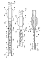
- Figure 1 illustrates a partially cross-sectioned plan view of a carrier tube and an elongate medical device disposed therein.
- the carrier tube is shown to be a packaging tube 10 having a packaging tube lumen 14 defined by a packaging tube wall 12 having an inner surface 16.
- the packaging tube lumen 14 can be sized to accommodate substantially the entire length of the elongate medical device 20 therein.
- the packaging tube lumen 14 can have an open proximal end and an open or closed distal end.
- the packaging tube is generally straight. However, it is recognized that the length of tubing can be configured in any shape desired, such as circles of increasing diameter to fix a particular packaging configuration.
- the packaging tube 10 can be formed utilizing conventional materials, dimensions and techniques.
- the packaging tube 10 can be formed of an extruded polymer including a blend of 50% polyolefin copolymer available under the trade name SURLYN and 50% high density polyethylene, having an inside diameter ranging from about 0.10 to about 0.30 inches (about 2.5 to about 7.6 millimeters), a wall thickness ranging from about 0.002 to about 0.020 inches (about 0.05 to about 0.5 millimeters), and a length ranging from about 12 to about 72 inches (about 30 to about 180 centimeters).
- thermoplastics such as fluoropolymers (PTFE, FEP, PFA, CTFE), nylons, phenylene oxides, polyesters, polyethylenes, polypropylene, polyurethanes and combinations thereof.
- the elongate medical device 20 can be removably disposed in the lumen 14 of the packaging tube 10.
- the elongate medical device 20 generically refers to a wide variety of elongate medical devices including intravascular devices such as catheters and guide wires.
- the elongate medical device 20 can include a balloon catheter, a guide catheter, a diagnostic catheter, a guidewire, a drug delivery catheter, an atherectomy catheter, a tubular sheath or a stent delivery catheter.
- the elongate medical device 20 may also include tracheal tubes, gastrostomy tubes, intravenous (IV) tubing, or other elongate devices used during a medical procedure.
- elongate medical device 20 is shown in the form of an intravascular balloon catheter 20 having an elongate shaft 22, a distally mounted balloon 24 and a stent 26 disposed thereon.
- a proximal portion 28 of the elongate shaft 22 is connected to a hub assembly 30.
- the hub assembly 30 includes a manifold 32 and a strain relief member 34.
- the proximal portion 28 of the elongate shaft 22 may extend through the strain relief member 34 and into the manifold 32.
- the hub assembly, or a portion thereof, may provide a shaft extension connected to the elongate shaft 22.
- the hub assembly 30 can be adhesively or thermally bonded to the proximal shaft portion 28.
- the proximal portion 28 of the elongate shaft 22 can be connected to the hub assembly 30 by an insert molding technique.
- the hub assembly 30 can be removably connected to the proximal shaft portion 28 utilizing a releasable compression fitting or other mechanical means.
- the manifold 32 and the strain relief member 34 can be a multi-piece construction, a two-piece construction, or a one-piece construction as shown. Examples of one-piece and two-piece constructions are described in U.S. Patent No. 6,273,404 to Holman et al. . In one-piece constructions, the manifold 32 and the strain relief member 34 can be formed of the same material, such as polycarbonate. Other moldable polymeric materials having sufficient impact resistance and chemical resistance can be utilized as well. In two-piece constructions, the manifold 32 and the strain relief member 34 can be formed of two different materials.
- the manifold 32 can be formed of polycarbonate, and the strain relief member 34 can be formed of a relatively less rigid polymer such as polyurethane available under the trade name PELLETHANE.
- polyurethane available under the trade name PELLETHANE.
- multiple materials may be used for different portions of the hub assembly 30 for their superior characteristics and compatibility.
- Alternative materials may be used for portions of the hub assembly 30, and the invention is not intended to be limited by the materials used for the hub assembly 30.
- the strain relief member 34 reduces the tendency of the proximal shaft portion 28 to kink just distal of the manifold 32.
- the manifold 32 can be relatively stiff and rigid, whereas the shaft 22 can be relatively flexible, which can create a stress concentration point therebetween, absent the strain relief member 34.
- the strain relief member 34 provides a gradual transition in stiffness between the manifold 32 and the proximal shaft portion 28.
- the strain relief member 34 has a helical shape and a gradual reduction in profile to provide such a transition in stiffness.
- the strain relief member 34 may be formed of various shapes, such as an elongated conical member.
- the manifold 32 includes a single port fluid connector 36 for connection to an ancillary device such as an inflation device (not shown).
- the manifold 32 can incorporate more than one connector 36, or no connector at all, depending on the type of elongated medical device 20 utilized. For example, an otherwise conventional guide wire may not require a fluid connector 36, whereas an otherwise conventional over-the-wire (OTW) type balloon catheter may require two port connections.
- OGW over-the-wire
- the hub assembly 30 includes a pair of wings 38 to facilitate easier handling and manipulation of the device 20.
- the particular shape and number of wings 38 can vary, depending on the manipulation requirements of the device 20 and design choices. In some instances, wings 38 may not be necessary or desirable.
- the hub assembly 30 includes an interference fit member (IFM) 40 disposed about a distal portion of the manifold 32, proximal of the strain relief member 34.
- the IFM 40 can be disposed about any portion of the hub assembly 30, to any portion of the proximal shaft 28, or to any portion of the strain relief member 34.
- the IFM 40 may be configured to provide an interference fit with the packaging tube 10.
- the IFM 40 can form an interference fit with any portion of the pacakging tube 10, such as the inside surface 16 of the packaging tube wall 12 as shown in Figure 1 .
- the packaging tube wall 12 and/or the IFM 40 can have sufficient compressibility to deform and thereby permit the IFM 40 to enter into the packaging tube lumen 14 despite a nominal difference in size.
- the interference fit between the IFM 40 and the packaging tube 10 establishes sufficient friction to resist gravitational and handling forces that can otherwise cause the device 20 to fall out of the packaging tube 10 prematurely.
- the friction created by the interference fit can also be sufficiently small to permit easy removal of the device 20 from the packaging tube 10 when desired as shown in Figure 2 .
- the IFM 40 and/or packaging tube 10 may be sized in order to provide sufficient interference force in order to retain the medical device 20 in packaging tube 10 until removal of medical device 20 is desired.
- the IFM 40 can be sized and shaped to be fully or partially disposed inside the packaging tube lumen 14. By extending the IFM 40 into the packaging tube lumen 14 a distance from the proximal end of the packaging tube 10, the IFM 40 is less likely to be accidentally dislodged by rough handling or the like. To this end, the IFM 40 can establish a contact surface area with the inside surface of the packaging tube wall 14 that is distal of the proximal end of the packaging tube 10.
- the IFM 40 includes a circumferential ring.
- the IFM 40 may be made from a number of materials, and the invention is not limited by the material of the IFM 40.
- the IFM 40 may comprise an elastomer, silicone, thermal plastic rubber, latex, polymer, or oil-based material. It is desirable that the IFM 40 comprises a medical grade material. It is preferred that the IFM 40 includes a material that is readily deformable and/or more compressible than the portion of the hub assembly 30 adjacent the IFM 40. Therefore, the shape of IFM 40 may be altered when inserted in the packaging tube 10 to provide an interference fit without damaging the shape or integrity of the elongate medical device 20.
- the IFM 40 may be a preformed component such as an O-ring or a lip seal, or the IFM 40 may be a bead placed on at least a portion of the hub assembly 30 and adhered to the hub assembly 30.
- the bead may be a silicone or latex caulk or a number of other elastomeric materials.
- the bead may be adhered to the hub assembly 30 by an adhesive, or the bead may be adhered by chemical or thermal bonding of the bead in contact with the hub assembly 30. It is contemplated that the bead may not be adhered to the hub assembly 30, but may be mechanically held in place by a circumferential channel or indentation on the hub assembly 30..
- the hub assembly 30 may include a channel 42.
- the channel 42 is preferably circumferential about a portion of the hub assembly 30.
- the channel 42 may be substantially helical or segmented.
- the channel may be molded into the hub assembly 30, or may be added in a later manufacturing process.
- the channel 42 may be a groove, a V-notch, a concave channel, a flat-bottomed channel, or other recessed area or indentation.
- the IFM 40 is disposed about at least a portion of the channel 42, wherein the channel 42 helps retain the IFM 40.
- the IFM 40 is sized in order to provide a raised surface above the outer surface of the hub assembly 30 adjacent the channel 42.
- the raised surface portion of the IFM 40 may be sized to provide an interference fit with the inner surface 16 of the packaging tube 10 in order to retain the elongate medical device 20 in the packaging tube 10.
- FIG. 4 illustrates a partial perspective view of an alternative embodiment of an elongate medical device 120.
- the elongate medical device 120 includes an elongate shaft 122 and a hub assembly 130 connected to a proximal portion 128 of the elongate shaft 122.
- the hub assembly 130 includes a manifold 132 having a distal portion fixed to a strain relief member 134. The portions of the hub assembly 130 may be substantially similar to those of hub assembly 30 or may contain any variations disclosed herein.
- the manifold 132 includes wings 138 and fluid port 136 similar to those of manifold 32.
- the manifold 132 also includes grips 133 disposed about a distal portion of the manifold 132 proximal the strain relief member 134. Grips 133 may facilitate operation and manipulation of the elongate medical device 120.
- the strain relief member 134 is connected to the manifold 132.
- the strain relief member 134 may be connected to the manifold 132 by mechanical means, chemical bonding, thermal bonding, compression fit, or other suitable means.
- manifold 132 may include a plurality of tabs 152 configured to engage with notches 154 in the strain relief member 134. Engagement of the tabs 152 in notches 154 provides a snap-fit securely fixing the strain relief member 134 to the manifold 132. It is contemplated that the strain relief member 134 may include tabs 152, and the manifold 132 may include notches 154. Other suitable locking means are within the scope of the invention.
- IFM 140 is disposed about a portion of the strain relief member 134.
- the IFM 140 may be substantially similar to IFM 40 described above.
- IFM 140 provides a raised surface around at least a portion of the strain relief member 134 in order to contact the inner surface 16 of the packaging tube 10.
- the strain relief member may include channel 142 for receiving at least a portion of the IFM 140.
- the channel 142 may help retain IFM 140 in a proper location.
- the channel 142 may be molded in the strain relief member 134 or may be added during a later manufacturing process.
- the channel 142 may be of a variety of shapes and sizes, and the invention is not intended to be limited by the type or shape of channel used.
- the channel 142 and IFM 140 are located at a position just distal of a transition portion of the strain relief member 134. However, it is contemplated that the channel 142 and the IFM 140 may be located at any position along the strain relief member 134.
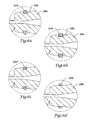
- Figures 6A-6J are cross-sectional views further illustrating alternative embodiments of the portion of a hub assembly, such as hub assembly 30/130, including an IFM, such as IFM 40/140.
- Figures 6A-6J refer to a portion of the hub assembly 30 identified in Figure 3 as a portion of the manifold 32, the portion of the hub assembly having an IFM as illustrated in Figures 6A-6J may be located on any portion of a manifold, a strain relief member, or a proximal portion of the elongate shaft.
- Figure 6A shows hub assembly portion 244 having a channel 242.
- Channel 242 is substantially flat-bottomed, but may take on a variety of shapes.
- the size and shape of the channel 242 is determined in order to accommodate IFM 240 and retain at least a position therein.
- the IFM 240 is disposed about at least a portion of channel 242, wherein a portion of IFM 240 extends above the surface of portion 244 adjacent IFM 240.
- IFM 240 comprises a generally circular cross-section.
- Figure 6B shows a portion 244 having a channel 242.
- IFM 240' is disposed about the channel 242.
- IFM 240' is shown to have a square cross-section, but could also be substantially rectangular.
- Figure 6C shows an alternative IFM 242" having a ramped portion to facilitate insertion in the packaging tube lumen 14.
- Figure 6D shows a portion 245 without a channel or groove.
- IFM 260 may be a bead formed or placed about portion 245.
- IFM 260 may be a generally flowable or liquid substance which solidifies upon placement about portion 245, or IFM 260 may be solid member disposed about portion 245.
- IFM 260 may be adhered to the portion 245 with an adhesive, or IFM 260 may be adhered by chemical or thermal bonding means.
- IFM 260 creates a raised surface about portion 245 in order to contact the inner surface 16 of the packaging tube 10.
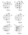
- Figures 6E and 6F illustrate a portion of an elongate medical device having multiple IFMs.
- Figure 6E shows a portion 246 having a channel 242' and channel 272.
- channels 242' and 272 may be concave channels.
- Channel 272 is shown to be larger than channel 242'.
- channels 272/242' may be substantially the same size.
- IFM 240 is disposed about channel 242' and IFM 270 is disposed about channel 272.
- IFM 270 is shown to be larger than IFM 240, but IFMs 240/270 may be substantially the same size.
- IFMs 240/270 may be sized to accommodate packaging tubes 10 having lumens 14 of differing sizes. Therefore, IFM 270 would be configured to engage the inner surface 16 of a packaging tube 10 in which IFM 240 would not create an interference fit. This arrangement allows more versatility and compatibility between elongate medical devices and packaging tubes.
- Figure 6F shows a tapered portion 247 of an elongate medical device.
- the tapered portion 247 includes a plurality of channels 242/282.
- Channel 282 may be substantially different in size and/or shape from channel 242, or channels 242/282 may be substantially similar.
- IFM 240 is disposed about the channel 242, and IFM 280 is disposed about the channel 282.
- IFM 280 may be substantially different in size and/or shape from IFM 240, or IFMs 240/280 may be substantially similar.
- IFMs 240/280 and/or channels 242/282 may be sized to accommodate packaging tubes 10 having lumens 14 of differing sizes.
- IFMs 240/280 and/or channels 242/282 may also be sized to create differing degrees of interference with the inner surface 16 of a packaging tube 10.
- the diameter D1 of channel 242 may be less than the diameter D2 of channel 282. This arrangement will provide IFM 280 with a larger outer diameter than IFM 240.
- IFM 290 shown in Figure 6G , may be a seal, such as a lip seal. IFM 290 may be disposed about portion 294. Portion 294 may include a channel 292, or portion 294 may comprise a substantially even surface.
- Figure 6H shows IFM 291 similar to IFM 290. IFM 291 includes a ramped surface for engaging the inner surface 16 of a packaging tube 10. IFM 291 may be disposed about channel 292.
- IFM 275 may be an elongated member. IFM 275 may be disposed about a tapered portion 274 of the elongate medical device.
- the tapered portion 274 may include an elongated channel 272 compatible for receiving at least a portion of the IFM 275.
- the tapered portion 274 may be formed without a channel.
- IFM 275 may be adhered to the tapered portion 274 by adhesive, chemical or thermal bonding means, or IFM 275 may not be adhered to the portion 274.
- IFM 275 may be elastically stretched about portion 274 in order to be compressively engaged with portion 274.
- IFM 275 may be made of a variety of materials suitable for engagement with the inner surface 16 of the packaging tube 10.
- the IFM 275 may have an outer circumference that varies along the length of the tapered portion 274. Therefore, the IFM 275 is compatible for providing an interference fit with a range of sizes of packaging tubes 10. Also, IFM 275 disposed about tapered portion 274 allows for varying degrees of interference between the tapered portion 274 and the inner surface 16 of the packaging tube 10. This arrangement allows for user-preferred variations of interference fits.
- FIG. 6J shows yet another embodiment of the present invention.
- Tapered portion 284 includes a helical channel 287 extending along tapered portion 284.
- IFM 285 is disposed about the helical channel 287.
- IFM 285 disposed helically about the tapered portion 284 is compatible for providing an interference fit with a range of sizes of packaging tubes 10.
- IFM 285 disposed about tapered portion 284 allows for varying degrees of interference between the tapered portion 284 and the inner surface 16 of the packaging tube 10.
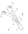
- FIG. 7 another embodiment of an elongate medical device 320 in accordance with the invention shows hub assembly 330 partially disposed in packaging tube 10.
- the hub assembly includes a manifold 332 and a strain relief member 334.
- the manifold 332 includes a plurality of proximal ports 336.
- An IFM 340 is disposed about a portion of the manifold 332.
- a channel 342 is provided around a portion of the manifold 332 for receiving the IFM 340.
- IFM 340 comprises a ring having a gap 341.
- the ring may have a circular cross-section or any other suitable cross-section.
- the gap 341 allows for expandable and compressible movement deeper into the channel of the IFM 340.
- the IFM 340 may be expanded in order to be disposed about channel 342. Further, the IFM 340 may be compressed in order to be disposed within the lumen 14 of the packaging tube 10. The IFM 340 then will expand in order to attempt to return to its static form. In doing so, the IFM 340 will engage the inner surface 16 of the packaging tube 10, creating an interference fit.
- the biasing force of the IFM 340 may be varied depending on the size, shape, and material of the IFM 340.
Landscapes
- Health & Medical Sciences (AREA)
- Life Sciences & Earth Sciences (AREA)
- General Health & Medical Sciences (AREA)
- Animal Behavior & Ethology (AREA)
- Engineering & Computer Science (AREA)
- Biomedical Technology (AREA)
- Heart & Thoracic Surgery (AREA)
- Veterinary Medicine (AREA)
- Public Health (AREA)
- Vascular Medicine (AREA)
- Cardiology (AREA)
- Oral & Maxillofacial Surgery (AREA)
- Transplantation (AREA)
- Biophysics (AREA)
- Pulmonology (AREA)
- Anesthesiology (AREA)
- Hematology (AREA)
- Media Introduction/Drainage Providing Device (AREA)
- Packaging Of Annular Or Rod-Shaped Articles, Wearing Apparel, Cassettes, Or The Like (AREA)
- Orthopedics, Nursing, And Contraception (AREA)
Claims (23)
- Längliches Medizinprodukt, das zum Verpacken in einem allgemein röhrenförmigen Teil geeignet ist, wobei das allgemein röhrenförmige Teil (10) ein Lumen (14) hat, das durch eine Innenfläche (16) gebildet ist, wobei das längliche Medizinprodukt (20) aufweist:einen länglichen Schaft (22);eine Zentralanordnung (30), die mit dem länglichen Schaft (22) verbunden ist, wobei die Zentralanordnung (30) mindestens einen Abschnitt aufweist, der aus einem ersten Material hergestellt ist; undein Presspassungsteil (40) mit einem zweiten Material, das um mindestens einen Teil des Abschnitts der Zentralanordnung (30) mit dem ersten Material angeordnet ist, wobei das Presspassungsteil (40) so konfiguriert ist, dass es eine Presspassung mit der Innenfläche (16) des allgemein röhrenförmigen Teils (10) bildet, wenn der längliche Schaft (22) und das Presspassungsteil (40) im Lumen (14) des allgemein röhrenförmigen Teils (10) angeordnet sind.
- Längliches Medizinprodukt nach Anspruch 1, wobei die Zentralanordnung (30) ferner aufweist:einen distalen Abschnitt mit mindestens einem Segment, das einen allgemein kreisförmigen Querschnitt mit dem ersten Material hat; undeinen Kanal (42), der sich um das Segment des distalen Abschnitts der Zentralanordnung (30) mit dem ersten Material über den Umfang erstreckt, wobei das Presspassungsteil (40) um den Kanal (42) angeordnet ist.
- Längliches Medizinprodukt nach Anspruch 1, wobei die Zentralanordnung (30) ferner aufweist:ein Anschlussstück (32), das einen distalen Abschnitt mit dem ersten Material hat, wobei das Presspassungsteil um den distalen Abschnitt des Anschlussstücks (32) angeordnet ist.
- Längliches Medizinprodukt nach Anspruch 3, wobei die Zentralanordnung (30) ferner aufweist:ein Zugentlastungsteil (34), wobei das Anschlussstück (32) und das Zugentlastungsteil (34) in einem Stück ausgebildet sind.
- Längliches Medizinprodukt nach Anspruch 1, wobei die Zentralanordnung ferner aufweist:ein Zugentlastungsteil (34), wobei das Presspassungsteil um das Zugentlastungsteil (34) angeordnet ist.
- Längliches Medizinprodukt nach Anspruch 5, wobei die Zentralanordnung ferner aufweist:ein Anschlussstück (32), wobei das Zugentlastungsteil (34) am Anschlussstück (32) befestigt ist.
- Längliches Medizinprodukt nach Anspruch 1, wobei das zweite Material komprimierbarer als das erste Material ist.
- Längliches Medizinprodukt nach Anspruch 1, wobei das zweite Material im Vergleich zum ersten Material leicht verformbar ist.
- Längliches Medizinprodukt nach Anspruch 1, wobei das zweite Material elastomer ist.
- Längliches Medizinprodukt nach Anspruch 1, wobei das Presspassungsteil eine Wulst ist, die am ersten Material haftet.
- Längliches Medizinprodukt nach Anspruch 1, wobei das Presspassungsteil (40) ein O-Ring ist.
- Längliches Medizinprodukt nach Anspruch 11, wobei der O-Ring Silikon aufweist.
- Längliches Medizinprodukt nach Anspruch 1, wobei das Presspassungsteil (40) eine längliche elastomere Hülse ist.
- Längliches Medizinprodukt nach Anspruch 1, wobei der längliche Schaft (22) einen proximalen Abschnitt (28) hat.
- Längliches Medizinprodukt nach Anspruch 14, wobei die Zentralanordnung (30) mit dem proximalen Abschnitt (28) des länglichen Schafts (22) verbunden ist.
- Längliches Medizinprodukt nach Anspruch 15, wobei der aus dem ersten Material hergestellte Abschnitt der Zentralanordnung (30) einen Umfangskanal aufweist.
- Längliches Medizinprodukt nach Anspruch 16, wobei die Presspassung ein Umfangspresspassungsteil ist, das ein elastomeres Material aufweist, wobei das Umfangspresspassungsteil um mindestens einen Abschnitt des Umfangskanals angeordnet ist.
- Längliches Medizinprodukt nach Anspruch 17, wobei die Zentralanordnung (30) ferner aufweist:ein Anschlussstück (32), das einen distalen Abschnitt mit dem ersten Material hat, wobei das Umfangspresspassungsteil (40) um den distalen Abschnitt des Anschlussstücks angeordnet ist.
- Längliches Medizinprodukt nach Anspruch 18, wobei die Zentralanordnung ferner aufweist:ein Zugentlastungsteil (34), wobei das Anschlussstück (32) und das Zugentlastungsteil (34) in einem Stück ausgebildet sind.
- Längliches Medizinprodukt nach Anspruch 17, wobei die Zentralanordnung ferner aufweist:ein Zugentlastungsteil (34), wobei das Umfangspresspassungsteil (40) um das Zugentlastungsteil (34) angeordnet ist.
- Längliches Medizinprodukt nach Anspruch 20, wobei die Zentralanordnung ferner aufweist:ein Anschlussstück (32), wobei das Zugentlastungsteil (34) am Anschlussstück (32) befestigt ist.
- Längliches Medizinprodukt nach Anspruch 17, wobei das Umfangspresspassungsteil (40) ein O-Ring ist.
- Längliches Medizinprodukt nach Anspruch 17, wobei das Umfangspresspassungsteil (40) eine längliche Hülse ist.
Applications Claiming Priority (2)
| Application Number | Priority Date | Filing Date | Title |
|---|---|---|---|
| US10/667,936 US8012144B2 (en) | 2003-09-22 | 2003-09-22 | Elongate medical device having an interference fit packaging member |
| PCT/US2004/030217 WO2005030309A2 (en) | 2003-09-22 | 2004-09-16 | Elongate medical device having an interference fit packaging member |
Publications (2)
| Publication Number | Publication Date |
|---|---|
| EP1670535A2 EP1670535A2 (de) | 2006-06-21 |
| EP1670535B1 true EP1670535B1 (de) | 2011-04-20 |
Family
ID=34313399
Family Applications (1)
| Application Number | Title | Priority Date | Filing Date |
|---|---|---|---|
| EP04784169A Expired - Lifetime EP1670535B1 (de) | 2003-09-22 | 2004-09-16 | Längliches medizinprodukt mit einem interferenz-passungs-verpackungselement |
Country Status (7)
| Country | Link |
|---|---|
| US (1) | US8012144B2 (de) |
| EP (1) | EP1670535B1 (de) |
| JP (1) | JP2007521105A (de) |
| AT (1) | ATE506097T1 (de) |
| CA (1) | CA2538685C (de) |
| DE (1) | DE602004032364D1 (de) |
| WO (1) | WO2005030309A2 (de) |
Families Citing this family (33)
| Publication number | Priority date | Publication date | Assignee | Title |
|---|---|---|---|---|
| US7712606B2 (en) * | 2005-09-13 | 2010-05-11 | Sadra Medical, Inc. | Two-part package for medical implant |
| JP4887810B2 (ja) * | 2006-01-31 | 2012-02-29 | 日本ゼオン株式会社 | カテーテル挿入具およびカテーテル挿入具セット |
| USD588906S1 (en) * | 2007-04-26 | 2009-03-24 | Tokuyama Corporation | Package |
| US8968210B2 (en) * | 2008-10-01 | 2015-03-03 | Covidien LLP | Device for needle biopsy with integrated needle protection |
| US9186128B2 (en) | 2008-10-01 | 2015-11-17 | Covidien Lp | Needle biopsy device |
| US11298113B2 (en) | 2008-10-01 | 2022-04-12 | Covidien Lp | Device for needle biopsy with integrated needle protection |
| US20110190662A1 (en) * | 2008-10-01 | 2011-08-04 | Beacon Endoscopic Corporation | Rapid exchange fna biopsy device with diagnostic and therapeutic capabilities |
| US9782565B2 (en) | 2008-10-01 | 2017-10-10 | Covidien Lp | Endoscopic ultrasound-guided biliary access system |
| US9332973B2 (en) | 2008-10-01 | 2016-05-10 | Covidien Lp | Needle biopsy device with exchangeable needle and integrated needle protection |
| USD600112S1 (en) * | 2009-04-03 | 2009-09-15 | Becton, Dickinson And Company | Packaging for surgical blade tips |
| USD617634S1 (en) * | 2009-04-03 | 2010-06-15 | Becton, Dickinson And Company | Packaging for surgical blade tips with wrench |
| USD617182S1 (en) * | 2009-04-03 | 2010-06-08 | Becton, Dickinson And Company | Packaging for surgical blade tips with stand |
| USD603253S1 (en) * | 2009-04-03 | 2009-11-03 | Becton, Dickinson And Company | Packaging for surgical blade tips with stand and guide |
| JP5956335B2 (ja) * | 2010-06-30 | 2016-07-27 | テルモ株式会社 | カテーテル |
| USD679803S1 (en) * | 2011-09-27 | 2013-04-09 | Quest Medical, Inc. | Balloon catheter |
| IN2014DN03315A (de) | 2011-10-19 | 2015-06-26 | Bayer Medical Care Inc | |
| JP5908270B2 (ja) | 2011-12-12 | 2016-04-26 | テルモ株式会社 | カテーテル |
| CN105492038B (zh) | 2013-06-14 | 2019-10-01 | 拜耳医药保健有限公司 | 便携式流体输送系统 |
| US10549084B2 (en) | 2014-01-10 | 2020-02-04 | Bayer Healthcare Llc | Single-use disposable set connector |
| HRP20250654T1 (hr) | 2015-01-09 | 2025-07-18 | Bayer Healthcare Llc | Višestruki sustav za isporuku tekućine s višenamjenskim jednokratnim kompletom i njegove značajke |
| US11660439B2 (en) | 2015-07-02 | 2023-05-30 | Covellus Llc | Modular medical device system |
| US20170000247A1 (en) * | 2015-07-02 | 2017-01-05 | Eitam Scharf | Card with embedded tools |
| US10328250B2 (en) | 2015-07-02 | 2019-06-25 | Covellus Llc | Medical device adapter |
| US10814120B2 (en) | 2015-07-02 | 2020-10-27 | Covellus Llc | Modular medical device catheter system |
| TWI651107B (zh) | 2016-06-15 | 2019-02-21 | 拜耳保健公司 | 多次使用可棄式系統及用於該系統之注射器 |
| WO2019090320A1 (en) | 2017-11-06 | 2019-05-09 | Covellus Llc | Modular medical device catheter system |
| EP3706852B1 (de) * | 2017-11-06 | 2024-04-17 | Covellus LLC | Kathetersystem mit modularer medizinischer vorrichtung |
| US20200352693A1 (en) * | 2017-12-11 | 2020-11-12 | Spinal Balance, Inc. | Package for the containment, handling, and delivery of interbody cages |
| US10820755B2 (en) | 2018-09-19 | 2020-11-03 | The Violina Syndicate Llc | Herb grinder with enhanced grinding features |
| US11612723B2 (en) * | 2018-11-28 | 2023-03-28 | Becton, Dickinson And Company | Needle cover retention |
| USD892321S1 (en) * | 2019-06-13 | 2020-08-04 | William Charles Brian Newton | Syringe adapter |
| US20210370022A1 (en) * | 2020-05-28 | 2021-12-02 | Incept, Llc | Anchoring strain relief member |
| US12329918B2 (en) * | 2020-06-09 | 2025-06-17 | Becton, Dickinson And Company | Needle cover retention |
Family Cites Families (72)
| Publication number | Priority date | Publication date | Assignee | Title |
|---|---|---|---|---|
| US2185741A (en) * | 1938-07-05 | 1940-01-02 | Lloyd F Sorg | Hose attachment |
| US3042045A (en) * | 1958-07-02 | 1962-07-03 | David S Sheridan | Medico-surgical tubes having integral connectors formed in their ends |
| BE620748A (de) * | 1961-07-29 | |||
| US3307552A (en) * | 1963-03-25 | 1967-03-07 | Lillian T Strawn | Catheter plug and shield device |
| US3318335A (en) * | 1963-10-15 | 1967-05-09 | Chester M Heller | Torsional pipe coupling |
| US3470869A (en) * | 1965-07-09 | 1969-10-07 | Cleveland Clinic Foundation | Apparatus for gastro-intestinal barium air contrast spraying |
| US3725522A (en) * | 1969-09-23 | 1973-04-03 | D Sheridan | Method of manufacture of balloon-type catheters |
| FR2092970A6 (de) | 1970-04-28 | 1972-01-28 | Durand Herve | |
| US3861972A (en) * | 1970-08-24 | 1975-01-21 | Johnson & Johnson | Intravenous catheter |
| US3720210A (en) * | 1971-03-03 | 1973-03-13 | Baxter Laboratories Inc | Indwelling catheter device |
| US3752510A (en) * | 1971-10-07 | 1973-08-14 | Sherwood Medical Ind Inc | Structure for connecting a flexible tube to a syringe |
| US3873391A (en) * | 1972-07-19 | 1975-03-25 | Johns Manville | Method of fabricating a plastic pipe fitting |
| US3989571A (en) * | 1973-04-23 | 1976-11-02 | American Hospital Supply Corporation | Method of making a smooth tipped endotracheal tube |
| US4210478A (en) * | 1973-05-08 | 1980-07-01 | International Paper Company | Method of making a catheter |
| US3865666A (en) * | 1973-05-08 | 1975-02-11 | Int Paper Co | Method of making a catheter |
| US3950052A (en) * | 1974-03-15 | 1976-04-13 | Clairol Incorporated | Swivelling electrical connection |
| US3914002A (en) * | 1974-04-17 | 1975-10-21 | Sherwood Medical Ind Inc | Conductive tubing and method of making same |
| US3959429A (en) * | 1975-02-03 | 1976-05-25 | International Paper Company | Method of making a retention catheter and molding a tip thereon |
| US4085185A (en) * | 1975-04-03 | 1978-04-18 | Adair Edwin Lloyd | Method of sealing concentric tube ends to make sealed dual-wall tube |
| US3985601A (en) * | 1975-05-05 | 1976-10-12 | Quantum, Inc. | Method for producing a balloon type catheter having a smooth continuous outer surface |
| GB1552129A (en) * | 1975-07-16 | 1979-09-05 | Warne Surgical Products Ltd | Manufacture of surgical catheters and tubes |
| US4247968A (en) * | 1975-08-04 | 1981-02-03 | Textron, Inc. | Fastener stringer with tubular filament element |
| US4171943A (en) * | 1976-11-18 | 1979-10-23 | Teleflex Incorporated | Apparatus for forming a catheter |
| US4130304A (en) * | 1977-08-12 | 1978-12-19 | Don R. Hinderliter, Inc. | Well head seal assembly |
| US4191185A (en) * | 1977-09-06 | 1980-03-04 | Johnson & Johnson | Catheter assembly |
| US4154244A (en) * | 1977-11-21 | 1979-05-15 | Baxter Travenol Laboratories, Inc. | Balloon-type catheter |
| US4198983A (en) * | 1978-04-28 | 1980-04-22 | Baxter Travenol Laboratories, Inc. | Catheter made of a thermoplastic material having improved softness and low friction |
| US4207900A (en) * | 1978-07-03 | 1980-06-17 | The Kendall Company | Insert molded catheter and method |
| US4284459A (en) * | 1978-07-03 | 1981-08-18 | The Kendall Company | Method for making a molded catheter |
| US4328056A (en) * | 1980-07-09 | 1982-05-04 | Sherwood Medical Industries Inc. | Method of making a cuffed tube |
| US4354495A (en) * | 1980-10-30 | 1982-10-19 | Sherwood Medical Industries Inc. | Method of connecting plastic tube to a plastic part |
| US4511163A (en) * | 1982-07-14 | 1985-04-16 | Mead Johnson & Company | Adaptable tip tubing connector |
| US4489961A (en) * | 1983-04-18 | 1984-12-25 | The Singer Company | Terminal for flexible tube |
| US4509877A (en) * | 1983-11-09 | 1985-04-09 | Sobin Sidney S | Tapered torque strain relief coupling |
| US4692150A (en) * | 1985-09-25 | 1987-09-08 | The Kendall Company | Tamper evident band |
| US4607746A (en) * | 1985-09-25 | 1986-08-26 | Cordis Corporation | Packaging tube |
| US5181913A (en) * | 1987-03-09 | 1993-01-26 | Prn Services, Inc. | Catheter with check valve and rolled sheath |
| GB8802935D0 (en) * | 1988-02-09 | 1988-03-09 | Ems Medical Group Ltd | Dispenser for surgical guidewire |
| DE3933305A1 (de) * | 1989-10-05 | 1991-04-18 | United Carr Gmbh Trw | Halteelement aus kunststoff |
| US5031775A (en) * | 1990-02-14 | 1991-07-16 | Angeion Corporation | Medical instrument holder |
| US5125906A (en) * | 1990-11-02 | 1992-06-30 | Arrow International Investment Corporation | Hand-held device for feeding a spring wire guide |
| US5217114A (en) * | 1991-05-15 | 1993-06-08 | Applied Vascular Devices, Inc. | Catheter package |
| US5976107A (en) * | 1991-07-05 | 1999-11-02 | Scimed Life Systems. Inc. | Catheter having extendable guide wire lumen |
| US5372592A (en) * | 1992-06-22 | 1994-12-13 | C. R. Bard, Inc. | Method and device for preparing catheters prior to use |
| US5380301A (en) * | 1992-07-10 | 1995-01-10 | Sherwood Medical Company | Catheter/hub strain relief and method of manufacture thereof |
| US5344011A (en) * | 1993-02-12 | 1994-09-06 | Advanced Cardiovascular Systems, Inc. | Packaging system for an elongated flexible product |
| US5309604A (en) * | 1993-03-11 | 1994-05-10 | Merit Medical Systems, Inc. | Coiling/uncoiling device for tubing |
| US5364355A (en) * | 1993-06-18 | 1994-11-15 | Advanced Cardiovascular Systems, Inc. | Holding system for coiled intravascular products |
| US5366444A (en) * | 1993-07-06 | 1994-11-22 | Med-Pro Design, Inc. | Hand operated guide wire advancement device |
| US5417659A (en) * | 1993-07-20 | 1995-05-23 | Devon Industries, Inc. | Surgical instrument sharp end foil |
| US5419764A (en) * | 1994-01-19 | 1995-05-30 | Roll; John D. | Percutaneous twisting lock catheter |
| US5531701A (en) * | 1994-06-06 | 1996-07-02 | Luther Medical Products, Inc. | Over-the-needle catheter |
| US5569222A (en) * | 1994-06-21 | 1996-10-29 | Clintec Nutrition Company | Adapter for a variety of tubes having various diameters and a method of using the adapter |
| US5607055A (en) * | 1995-03-14 | 1997-03-04 | Mallinckrodt Medical, Inc. | Vacuum package for flexible products |
| DE19518628C1 (de) * | 1995-05-20 | 1996-09-26 | Rasmussen Gmbh | Haltevorrichtung zur Lagesicherung einer Schlauchschelle |
| US6273404B1 (en) * | 1995-06-05 | 2001-08-14 | Scimed Life Systems, Inc. | Method of making monolithic hub and strain relief |
| US6231564B1 (en) * | 1995-09-29 | 2001-05-15 | Medtronic Ave, Inc. | Storable guidewire system |
| EP0782868A1 (de) | 1996-01-08 | 1997-07-09 | Schneider (Europe) Ag | Verpackungssystem |
| US5755225A (en) * | 1996-09-30 | 1998-05-26 | Hutson & Associates, Inc. | Medical tube-retaining device |
| WO1998014232A1 (en) * | 1996-10-03 | 1998-04-09 | Dubrul William R | Self coiling catheter |
| IES960752A2 (en) * | 1996-10-25 | 1997-07-16 | Bard Connaught | An improved catheter packaging system |
| US5928208A (en) * | 1997-08-29 | 1999-07-27 | Boston Scientific Corporation | Retention mechanism for catheter with distal anchor |
| US5941849A (en) * | 1997-08-29 | 1999-08-24 | Scimed Life Systems, Inc. | Suture retention device |
| US6068622A (en) * | 1998-02-10 | 2000-05-30 | Medtronic Inc. | Single piece hub/strain relief that can be injection molded over a shaft |
| US6068121A (en) * | 1998-03-11 | 2000-05-30 | Schneider (Usa) Inc. | Universal catheter tray |
| US5954707A (en) * | 1998-06-15 | 1999-09-21 | Uni-Cath Inc. | Catheter with locking device |
| US6228073B1 (en) * | 1998-12-15 | 2001-05-08 | Medtronic, Inc. | Angiography luer hub having wings proximal to the plurality of grips and strain relief |
| US6186325B1 (en) * | 1999-03-11 | 2001-02-13 | Ethicon, Inc. | Packaging of catheter products |
| US6405414B1 (en) * | 1999-05-19 | 2002-06-18 | Contech Packaging, Inc. | Coiling clip and improved spiral wound dispenser |
| US6551273B1 (en) * | 2000-08-23 | 2003-04-22 | Scimed Life Systems, Inc. | Catheter having a shaft keeper |
| US7214220B2 (en) * | 2001-09-21 | 2007-05-08 | Boston Scientific Scimed, Inc. | Intravascular device with carrier tube engagement member |
| US7625365B2 (en) * | 2001-09-21 | 2009-12-01 | Boston Scientific Scimed, Inc. | Intravascular device and carrier tube with interference fit member |
-
2003
- 2003-09-22 US US10/667,936 patent/US8012144B2/en active Active
-
2004
- 2004-09-16 WO PCT/US2004/030217 patent/WO2005030309A2/en not_active Ceased
- 2004-09-16 EP EP04784169A patent/EP1670535B1/de not_active Expired - Lifetime
- 2004-09-16 DE DE602004032364T patent/DE602004032364D1/de not_active Expired - Lifetime
- 2004-09-16 AT AT04784169T patent/ATE506097T1/de not_active IP Right Cessation
- 2004-09-16 CA CA2538685A patent/CA2538685C/en not_active Expired - Fee Related
- 2004-09-16 JP JP2006527001A patent/JP2007521105A/ja active Pending
Also Published As
| Publication number | Publication date |
|---|---|
| WO2005030309A2 (en) | 2005-04-07 |
| US20050061697A1 (en) | 2005-03-24 |
| ATE506097T1 (de) | 2011-05-15 |
| WO2005030309A3 (en) | 2008-01-17 |
| DE602004032364D1 (de) | 2011-06-01 |
| JP2007521105A (ja) | 2007-08-02 |
| US8012144B2 (en) | 2011-09-06 |
| CA2538685C (en) | 2012-05-29 |
| CA2538685A1 (en) | 2005-04-07 |
| EP1670535A2 (de) | 2006-06-21 |
Similar Documents
| Publication | Publication Date | Title |
|---|---|---|
| EP1670535B1 (de) | Längliches medizinprodukt mit einem interferenz-passungs-verpackungselement | |
| US7214220B2 (en) | Intravascular device with carrier tube engagement member | |
| US7625365B2 (en) | Intravascular device and carrier tube with interference fit member | |
| US11793989B2 (en) | Distal valve for a catheter | |
| US9168359B2 (en) | Modular introducer and exchange sheath | |
| US7985232B2 (en) | Detachable hemostasis valve and splittable sheath assembly | |
| US9884167B2 (en) | Catheter with partially slitted insertion aid | |
| US8066693B2 (en) | Catheter device | |
| AU2002336578B9 (en) | Tube having a retention member | |
| CN101970925B (zh) | 具有光滑孔的倒钩式夹紧装置 | |
| US20100268163A1 (en) | Modular introducer and exchange sheath | |
| US9345853B2 (en) | Tube assembly and method for making the assembly | |
| AU2005234786A1 (en) | Dual purpose adapter | |
| EP1931412A1 (de) | Einführinstrument und austauschhülse |
Legal Events
| Date | Code | Title | Description |
|---|---|---|---|
| PUAI | Public reference made under article 153(3) epc to a published international application that has entered the european phase |
Free format text: ORIGINAL CODE: 0009012 |
|
| 17P | Request for examination filed |
Effective date: 20060331 |
|
| AK | Designated contracting states |
Kind code of ref document: A2 Designated state(s): AT BE BG CH CY CZ DE DK EE ES FI FR GB GR HU IE IT LI LU MC NL PL PT RO SE SI SK TR |
|
| AX | Request for extension of the european patent |
Extension state: AL HR LT LV MK |
|
| DAX | Request for extension of the european patent (deleted) | ||
| PUAK | Availability of information related to the publication of the international search report |
Free format text: ORIGINAL CODE: 0009015 |
|
| RIC1 | Information provided on ipc code assigned before grant |
Ipc: A61M 25/00 20060101AFI20080128BHEP Ipc: A61F 2/00 20060101ALI20080128BHEP |
|
| 17Q | First examination report despatched |
Effective date: 20080421 |
|
| GRAP | Despatch of communication of intention to grant a patent |
Free format text: ORIGINAL CODE: EPIDOSNIGR1 |
|
| GRAC | Information related to communication of intention to grant a patent modified |
Free format text: ORIGINAL CODE: EPIDOSCIGR1 |
|
| GRAS | Grant fee paid |
Free format text: ORIGINAL CODE: EPIDOSNIGR3 |
|
| GRAA | (expected) grant |
Free format text: ORIGINAL CODE: 0009210 |
|
| AK | Designated contracting states |
Kind code of ref document: B1 Designated state(s): AT BE BG CH CY CZ DE DK EE ES FI FR GB GR HU IE IT LI LU MC NL PL PT RO SE SI SK TR |
|
| REG | Reference to a national code |
Ref country code: GB Ref legal event code: FG4D |
|
| REG | Reference to a national code |
Ref country code: CH Ref legal event code: EP |
|
| REG | Reference to a national code |
Ref country code: IE Ref legal event code: FG4D |
|
| REF | Corresponds to: |
Ref document number: 602004032364 Country of ref document: DE Date of ref document: 20110601 Kind code of ref document: P |
|
| REG | Reference to a national code |
Ref country code: DE Ref legal event code: R096 Ref document number: 602004032364 Country of ref document: DE Effective date: 20110601 |
|
| REG | Reference to a national code |
Ref country code: NL Ref legal event code: VDEP Effective date: 20110420 |
|
| PG25 | Lapsed in a contracting state [announced via postgrant information from national office to epo] |
Ref country code: PT Free format text: LAPSE BECAUSE OF FAILURE TO SUBMIT A TRANSLATION OF THE DESCRIPTION OR TO PAY THE FEE WITHIN THE PRESCRIBED TIME-LIMIT Effective date: 20110822 Ref country code: SE Free format text: LAPSE BECAUSE OF FAILURE TO SUBMIT A TRANSLATION OF THE DESCRIPTION OR TO PAY THE FEE WITHIN THE PRESCRIBED TIME-LIMIT Effective date: 20110420 |
|
| PG25 | Lapsed in a contracting state [announced via postgrant information from national office to epo] |
Ref country code: BE Free format text: LAPSE BECAUSE OF FAILURE TO SUBMIT A TRANSLATION OF THE DESCRIPTION OR TO PAY THE FEE WITHIN THE PRESCRIBED TIME-LIMIT Effective date: 20110420 Ref country code: AT Free format text: LAPSE BECAUSE OF FAILURE TO SUBMIT A TRANSLATION OF THE DESCRIPTION OR TO PAY THE FEE WITHIN THE PRESCRIBED TIME-LIMIT Effective date: 20110420 Ref country code: GR Free format text: LAPSE BECAUSE OF FAILURE TO SUBMIT A TRANSLATION OF THE DESCRIPTION OR TO PAY THE FEE WITHIN THE PRESCRIBED TIME-LIMIT Effective date: 20110721 Ref country code: FI Free format text: LAPSE BECAUSE OF FAILURE TO SUBMIT A TRANSLATION OF THE DESCRIPTION OR TO PAY THE FEE WITHIN THE PRESCRIBED TIME-LIMIT Effective date: 20110420 Ref country code: ES Free format text: LAPSE BECAUSE OF FAILURE TO SUBMIT A TRANSLATION OF THE DESCRIPTION OR TO PAY THE FEE WITHIN THE PRESCRIBED TIME-LIMIT Effective date: 20110731 Ref country code: CY Free format text: LAPSE BECAUSE OF FAILURE TO SUBMIT A TRANSLATION OF THE DESCRIPTION OR TO PAY THE FEE WITHIN THE PRESCRIBED TIME-LIMIT Effective date: 20110420 Ref country code: SI Free format text: LAPSE BECAUSE OF FAILURE TO SUBMIT A TRANSLATION OF THE DESCRIPTION OR TO PAY THE FEE WITHIN THE PRESCRIBED TIME-LIMIT Effective date: 20110420 |
|
| PG25 | Lapsed in a contracting state [announced via postgrant information from national office to epo] |
Ref country code: NL Free format text: LAPSE BECAUSE OF FAILURE TO SUBMIT A TRANSLATION OF THE DESCRIPTION OR TO PAY THE FEE WITHIN THE PRESCRIBED TIME-LIMIT Effective date: 20110420 |
|
| PG25 | Lapsed in a contracting state [announced via postgrant information from national office to epo] |
Ref country code: CZ Free format text: LAPSE BECAUSE OF FAILURE TO SUBMIT A TRANSLATION OF THE DESCRIPTION OR TO PAY THE FEE WITHIN THE PRESCRIBED TIME-LIMIT Effective date: 20110420 Ref country code: EE Free format text: LAPSE BECAUSE OF FAILURE TO SUBMIT A TRANSLATION OF THE DESCRIPTION OR TO PAY THE FEE WITHIN THE PRESCRIBED TIME-LIMIT Effective date: 20110420 |
|
| PLBE | No opposition filed within time limit |
Free format text: ORIGINAL CODE: 0009261 |
|
| STAA | Information on the status of an ep patent application or granted ep patent |
Free format text: STATUS: NO OPPOSITION FILED WITHIN TIME LIMIT |
|
| PG25 | Lapsed in a contracting state [announced via postgrant information from national office to epo] |
Ref country code: DK Free format text: LAPSE BECAUSE OF FAILURE TO SUBMIT A TRANSLATION OF THE DESCRIPTION OR TO PAY THE FEE WITHIN THE PRESCRIBED TIME-LIMIT Effective date: 20110420 Ref country code: RO Free format text: LAPSE BECAUSE OF FAILURE TO SUBMIT A TRANSLATION OF THE DESCRIPTION OR TO PAY THE FEE WITHIN THE PRESCRIBED TIME-LIMIT Effective date: 20110420 Ref country code: SK Free format text: LAPSE BECAUSE OF FAILURE TO SUBMIT A TRANSLATION OF THE DESCRIPTION OR TO PAY THE FEE WITHIN THE PRESCRIBED TIME-LIMIT Effective date: 20110420 Ref country code: PL Free format text: LAPSE BECAUSE OF FAILURE TO SUBMIT A TRANSLATION OF THE DESCRIPTION OR TO PAY THE FEE WITHIN THE PRESCRIBED TIME-LIMIT Effective date: 20110420 |
|
| 26N | No opposition filed |
Effective date: 20120123 |
|
| PG25 | Lapsed in a contracting state [announced via postgrant information from national office to epo] |
Ref country code: MC Free format text: LAPSE BECAUSE OF NON-PAYMENT OF DUE FEES Effective date: 20110930 |
|
| REG | Reference to a national code |
Ref country code: CH Ref legal event code: PL |
|
| REG | Reference to a national code |
Ref country code: DE Ref legal event code: R097 Ref document number: 602004032364 Country of ref document: DE Effective date: 20120123 |
|
| GBPC | Gb: european patent ceased through non-payment of renewal fee |
Effective date: 20110916 |
|
| PG25 | Lapsed in a contracting state [announced via postgrant information from national office to epo] |
Ref country code: IT Free format text: LAPSE BECAUSE OF FAILURE TO SUBMIT A TRANSLATION OF THE DESCRIPTION OR TO PAY THE FEE WITHIN THE PRESCRIBED TIME-LIMIT Effective date: 20110420 |
|
| REG | Reference to a national code |
Ref country code: FR Ref legal event code: ST Effective date: 20120531 |
|
| PG25 | Lapsed in a contracting state [announced via postgrant information from national office to epo] |
Ref country code: LI Free format text: LAPSE BECAUSE OF NON-PAYMENT OF DUE FEES Effective date: 20110930 Ref country code: CH Free format text: LAPSE BECAUSE OF NON-PAYMENT OF DUE FEES Effective date: 20110930 |
|
| PG25 | Lapsed in a contracting state [announced via postgrant information from national office to epo] |
Ref country code: FR Free format text: LAPSE BECAUSE OF NON-PAYMENT OF DUE FEES Effective date: 20110930 Ref country code: GB Free format text: LAPSE BECAUSE OF NON-PAYMENT OF DUE FEES Effective date: 20110916 |
|
| PG25 | Lapsed in a contracting state [announced via postgrant information from national office to epo] |
Ref country code: LU Free format text: LAPSE BECAUSE OF NON-PAYMENT OF DUE FEES Effective date: 20110916 |
|
| PG25 | Lapsed in a contracting state [announced via postgrant information from national office to epo] |
Ref country code: BG Free format text: LAPSE BECAUSE OF FAILURE TO SUBMIT A TRANSLATION OF THE DESCRIPTION OR TO PAY THE FEE WITHIN THE PRESCRIBED TIME-LIMIT Effective date: 20110720 |
|
| PG25 | Lapsed in a contracting state [announced via postgrant information from national office to epo] |
Ref country code: TR Free format text: LAPSE BECAUSE OF FAILURE TO SUBMIT A TRANSLATION OF THE DESCRIPTION OR TO PAY THE FEE WITHIN THE PRESCRIBED TIME-LIMIT Effective date: 20110420 |
|
| PG25 | Lapsed in a contracting state [announced via postgrant information from national office to epo] |
Ref country code: HU Free format text: LAPSE BECAUSE OF FAILURE TO SUBMIT A TRANSLATION OF THE DESCRIPTION OR TO PAY THE FEE WITHIN THE PRESCRIBED TIME-LIMIT Effective date: 20110420 |
|
| REG | Reference to a national code |
Ref country code: DE Ref legal event code: R082 Ref document number: 602004032364 Country of ref document: DE Representative=s name: VOSSIUS & PARTNER PATENTANWAELTE RECHTSANWAELT, DE |
|
| REG | Reference to a national code |
Ref country code: DE Ref legal event code: R082 Ref document number: 602004032364 Country of ref document: DE Representative=s name: VOSSIUS & PARTNER PATENTANWAELTE RECHTSANWAELT, DE Effective date: 20150202 Ref country code: DE Ref legal event code: R081 Ref document number: 602004032364 Country of ref document: DE Owner name: BOSTON SCIENTIFIC LIMITED, BM Free format text: FORMER OWNER: BOSTON SCIENTIFIC LTD., ST. MICHAEL, BARBADOS, BB Effective date: 20150202 |
|
| PGFP | Annual fee paid to national office [announced via postgrant information from national office to epo] |
Ref country code: IE Payment date: 20190910 Year of fee payment: 16 Ref country code: DE Payment date: 20190903 Year of fee payment: 16 |
|
| REG | Reference to a national code |
Ref country code: DE Ref legal event code: R119 Ref document number: 602004032364 Country of ref document: DE |
|
| PG25 | Lapsed in a contracting state [announced via postgrant information from national office to epo] |
Ref country code: DE Free format text: LAPSE BECAUSE OF NON-PAYMENT OF DUE FEES Effective date: 20210401 |
|
| PG25 | Lapsed in a contracting state [announced via postgrant information from national office to epo] |
Ref country code: IE Free format text: LAPSE BECAUSE OF NON-PAYMENT OF DUE FEES Effective date: 20200916 |