EP1670123A2 - Noise filter and electric motor comprising this filter - Google Patents
Noise filter and electric motor comprising this filter Download PDFInfo
- Publication number
- EP1670123A2 EP1670123A2 EP05025266A EP05025266A EP1670123A2 EP 1670123 A2 EP1670123 A2 EP 1670123A2 EP 05025266 A EP05025266 A EP 05025266A EP 05025266 A EP05025266 A EP 05025266A EP 1670123 A2 EP1670123 A2 EP 1670123A2
- Authority
- EP
- European Patent Office
- Prior art keywords
- conductor pattern
- noise filter
- hole
- capacitor
- substrate
- Prior art date
- Legal status (The legal status is an assumption and is not a legal conclusion. Google has not performed a legal analysis and makes no representation as to the accuracy of the status listed.)
- Granted
Links
- 239000004020 conductor Substances 0.000 claims abstract description 105
- 239000003990 capacitor Substances 0.000 claims abstract description 58
- 239000000758 substrate Substances 0.000 claims abstract description 32
- 230000000694 effects Effects 0.000 description 6
- 238000010586 diagram Methods 0.000 description 4
- 239000000853 adhesive Substances 0.000 description 2
- 230000001070 adhesive effect Effects 0.000 description 2
- 238000005476 soldering Methods 0.000 description 2
- 230000000593 degrading effect Effects 0.000 description 1
- 230000002093 peripheral effect Effects 0.000 description 1
- 238000000926 separation method Methods 0.000 description 1
Images

Classifications
-
- H—ELECTRICITY
- H02—GENERATION; CONVERSION OR DISTRIBUTION OF ELECTRIC POWER
- H02K—DYNAMO-ELECTRIC MACHINES
- H02K11/00—Structural association of dynamo-electric machines with electric components or with devices for shielding, monitoring or protection
- H02K11/02—Structural association of dynamo-electric machines with electric components or with devices for shielding, monitoring or protection for suppression of electromagnetic interference
- H02K11/026—Suppressors associated with brushes, brush holders or their supports
-
- H—ELECTRICITY
- H02—GENERATION; CONVERSION OR DISTRIBUTION OF ELECTRIC POWER
- H02K—DYNAMO-ELECTRIC MACHINES
- H02K5/00—Casings; Enclosures; Supports
- H02K5/04—Casings or enclosures characterised by the shape, form or construction thereof
- H02K5/22—Auxiliary parts of casings not covered by groups H02K5/06-H02K5/20, e.g. shaped to form connection boxes or terminal boxes
- H02K5/225—Terminal boxes or connection arrangements
-
- H—ELECTRICITY
- H02—GENERATION; CONVERSION OR DISTRIBUTION OF ELECTRIC POWER
- H02K—DYNAMO-ELECTRIC MACHINES
- H02K5/00—Casings; Enclosures; Supports
- H02K5/24—Casings; Enclosures; Supports specially adapted for suppression or reduction of noise or vibrations
-
- H—ELECTRICITY
- H03—ELECTRONIC CIRCUITRY
- H03H—IMPEDANCE NETWORKS, e.g. RESONANT CIRCUITS; RESONATORS
- H03H1/00—Constructional details of impedance networks whose electrical mode of operation is not specified or applicable to more than one type of network
- H03H2001/0014—Capacitor filters, i.e. capacitors whose parasitic inductance is of relevance to consider it as filter
Definitions
- the present invention relates to a noise filter and a motor.
- a conventional means for removing the electric noise thus generated is to connect a capacitor to each power supply line of the DC motor and to make the capacitor function as a noise filter (e.g., reference is made to Japanese Patent Application Laid-Open No. 2001-268842).
- terminals for brush wiring functioning as power supply lines are extended from brush connection terminals and capacitors are connected to the extended portions of the terminals for brush wiring.
- the capacitors are connected to the extended portions of the terminals for brush wiring, and thus the distance is long between the capacitors and the portions of the terminals for brush wiring next to the brush connection terminals. Namely, the wires between the power supply lines and the capacitors are long in the motor described in the Laid-Open No. 2001-268842.
- the capacitors are selected so as to gain a frequency characteristic as noise filters, in view of the frequency band of the electric noise to be removed.
- the wires become longer between the power supply lines and the capacitors, the wires come to demonstrate greater increase influence of their inductance component and resistance component, which will change the frequency characteristic as the noise filters. This will result in degrading the electric noise removing effect of the noise filters (capacitors).
- An object of the present invention is to provide a noise filter and a motor demonstrating an excellent effect of removing the electric noise.
- a noise filter comprises: a substrate formed with a through hole for letting a power supply line pass, and having a first conductor pattern located near the through hole and adapted to be electrically connected to the power supply line to pass through the through hole, and a second conductor pattern electrically insulated from the first conductor pattern; and a capacitor disposed on the substrate and connected in series between the first conductor pattern and the second conductor pattern.
- the first conductor pattern to which the capacitor is electrically connected, and the through hole for the power supply line to pass are formed in vicinity to each other in the substrate, whereby the length of a wire for electrically connecting the capacitor to the power supply line becomes extremely short.
- the wire has the least influence of its inductance component and resistance component, so as to suppress the change in the frequency characteristic of the noise filter due to the inductance component and resistance component. According to the present invention, therefore, the electric noise can be effectively removed.
- the noise filter according to the present invention preferably comprises a plurality of capacitors as described above.
- the noise filter comprises the plurality of capacitors as in this configuration, the capacitance of the noise filter can be readily adjusted according to the frequency band of the generated electric noise. Therefore, the electric noise can be removed more effectively.
- the first conductor pattern and the second conductor pattern are arranged on respective concentric circles so as to surround the through hole. This configuration permits the capacitor to be located in compact arrangement between the first conductor pattern and the second conductor pattern, so as to achieve miniaturization of the substrate.
- the substrate is formed with two said through holes, and has two sets of first conductor patterns and second conductor patterns
- the capacitor comprises a capacitor connected in series between the first conductor pattern and the second conductor pattern in one set, and a capacitor connected in series between the first conductor pattern and the second conductor pattern in the other set.
- the common substrate is used for two power supply lines, whereby the capacitors are connected to the respective power supply lines. In consequence, it becomes feasible to achieve miniaturization of the noise filter.
- the capacitor further comprises a capacitor connected in series between the first conductor pattern in the one set and the first conductor pattern in the other set.
- the capacitance of the noise filter can be readily adjusted according to the frequency band of the generated electric noise, whereby the electric noise can be removed more effectively.
- a motor according to the present invention comprises the above-described noise filter.
- the motor according to the present invention comprises the noise filter, the electric noise generated therein can be effectively removed.
- the present invention successfully provides the noise filter and motor demonstrating the excellent effect of removing the electric noise.
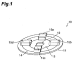
- Fig. 1 is a perspective view for explaining a configuration of a noise filter according to an embodiment of the present invention.
- Fig. 2 is a schematic diagram for explaining a configuration of a motor according to an embodiment of the present invention.
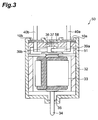
- Fig. 3 is a schematic diagram for explaining a configuration of a motor according to an embodiment of the present invention.
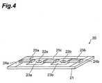
- Fig. 4 is a perspective view for explaining a configuration of a noise filter according to an embodiment of the present invention.
- Fig. 1 is a perspective view for explaining the configuration of noise filter 10.
- the noise filter 10 comprises a substrate 11 formed with a through hole 12, and a plurality of (four in the present embodiment) capacitors 15a-15d.
- the substrate 11 has a first conductor pattern 13 and a second conductor pattern 14.
- the capacitors 15a-15d can be multilayer chip capacitors.
- the substrate 11 is a printed circuit board of disk shape, in which the through hole 12 for letting a power supply line of a motor pass is formed in the center.
- the through hole 12 preferably has a size enough to let the power supply line pass and a shape similar to a sectional shape of the power supply line.
- the first conductor pattern 13 is located near the through hole 12 and is arranged on a concentric circle so as to surround the through hole 12.
- the second conductor pattern 14 is electrically insulated from the first conductor pattern 13 and is arranged on a concentric circle so as to surround the first conductor pattern 13.
- the outer periphery of the second conductor pattern 14 is approximately coincident with the outer periphery of the substrate 11.
- Each of the capacitors 15a-15d is arranged on the substrate 11 and is connected in series between the first conductor pattern 13 and the second conductor pattern 14.
- the capacitors 15a-15d are arranged so as to surround the through hole 12 on the substrate 11.
- Fig. 2 is a schematic diagram for explaining a configuration of a motor according to an embodiment of the present invention.
- the motor 30 comprises two noise filters 10a, 10b.
- the configuration of each noise filter 10a, 10b is the same as the above-described noise filter 10, and the description is thus omitted herein about the configuration of the noise filters 10a, 10b.
- the motor 30 has a housing 31 formed in a bottomed hollow cylindrical shape. Magnets 32 are attached to an inner peripheral surface of housing 31. Armature 33 is arranged so as to face the magnets 32. A rotor is composed of armature 33, shaft 34, and commutator 37. Bearing 35 fixed to the bottom of housing 31 and bearing 36 fixed to end bracket 38 in the top part of housing 31 rotatably support the shaft 34 forming the rotor. Brush 39a and brush 39b are mounted so as to be kept in sliding contact with the commutator 37. The brush 39a and the brush 39b are electrically connected to power supply lines 40a and 40b, respectively.
- the power supply line 40a and the power supply line 40b pass through the respective through holes 12 of the noise filter 10a and the noise filter 10b.
- the first conductor patterns 13 of the respective noise filters 10a and 10b are electrically connected to the power supply line 40a and to the power supply line 40b, respectively.
- the electric connections between the power supply lines 40a, 40b and the first conductor patterns 13 can be implemented by soldering, bonding with an electroconductive adhesive, or the like.
- the second conductor patterns 14 of the respective noise filters 10a and 10b are electrically connected to each other through a part of their side face in contact with the housing 31.
- the noise filter 10a and the noise filter 10b are fixed as bonded in and to grooves formed in the top surface of the end bracket 38.
- the top surface of noise filter 10 is located at the same height as the upper end of housing 31 and the upper face of the end bracket 38.
- the housing 31 and the second conductor patterns 14 may be electrically connected by soldering, bonding with an electroconductive adhesive, or the like.
- the first conductor pattern 13 to which the capacitors 15a-15d are electrically connected is formed near the through hole 12 for the power supply line 40a or 40b to pass, on the substrate 11, and thus the length of wires for electrically connecting the capacitors 15a-15d to the power supply line 40a or 40b is extremely short.
- the wires have the least influence of their inductance component and resistance component, so as to suppress the change in the frequency characteristic of the noise filter due to the inductance component and resistance component. Therefore, it is feasible to achieve a high noise removing effect of noise filter 10.
- first conductor pattern 13 and the second conductor pattern 14 are arranged on concentric circles so as to surround the through hole 12. This permits the four capacitors 15a-15d to be located in compact arrangement, so as to achieve miniaturization of the noise filter 10.
- the foregoing embodiments adopt four capacitors 15a-15d, but the number of capacitors 15a-15d can be set corresponding to the frequency of electric noise generated in the motor 30.
- Fig. 3 is a schematic diagram for explaining the configuration of motor 30.
- the motor 50 is different in the mount structure of noise filters 10a, 10b from the above-described motor 30.
- portions of housing 51 and end bracket 58 project to over the noise filters 10a, 10b to fix the noise filters 10a, 10b so as to keep them still in the vertical directions.
- the configuration except for this difference is the same as the configuration of the aforementioned motor 30, and the description thereof is thus omitted herein.
- Fig. 4 is a perspective view for explaining the configuration of noise filter 20 according to the present embodiment.
- the noise filter 20 is different from the aforementioned noise filter 10 in that the substrate is formed with two through holes, and has two sets of first conductor patterns and second conductor patterns.
- the noise filter 20 comprises a substrate 21 formed with two through holes, and a plurality of (three in the present embodiment) capacitors 25a-25c.
- the substrate 21 has a first set of first conductor pattern 23a and second conductor pattern 24a, and a second set of first conductor pattern 23b and second conductor pattern 24b.
- the capacitors 25a-25c can be multilayer chip capacitors.
- the substrate 21 is a printed circuit board of rectangular shape, and formed with circular through holes 22a and 22b for letting respective power supply lines of a motor pass.
- the first conductor pattern 23a and the first conductor pattern 23b are located near the through hole 22a and near the through hole 22b, respectively.
- the first conductor pattern 23a and the first conductor pattern 23b are arranged to surround the through hole 22a and the through hole 22b, respectively.
- the first conductor pattern 23a and the first conductor pattern 23b are square and the through hole 22a and the through hole 22b are located in the centers of the respective conductor patterns.
- the second conductor pattern 24a and the second conductor pattern 24b are electrically insulated from the first conductor pattern 23a and from the first conductor pattern 23b, respectively.
- the second conductor pattern 24a is formed in a rectangular shape at an end on the side near the first conductor pattern 23a on the substrate 21.
- the second conductor pattern 24b is formed in a rectangular shape at the end on the side near the first conductor pattern 23b on the substrate 21.
- Two sets of through holes 22a, 22b, first conductor patterns 23a, 23b, and second conductor patterns 24a, 24b are arranged in symmetry on the substrate 21.
- the capacitors 25a-25c are arranged on the substrate 21.
- the capacitor 25a is connected in series between the first conductor pattern 23a and the second conductor pattern 24a.
- the capacitor 25b is connected in series between the first conductor pattern 23b and the second conductor pattern 24b.
- the capacitor 25c is connected in series between the first conductor pattern 23a and the first conductor pattern 23b.
- the noise filter 20 of the present embodiment is also able to demonstrate a high noise removing effect as the aforementioned noise filter 10 was.
- the noise filter 20 adopts the common substrate 21 to two power supply lines, and each of the capacitors 25a-25c is connected to each power supply line. As a result, it becomes feasible to achieve miniaturization of the noise filter 20.
- the noise filter 20 has the capacitor 25c connected in series between the first conductor pattern 23a and the first conductor pattern 23b. This permits the capacitance of the noise filter 20 to be readily adjusted according to the frequency band of the generated electric noise, whereby the electric noise can be removed more effectively.
- each conductor pattern 13, 14, 23a, 23b, 24a, 24b, the number of capacitors 15a-15d, 25a-25c, etc. are not limited to those in each of the above-described embodiments.
Landscapes
- Engineering & Computer Science (AREA)
- Power Engineering (AREA)
- Physics & Mathematics (AREA)
- Electromagnetism (AREA)
- Dc Machiner (AREA)
- Motor Or Generator Frames (AREA)
- Shielding Devices Or Components To Electric Or Magnetic Fields (AREA)
Abstract
Description
- The present invention relates to a noise filter and a motor.
- In a DC motor, electric noise is generated by contact and separation operations between brushes and a commutator. A conventional means for removing the electric noise thus generated is to connect a capacitor to each power supply line of the DC motor and to make the capacitor function as a noise filter (e.g., reference is made to Japanese Patent Application Laid-Open No. 2001-268842).
- In the motor described in the Laid-Open No. 2001-268842, terminals for brush wiring functioning as power supply lines are extended from brush connection terminals and capacitors are connected to the extended portions of the terminals for brush wiring.
- In the motor described in the Laid-Open No. 2001-268842, the capacitors are connected to the extended portions of the terminals for brush wiring, and thus the distance is long between the capacitors and the portions of the terminals for brush wiring next to the brush connection terminals. Namely, the wires between the power supply lines and the capacitors are long in the motor described in the Laid-Open No. 2001-268842.
- Incidentally, the capacitors are selected so as to gain a frequency characteristic as noise filters, in view of the frequency band of the electric noise to be removed. However, as the wires become longer between the power supply lines and the capacitors, the wires come to demonstrate greater increase influence of their inductance component and resistance component, which will change the frequency characteristic as the noise filters. This will result in degrading the electric noise removing effect of the noise filters (capacitors).
- An object of the present invention is to provide a noise filter and a motor demonstrating an excellent effect of removing the electric noise.
- A noise filter according to the present invention comprises: a substrate formed with a through hole for letting a power supply line pass, and having a first conductor pattern located near the through hole and adapted to be electrically connected to the power supply line to pass through the through hole, and a second conductor pattern electrically insulated from the first conductor pattern; and a capacitor disposed on the substrate and connected in series between the first conductor pattern and the second conductor pattern.
- In the noise filter according to the present invention, the first conductor pattern to which the capacitor is electrically connected, and the through hole for the power supply line to pass are formed in vicinity to each other in the substrate, whereby the length of a wire for electrically connecting the capacitor to the power supply line becomes extremely short. For this reason, the wire has the least influence of its inductance component and resistance component, so as to suppress the change in the frequency characteristic of the noise filter due to the inductance component and resistance component. According to the present invention, therefore, the electric noise can be effectively removed.
- The noise filter according to the present invention preferably comprises a plurality of capacitors as described above. When the noise filter comprises the plurality of capacitors as in this configuration, the capacitance of the noise filter can be readily adjusted according to the frequency band of the generated electric noise. Therefore, the electric noise can be removed more effectively.
- In the noise filter according to the present invention, preferably, the first conductor pattern and the second conductor pattern are arranged on respective concentric circles so as to surround the through hole. This configuration permits the capacitor to be located in compact arrangement between the first conductor pattern and the second conductor pattern, so as to achieve miniaturization of the substrate.
- In the noise filter according to the present invention, preferably, the substrate is formed with two said through holes, and has two sets of first conductor patterns and second conductor patterns, and the capacitor comprises a capacitor connected in series between the first conductor pattern and the second conductor pattern in one set, and a capacitor connected in series between the first conductor pattern and the second conductor pattern in the other set. In this case, the common substrate is used for two power supply lines, whereby the capacitors are connected to the respective power supply lines. In consequence, it becomes feasible to achieve miniaturization of the noise filter.
- In the noise filter according to the present invention, preferably, the capacitor further comprises a capacitor connected in series between the first conductor pattern in the one set and the first conductor pattern in the other set. In this case, the capacitance of the noise filter can be readily adjusted according to the frequency band of the generated electric noise, whereby the electric noise can be removed more effectively.
- A motor according to the present invention comprises the above-described noise filter.
- Since the motor according to the present invention comprises the noise filter, the electric noise generated therein can be effectively removed.
- The present invention successfully provides the noise filter and motor demonstrating the excellent effect of removing the electric noise.
- Fig. 1 is a perspective view for explaining a configuration of a noise filter according to an embodiment of the present invention.
- Fig. 2 is a schematic diagram for explaining a configuration of a motor according to an embodiment of the present invention.
- Fig. 3 is a schematic diagram for explaining a configuration of a motor according to an embodiment of the present invention.
- Fig. 4 is a perspective view for explaining a configuration of a noise filter according to an embodiment of the present invention.
- Noise filters and motors according to embodiments of the present invention will be described with reference to the drawings. Identical elements, or elements with identical functionality will be denoted by the same reference symbols throughout the description, without redundant description. It is noted that the terms indicating the directions such as the top, bottom, left, and right are based on the drawings and provided for descriptive purposes only.
- First,
noise filter 10 according to an embodiment of the present invention will be described with reference to Fig. 1. Fig. 1 is a perspective view for explaining the configuration ofnoise filter 10. Thenoise filter 10 comprises asubstrate 11 formed with athrough hole 12, and a plurality of (four in the present embodiment)capacitors 15a-15d. Thesubstrate 11 has afirst conductor pattern 13 and asecond conductor pattern 14. Thecapacitors 15a-15d can be multilayer chip capacitors. - The
substrate 11 is a printed circuit board of disk shape, in which thethrough hole 12 for letting a power supply line of a motor pass is formed in the center. The throughhole 12 preferably has a size enough to let the power supply line pass and a shape similar to a sectional shape of the power supply line. Thefirst conductor pattern 13 is located near the throughhole 12 and is arranged on a concentric circle so as to surround the throughhole 12. Thesecond conductor pattern 14 is electrically insulated from thefirst conductor pattern 13 and is arranged on a concentric circle so as to surround thefirst conductor pattern 13. The outer periphery of thesecond conductor pattern 14 is approximately coincident with the outer periphery of thesubstrate 11. - Each of the
capacitors 15a-15d is arranged on thesubstrate 11 and is connected in series between thefirst conductor pattern 13 and thesecond conductor pattern 14. Thecapacitors 15a-15d are arranged so as to surround the throughhole 12 on thesubstrate 11. -
Motor 30 according to an embodiment of the present invention will be described with reference to Fig. 2. Fig. 2 is a schematic diagram for explaining a configuration of a motor according to an embodiment of the present invention. Themotor 30 comprises twonoise filters noise filter noise filter 10, and the description is thus omitted herein about the configuration of thenoise filters - The
motor 30 has ahousing 31 formed in a bottomed hollow cylindrical shape.Magnets 32 are attached to an inner peripheral surface ofhousing 31.Armature 33 is arranged so as to face themagnets 32. A rotor is composed ofarmature 33,shaft 34, andcommutator 37. Bearing 35 fixed to the bottom ofhousing 31 and bearing 36 fixed toend bracket 38 in the top part ofhousing 31 rotatably support theshaft 34 forming the rotor. Brush 39a andbrush 39b are mounted so as to be kept in sliding contact with thecommutator 37. Thebrush 39a and thebrush 39b are electrically connected topower supply lines - The
power supply line 40a and thepower supply line 40b pass through the respective throughholes 12 of thenoise filter 10a and thenoise filter 10b. Thefirst conductor patterns 13 of therespective noise filters power supply line 40a and to thepower supply line 40b, respectively. The electric connections between thepower supply lines first conductor patterns 13 can be implemented by soldering, bonding with an electroconductive adhesive, or the like. - The
second conductor patterns 14 of therespective noise filters housing 31. Thenoise filter 10a and thenoise filter 10b are fixed as bonded in and to grooves formed in the top surface of theend bracket 38. The top surface ofnoise filter 10 is located at the same height as the upper end ofhousing 31 and the upper face of theend bracket 38. Thehousing 31 and thesecond conductor patterns 14 may be electrically connected by soldering, bonding with an electroconductive adhesive, or the like. - Subsequently, the effect of the above embodiments will be described below.
- In the noise filters 10 (10a, 10b), the
first conductor pattern 13 to which thecapacitors 15a-15d are electrically connected is formed near the throughhole 12 for thepower supply line substrate 11, and thus the length of wires for electrically connecting thecapacitors 15a-15d to thepower supply line noise filter 10. - In addition, the
first conductor pattern 13 and thesecond conductor pattern 14 are arranged on concentric circles so as to surround the throughhole 12. This permits the fourcapacitors 15a-15d to be located in compact arrangement, so as to achieve miniaturization of thenoise filter 10. The foregoing embodiments adopt fourcapacitors 15a-15d, but the number ofcapacitors 15a-15d can be set corresponding to the frequency of electric noise generated in themotor 30. - Next, another
motor 50 according to an embodiment of the present invention will be described with reference to Fig. 3. Fig. 3 is a schematic diagram for explaining the configuration ofmotor 30. Themotor 50 is different in the mount structure ofnoise filters motor 30. - In the
motor 50, portions ofhousing 51 andend bracket 58 project to over thenoise filters noise filters aforementioned motor 30, and the description thereof is thus omitted herein. - Another noise filter according to an embodiment of the present invention will be described with reference to Fig. 4. Fig. 4 is a perspective view for explaining the configuration of
noise filter 20 according to the present embodiment. Thenoise filter 20 is different from theaforementioned noise filter 10 in that the substrate is formed with two through holes, and has two sets of first conductor patterns and second conductor patterns. - The
noise filter 20 comprises asubstrate 21 formed with two through holes, and a plurality of (three in the present embodiment)capacitors 25a-25c. Thesubstrate 21 has a first set offirst conductor pattern 23a andsecond conductor pattern 24a, and a second set offirst conductor pattern 23b andsecond conductor pattern 24b. Thecapacitors 25a-25c can be multilayer chip capacitors. - The
substrate 21 is a printed circuit board of rectangular shape, and formed with circular throughholes first conductor pattern 23a and thefirst conductor pattern 23b are located near the throughhole 22a and near the throughhole 22b, respectively. Thefirst conductor pattern 23a and thefirst conductor pattern 23b are arranged to surround the throughhole 22a and the throughhole 22b, respectively. Thefirst conductor pattern 23a and thefirst conductor pattern 23b are square and the throughhole 22a and the throughhole 22b are located in the centers of the respective conductor patterns. - The
second conductor pattern 24a and thesecond conductor pattern 24b are electrically insulated from thefirst conductor pattern 23a and from thefirst conductor pattern 23b, respectively. Thesecond conductor pattern 24a is formed in a rectangular shape at an end on the side near thefirst conductor pattern 23a on thesubstrate 21. Thesecond conductor pattern 24b is formed in a rectangular shape at the end on the side near thefirst conductor pattern 23b on thesubstrate 21. Two sets of throughholes first conductor patterns second conductor patterns substrate 21. - The
capacitors 25a-25c are arranged on thesubstrate 21. Thecapacitor 25a is connected in series between thefirst conductor pattern 23a and thesecond conductor pattern 24a. Thecapacitor 25b is connected in series between thefirst conductor pattern 23b and thesecond conductor pattern 24b. Thecapacitor 25c is connected in series between thefirst conductor pattern 23a and thefirst conductor pattern 23b. - The
noise filter 20 of the present embodiment is also able to demonstrate a high noise removing effect as theaforementioned noise filter 10 was. Thenoise filter 20 adopts thecommon substrate 21 to two power supply lines, and each of thecapacitors 25a-25c is connected to each power supply line. As a result, it becomes feasible to achieve miniaturization of thenoise filter 20. - The
noise filter 20 has thecapacitor 25c connected in series between thefirst conductor pattern 23a and thefirst conductor pattern 23b. This permits the capacitance of thenoise filter 20 to be readily adjusted according to the frequency band of the generated electric noise, whereby the electric noise can be removed more effectively. - The above described the preferred embodiments of the present invention, but it is noted that the present invention is not always limited to these embodiments. For example, the shape of each
conductor pattern capacitors 15a-15d, 25a-25c, etc. are not limited to those in each of the above-described embodiments.
Claims (12)
- A noise filter comprising:a substrate formed with a through hole for letting a power supply line pass; anda capacitor placed on the substrate,wherein the substrate has:a first conductor pattern located near the through hole and adapted to be electrically connected to the power supply line to pass through the through hole, anda second conductor pattern electrically insulated from the first conductor pattern; andwherein the capacitor is connected in series between the first conductor pattern and the second conductor pattern.
- The noise filter according to Claim 1, comprising a plurality of said capacitors.
- The noise filter according to Claim 1, wherein the first conductor pattern and the second conductor pattern are arranged on concentric circles so as to surround the through hole.
- The noise filter according to Claim 2, wherein the first conductor pattern and the second conductor pattern are arranged on concentric circles so as to surround the through hole.
- The noise filter according to Claim 1,
wherein the substrate is formed with two said through holes, and has two sets of said first conductor patterns and said second conductor patterns, and
wherein the capacitor comprises a capacitor connected in series between the first conductor pattern and the second conductor pattern in one set, and a capacitor connected in series between the first conductor pattern and the second conductor pattern in the other set. - The noise filter according to Claim 5, wherein the capacitor further comprises a capacitor connected in series between the first conductor pattern in the one set and the first conductor pattern in the other set.
- A motor comprising a noise filter,
wherein the noise filter comprises a substrate formed with a through hole for letting a power supply line pass, and a capacitor placed on the substrate,
wherein the substrate has:a first conductor pattern located near the through hole and adapted to be electrically connected to the power supply line to pass through the through hole, anda second conductor pattern electrically insulated from the first conductor pattern; andwherein the capacitor is connected in series between the first conductor pattern and the second conductor pattern. - The motor according to Claim 7, wherein the noise filter comprises a plurality of said capacitors.
- The motor according to Claim 7, wherein the first conductor pattern and the second conductor pattern are arranged on concentric circles so as to surround the through hole.
- The motor according to Claim 8, wherein the first conductor pattern and the second conductor pattern are arranged on concentric circles so as to surround the through hole.
- The motor according to Claim 7, wherein the noise filter is configured as follows:the substrate is formed with two said through holes, and has two sets of said first conductor patterns and said second conductor patterns, andthe capacitor comprises a capacitor connected in series between the first conductor pattern and the second conductor pattern in one set, and a capacitor connected in series between the first conductor pattern and the second conductor pattern in the other set.
- The motor according to Claim 11, wherein the noise filter is configured as follows: the capacitor further comprises a capacitor connected in series between the first conductor pattern in the one set and the first conductor pattern in the other set.
Applications Claiming Priority (1)
| Application Number | Priority Date | Filing Date | Title |
|---|---|---|---|
| JP2004344688A JP4157092B2 (en) | 2004-11-29 | 2004-11-29 | motor |
Publications (3)
| Publication Number | Publication Date |
|---|---|
| EP1670123A2 true EP1670123A2 (en) | 2006-06-14 |
| EP1670123A3 EP1670123A3 (en) | 2006-06-28 |
| EP1670123B1 EP1670123B1 (en) | 2011-03-23 |
Family
ID=36208195
Family Applications (1)
| Application Number | Title | Priority Date | Filing Date |
|---|---|---|---|
| EP05025266A Expired - Lifetime EP1670123B1 (en) | 2004-11-29 | 2005-11-18 | Noise filter and electric motor comprising this filter |
Country Status (7)
| Country | Link |
|---|---|
| US (1) | US20060113850A1 (en) |
| EP (1) | EP1670123B1 (en) |
| JP (1) | JP4157092B2 (en) |
| KR (1) | KR100791800B1 (en) |
| CN (1) | CN100448137C (en) |
| DE (1) | DE602005027039D1 (en) |
| TW (1) | TWI382633B (en) |
Cited By (3)
| Publication number | Priority date | Publication date | Assignee | Title |
|---|---|---|---|---|
| WO2008128838A1 (en) * | 2007-04-19 | 2008-10-30 | Robert Bosch Gmbh | Dc motor with a leadthrough capacitor |
| WO2010076071A1 (en) * | 2009-01-05 | 2010-07-08 | Robert Bosch Gmbh | Electric device, particularly control device |
| EP3945754A1 (en) * | 2020-07-30 | 2022-02-02 | Valeo Systèmes d'Essuyage | Contact retainer for an integrated circuit |
Families Citing this family (12)
| Publication number | Priority date | Publication date | Assignee | Title |
|---|---|---|---|---|
| CN102971946B (en) * | 2010-07-06 | 2016-03-16 | 三菱电机株式会社 | inverter |
| JP5768642B2 (en) * | 2011-10-04 | 2015-08-26 | 株式会社デンソー | Starter |
| FR2982911B1 (en) * | 2011-11-18 | 2013-11-15 | Valeo Equip Electr Moteur | ELECTRICAL STARTER WITH ELECTRONIC INTEGRATED FILTER FOR INTERNAL COMBUSTION ENGINE |
| DE112012002638T5 (en) * | 2012-04-18 | 2014-05-15 | Mitsubishi Electric Corporation | Noise filtering apparatus |
| KR102158263B1 (en) * | 2014-04-04 | 2020-09-21 | 엘지이노텍 주식회사 | Motor |
| JP6631868B2 (en) * | 2015-03-30 | 2020-01-15 | パナソニックIpマネジメント株式会社 | Leakage detection circuit |
| CN104953802A (en) * | 2015-06-16 | 2015-09-30 | 联合汽车电子有限公司 | Electromagnetic compatibility filter |
| JP2017055584A (en) * | 2015-09-10 | 2017-03-16 | ジョンソンコントロールズ ヒタチ エア コンディショニング テクノロジー(ホンコン)リミテッド | Three-phase noise filter and ac motor driving system using the same |
| KR102511767B1 (en) * | 2016-01-25 | 2023-03-20 | 엘지이노텍 주식회사 | Cover assembly for motor motor and vehicle having the same |
| JP2017135163A (en) * | 2016-01-25 | 2017-08-03 | Tdk株式会社 | Electronic component |
| JP2019067896A (en) * | 2017-09-29 | 2019-04-25 | 日本電産エレシス株式会社 | Circuit board and control device |
| US12100560B2 (en) * | 2021-05-18 | 2024-09-24 | Ut-Battelle, Llc | High-performance capacitor packaging for next generation power electronics |
Citations (1)
| Publication number | Priority date | Publication date | Assignee | Title |
|---|---|---|---|---|
| JP2001268842A (en) | 2000-03-16 | 2001-09-28 | Asmo Co Ltd | Motor |
Family Cites Families (18)
| Publication number | Priority date | Publication date | Assignee | Title |
|---|---|---|---|---|
| JPS5915066Y2 (en) * | 1979-12-03 | 1984-05-04 | ティーディーケイ株式会社 | Feedthrough capacitor |
| US4329605A (en) * | 1980-10-14 | 1982-05-11 | General Motors Corporation | Electric motor having radio frequency interference radiation suppression |
| JPS5822569A (en) * | 1981-07-31 | 1983-02-09 | Matsushita Electric Works Ltd | Motor |
| JPH06268464A (en) * | 1993-03-17 | 1994-09-22 | Mitsubishi Materials Corp | Noise filter block |
| GB9423689D0 (en) * | 1994-11-24 | 1995-01-11 | Johnson Electric Sa | A rotor for an electric motor |
| US5650759A (en) * | 1995-11-09 | 1997-07-22 | Hittman Materials & Medical Components, Inc. | Filtered feedthrough assembly having a mounted chip capacitor for medical implantable devices and method of manufacture therefor |
| US5896267A (en) * | 1997-07-10 | 1999-04-20 | Greatbatch-Hittman, Inc. | Substrate mounted filter for feedthrough devices |
| US5959829A (en) * | 1998-02-18 | 1999-09-28 | Maxwell Energy Products, Inc. | Chip capacitor electromagnetic interference filter |
| US5973906A (en) * | 1998-03-17 | 1999-10-26 | Maxwell Energy Products, Inc. | Chip capacitors and chip capacitor electromagnetic interference filters |
| JP3803258B2 (en) * | 2000-04-03 | 2006-08-02 | Tdk株式会社 | High-voltage feedthrough capacitor and magnetron |
| DE10119404A1 (en) * | 2001-04-20 | 2002-10-24 | Bosch Gmbh Robert | Electronically commutated dc motor e.g. for cooling water pump in vehicle, has grid stamping for providing all connections to electronic system |
| US20020167237A1 (en) * | 2001-05-10 | 2002-11-14 | Sunonwealth Electric Machine Industry Co., Ltd | Fixing structure of a miniature vibration motor |
| JP2003037961A (en) * | 2001-07-25 | 2003-02-07 | Yoshiyuki Mori | Small size motor |
| JP2003116247A (en) * | 2001-10-04 | 2003-04-18 | Mabuchi Motor Co Ltd | Miniature motor and method of manufacturing the same |
| DE10224221A1 (en) * | 2002-05-31 | 2003-12-11 | Siemens Ag | Electrical device |
| US7295086B2 (en) * | 2002-10-23 | 2007-11-13 | Spectrum Control Inc. | Dielectric component array with failsafe link |
| EP1503484A3 (en) * | 2003-07-23 | 2006-03-15 | Sintertechnik GmbH | Arrangement for interference suppression in electric motors |
| KR100591309B1 (en) * | 2003-12-30 | 2006-06-19 | 엘지전자 주식회사 | High Pressure Capacitors for Magnetrons |
-
2004
- 2004-11-29 JP JP2004344688A patent/JP4157092B2/en not_active Expired - Fee Related
-
2005
- 2005-11-11 KR KR1020050107818A patent/KR100791800B1/en not_active Expired - Fee Related
- 2005-11-18 TW TW094140728A patent/TWI382633B/en not_active IP Right Cessation
- 2005-11-18 DE DE602005027039T patent/DE602005027039D1/en not_active Expired - Lifetime
- 2005-11-18 EP EP05025266A patent/EP1670123B1/en not_active Expired - Lifetime
- 2005-11-18 US US11/281,556 patent/US20060113850A1/en not_active Abandoned
- 2005-11-29 CN CNB2005101243868A patent/CN100448137C/en not_active Expired - Fee Related
Patent Citations (1)
| Publication number | Priority date | Publication date | Assignee | Title |
|---|---|---|---|---|
| JP2001268842A (en) | 2000-03-16 | 2001-09-28 | Asmo Co Ltd | Motor |
Cited By (4)
| Publication number | Priority date | Publication date | Assignee | Title |
|---|---|---|---|---|
| WO2008128838A1 (en) * | 2007-04-19 | 2008-10-30 | Robert Bosch Gmbh | Dc motor with a leadthrough capacitor |
| US8378538B2 (en) | 2007-04-19 | 2013-02-19 | Robert Bosch Gmbh | DC motor with a leadthrough capacitor |
| WO2010076071A1 (en) * | 2009-01-05 | 2010-07-08 | Robert Bosch Gmbh | Electric device, particularly control device |
| EP3945754A1 (en) * | 2020-07-30 | 2022-02-02 | Valeo Systèmes d'Essuyage | Contact retainer for an integrated circuit |
Also Published As
| Publication number | Publication date |
|---|---|
| KR20060059811A (en) | 2006-06-02 |
| CN1783666A (en) | 2006-06-07 |
| KR100791800B1 (en) | 2008-01-04 |
| TWI382633B (en) | 2013-01-11 |
| CN100448137C (en) | 2008-12-31 |
| EP1670123A3 (en) | 2006-06-28 |
| EP1670123B1 (en) | 2011-03-23 |
| TW200633344A (en) | 2006-09-16 |
| JP2006158086A (en) | 2006-06-15 |
| JP4157092B2 (en) | 2008-09-24 |
| DE602005027039D1 (en) | 2011-05-05 |
| US20060113850A1 (en) | 2006-06-01 |
Similar Documents
| Publication | Publication Date | Title |
|---|---|---|
| EP1670123B1 (en) | Noise filter and electric motor comprising this filter | |
| CN102439826B (en) | Rfi suppression system and method of mounting for DC cordless tools | |
| JP2020057788A (en) | Printed circuit board and motor including the same | |
| JP6278994B2 (en) | Power filter | |
| JP5494586B2 (en) | Voltage conversion module | |
| JPH03183106A (en) | Printed wiring board | |
| JP2010525778A (en) | Electric motor | |
| KR100355753B1 (en) | Board to board connector | |
| JP4501145B2 (en) | Three-phase noise filter | |
| JP2006245618A (en) | Passive element built-in semiconductor device | |
| US7709929B2 (en) | Capacitor sheet and electronic circuit board | |
| WO2007123038A1 (en) | Electret capacitor microphone | |
| JPH01216591A (en) | Printed board | |
| KR100514314B1 (en) | Surface maunting type electronic circuit unit | |
| JPS6311772Y2 (en) | ||
| JP2001167974A (en) | Circuit board and circuit module using the same and electronic device using the module | |
| JP4985852B2 (en) | Mounted electronic circuit module | |
| JPS61251017A (en) | Composite part | |
| JP6610072B2 (en) | Multilayer capacitor and wiring board | |
| JPH05234643A (en) | Counter-noise type connector and noise removing parts for counter-noise type connector | |
| JPH0229715Y2 (en) | ||
| JP2574176Y2 (en) | Circuit component mounting structure | |
| JPS6233299Y2 (en) | ||
| JPH07202374A (en) | Printed circuit board pattern | |
| JP2002374049A (en) | Mounting structure for power-supply device |
Legal Events
| Date | Code | Title | Description |
|---|---|---|---|
| PUAI | Public reference made under article 153(3) epc to a published international application that has entered the european phase |
Free format text: ORIGINAL CODE: 0009012 |
|
| PUAL | Search report despatched |
Free format text: ORIGINAL CODE: 0009013 |
|
| AK | Designated contracting states |
Kind code of ref document: A2 Designated state(s): AT BE BG CH CY CZ DE DK EE ES FI FR GB GR HU IE IS IT LI LT LU LV MC NL PL PT RO SE SI SK TR |
|
| AX | Request for extension of the european patent |
Extension state: AL BA HR MK YU |
|
| AK | Designated contracting states |
Kind code of ref document: A3 Designated state(s): AT BE BG CH CY CZ DE DK EE ES FI FR GB GR HU IE IS IT LI LT LU LV MC NL PL PT RO SE SI SK TR |
|
| AX | Request for extension of the european patent |
Extension state: AL BA HR MK YU |
|
| 17P | Request for examination filed |
Effective date: 20060830 |
|
| 17Q | First examination report despatched |
Effective date: 20061011 |
|
| AKX | Designation fees paid |
Designated state(s): DE FR GB |
|
| 17Q | First examination report despatched |
Effective date: 20061011 |
|
| GRAP | Despatch of communication of intention to grant a patent |
Free format text: ORIGINAL CODE: EPIDOSNIGR1 |
|
| GRAS | Grant fee paid |
Free format text: ORIGINAL CODE: EPIDOSNIGR3 |
|
| GRAA | (expected) grant |
Free format text: ORIGINAL CODE: 0009210 |
|
| AK | Designated contracting states |
Kind code of ref document: B1 Designated state(s): DE FR GB |
|
| REG | Reference to a national code |
Ref country code: GB Ref legal event code: FG4D |
|
| REF | Corresponds to: |
Ref document number: 602005027039 Country of ref document: DE Date of ref document: 20110505 Kind code of ref document: P |
|
| REG | Reference to a national code |
Ref country code: DE Ref legal event code: R096 Ref document number: 602005027039 Country of ref document: DE Effective date: 20110505 |
|
| PLBE | No opposition filed within time limit |
Free format text: ORIGINAL CODE: 0009261 |
|
| STAA | Information on the status of an ep patent application or granted ep patent |
Free format text: STATUS: NO OPPOSITION FILED WITHIN TIME LIMIT |
|
| PGFP | Annual fee paid to national office [announced via postgrant information from national office to epo] |
Ref country code: FR Payment date: 20111130 Year of fee payment: 7 |
|
| 26N | No opposition filed |
Effective date: 20111227 |
|
| REG | Reference to a national code |
Ref country code: DE Ref legal event code: R097 Ref document number: 602005027039 Country of ref document: DE Effective date: 20111227 |
|
| GBPC | Gb: european patent ceased through non-payment of renewal fee |
Effective date: 20121118 |
|
| REG | Reference to a national code |
Ref country code: FR Ref legal event code: ST Effective date: 20130731 |
|
| PG25 | Lapsed in a contracting state [announced via postgrant information from national office to epo] |
Ref country code: GB Free format text: LAPSE BECAUSE OF NON-PAYMENT OF DUE FEES Effective date: 20121118 Ref country code: FR Free format text: LAPSE BECAUSE OF NON-PAYMENT OF DUE FEES Effective date: 20121130 |
|
| PGFP | Annual fee paid to national office [announced via postgrant information from national office to epo] |
Ref country code: DE Payment date: 20131113 Year of fee payment: 9 |
|
| REG | Reference to a national code |
Ref country code: DE Ref legal event code: R119 Ref document number: 602005027039 Country of ref document: DE |
|
| PG25 | Lapsed in a contracting state [announced via postgrant information from national office to epo] |
Ref country code: DE Free format text: LAPSE BECAUSE OF NON-PAYMENT OF DUE FEES Effective date: 20150602 |