EP1669960A1 - Melder mit Kommunikationsantenne - Google Patents
Melder mit Kommunikationsantenne Download PDFInfo
- Publication number
- EP1669960A1 EP1669960A1 EP04029040A EP04029040A EP1669960A1 EP 1669960 A1 EP1669960 A1 EP 1669960A1 EP 04029040 A EP04029040 A EP 04029040A EP 04029040 A EP04029040 A EP 04029040A EP 1669960 A1 EP1669960 A1 EP 1669960A1
- Authority
- EP
- European Patent Office
- Prior art keywords
- communication antenna
- fastening means
- housing
- detector
- hazard detector
- Prior art date
- Legal status (The legal status is an assumption and is not a legal conclusion. Google has not performed a legal analysis and makes no representation as to the accuracy of the status listed.)
- Withdrawn
Links
Images
Classifications
-
- G—PHYSICS
- G08—SIGNALLING
- G08B—SIGNALLING SYSTEMS, e.g. PERSONAL CALLING SYSTEMS; ORDER TELEGRAPHS; ALARM SYSTEMS
- G08B25/00—Alarm systems in which the location of the alarm condition is signalled to a central station, e.g. fire or police telegraphic systems
- G08B25/01—Alarm systems in which the location of the alarm condition is signalled to a central station, e.g. fire or police telegraphic systems characterised by the transmission medium
- G08B25/10—Alarm systems in which the location of the alarm condition is signalled to a central station, e.g. fire or police telegraphic systems characterised by the transmission medium using wireless transmission systems
-
- G—PHYSICS
- G08—SIGNALLING
- G08B—SIGNALLING SYSTEMS, e.g. PERSONAL CALLING SYSTEMS; ORDER TELEGRAPHS; ALARM SYSTEMS
- G08B21/00—Alarms responsive to a single specified undesired or abnormal condition and not otherwise provided for
- G08B21/02—Alarms for ensuring the safety of persons
- G08B21/0202—Child monitoring systems using a transmitter-receiver system carried by the parent and the child
- G08B21/0291—Housing and user interface of child unit
-
- H—ELECTRICITY
- H01—ELECTRIC ELEMENTS
- H01Q—ANTENNAS, i.e. RADIO AERIALS
- H01Q1/00—Details of, or arrangements associated with, antennas
- H01Q1/12—Supports; Mounting means
- H01Q1/22—Supports; Mounting means by structural association with other equipment or articles
-
- G—PHYSICS
- G08—SIGNALLING
- G08B—SIGNALLING SYSTEMS, e.g. PERSONAL CALLING SYSTEMS; ORDER TELEGRAPHS; ALARM SYSTEMS
- G08B17/00—Fire alarms; Alarms responsive to explosion
-
- G—PHYSICS
- G08—SIGNALLING
- G08B—SIGNALLING SYSTEMS, e.g. PERSONAL CALLING SYSTEMS; ORDER TELEGRAPHS; ALARM SYSTEMS
- G08B17/00—Fire alarms; Alarms responsive to explosion
- G08B17/10—Actuation by presence of smoke or gases, e.g. automatic alarm devices for analysing flowing fluid materials by the use of optical means
- G08B17/11—Actuation by presence of smoke or gases, e.g. automatic alarm devices for analysing flowing fluid materials by the use of optical means using an ionisation chamber for detecting smoke or gas
- G08B17/113—Constructional details
Definitions
- the present invention relates to a fastening means for a wireless local area network communication antenna to be mounted in a room.
- Such communication antennas are installed today, for example, in a hemispherical housing, which is attached to the relevant space as completely covering point so that, for example, at each point of the room optimal transmission and reception conditions for wireless communication with appropriately equipped devices in the room are given.
- the most suitable point is the center of the ceiling of the room.
- the housing containing the communication antenna is often perceived as aesthetically unsatisfactory and there are also people who classify this housing as a source of radiation for electrosmog and rather not like to stay in the room in question.
- the invention will now be a fastener for communication antennas of the type mentioned above, which is rather not registered by the people staying in the room.
- fastening means is formed by an existing in the ceiling or wall area of the room lighting or surveillance installation.
- Lighting installations can be wall or ceiling luminaires and, in particular, so-called luminaire canopies, and above all, danger detectors such as fire, gas or motion detectors, presence detectors or cameras are suitable monitoring installations.
- Fire detectors and lighting canopies are particularly well suited because they are usually located in the middle of the ceiling. Since they are also wired, the combination of the two completely alien products, communication antenna on the one hand and lighting or surveillance installation on the other hand, at least in the installation costs will result in a reduction.
- a first preferred embodiment of the inventive fastening means is characterized in that the fastening means formed by aumpssbaldachin and the communication antenna is installed in this or attached thereto.
- the fastening means is formed by a hazard detector in the manner of a fire, gas or motion detector.
- the fastening means is formed by a presence detector.
- the fastening means is formed by a surveillance camera.
- the invention further relates to a hazard detector comprising a housing, a sensor arrangement, an evaluation electronics and a base provided for holding the housing.
- a first preferred embodiment of the inventive hazard detector is characterized in that the communication antenna is mounted on a plate arranged in the housing and acting as a grounding plate.
- the communication antenna is arranged on a part of the transmitter forming or supporting this printed circuit board.
- a third preferred embodiment of the inventive hazard detector is characterized in that the communication antenna is adapted to the contour of the housing or the base.
- the communication antenna is integrated in the wall of the housing or the base or is applied to this.
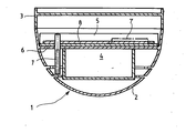
- FIG. 1 shows a schematic section through a smoke detector.
- the illustrated smoke detector 1 which is for example a scattered light smoke detector of the type described in the documents EP-A-0 616 305, EP-A-0 821 330 or EP-A-1 376 504, consists, as shown, of a housing 2 and a holder
- the housing contains inter alia a sensor unit 4 for the detection of smoke and an evaluation 5 for the processing and evaluation of the signals of the sensor unit 4.
- the evaluation 5 includes, inter alia, a circuit board 6, on which the entire evaluation 5 or at least substantial parts of this are arranged.
- the base 3 is not only used for mechanical support of the housing 2, but it also contains the necessary electrical connections for the power supply of the smoke detector and for its communication with other smoke detectors and a central office. Of course, this communication can also be wireless via radio.
- a rod-shaped communication antenna 7 is provided in the housing 2, which is attached to an acting as a soil plate 8, which is for example supported by the circuit board 6.
- the communication antenna 7 serves to allow optimum transmission and reception conditions for wireless communication in the relevant room with appropriately equipped devices, such as radio telephones or computers of a wireless local area network (WLAN).
- the communication antenna 7 extends from the plate 8 laterally next to the sensor system 4 down so that it does not affect the spreading conditions in the smoke detector 1.
- a thermal fire detector which contains only a heat-sensitive sensor but no optical sensor elements, there is a greater freedom with respect to the arrangement of the communication antenna 7 in the housing. 2
- the plate 8 with the communication antenna 7 may be arranged instead of the housing 2 in the base 3 of the smoke detector 1.
- the housing 2 is locked by a rotational movement of about 90 ° or less in the base 3, in this type of attachment of the communication antenna 7 in the smoke detector 1 make sure that the plate 7 with the communication antenna 7 either way in the Socket 3 is held that it is able to follow the rotational movement when turning in and out of the housing 2, or that the communication antenna 7 is arranged and / or the sensor system 4 is formed so that the communication antenna 7 can be pivoted past the sensor system 4.
- the communication antenna 7 may instead be mounted directly on the printed circuit board 6 on the wafer 8, wherein of course the shape of the communication antenna 7 is variable within wide limits.
- the antenna need not have the illustrated shape of a tube, but may also be designed as a narrow, graded from the circuit board 6 and with both ends attached to this ribbon 7 '.
- Another possibility of forming the communication antenna 7 is not to let them project vertically downwards, but to adapt the contour of the housing 2 or the base 3 or to integrate them in the wall of the housing 2 or the base 3 or to apply to these ,
- the illustrated embodiment with the attachment of the communication antenna 7 in a fire alarm is not intended to be limiting.
- the communication antenna can be mounted analogously in any ceiling detector, for example presence detector or dome camera, or in a wall detector, such as motion detectors or gas detectors.
- Other suitable attachment means for the communication antenna 7 are lighting installations, such as wall or ceiling lights or in particular also lighting canopy.
Landscapes
- Health & Medical Sciences (AREA)
- Engineering & Computer Science (AREA)
- Child & Adolescent Psychology (AREA)
- General Health & Medical Sciences (AREA)
- Business, Economics & Management (AREA)
- Emergency Management (AREA)
- Physics & Mathematics (AREA)
- General Physics & Mathematics (AREA)
- Human Computer Interaction (AREA)
- Computer Networks & Wireless Communication (AREA)
- Fire Alarms (AREA)
Abstract
Ein Befestigungsmittel für eine in einem Raum zu montierende Kommunikationsantenne (7, 7') eines drahtlosen lokalen Netzwerks ist durch eine im Decken- oder Wandbereich des Raums vorhandene Beleuchtungs- oder Überwachungsinstallation gebildet, in welche die Kommunikationsantenne (7, 7') eingebaut oder an welcher sie befestigt ist. Das Befestigungsmittel ist durch einen Beleuchtungsbaldachin oder durch einen Gefahrenmelder (1) in der Art eines Brand-, Gas- oder Bewegungsmelders gebildet.
Ein Gefahrenmelder (1) enthält ein Gehäuse (2), eine Sensoranordnung (4), eine Auswerteelektronik (5) und einen zur Halterung des Gehäuses (2) vorgesehenen Sockel (3). In das Gehäuse (2) oder in den Sockel (3) ist eine Kommunikationsantenne (7, 7') eingebaut.
Description
- Die vorliegende Erfindung betrifft ein Befestigungsmittel für eine in einem Raum zu montierende Kommunikationsantenne eines drahtlosen lokalen Netzwerks.
- Derartige Kommunikationsantennen werden heute beispielsweise in ein halbkugelförmiges Gehäuse eingebaut, welches an einem den betreffenden Raum möglichst vollständig abdeckenden Punkt befestigt wird, damit beispielsweise an jedem Punkt des Raums optimale Sende- und Empfangsverhältnisse für drahtlose Kommunikation mit entsprechend ausgerüsteten Geräten in dem betreffenden Raum gegeben sind. Dabei ist der am besten geeignete Punkt die Mitte der Decke des Raums. Allerdings wird das die Kommunikationsantenne enthaltende Gehäuse vielfach als ästhetisch unbefriedigend empfunden und es gibt ausserdem Menschen, die dieses Gehäuse als Strahlungsquelle für Elektrosmog einstufen und sich eher nicht gerne in dem betreffenden Raum aufhalten.
- Durch die Erfindung soll nun ein Befestigungsmittel für Kommunikationsantennen der eingangs genannten Art angegeben werden, welches von den sich im Raum aufhaltenden Menschen eher nicht registriert wird.
- Diese Aufgabe wird erfindungsgemäss dadurch gelöst, dass das Befestigungsmittel durch eine im Decken- oder Wandbereich des Raums vorhandene Beleuchtungs- oder Überwachungsinstallation gebildet ist.
- Die Begriffe Beleuchtungs- und Überwachungsinstallation sind weit zu verstehen. Bei Beleuchtungsinstallationen kann es sich um Wand- oder Deckenleuchten und insbesondere um so genannte Leuchtenbaldachine handeln, und als geeignete Überwachungsinstallation kommen vor allen Dingen Gefahrenmelder, wie Brand-, Gas- oder Bewegungsmelder, Präsenzmelder oder Kameras in Frage. Brandmelder und Beleuchtungsbaldachine sind besonders gut geeignet, weil sie zumeist in der Mitte der Decke angeordnet sind. Da sie ausserdem verkabelt sind, wird sich durch die Kombination der beiden völlig gattungsfremden Produkte, Kommunikationsantenne einerseits und Beleuchtungs- oder Überwachungsinstallation andererseits, zumindest bei den Installationskosten eine Reduktion ergeben.
- Eine erste bevorzugte Ausführungsform der erfindungsgemässen Befestigungsmittel ist dadurch gekennzeichnet, dass das Befestigungsmittel durch einen Beleuchtungsbaldachin gebildet und die Kommunikationsantenne in dieses eingebaut oder an diesem befestigt ist.
- Gemäss einer zweiten bevorzugten Ausführungsform ist das Befestigungsmittel durch einen Gefahrenmelder in der Art eines Brand-, Gas- oder Bewegungsmelders gebildet.
- Gemäss einer dritten bevorzugten Ausführungsform ist das Befestigungsmittel durch einen Präsenzmelder gebildet.
- Gemäss einer vierten bevorzugten Ausführungsform ist das Befestigungsmittel durch eine Überwachungskamera gebildet.
- Die Erfindung betrifft weiter einen Gefahrenmelder mit einem Gehäuse, einer Sensoranordnung, einer Auswerteelektronik und einem zur Halterung des Gehäuses vorgesehenen Sockel.
- Derartige Gefahrenmelder sind heute in der Form von Brand-, Bewegungs- oder Gasmeldern weit verbreitet, wobei Brandmelder in der Regel an der Decke und Bewegungsmelder an einer Wand des zu überwachenden Raums montiert sind. Diese Melder haben heute in vielen Fällen eine gefällige Formgebung und werden nicht als störend empfunden, insbesondere auch deswegen, weil sie das Sicherheitsgefühl der sich in dem betreffenden Raum befindlichen Personen verstärken.
- Durch die Erfindung sollen nun die bekannten Gefahrenmelder einer zusätzlichen Nutzung zugeführt.
- Diese Aufgabe wird erfindungsgemäss dadurch gelöst, dass in das Gehäuse oder in den Sockel eine Kommunikationsantenne eingebaut ist.
- Durch die erfindungsgemässe Kombination der beiden völlig gattungsfremden Produkte Gefahrenmelder einerseits und Kommunikationsantenne anderseits ergibt sich eine Reihe von Vorteilen: Durch den Einbau der Kommunikationsantenne in den Gefahrenmelder entfällt ein zusätzlicher und oftmals als störend empfundener Gegenstand an der Decke des zu überwachenden Raumes. Ausserdem wird man in den meisten Fällen eine zumindest teilweise gemeinsame Verkabelung benutzen können, was sich in einer Reduktion der Instaltationskosten niederschlagen sollte.
- Eine erste bevorzugte Ausführungsform des erfindungsgemässen Gefahrenmelders ist dadurch gekennzeichnet, dass die Kommunikationsantenne an einem im Gehäuse angeordneten und als Erdung wirkenden Plättchen befestigt ist.
- Gemäss einer zweiten bevorzugten Ausführungsform ist die Kommunikationsantenne auf einer Teil der Auswerteelektronik bildenden oder diese tragenden Leiterplatte angeordnet ist.
- Eine dritte bevorzugte Ausführungsform des erfindungsgemässen Gefahrenmelders ist dadurch gekennzeichnet, dass die Kommunikationsantenne an die Kontur des Gehäuses oder des Sockels angepasst ist.
- Gemäss einer vierten bevorzugten Ausführungsform ist die Kommunikationsantenne in die Wand des Gehäuses oder des Sockels integriert oder auf diese appliziert ist.
- Im folgenden wird die Erfindung anhand eines in der einzigen Figur dargestellten Ausführungsbeispiels näher erläutert; diese Figur zeugt einen schematischen Schnitt durch einen Rauchmelder.
- Der dargestellte Rauchmelder 1, der beispielsweise ein Streulichtrauchmelder der in den Dokumenten EP-A-0 616 305, EP-A-0 821 330 oder EP-A-1 376 504 beschriebenen Art ist, besteht darstellungsgemäss aus einem Gehäuse 2 und einem zur Halterung des Gehäuses 2 vorgesehenen Sockel 3. Das Gehäuse enthält unter anderem eine Sensoreinheit 4 zur Detektion von Rauch und eine Auswerteelektronik 5 für die Verarbeitung und Auswertung der Signale der Sensoreinheit 4. Die Auswerteelektronik 5 enthält unter anderem eine Leiterplatte 6, auf welcher die gesamte Auswerteelektronik 5 oder zumindest wesentliche Teile von dieser angeordnet sind. Der Sockel 3 dient nicht nur zur mechanischen Halterung des Gehäuses 2, sondern er enthält auch die erforderlichen elektrischen Anschlüsse für die Energieversorgung des Rauchmelders und für dessen Kommunikation mit anderen Rauchmeldern und einer Zentrale. Selbstverständlich kann diese Kommunikation auch drahtlos über Funk erfolgen.
- Darstellungsgemäss ist im Gehäuse 2 eine stabförmige Kommunikationsantenne 7 vorgesehen, welche an einem als Erde wirkenden Plättchen 8 befestigt ist, welches beispielsweise von der Leiterplatte 6 getragen ist. Die Kommunikationsantenne 7 dient dazu, in dem betreffenden Raum optimale Sende- und Empfangsverhältnisse für drahtlose Kommunikation mit entsprechend ausgerüsteten Geräten, beispielsweise Funktelefonen oder Computern eines drahtlosen lokalen Netzwerks (WLAN) zu ermöglichen. Die Kommunikationsantenne 7 erstreckt sich vom Plättchen 8 seitlich neben dem Sensorsystem 4 nach unten, so dass es die Streubedingungen im Rauchmelder 1 nicht beeinflusst. Bei einem thermischen Brandmelder, der nur einen hitzeempfindlichen Sensor aber keine optischen Sensorelemente enthält, besteht eine grössere Freiheit bezüglich der Anordnung der Kommunikationsantenne 7 im Gehäuse 2.
- Das Plättchen 8 mit der Kommunikationsantenne 7 kann anstatt im Gehäuse 2 auch im Sockel 3 des Rauchmelders 1 angeordnet sein. Da bekanntlich bei vielen Rauchmeldern 1 das Gehäuse 2 durch eine Drehbewegung von etwa 90° oder weniger im Sockel 3 verriegelt wird, ist bei dieser Art der Anbringung der Kommunikationsantenne 7 im Rauchmelder 1 darauf zu achten, dass das Plättchen 7 mit der Kommunikationsantenne 7 entweder so im Sockel 3 gehalten ist, dass es der Drehbewegung beim Ein- und Ausdrehen des Gehäuses 2 zu folgen vermag, oder dass die Kommunikationsantenne 7 so angeordnet und/oder das Sensorsystem 4 so ausgebildet ist, dass die Kommunikationsantenne 7 am Sensorsystem 4 vorbei geschwenkt werden kann.
- Die Kommunikationsantenne 7 kann anstatt auf dem Plättchen 8 auch direkt auf der Leiterplatte 6 befestigt sein, wobei selbstverständlich die Form der Kommunikationsantenne 7 in weiten Grenzen variabel ist. So braucht die Antenne nicht die dargestellte Form eines Röhrchens aufweisen, sondern kann auch als schmales, von der Leiterplatte 6 abgestuftes und mit beiden Enden an dieser befestigtes Bändchen 7' ausgebildet sein.
- Eine weitere Möglichkeit der Ausbildung der Kommunikationsantenne 7 besteht darin, diese nicht senkrecht nach unten ragen zu lassen, sondern der Kontur des Gehäuses 2 oder des Sockels 3 anzupassen oder sie in die Wand des Gehäuses 2 oder des Sockel 3 zu integrieren oder auf diese zu applizieren.
- Das dargestellte Ausführungsbeispiel mit der Befestigung der Kommunikationsantenne 7 in einem Brandmelder soll nicht einschränkend verstanden werden. Die Kommunikationsantenne kann selbstverständlich auf analoge Art in jedem beliebigen Deckenmelder, beispielsweise Präsenzmelder oder Domkamera, oder aber auch in einem Wandmelder, wie beispielsweise Bewegungsmelder oder Gasmelder, montiert werden.
- Andere geeignete Befestigungsmittel für die Kommunikationsantenne 7 sind Beleuchtungsinstallationen, wie Wand- oder Deckenleuchten oder insbesondere auch Beleuchtungsbaldachine.
Claims (13)
- Befestigungsmittel für eine in einem Raum zu montierende Kommunikationsantenne (7, 7') eines drahtlosen lokalen Netzwerks, dadurch gekennzeichnet, dass das Befestigungsmittel durch eine im Decken- oder Wandbereich des Raums vorhandene Beleuchtungs- oder Überwachungsinstallation gebildet und die Kommunikationsantenne (7, 7') in dieses eingebaut oder an diesem befestigt ist.
- Befestigungsmittel nach Anspruch 1, dadurch gekennzeichnet, dass das Befestigungsmittel durch einen Beleuchtungsbaldachin gebildet ist.
- Befestigungsmittel nach Anspruch 1, dadurch gekennzeichnet, dass das Befestigungsmittel durch einen Gefahrenmelder (1) in der Art eines Brand-, Gas- oder Bewegungsmelders gebildet ist.
- Befestigungsmittel nach Anspruch 1, dadurch gekennzeichnet, dass das Befestigungsmittel durch einen Präsenzmelder gebildet ist.
- Befestigungsmittel nach Anspruch 1, dadurch gekennzeichnet, dass das Befestigungsmittel durch eine Überwachungskamera gebildet ist.
- Befestigungsmittel nach einem der Ansprüche 3 bis 5, dadurch gekennzeichnet, dass die Kommunikationsantenne (7,) an einem als Erdung wirkenden und im Gehäuse (2) des Melders (1) oder der Kamera angeordneten Teil (8) in der Art eines Plättchens montiert ist.
- Befestigungsmittel nach einem der Ansprüche 3 bis 5, dadurch gekennzeichnet, dass die Kommunikationsantenne (7') auf einer Teil der Elektronik (5) des Melders (1) oder der Kamera bildenden Leiterplatte (6) montiert ist.
- Befestigungsmittel nach Anspruch 6 oder 7, dadurch gekennzeichnet, dass die Kommunikationsantenne (7, 7') an die Kontur des Gehäuses (2) des Melders (1) oder der Kamera angepasst ist.
- Gefahrenmelder (1) mit einem Gehäuse (2), einer Sensoranordnung (4), einer Auswerteelektronik (5) und einem zur Halterung des Gehäuses (2) vorgesehenen Sockel (3), dadurch gekennzeichnet, dass in das Gehäuse (2) oder in den Sockel (3) eine Kommunikationsantenne (7, 7') eingebaut ist.
- Gefahrenmelder (1) nach Anspruch 9, dadurch gekennzeichnet, dass die Kommunikationsantenne (7) an einem im Gehäuse (2) angeordneten und als Erdung wirkenden Plättchen (8) befestigt ist.
- Gefahrenmelder (1) nach Anspruch 10, dadurch gekennzeichnet, dass die Kommunikationsantenne (7') auf einer Teil der Auswerteelektronik (5) bildenden oder diese tragenden Leiterplatte (6) angeordnet ist.
- Gefahrenmelder (1) nach einem der Ansprüche 9 bis 11, dadurch gekennzeichnet, dass die Kommunikationsantenne (7, 7') an die Kontur des Gehäuses (2) oder des Sockels (3) angepasst ist.
- Gefahrenmelder (1) nach Anspruch 12, dadurch gekennzeichnet, dass die Kommunikationsantenne (7, 7') in die Wand des Gehäuses (2) oder des Sockels (3) integriert oder auf diese appliziert ist.
Priority Applications (1)
| Application Number | Priority Date | Filing Date | Title |
|---|---|---|---|
| EP04029040A EP1669960A1 (de) | 2004-12-08 | 2004-12-08 | Melder mit Kommunikationsantenne |
Applications Claiming Priority (1)
| Application Number | Priority Date | Filing Date | Title |
|---|---|---|---|
| EP04029040A EP1669960A1 (de) | 2004-12-08 | 2004-12-08 | Melder mit Kommunikationsantenne |
Publications (1)
| Publication Number | Publication Date |
|---|---|
| EP1669960A1 true EP1669960A1 (de) | 2006-06-14 |
Family
ID=34927688
Family Applications (1)
| Application Number | Title | Priority Date | Filing Date |
|---|---|---|---|
| EP04029040A Withdrawn EP1669960A1 (de) | 2004-12-08 | 2004-12-08 | Melder mit Kommunikationsantenne |
Country Status (1)
| Country | Link |
|---|---|
| EP (1) | EP1669960A1 (de) |
Cited By (2)
| Publication number | Priority date | Publication date | Assignee | Title |
|---|---|---|---|---|
| WO2016020116A1 (de) * | 2014-08-05 | 2016-02-11 | Siemens Schweiz Ag | Meldersockel zur lösbaren anbringung eines gefahrenmelders mit einer funkeinrichtung zum aussenden von positionsdaten des montageorts des meldersockels und/oder zum aussenden eines verweises auf diese positionsdaten |
| EP2677507B1 (de) | 2012-06-18 | 2018-01-17 | Siemens Schweiz AG | Funkgestützter Gefahrenmelder |
Citations (5)
| Publication number | Priority date | Publication date | Assignee | Title |
|---|---|---|---|---|
| US4004228A (en) * | 1974-04-29 | 1977-01-18 | Integrated Electronics, Ltd. | Portable transmitter |
| GB2179480A (en) * | 1985-08-13 | 1987-03-04 | Notifier Co | Security systems |
| WO2000054042A1 (en) * | 1999-03-05 | 2000-09-14 | Marconi Applied Technologies Limited | Fire detection apparatus |
| US6373447B1 (en) * | 1998-12-28 | 2002-04-16 | Kawasaki Steel Corporation | On-chip antenna, and systems utilizing same |
| US20030179149A1 (en) * | 2001-11-26 | 2003-09-25 | Schlumberger Electricity, Inc. | Embedded antenna apparatus for utility metering applications |
-
2004
- 2004-12-08 EP EP04029040A patent/EP1669960A1/de not_active Withdrawn
Patent Citations (5)
| Publication number | Priority date | Publication date | Assignee | Title |
|---|---|---|---|---|
| US4004228A (en) * | 1974-04-29 | 1977-01-18 | Integrated Electronics, Ltd. | Portable transmitter |
| GB2179480A (en) * | 1985-08-13 | 1987-03-04 | Notifier Co | Security systems |
| US6373447B1 (en) * | 1998-12-28 | 2002-04-16 | Kawasaki Steel Corporation | On-chip antenna, and systems utilizing same |
| WO2000054042A1 (en) * | 1999-03-05 | 2000-09-14 | Marconi Applied Technologies Limited | Fire detection apparatus |
| US20030179149A1 (en) * | 2001-11-26 | 2003-09-25 | Schlumberger Electricity, Inc. | Embedded antenna apparatus for utility metering applications |
Cited By (3)
| Publication number | Priority date | Publication date | Assignee | Title |
|---|---|---|---|---|
| EP2677507B1 (de) | 2012-06-18 | 2018-01-17 | Siemens Schweiz AG | Funkgestützter Gefahrenmelder |
| WO2016020116A1 (de) * | 2014-08-05 | 2016-02-11 | Siemens Schweiz Ag | Meldersockel zur lösbaren anbringung eines gefahrenmelders mit einer funkeinrichtung zum aussenden von positionsdaten des montageorts des meldersockels und/oder zum aussenden eines verweises auf diese positionsdaten |
| CN106574839A (zh) * | 2014-08-05 | 2017-04-19 | 西门子瑞士有限公司 | 用于可松开地安置具有用于发送报警器基座的安装地点的位置数据和/或发送所述位置数据的参考的无线电装置的危险报警器的报警器基座 |
Similar Documents
| Publication | Publication Date | Title |
|---|---|---|
| DE60005637T2 (de) | Lichtkontrolsystem mit kabellosem sensor | |
| EP2151899B1 (de) | Lichtbandsystem | |
| EP3555521B1 (de) | Leuchte | |
| EP2211084A1 (de) | Leuchte, insbesondere Wandleuchte | |
| DE112019004336T5 (de) | Innenraum mensch-erfassung und -bewegungsverfolgung mittelslichtreflexionen | |
| EP1398742B1 (de) | Passiv-Infrarot-Bewegungsmelder mit wenigstens zwei optischen Systemen | |
| DE102017110983A1 (de) | Leuchte | |
| DE102012103177B4 (de) | Außensensorvorrichtung sowie Bewegungssensor-gesteuerte Außenleuchte | |
| DE102017111017B4 (de) | Leuchtenbaldachin zum Detektieren und Signalisieren unterschiedlicher Gefahrensituationen | |
| EP0785701B1 (de) | Vorrichtung zum Steuern eines Leuchtmittels | |
| DE102012010881A1 (de) | Präsenz-/Bewegungsmelder | |
| EP1530404B1 (de) | Licht und Wärmestrahler | |
| EP2925098A1 (de) | Leuchte ausgestaltet zur kommunikation mit mobilem gerät | |
| EP0658721B1 (de) | Beleuchtungsvorrichtung | |
| WO2018149542A1 (de) | Bewegungsgesteuerte leuchtenvorrichtung mit im lampenschirm integrierten linsenbereichen | |
| EP1437927A2 (de) | Leuchte | |
| DE102014220553A1 (de) | Multifunktionseinheit und Objektüberwachungssystem | |
| EP3062111B1 (de) | Vorrichtung zur erkennung der präsenz oder bewegung von personen | |
| EP3557548A1 (de) | Kombinationsbaugruppe zur wand- oder deckenmontage | |
| DE19930329C2 (de) | Anordnung zum Einstellen und Bedienen von festinstallierten Schaltsignalgebern | |
| DE10026814A1 (de) | Passiv-Infrarot-Bewegungsmelder | |
| EP4641081A1 (de) | Aufbauleuchte | |
| DE202016101779U1 (de) | Beleuchtungsanlage | |
| EP2400609B1 (de) | Umgebungslichtsensor in modularem Aufbau | |
| DE20110336U1 (de) | Photoelektrische Rauch und Feuer-Meldevorrichtung |
Legal Events
| Date | Code | Title | Description |
|---|---|---|---|
| PUAI | Public reference made under article 153(3) epc to a published international application that has entered the european phase |
Free format text: ORIGINAL CODE: 0009012 |
|
| AK | Designated contracting states |
Kind code of ref document: A1 Designated state(s): AT BE BG CH CY CZ DE DK EE ES FI FR GB GR HU IE IS IT LI LT LU MC NL PL PT RO SE SI SK TR |
|
| AX | Request for extension of the european patent |
Extension state: AL BA HR LV MK YU |
|
| AKX | Designation fees paid | ||
| STAA | Information on the status of an ep patent application or granted ep patent |
Free format text: STATUS: THE APPLICATION IS DEEMED TO BE WITHDRAWN |
|
| 18D | Application deemed to be withdrawn |
Effective date: 20061215 |
|
| REG | Reference to a national code |
Ref country code: DE Ref legal event code: 8566 |