EP1669694A1 - Freezer device - Google Patents
Freezer device Download PDFInfo
- Publication number
- EP1669694A1 EP1669694A1 EP04771731A EP04771731A EP1669694A1 EP 1669694 A1 EP1669694 A1 EP 1669694A1 EP 04771731 A EP04771731 A EP 04771731A EP 04771731 A EP04771731 A EP 04771731A EP 1669694 A1 EP1669694 A1 EP 1669694A1
- Authority
- EP
- European Patent Office
- Prior art keywords
- supercooling
- refrigerant
- compressor
- expansion part
- refrigeration apparatus
- Prior art date
- Legal status (The legal status is an assumption and is not a legal conclusion. Google has not performed a legal analysis and makes no representation as to the accuracy of the status listed.)
- Withdrawn
Links
Images

Classifications
-
- F—MECHANICAL ENGINEERING; LIGHTING; HEATING; WEAPONS; BLASTING
- F25—REFRIGERATION OR COOLING; COMBINED HEATING AND REFRIGERATION SYSTEMS; HEAT PUMP SYSTEMS; MANUFACTURE OR STORAGE OF ICE; LIQUEFACTION SOLIDIFICATION OF GASES
- F25B—REFRIGERATION MACHINES, PLANTS OR SYSTEMS; COMBINED HEATING AND REFRIGERATION SYSTEMS; HEAT PUMP SYSTEMS
- F25B1/00—Compression machines, plants or systems with non-reversible cycle
- F25B1/04—Compression machines, plants or systems with non-reversible cycle with compressor of rotary type
- F25B1/047—Compression machines, plants or systems with non-reversible cycle with compressor of rotary type of screw type
-
- F—MECHANICAL ENGINEERING; LIGHTING; HEATING; WEAPONS; BLASTING
- F25—REFRIGERATION OR COOLING; COMBINED HEATING AND REFRIGERATION SYSTEMS; HEAT PUMP SYSTEMS; MANUFACTURE OR STORAGE OF ICE; LIQUEFACTION SOLIDIFICATION OF GASES
- F25B—REFRIGERATION MACHINES, PLANTS OR SYSTEMS; COMBINED HEATING AND REFRIGERATION SYSTEMS; HEAT PUMP SYSTEMS
- F25B1/00—Compression machines, plants or systems with non-reversible cycle
- F25B1/10—Compression machines, plants or systems with non-reversible cycle with multi-stage compression
-
- F—MECHANICAL ENGINEERING; LIGHTING; HEATING; WEAPONS; BLASTING
- F25—REFRIGERATION OR COOLING; COMBINED HEATING AND REFRIGERATION SYSTEMS; HEAT PUMP SYSTEMS; MANUFACTURE OR STORAGE OF ICE; LIQUEFACTION SOLIDIFICATION OF GASES
- F25B—REFRIGERATION MACHINES, PLANTS OR SYSTEMS; COMBINED HEATING AND REFRIGERATION SYSTEMS; HEAT PUMP SYSTEMS
- F25B2400/00—Component parts or details not otherwise provided for in this subclass
- F25B2400/13—Economisers
-
- F—MECHANICAL ENGINEERING; LIGHTING; HEATING; WEAPONS; BLASTING
- F25—REFRIGERATION OR COOLING; COMBINED HEATING AND REFRIGERATION SYSTEMS; HEAT PUMP SYSTEMS; MANUFACTURE OR STORAGE OF ICE; LIQUEFACTION SOLIDIFICATION OF GASES
- F25B—REFRIGERATION MACHINES, PLANTS OR SYSTEMS; COMBINED HEATING AND REFRIGERATION SYSTEMS; HEAT PUMP SYSTEMS
- F25B2600/00—Control issues
- F25B2600/25—Control of valves
- F25B2600/2509—Economiser valves
-
- F—MECHANICAL ENGINEERING; LIGHTING; HEATING; WEAPONS; BLASTING
- F25—REFRIGERATION OR COOLING; COMBINED HEATING AND REFRIGERATION SYSTEMS; HEAT PUMP SYSTEMS; MANUFACTURE OR STORAGE OF ICE; LIQUEFACTION SOLIDIFICATION OF GASES
- F25B—REFRIGERATION MACHINES, PLANTS OR SYSTEMS; COMBINED HEATING AND REFRIGERATION SYSTEMS; HEAT PUMP SYSTEMS
- F25B2700/00—Sensing or detecting of parameters; Sensors therefor
- F25B2700/21—Temperatures
- F25B2700/2115—Temperatures of a compressor or the drive means therefor
- F25B2700/21151—Temperatures of a compressor or the drive means therefor at the suction side of the compressor
-
- F—MECHANICAL ENGINEERING; LIGHTING; HEATING; WEAPONS; BLASTING
- F25—REFRIGERATION OR COOLING; COMBINED HEATING AND REFRIGERATION SYSTEMS; HEAT PUMP SYSTEMS; MANUFACTURE OR STORAGE OF ICE; LIQUEFACTION SOLIDIFICATION OF GASES
- F25B—REFRIGERATION MACHINES, PLANTS OR SYSTEMS; COMBINED HEATING AND REFRIGERATION SYSTEMS; HEAT PUMP SYSTEMS
- F25B2700/00—Sensing or detecting of parameters; Sensors therefor
- F25B2700/21—Temperatures
- F25B2700/2115—Temperatures of a compressor or the drive means therefor
- F25B2700/21152—Temperatures of a compressor or the drive means therefor at the discharge side of the compressor
Definitions
- the present invention relates to a refrigeration apparatus in which, for example, a compressor, a condenser, an expansion part and an evaporator are connected to one another.
- a compressor, a condenser, an expansion valve and an evaporator are connected to one another in a loop, where a supercooling-use heat exchanger is placed between the condenser and the expansion valve. Then, a liquid refrigerant derived from the condenser is branched into two flows. One flow of the liquid refrigerant makes a main flow liquid, while the other flow of the liquid refrigerant, after passing through the supercooling-use heat exchanger, super-cools the main flow liquid via the supercooling-use heat exchanger, then being led to the compression chamber of the compressor (see JP H11-248264 A, patent document 1).
- Patent document 1 JP H11-248264 A, Fig. 1
- an object of the present invention is to provide a refrigeration apparatus which is capable of further increasing the degree of liquid supercooling of the refrigerant immediately before the expansion part, thus enabled to improve the refrigerating capacity and energy efficiency (COP).
- COP refrigerating capacity and energy efficiency
- the refrigeration apparatus includes:
- the degree of liquid supercooling (SC) can be increased each time the refrigerant of the main passage passes through the plurality of supercooling-use heat exchangers.
- the refrigeration apparatus of this invention has a so-called three- or more-stage expansion economizer cycle, the degree of liquid supercooling of the refrigerant immediately before the expansion part can be further increased so that the refrigerating capacity and energy efficiency (COP) can be further improved, as compared with prior-art refrigeration apparatuses having a two-stage expansion economizer cycle.
- COP refrigerating capacity and energy efficiency
- the compressor is a single screw compressor including a screw rotor and a pair of gate rotors which mesh with the screw rotor so as to sandwich the screw rotor from both sides, and the sub passages are provided two in number, one of the sub passages being connected to one side of a boundary defined by the pair of gate rotors, and the other of the sub passages being connected to the other side of the boundary defined by the pair of gate rotors.
- an economizer cycle can be applied to each of compression spaces divided by an boundary defined by the pair of gate rotors in the compressor.
- a so-called three-stage expansion economizer cycle becomes applicable, so that performance improvement can be achieved.
- the refrigeration apparatus includes:
- the two supercooling-use expansion parts can be controlled based on different temperatures and pressures, respectively.
- the supercooling-use heat exchanger is provided at least two in number along the main passage, the degree of liquid supercooling of the refrigerant immediately before the expansion part can be increased so that the refrigerating capacity and energy efficiency can be improved.
- the two supercooling-use expansion parts are controlled based on different temperatures and pressures, respectively, competition of the opening and closing operations between the two supercooling-use expansion parts can be prevented so that a stable cooling effect can be obtained.
- Fig. 1 shows a simplified configurational view showing an embodiment of the refrigeration apparatus of the invention.
- a compressor 1, a condenser 2, an expansion part 3 and an evaporator 4 are connected to one another in a loop, constituting a refrigeration cycle using a refrigerant.
- a vapor phase refrigerant discharged by the compressor 1 has its heat absorbed in the condenser 2, resulting in a liquid phase state.
- the resulting liquid phase refrigerant is decompressed by the expansion part 3, resulting in a two-phase state of vapor phase and liquid phase.
- the two-phase refrigerant (wet gas) has heat imparted in the evaporator 4, resulting in a vapor phase state.
- the resulting vapor phase refrigerant is sucked and pressurized in the compressor 1, and then discharged in the compressor 1 again.
- the compressor 1 for example, a single screw compressor is used.
- the compressor 1 includes a screw rotor 1a, and a pair of gate rotors 1b, 1b which meshes with the screw rotor 1a so as to sandwich the same from both sides. Meshing between a thread groove of the screw rotor 1a and tooth portions of the one pair of gate rotors 1b, 1b defines the compression chamber, and the refrigerant is compressed to high pressure in the compression chamber.
- the condenser 2 includes a fan 7, and the refrigerant is cooled by air cooling of the fan 7.
- the expansion part 3 is given by using, for example, an electronically controlled expansion valve or a capillary tube.
- the evaporator 4 is given by using, for example, a heat exchanger for cooling water (liquid heat transfer medium) by the refrigerant.
- this refrigeration apparatus has two sub passages 11, 11 which are branched from a main passage 10 between the condenser 2 and the expansion part 3 and connected to the compressor 1. It is noted that the main passage 10 and the sub passages 11 are implemented by piping.
- an upstream-side sub passage 11 and a downstream-side sub passage 11 are formed.
- This upstream-side sub passage 11 is connected to one side of the pair of gate rotors 1b, 1b, which are assumed as a boundary, while the downstream-side sub passage 11 is connected to the other side of the pair of gate rotors 1b, 1b assumed as the boundary.
- the upstream-side sub passage 11 communicates with a midway portion of the compression chamber located on one side of the boundary given by the pair of gate rotors 1b, 1b, while the downstream-side sub passage 11 communicates with a midway portion of the compression chamber located on the other side of the boundary given by the pair of gate rotors 1b, 1b.
- a supercooling-use expansion part 12 and a supercooling-use heat exchanger 13 for performing heat exchange between the refrigerant on the outlet side of the supercooling-use expansion part 12 and the refrigerant of the main passage 10 are provided on each of these sub passages 11.
- an upstream-side supercooling-use heat exchanger (higher-stage economizer) 13 and a downstream-side supercooling-use heat exchanger (lower-stage economizer) 13 are set along the main passage 10.
- the sub passages 11 are branched from the main passage 10 on the downstream side of the supercooling-use heat exchanger 13, yet those sub passages 11 may also be branched from the main passage 10 on the upstream side of the supercooling-use heat exchanger 13.
- the liquid phase refrigerant in the main passage 10, coming from the condenser 2, is first diverged to the upstream-side sub passage 11.
- This liquid phase refrigerant in the upstream-side sub passage 11 is decompressed by the supercooling-use expansion part 12, resulting in a two-phase refrigerant of vapor phase and liquid phase.
- the resulting two-phase refrigerant absorbs heat from the liquid phase refrigerant of the main passage 10 via the upstream-side supercooling-use heat exchanger 13, resulting in a vapor phase refrigerant.
- the resulting vapor phase refrigerant is sucked into the compressor 1.
- the liquid phase refrigerant in the main passage 10 is cooled via the upstream-side supercooling-use heat exchanger 13.
- the cooled liquid phase refrigerant in the main passage 10 is diverged to the downstream-side sub passage 11.
- the liquid phase refrigerant in the downstream-side sub passage 11 is decompressed in the supercooling-use expansion part 12, resulting in a two-phase refrigerant of vapor phase and liquid phase.
- the resulting two-phase refrigerant absorbs heat from the liquid phase refrigerant of the main passage 10 via the downstream-side supercooling-use heat exchanger 13, resulting in a vapor phase refrigerant.
- the resulting vapor phase refrigerant is sucked into the compressor 1.
- the liquid phase refrigerant in the main passage 10 is cooled via the downstream-side supercooling-use heat exchanger 13.
- the refrigerant of the main passage 10 can be increased in the degree of liquid supercooling each time it passes through the two supercooling-use heat exchangers 13, 13.
- the refrigeration apparatus of this invention by virtue of its having a three-stage expansion economizer cycle made up of the three expansion parts 3, 12, 12 and the two supercooling-use heat exchangers 13, 13, can be increased in the degree of liquid supercooling for the refrigerant immediately before the expansion part 3, thus capable of further improving the refrigerating capacity and energy efficiency (COP), as compared with the prior-art refrigeration apparatus having a two-stage expansion economizer cycle made up of two expansion valves and one supercooling-use heat exchanger.
- COP refrigerating capacity and energy efficiency
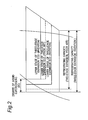
- the degree of liquid supercooling (SC) is increased by the upstream-side supercooling-use heat exchanger (upper stage of three-stage expansion ECO) and the downstream-side supercooling-use heat exchanger (lower stage of three-stage expansion ECO) so that the refrigerating capacity is improved, as compared with the refrigeration apparatus of the prior art (two-stage expansion) indicated by broken line.
- the refrigeration apparatus of the invention further includes a discharge-side supercooling control section 14 for detecting temperature and pressure of the refrigerant on the discharge side of the compressor 1 and, based on a result of the detection, performing control of the opening degree of the supercooling-use expansion part 12 in the downstream, and a suction-side supercooling control section 15 for detecting temperature and pressure of the refrigerant on the suction side of the compressor 1 in the upstream-side sub passage 11 and, based on a result of the detection, performing control of the opening degree of the supercooling-use expansion part 12 in the upstream.
- a discharge-side supercooling control section 14 for detecting temperature and pressure of the refrigerant on the discharge side of the compressor 1 and, based on a result of the detection, performing control of the opening degree of the supercooling-use expansion part 12 in the downstream
- a suction-side supercooling control section 15 for detecting temperature and pressure of the refrigerant on the suction side of the compressor 1 in the upstream-side sub passage
- the discharge-side supercooling control section 14 performs the opening degree control by calculating a present-time current SH value from a temperature and a high-pressure pressure value of the refrigerant within discharge piping of the compressor 1 and then comparing the obtained value with a previously set target SH value.
- the suction-side supercooling control section 15 performs the opening degree control by calculating a present-time current SH value from a temperature and a pressure value of the refrigerant within outlet piping of the upstream-side supercooling-use heat exchangers 13 and then comparing the obtained value with a previously set target SH value.
- the SH value refers to a degree of superheat, which is a temperature showing a difference from the temperature of a saturated state.
- the supercooling-use expansion part 12 is provided by using a temperature-sensitive expansion valve, thus allowing its price to be lowered as compared with the electronic expansion valve.
- an electronic expansion valve may also be used as the supercooling-use expansion part 12.
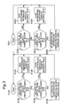
- control operation by the discharge-side supercooling control section 14 is described.
- the control operation starts (S101)
- control operation by the suction-side supercooling control section 15 is described.
- the control operation starts (S201)
- the downstream-side supercooling-use expansion part 12 is controlled by the discharge-side supercooling control section 14, while the upstream-side supercooling-use expansion part 12 is controlled by the suction-side supercooling control section 15. Therefore, the two supercooling-use expansion parts 12, 12 can be controlled based on different temperatures and pressures, respectively.
- the two supercooling-use expansion parts 12, 12 hunting of the opening and closing operations due to control exerted based on a common temperature and pressure can be avoided so that a stable cooling effect can be obtained.
- the two supercooling-use expansion parts 12, 12 are controlled by the discharge-side supercooling control section 14, the two supercooling-use expansion parts 12, 12 are controlled by a common pressure and temperature, so that the opening and closing operations may undergo occurrence of hunting, where a stable cooling effect could no be obtained.
- upstream-side supercooling-use expansion part 12 is controlled by the discharge-side supercooling control section 14 while the downstream-side supercooling-use expansion part 12 is controlled by the suction-side supercooling control section 15 additionally provided on the downstream-side sub passage 11.
- the sub passage 11, the supercooling-use expansion part 12 and the supercooling-use heat exchanger 13 may be provided each three or more in number, in which case one supercooling-use expansion part 12 is controlled by the discharge-side supercooling control section 14, and the other supercooling-use expansion parts 12 are controlled by the suction-side supercooling control sections 15 provided on the sub passages 11, respectively.
Landscapes
- Engineering & Computer Science (AREA)
- Physics & Mathematics (AREA)
- Mechanical Engineering (AREA)
- Thermal Sciences (AREA)
- General Engineering & Computer Science (AREA)
- Compression-Type Refrigeration Machines With Reversible Cycles (AREA)
- Applications Or Details Of Rotary Compressors (AREA)
- Air Conditioning Control Device (AREA)
- Devices That Are Associated With Refrigeration Equipment (AREA)
Abstract
A refrigeration apparatus includes two sub passages 11, 11 which are branched from a main passage 10 located between a condenser 2 and an expansion part 3 and which are connected to a compressor 1. On the sub passages 11 are provided supercooling-use expansion parts 12, and supercooling-use heat exchangers 13 for performing heat exchange between a refrigerant on an outlet side of the supercooling-use expansion part 12 and a refrigerant of the main passage 10. Therefore, each time the refrigerant of the main passage 10 passes through the two supercooling-use heat exchangers 13, 13, the degree of liquid supercooling of the refrigerant can be increased. Thus, there is provided a refrigeration apparatus capable of further increasing the degree of liquid supercooling of the refrigerant immediately before the expansion part 3 and thereby improving the refrigerating capacity and energy efficiency.
Description
- The present invention relates to a refrigeration apparatus in which, for example, a compressor, a condenser, an expansion part and an evaporator are connected to one another.
- In a conventional refrigeration apparatus, a compressor, a condenser, an expansion valve and an evaporator are connected to one another in a loop, where a supercooling-use heat exchanger is placed between the condenser and the expansion valve. Then, a liquid refrigerant derived from the condenser is branched into two flows. One flow of the liquid refrigerant makes a main flow liquid, while the other flow of the liquid refrigerant, after passing through the supercooling-use heat exchanger, super-cools the main flow liquid via the supercooling-use heat exchanger, then being led to the compression chamber of the compressor (see JP H11-248264 A, patent document 1).
- However, the prior art refrigeration apparatus is incapable of further increasing the degree of liquid supercooling of the refrigerant immediately before the expansion valve. Thus, there have been limitations in improving the refrigerating capacity and energy efficiency (COP).
Patent document 1: JP H11-248264 A, Fig. 1 - Accordingly, an object of the present invention is to provide a refrigeration apparatus which is capable of further increasing the degree of liquid supercooling of the refrigerant immediately before the expansion part, thus enabled to improve the refrigerating capacity and energy efficiency (COP).
- In order to achieve the objects, the refrigeration apparatus includes:
- a compressor;
- a condenser;
- an expansion part;.and
- an evaporator,
- wherein the compressor, the condenser, the expansion part and the evaporator are connected to one another in order,
- the refrigeration apparatus further includes:
- at least two sub passages which are branched from a main passage located between the condenser and the expansion part and which are connected to the compressor;
- supercooling-use expansion parts provided on the sub passages, respectively; and
- supercooling-use heat exchangers for performing heat exchange between a refrigerant on an outlet side of the supercooling-use expansion part and a refrigerant of the main passage.
- In this refrigeration apparatus of the invention, since the supercooling-use heat exchanger is provided at least two in number along the main passage, the degree of liquid supercooling (SC) can be increased each time the refrigerant of the main passage passes through the plurality of supercooling-use heat exchangers.
- That is, since the refrigeration apparatus of this invention has a so-called three- or more-stage expansion economizer cycle, the degree of liquid supercooling of the refrigerant immediately before the expansion part can be further increased so that the refrigerating capacity and energy efficiency (COP) can be further improved, as compared with prior-art refrigeration apparatuses having a two-stage expansion economizer cycle.
- Moreover, in the refrigeration apparatus of one embodiment, the compressor is a single screw compressor including a screw rotor and a pair of gate rotors which mesh with the screw rotor so as to sandwich the screw rotor from both sides, and the sub passages are provided two in number,
one of the sub passages being connected to one side of a boundary defined by the pair of gate rotors, and the other of the sub passages being connected to the other side of the boundary defined by the pair of gate rotors. - In the refrigeration apparatus of this one embodiment, since the sub passage and the supercooling-use heat exchanger are provided two in number, an economizer cycle can be applied to each of compression spaces divided by an boundary defined by the pair of gate rotors in the compressor. Thus, a so-called three-stage expansion economizer cycle becomes applicable, so that performance improvement can be achieved.
- Moreover, in the refrigeration apparatus of one embodiment, the refrigeration apparatus includes:
- a discharge-side supercooling control section for detecting temperature and pressure of the refrigerant on the discharge side of the compressor and, based on a result of the detection, performing control of an opening degree of the supercooling-use expansion part in one of the sub passages; and
- a suction-side supercooling control section for detecting temperature and pressure of the refrigerant on the suction side of the compressor in the other sub passage and, based on a result of the detection, performing control of an opening degree of the supercooling-use expansion part in the other sub passage.
- In the refrigeration apparatus of this one embodiment, since one of the supercooling-use expansion parts is controlled by the discharge-side supercooling control section while the other supercooling-use expansion part is controlled by the suction-side supercooling control section, the two supercooling-use expansion parts can be controlled based on different temperatures and pressures, respectively.
- Consequently, in the two supercooling-use expansion parts, hunting of the opening and closing operations due to control exerted based on a common temperature and pressure can be avoided so that a stable cooling effect can be obtained.
- According to the refrigeration apparatus of the present invention, since the supercooling-use heat exchanger is provided at least two in number along the main passage, the degree of liquid supercooling of the refrigerant immediately before the expansion part can be increased so that the refrigerating capacity and energy efficiency can be improved.
- Also, according to the refrigeration apparatus of one embodiment, since the economizer cycle is applied to each of the divisional compression spaces of the compressor, performance improvement can be achieved.
- Also, according to the refrigeration apparatus of one embodiment, since the two supercooling-use expansion parts are controlled based on different temperatures and pressures, respectively, competition of the opening and closing operations between the two supercooling-use expansion parts can be prevented so that a stable cooling effect can be obtained.
-
- Fig. 1 is a simplified configurational view showing an embodiment of the refrigeration apparatus of the present invention;
- Fig. 2 is a PH diagram for comparison between the refrigeration apparatus of the invention and a refrigeration apparatus of a prior art; and
- Fig. 3 is a flowchart showing the control of a discharge-side supercooling control section and a suction-side supercooling control section.
-
- 1
- a compressor
- 1a
- a screw rotor
- 1b
- a gate rotor
- 2
- a condenser
- 3
- an expansion part
- 4
- an evaporator
- 10
- a main passage
- 11
- a sub passage
- 12
- a supercooling-use expansion part
- 13
- a supercooling-use heat exchanger
- 14
- a discharge-side supercooling control section
- 15
- a suction-side supercooling control section
- Hereinbelow, the present invention will be described in detail by embodiments thereof illustrated in the accompanying drawings.
- Fig. 1 shows a simplified configurational view showing an embodiment of the refrigeration apparatus of the invention. In this refrigeration apparatus, a compressor 1, a condenser 2, an
expansion part 3 and anevaporator 4 are connected to one another in a loop, constituting a refrigeration cycle using a refrigerant. - This refrigeration cycle is explained. A vapor phase refrigerant discharged by the compressor 1 has its heat absorbed in the condenser 2, resulting in a liquid phase state. The resulting liquid phase refrigerant is decompressed by the
expansion part 3, resulting in a two-phase state of vapor phase and liquid phase. Thereafter, the two-phase refrigerant (wet gas) has heat imparted in theevaporator 4, resulting in a vapor phase state. The resulting vapor phase refrigerant is sucked and pressurized in the compressor 1, and then discharged in the compressor 1 again. - As the compressor 1, for example, a single screw compressor is used. In more detail, the compressor 1 includes a
screw rotor 1a, and a pair ofgate rotors screw rotor 1a so as to sandwich the same from both sides. Meshing between a thread groove of thescrew rotor 1a and tooth portions of the one pair ofgate rotors - The condenser 2 includes a fan 7, and the refrigerant is cooled by air cooling of the fan 7. The
expansion part 3 is given by using, for example, an electronically controlled expansion valve or a capillary tube. Theevaporator 4 is given by using, for example, a heat exchanger for cooling water (liquid heat transfer medium) by the refrigerant. - Moreover, this refrigeration apparatus has two
sub passages main passage 10 between the condenser 2 and theexpansion part 3 and connected to the compressor 1. It is noted that themain passage 10 and thesub passages 11 are implemented by piping. - More specifically, by the branch from upstream and downstream sides of the
main passage 10, an upstream-side sub passage 11 and a downstream-side sub passage 11 are formed. This upstream-side sub passage 11 is connected to one side of the pair ofgate rotors side sub passage 11 is connected to the other side of the pair ofgate rotors side sub passage 11 communicates with a midway portion of the compression chamber located on one side of the boundary given by the pair ofgate rotors side sub passage 11 communicates with a midway portion of the compression chamber located on the other side of the boundary given by the pair ofgate rotors - Further, a supercooling-
use expansion part 12 and a supercooling-use heat exchanger 13 for performing heat exchange between the refrigerant on the outlet side of the supercooling-use expansion part 12 and the refrigerant of themain passage 10 are provided on each of thesesub passages 11. - More specifically, an upstream-side supercooling-use heat exchanger (higher-stage economizer) 13 and a downstream-side supercooling-use heat exchanger (lower-stage economizer) 13 are set along the
main passage 10. In Fig. 1, although thesub passages 11 are branched from themain passage 10 on the downstream side of the supercooling-use heat exchanger 13, yet thosesub passages 11 may also be branched from themain passage 10 on the upstream side of the supercooling-use heat exchanger 13. - Next, operation of the two supercooling-
use heat exchangers main passage 10, coming from the condenser 2, is first diverged to the upstream-side sub passage 11. This liquid phase refrigerant in the upstream-side sub passage 11 is decompressed by the supercooling-use expansion part 12, resulting in a two-phase refrigerant of vapor phase and liquid phase. The resulting two-phase refrigerant absorbs heat from the liquid phase refrigerant of themain passage 10 via the upstream-side supercooling-use heat exchanger 13, resulting in a vapor phase refrigerant. The resulting vapor phase refrigerant is sucked into the compressor 1. In this process, the liquid phase refrigerant in themain passage 10 is cooled via the upstream-side supercooling-use heat exchanger 13. - Thereafter, the cooled liquid phase refrigerant in the
main passage 10 is diverged to the downstream-side sub passage 11. The liquid phase refrigerant in the downstream-side sub passage 11 is decompressed in the supercooling-use expansion part 12, resulting in a two-phase refrigerant of vapor phase and liquid phase. The resulting two-phase refrigerant absorbs heat from the liquid phase refrigerant of themain passage 10 via the downstream-side supercooling-use heat exchanger 13, resulting in a vapor phase refrigerant. The resulting vapor phase refrigerant is sucked into the compressor 1. In this process, the liquid phase refrigerant in themain passage 10 is cooled via the downstream-side supercooling-use heat exchanger 13. - According to the refrigeration apparatus having the above-described construction, since the two supercooling-
use heat exchangers main passage 10 can be increased in the degree of liquid supercooling each time it passes through the two supercooling-use heat exchangers - That is, the refrigeration apparatus of this invention, by virtue of its having a three-stage expansion economizer cycle made up of the three
expansion parts use heat exchangers expansion part 3, thus capable of further improving the refrigerating capacity and energy efficiency (COP), as compared with the prior-art refrigeration apparatus having a two-stage expansion economizer cycle made up of two expansion valves and one supercooling-use heat exchanger. - More specifically, as shown in Fig. 2, in the refrigeration apparatus of the invention (three-stage expansion) indicated by solid line, the degree of liquid supercooling (SC) is increased by the upstream-side supercooling-use heat exchanger (upper stage of three-stage expansion ECO) and the downstream-side supercooling-use heat exchanger (lower stage of three-stage expansion ECO) so that the refrigerating capacity is improved, as compared with the refrigeration apparatus of the prior art (two-stage expansion) indicated by broken line.
- Moreover, the refrigeration apparatus of the invention, as shown in Fig. 1, further includes a discharge-side
supercooling control section 14 for detecting temperature and pressure of the refrigerant on the discharge side of the compressor 1 and, based on a result of the detection, performing control of the opening degree of the supercooling-use expansion part 12 in the downstream, and a suction-sidesupercooling control section 15 for detecting temperature and pressure of the refrigerant on the suction side of the compressor 1 in the upstream-side sub passage 11 and, based on a result of the detection, performing control of the opening degree of the supercooling-use expansion part 12 in the upstream. - More specifically, the discharge-side
supercooling control section 14 performs the opening degree control by calculating a present-time current SH value from a temperature and a high-pressure pressure value of the refrigerant within discharge piping of the compressor 1 and then comparing the obtained value with a previously set target SH value. The suction-sidesupercooling control section 15 performs the opening degree control by calculating a present-time current SH value from a temperature and a pressure value of the refrigerant within outlet piping of the upstream-side supercooling-use heat exchangers 13 and then comparing the obtained value with a previously set target SH value. It is noted here that the SH value refers to a degree of superheat, which is a temperature showing a difference from the temperature of a saturated state. - The supercooling-
use expansion part 12 is provided by using a temperature-sensitive expansion valve, thus allowing its price to be lowered as compared with the electronic expansion valve. Of course, an electronic expansion valve may also be used as the supercooling-use expansion part 12. - Next, referring to Fig. 3, operations of the discharge-side
supercooling control section 14 and the suction-sidesupercooling control section 15 are explained. - First, control operation by the discharge-side
supercooling control section 14 is described. As the control operation starts (S101), it is decided whether or not the current SH value (B) is greater than the target SH value (A) (S102). If it is greater, thecontrol section 14 opens the downstream-side temperature-sensitive expansion valve 12 (S103). Conversely, if it is not greater, it is decided whether or not the current SH value (B) is smaller than the target SH value (A) (S104). Then, if it is smaller, thecontrol section 14 closes the downstream-side temperature-sensitive expansion valve 12 (S105). Conversely, if it is not smaller, thecontrol section 14 does not perform any operation for the downstream-side temperature-sensitive expansion valve 12 (S106). - Next, control operation by the suction-side
supercooling control section 15 is described. As the control operation starts (S201), it is decided whether or not the current SH value (D) is greater than the target SH value (C) (S202). If it is greater, thecontrol section 15 opens the upstream-side temperature-sensitive expansion valve 12 (S203). Conversely, if it is not greater, it is decided whether or not the current SH value (D) is smaller than the target SH value (C) (S204). Then, if it is smaller, thecontrol section 15 closes the upstream-side temperature-sensitive expansion valve 12 (S205). Conversely, if it is not smaller, thecontrol section 15 does not perform any operation for the upstream-side temperature-sensitive expansion valve 12 (S206). - As shown above, the downstream-side supercooling-
use expansion part 12 is controlled by the discharge-sidesupercooling control section 14, while the upstream-side supercooling-use expansion part 12 is controlled by the suction-sidesupercooling control section 15. Therefore, the two supercooling-use expansion parts - Thus, in the two supercooling-
use expansion parts use expansion parts supercooling control section 14, the two supercooling-use expansion parts - Without being limited to the above-described embodiment, the present invention may be subject to design changes within the scope of the invention unless they depart therefrom. It is also possible, for example, that upstream-side supercooling-
use expansion part 12 is controlled by the discharge-sidesupercooling control section 14 while the downstream-side supercooling-use expansion part 12 is controlled by the suction-sidesupercooling control section 15 additionally provided on the downstream-side sub passage 11. Also, thesub passage 11, the supercooling-use expansion part 12 and the supercooling-use heat exchanger 13 may be provided each three or more in number, in which case one supercooling-use expansion part 12 is controlled by the discharge-sidesupercooling control section 14, and the other supercooling-use expansion parts 12 are controlled by the suction-sidesupercooling control sections 15 provided on thesub passages 11, respectively.
Claims (3)
- A refrigeration apparatus comprising:a compressor (1);a condenser (2);an expansion part (3); andan evaporator (4),wherein the compressor (1), the condenser (2), the expansion part (3) and the evaporator (4) are connected to one another in order,the refrigeration apparatus further comprising:at least two sub passages (11) which are branched from a main passage (10) located between the condenser (2) and the expansion part (3) and which are connected to the compressor (1);supercooling-use expansion parts (12) provided on the sub passages (11), respectively; andsupercooling-use heat exchangers (13) for performing heat exchange between a refrigerant on an outlet side of the supercooling-use expansion part (12) and a refrigerant of the main passage (10).
- The refrigeration apparatus as claimed in Claim 1, wherein
the compressor (1) is a single screw compressor including a screw rotor (1a) and a pair of gate rotors (1b, 1b) which mesh with the screw rotor (1a) so as to sandwich the screw rotor (1a) from both sides, and the sub passages (11) are provided two in number,
one of the sub passages (11) being connected to one side of a boundary defined by the pair of gate rotors (1b, 1b), and the other of the sub passages (11) being connected to the other side of the boundary defined by the pair of gate rotors (1b, 1b). - The refrigeration apparatus as claimed in Claim 2, further comprising:a discharge-side supercooling control section (14) for detecting temperature and pressure of the refrigerant on the discharge side of the compressor (1) and, based on a result of the detection, performing control of an opening degree of the supercooling-use expansion part (12) in one of the sub passages (11); anda suction-side supercooling control section (15) for detecting temperature and pressure of the refrigerant on the suction side of the compressor (1) in the other sub passage (11) and, based on a result of the detection, performing control of an opening degree of the supercooling-use expansion part (12) in the other sub passage (11).
Applications Claiming Priority (2)
| Application Number | Priority Date | Filing Date | Title |
|---|---|---|---|
| JP2003313439A JP4433729B2 (en) | 2003-09-05 | 2003-09-05 | Refrigeration equipment |
| PCT/JP2004/011770 WO2005024313A1 (en) | 2003-09-05 | 2004-08-17 | Freezer device |
Publications (2)
| Publication Number | Publication Date |
|---|---|
| EP1669694A1 true EP1669694A1 (en) | 2006-06-14 |
| EP1669694A4 EP1669694A4 (en) | 2009-04-08 |
Family
ID=34269770
Family Applications (1)
| Application Number | Title | Priority Date | Filing Date |
|---|---|---|---|
| EP04771731A Withdrawn EP1669694A4 (en) | 2003-09-05 | 2004-08-17 | FREEZER |
Country Status (6)
| Country | Link |
|---|---|
| US (1) | US7640762B2 (en) |
| EP (1) | EP1669694A4 (en) |
| JP (1) | JP4433729B2 (en) |
| CN (1) | CN100476316C (en) |
| TW (1) | TWI285249B (en) |
| WO (1) | WO2005024313A1 (en) |
Cited By (4)
| Publication number | Priority date | Publication date | Assignee | Title |
|---|---|---|---|---|
| EP2097703A4 (en) * | 2006-12-29 | 2012-08-29 | Carrier Corp | Economizer heat exchanger |
| EP2631563A1 (en) * | 2012-02-23 | 2013-08-28 | LG Electronics, Inc. | Air conditioner and control method thereof |
| EP2455688A3 (en) * | 2010-11-23 | 2014-03-05 | LG Electronics Inc. | Heat pump and method of controlling the same |
| EP2527764A3 (en) * | 2008-03-31 | 2014-06-18 | Mitsubishi Electric Corporation | Heat pump type hot water supply outdoor apparatus |
Families Citing this family (18)
| Publication number | Priority date | Publication date | Assignee | Title |
|---|---|---|---|---|
| US9163865B2 (en) | 2008-06-13 | 2015-10-20 | Mitsubishi Electric Corporation | Refrigeration cycle device and method of controlling the same |
| JP2008039332A (en) * | 2006-08-09 | 2008-02-21 | Mitsubishi Heavy Ind Ltd | Multiple heat pump air conditioner |
| KR101333984B1 (en) | 2006-10-17 | 2013-11-27 | 엘지전자 주식회사 | Air conditioner |
| DE102007013485B4 (en) * | 2007-03-21 | 2020-02-20 | Gea Refrigeration Germany Gmbh | Process for controlling a CO2 refrigeration system with two-stage compression |
| JP4969287B2 (en) * | 2007-03-28 | 2012-07-04 | 三菱電機株式会社 | Refrigeration cycle equipment |
| JP4989507B2 (en) * | 2008-02-15 | 2012-08-01 | 三菱電機株式会社 | Refrigeration equipment |
| CN103119382B (en) * | 2010-09-14 | 2015-07-01 | 江森自控科技公司 | System and method for controlling an economizer circuit |
| KR101382084B1 (en) * | 2011-09-07 | 2014-04-04 | 엘지전자 주식회사 | An air conditioner |
| JP5792585B2 (en) * | 2011-10-18 | 2015-10-14 | サンデンホールディングス株式会社 | Refrigerator, refrigerated showcase and vending machine |
| US9733005B2 (en) | 2013-03-15 | 2017-08-15 | Johnson Controls Technology Company | Subcooling system with thermal storage |
| KR102103360B1 (en) * | 2013-04-15 | 2020-05-29 | 엘지전자 주식회사 | Air Conditioner and Controlling method for the same |
| CN103307817B (en) * | 2013-06-17 | 2015-08-05 | 江苏科立德制冷设备有限公司 | A kind of vortex parallel Condensing units |
| CN103344067B (en) * | 2013-06-17 | 2015-09-09 | 江苏科立德制冷设备有限公司 | A kind of low-temperature vortex parallel-connection Condensing units |
| US10595536B2 (en) * | 2014-02-10 | 2020-03-24 | Ibex Bionomics Llc | Bio-derived compositions |
| US10595535B2 (en) * | 2014-02-10 | 2020-03-24 | Ibex Bionomics Llc | Bio-derived compositions for use in agriculture |
| US10047985B2 (en) | 2014-03-10 | 2018-08-14 | Johnson Controls Technology Company | Subcooling system with thermal energy storage |
| WO2017203642A1 (en) * | 2016-05-25 | 2017-11-30 | 三菱電機株式会社 | Screw compressor and refrigeration cycle device |
| WO2019084870A1 (en) * | 2017-11-02 | 2019-05-09 | 太仓富华特种电机有限公司 | Industrial cooling unit with adjustable cooling power |
Family Cites Families (21)
| Publication number | Priority date | Publication date | Assignee | Title |
|---|---|---|---|---|
| US2024323A (en) * | 1932-07-01 | 1935-12-17 | Baldwin Southwark Corp | Apparatus for compressing gaseous fluids |
| US2463881A (en) * | 1946-07-06 | 1949-03-08 | Muncie Gear Works Inc | Heat pump |
| US2677944A (en) * | 1950-12-01 | 1954-05-11 | Alonzo W Ruff | Plural stage refrigeration apparatus |
| US2897659A (en) * | 1954-08-09 | 1959-08-04 | Ckd Stalingrad Narodni Podnik | Apparatus for gas and liquid cooling in compressor plants with two- or multistage cooling circuit |
| GB1555330A (en) * | 1978-03-21 | 1979-11-07 | Hall Thermotank Prod Ltd | Rotary fluid machines |
| US4602485A (en) * | 1983-04-23 | 1986-07-29 | Daikin Industries, Ltd. | Refrigeration unit including a hot gas defrosting system |
| JPH0784955B2 (en) | 1989-04-26 | 1995-09-13 | ダイキン工業株式会社 | Screw refrigerator |
| JPH0460348A (en) | 1990-06-27 | 1992-02-26 | Daikin Ind Ltd | Screw type freezer |
| JPH05322334A (en) | 1992-05-20 | 1993-12-07 | Hitachi Ltd | Multistage compression refrigeration cycle and method of starting the same |
| JP3443443B2 (en) | 1993-12-24 | 2003-09-02 | 株式会社神戸製鋼所 | Screw refrigerator |
| JPH09210480A (en) | 1996-01-31 | 1997-08-12 | Mitsubishi Heavy Ind Ltd | Two-stage compression refrigeration system |
| US6058727A (en) * | 1997-12-19 | 2000-05-09 | Carrier Corporation | Refrigeration system with integrated oil cooling heat exchanger |
| JPH11248264A (en) | 1998-03-04 | 1999-09-14 | Hitachi Ltd | Refrigeration equipment |
| JP2000220893A (en) | 1999-02-01 | 2000-08-08 | Ebara Corp | Semi-hermetic screw refrigerator |
| JP2001099498A (en) | 1999-09-30 | 2001-04-13 | Dairei:Kk | Refrigeration system using non-azeotropic mixed refrigerant |
| US6718781B2 (en) * | 2001-07-11 | 2004-04-13 | Thermo King Corporation | Refrigeration unit apparatus and method |
| US6694750B1 (en) * | 2002-08-21 | 2004-02-24 | Carrier Corporation | Refrigeration system employing multiple economizer circuits |
| CA2567880A1 (en) * | 2004-05-28 | 2005-12-15 | York International Corporation | System and method for controlling an economizer circuit |
| US20060064257A1 (en) * | 2004-09-21 | 2006-03-23 | Graham Packaging Company, L.P. | Test device for measuring a container response |
| CN101501415B (en) * | 2006-08-01 | 2012-09-05 | 开利公司 | Refrigeration system and operation method |
| KR20090041846A (en) * | 2007-10-25 | 2009-04-29 | 엘지전자 주식회사 | Air conditioner |
-
2003
- 2003-09-05 JP JP2003313439A patent/JP4433729B2/en not_active Expired - Fee Related
-
2004
- 2004-08-17 EP EP04771731A patent/EP1669694A4/en not_active Withdrawn
- 2004-08-17 CN CNB2004800255274A patent/CN100476316C/en not_active Expired - Fee Related
- 2004-08-17 US US10/570,326 patent/US7640762B2/en not_active Expired - Fee Related
- 2004-08-17 WO PCT/JP2004/011770 patent/WO2005024313A1/en not_active Ceased
- 2004-09-03 TW TW093126730A patent/TWI285249B/en not_active IP Right Cessation
Cited By (6)
| Publication number | Priority date | Publication date | Assignee | Title |
|---|---|---|---|---|
| EP2097703A4 (en) * | 2006-12-29 | 2012-08-29 | Carrier Corp | Economizer heat exchanger |
| US8312737B2 (en) | 2006-12-29 | 2012-11-20 | Carrier Corporation | Economizer heat exchanger |
| EP2527764A3 (en) * | 2008-03-31 | 2014-06-18 | Mitsubishi Electric Corporation | Heat pump type hot water supply outdoor apparatus |
| EP2455688A3 (en) * | 2010-11-23 | 2014-03-05 | LG Electronics Inc. | Heat pump and method of controlling the same |
| EP2631563A1 (en) * | 2012-02-23 | 2013-08-28 | LG Electronics, Inc. | Air conditioner and control method thereof |
| US9347697B2 (en) | 2012-02-23 | 2016-05-24 | Lg Electronics Inc. | Air conditioner and control method thereof |
Also Published As
| Publication number | Publication date |
|---|---|
| JP4433729B2 (en) | 2010-03-17 |
| JP2005083609A (en) | 2005-03-31 |
| US7640762B2 (en) | 2010-01-05 |
| WO2005024313A1 (en) | 2005-03-17 |
| TWI285249B (en) | 2007-08-11 |
| EP1669694A4 (en) | 2009-04-08 |
| US20070017249A1 (en) | 2007-01-25 |
| TW200513620A (en) | 2005-04-16 |
| CN1846099A (en) | 2006-10-11 |
| CN100476316C (en) | 2009-04-08 |
Similar Documents
| Publication | Publication Date | Title |
|---|---|---|
| US7640762B2 (en) | Refrigeration apparatus | |
| US6474087B1 (en) | Method and apparatus for the control of economizer circuit flow for optimum performance | |
| KR100484802B1 (en) | Frost removing method of air conditioner hanving two compressor | |
| US6779356B2 (en) | Apparatus and method for controlling operation of air conditioner | |
| KR100382488B1 (en) | Method for controlling Linear Expantion Valve of air conditioner with 2 compressors | |
| US7257958B2 (en) | Multi-temperature cooling system | |
| US20080302129A1 (en) | Refrigeration system for transcritical operation with economizer and low-pressure receiver | |
| EP2587177A2 (en) | Air conditioner | |
| EP3217121A1 (en) | Outdoor unit for air conditioner and method for controlling air conditioner | |
| JP6715929B2 (en) | Refrigeration cycle device and air conditioner including the same | |
| EP3617617B1 (en) | Outdoor unit and method for controlling same | |
| EP1956320A1 (en) | Freezing device | |
| JP5235925B2 (en) | Refrigeration equipment | |
| US12313341B2 (en) | Heat transfer tube and heat exchanger | |
| JP2011214753A (en) | Refrigerating device | |
| EP1666729A1 (en) | Screw compressor and freezer | |
| CN104676935A (en) | Refrigerating circulation device | |
| CN101144656A (en) | air conditioner | |
| US20050252236A1 (en) | Refrigeration equipment | |
| JP4352327B2 (en) | Ejector cycle | |
| JPWO2020148826A1 (en) | Air conditioner | |
| JP6381712B2 (en) | Refrigeration cycle equipment | |
| JP2006242515A (en) | Refrigeration equipment | |
| US20240230167A9 (en) | Refrigeration cycle apparatus | |
| KR20110059344A (en) | Chiller and how to drive it |
Legal Events
| Date | Code | Title | Description |
|---|---|---|---|
| PUAI | Public reference made under article 153(3) epc to a published international application that has entered the european phase |
Free format text: ORIGINAL CODE: 0009012 |
|
| 17P | Request for examination filed |
Effective date: 20060222 |
|
| AK | Designated contracting states |
Kind code of ref document: A1 Designated state(s): AT BE BG CH CY CZ DE DK EE ES FI FR GB GR HU IE IT LI LU MC NL PL PT RO SE SI SK TR |
|
| DAX | Request for extension of the european patent (deleted) | ||
| A4 | Supplementary search report drawn up and despatched |
Effective date: 20090311 |
|
| 17Q | First examination report despatched |
Effective date: 20160219 |
|
| STAA | Information on the status of an ep patent application or granted ep patent |
Free format text: STATUS: THE APPLICATION IS DEEMED TO BE WITHDRAWN |
|
| 18D | Application deemed to be withdrawn |
Effective date: 20160630 |