EP1669487A1 - Washing machine combined with dryer - Google Patents
Washing machine combined with dryer Download PDFInfo
- Publication number
- EP1669487A1 EP1669487A1 EP05291433A EP05291433A EP1669487A1 EP 1669487 A1 EP1669487 A1 EP 1669487A1 EP 05291433 A EP05291433 A EP 05291433A EP 05291433 A EP05291433 A EP 05291433A EP 1669487 A1 EP1669487 A1 EP 1669487A1
- Authority
- EP
- European Patent Office
- Prior art keywords
- filter
- washing machine
- air
- machine according
- tub
- Prior art date
- Legal status (The legal status is an assumption and is not a legal conclusion. Google has not performed a legal analysis and makes no representation as to the accuracy of the status listed.)
- Granted
Links
- 238000005406 washing Methods 0.000 title claims abstract description 75
- XLYOFNOQVPJJNP-UHFFFAOYSA-N water Substances O XLYOFNOQVPJJNP-UHFFFAOYSA-N 0.000 claims description 73
- 230000008878 coupling Effects 0.000 claims description 22
- 238000010168 coupling process Methods 0.000 claims description 22
- 238000005859 coupling reaction Methods 0.000 claims description 22
- 239000008400 supply water Substances 0.000 claims description 6
- 238000003780 insertion Methods 0.000 claims description 3
- 230000037431 insertion Effects 0.000 claims description 3
- 239000003779 heat-resistant material Substances 0.000 claims description 2
- 239000003599 detergent Substances 0.000 description 16
- 238000010981 drying operation Methods 0.000 description 15
- 238000004140 cleaning Methods 0.000 description 4
- 230000000903 blocking effect Effects 0.000 description 2
- 238000001035 drying Methods 0.000 description 2
- 239000002979 fabric softener Substances 0.000 description 2
- 239000013505 freshwater Substances 0.000 description 2
- 238000002347 injection Methods 0.000 description 2
- 239000007924 injection Substances 0.000 description 2
- 238000012986 modification Methods 0.000 description 2
- 230000004048 modification Effects 0.000 description 2
- 238000010276 construction Methods 0.000 description 1
- 238000011109 contamination Methods 0.000 description 1
- 239000000498 cooling water Substances 0.000 description 1
- 238000007599 discharging Methods 0.000 description 1
- 239000000428 dust Substances 0.000 description 1
- 230000033001 locomotion Effects 0.000 description 1
- 239000000463 material Substances 0.000 description 1
- 238000000034 method Methods 0.000 description 1
- 239000000203 mixture Substances 0.000 description 1
- 239000002245 particle Substances 0.000 description 1
- 238000003825 pressing Methods 0.000 description 1
- 230000008439 repair process Effects 0.000 description 1
- 239000008237 rinsing water Substances 0.000 description 1
- 238000007789 sealing Methods 0.000 description 1
- 239000000126 substance Substances 0.000 description 1
Images

Classifications
-
- D—TEXTILES; PAPER
- D06—TREATMENT OF TEXTILES OR THE LIKE; LAUNDERING; FLEXIBLE MATERIALS NOT OTHERWISE PROVIDED FOR
- D06F—LAUNDERING, DRYING, IRONING, PRESSING OR FOLDING TEXTILE ARTICLES
- D06F39/00—Details of washing machines not specific to a single type of machines covered by groups D06F9/00 - D06F27/00
- D06F39/10—Filtering arrangements
-
- D—TEXTILES; PAPER
- D06—TREATMENT OF TEXTILES OR THE LIKE; LAUNDERING; FLEXIBLE MATERIALS NOT OTHERWISE PROVIDED FOR
- D06F—LAUNDERING, DRYING, IRONING, PRESSING OR FOLDING TEXTILE ARTICLES
- D06F25/00—Washing machines with receptacles, e.g. perforated, having a rotary movement, e.g. oscillatory movement, the receptacle serving both for washing and for centrifugally separating water from the laundry and having further drying means, e.g. using hot air
-
- D—TEXTILES; PAPER
- D06—TREATMENT OF TEXTILES OR THE LIKE; LAUNDERING; FLEXIBLE MATERIALS NOT OTHERWISE PROVIDED FOR
- D06F—LAUNDERING, DRYING, IRONING, PRESSING OR FOLDING TEXTILE ARTICLES
- D06F33/00—Control of operations performed in washing machines or washer-dryers
- D06F33/50—Control of washer-dryers characterised by the purpose or target of the control
- D06F33/69—Control of cleaning or disinfection of washer-dryer parts, e.g. of tubs
-
- D—TEXTILES; PAPER
- D06—TREATMENT OF TEXTILES OR THE LIKE; LAUNDERING; FLEXIBLE MATERIALS NOT OTHERWISE PROVIDED FOR
- D06F—LAUNDERING, DRYING, IRONING, PRESSING OR FOLDING TEXTILE ARTICLES
- D06F37/00—Details specific to washing machines covered by groups D06F21/00 - D06F25/00
- D06F37/26—Casings; Tubs
- D06F37/267—Tubs specially adapted for mounting thereto components or devices not provided for in preceding subgroups
-
- D—TEXTILES; PAPER
- D06—TREATMENT OF TEXTILES OR THE LIKE; LAUNDERING; FLEXIBLE MATERIALS NOT OTHERWISE PROVIDED FOR
- D06F—LAUNDERING, DRYING, IRONING, PRESSING OR FOLDING TEXTILE ARTICLES
- D06F39/00—Details of washing machines not specific to a single type of machines covered by groups D06F9/00 - D06F27/00
- D06F39/02—Devices for adding soap or other washing agents
-
- D—TEXTILES; PAPER
- D06—TREATMENT OF TEXTILES OR THE LIKE; LAUNDERING; FLEXIBLE MATERIALS NOT OTHERWISE PROVIDED FOR
- D06F—LAUNDERING, DRYING, IRONING, PRESSING OR FOLDING TEXTILE ARTICLES
- D06F39/00—Details of washing machines not specific to a single type of machines covered by groups D06F9/00 - D06F27/00
- D06F39/12—Casings; Tubs
-
- D—TEXTILES; PAPER
- D06—TREATMENT OF TEXTILES OR THE LIKE; LAUNDERING; FLEXIBLE MATERIALS NOT OTHERWISE PROVIDED FOR
- D06F—LAUNDERING, DRYING, IRONING, PRESSING OR FOLDING TEXTILE ARTICLES
- D06F58/00—Domestic laundry dryers
- D06F58/20—General details of domestic laundry dryers
- D06F58/22—Lint collecting arrangements
-
- D—TEXTILES; PAPER
- D06—TREATMENT OF TEXTILES OR THE LIKE; LAUNDERING; FLEXIBLE MATERIALS NOT OTHERWISE PROVIDED FOR
- D06F—LAUNDERING, DRYING, IRONING, PRESSING OR FOLDING TEXTILE ARTICLES
- D06F37/00—Details specific to washing machines covered by groups D06F21/00 - D06F25/00
- D06F37/42—Safety arrangements, e.g. for stopping rotation of the receptacle upon opening of the casing door
Definitions
- the present invention relates to a washing machine, and more particularly, to a drum type washing machine combined with a dryer, in which a lint filter assembly is provided to collect and remove foreign substances such as lint generated during a heat drying operation.
- a washing machine is a home appliance for washing clothes automatically.
- a typical washing machine uses an electric motor as a driving unit to agitate clothes together with water containing detergent to remove dirt from the clothes.
- the washing process of the washing machine generally includes washing, rinsing, spin-drying, and/or heat-drying operations.
- Washing machines can be classified into a drum type washing machine, an agitator type washing machine, and a pulsator type washing machine.
- the drum type washing machine includes a plurality of lifters inside of a drum to lift up and drop down clothes in the drum as the drum is rotated about a horizontal axis at a low speed. Therefore, the clothes can be cleaned by the collision with water containing detergent.
- washing machine combined with a dryer is recently introduced to satisfy user's demand.
- clothes are heat dried after washed, rinsed, and spin dried.
- the washing machine combined with the dryer can be classified into a condenser type and a vented type depending on a drying method.
- the washing machine combined with the condenser type dryer removes residual moisture from clothes by circulating air through a drum, a heat exchanger, and a heater without discharging the air out of the washing machine until the heat drying operation is completed. That is, the air becomes moist after passing through the drum, the moist air cools down at the heat exchanger by exchanging heat with a cooling water, the moisture in the air condenses and drops down to the bottom of the tub as the moist air cools down, and the air is heated again by the heater and then enters the drum again.
- the moist air which is discharged from the washing machine combined with the vented type dryer, contains lint such as fluff, thereby contaminating the indoor air.
- the lint in the moist air falls down and builds up while it is discharged from the tub to the outside through the vent duct.
- the lint builds up on a pleated surface of the connecting pipe connected between the tub and the vent duct.
- the build-up of the lint becomes bigger according to the time of use, blocking the vent duct.
- the build-up of the lint increases the possibility of fire. Therefore, there is an increasing need for a structure that can remove the problems related to the lint.
- the present invention is directed to a washing machine combined with a dryer that substantially obviates one or more problems due to limitations and disadvantages of the related art.
- An object of the present invention is to provide a washing machine combined with a vented type dryer, in which an air-vent line, including an air-vent hose connected between a tub and the air-vent duct, is prevented from being plugged by lint generated during a heat drying operation.
- Another object of the present invention is to provide a washing machine combined with a dryer, in which lint generated during a heat drying operation is prevented from building up in an air-vent line and therefore the possibility of fire reduces.
- a further another object of the present invention is to provide a washing machine combined with a dryer that has a lint filter assembly to remove lint, the lint filter assembly being designed such that a user can easily install and replace it.
- a washing machine combined with a dryer including: a cabinet; a tub installed in the cabinet; an air-vent hose installed to an outer surface of the tub; a lint filter assembly having one end connected to the air-vent hose to remove lint from air discharged from the tub; and an air-vent duct connected to the other end of the lint filter assembly.
- a washing machine combined with a dryer, including: a tub provided with an air-vent hose at an outer surface; a water inlet hose to supply water to the tub; a filter housing including an air inlet connected to the air-vent hose, an air outlet to discharge air introduced from the air inlet, and a nozzle to inject water into the filter housing; a filter cover to cover a top of the filter housing; and a filter unit inserted into the filter housing through the filter cover.
- a washing machine combined with a dryer, including: a tub; a water inlet hose to supply water to the tub; and a lint filter assembly including a filter housing having a chamber for passing a moist air discharged from the tub therethrough, a filter cover to cover a top of the filter housing, and a filter unit inserted into the filter housing through the filter cover.
- the lint generated during the heat drying operation is separated and collected from the moist air before the moist air is discharged to the outside, thereby preventing the indoor air from contamination.
- the water from the water inlet hose is injected toward filter at a high pressure to remove the lint from the filter and direct the removed lint to the bottom of the tub, thereby reducing manual filter cleaning.
- the filter unit is removably installed such that a use can easily clean the filter, thereby preventing the lint from blocking the filter and the air vent passage.
- the filter is removably installed to allow manual cleaning in addition to the automatic cleaning by the water injection, thereby reducing the possibility of fire due to the combination of hot air from the tub and the build-up of lint on the filter.
- Fig. 1 is a sectional view of a washing machine combined with a dryer, in which a lint filter assembly is provided according to the present invention
- Fig. 2 is a perspective view of a lint filter assembly according to the present invention.
- Fig. 3 is an exploded perspective view of the lint filter assembly depicted in Fig. 2;
- Fig. 4 is an enlarged cut-away view of the portion encircled by line "A" in Fig. 1;
- Fig. 5 is an enlarged view sectional view of the portion encircled by line "B" in Fig. 3.
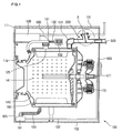
- Fig. 1 is a sectional view of a washing machine combined with a dryer, in which a lint filter assembly is provided according to the present invention.
- a washing machine combined with a dryer 100 includes: an enclosing cabinet 103; a top plate 101 mounted on a top of the cabinet 103; a base plate 102 installed on a bottom of the cabinet 103; a front cover 105 mounted on a front of the cabinet 103; a door 114 rotatably installed at a center of the front cover 105; a control panel 111 installed at an upper portion of the front cover 105, the control panel 111 having a plurality of input buttons and a display; a detergent dispenser drawer 120 inserted into a side of the control panel 111 to receive detergent or fabric softener.
- the washing machine combined with the dryer 100 includes a tub 160 installed in the cabinet 103 to receive water (or mixture of water and detergent), a drum 140 installed in the tub 160 to receive clothes, and a driving motor 170 mounted on a back of the tub 160 to rotate the drum 140.
- the driving motor 170 includes a shaft 171 connected to a rear of the drum 140.
- the drum 140 defines a plurality of holes 141 to receive water from the tub 160.
- the washing machine combined with the dryer 100 includes a dryer duct 130 installed between the cabinet 103 and a top of the tub 160 to introduce a surrounding air into the tub 160, an air-vent hose 151 connected to a top rear of the tub 160 to vent a moist air from the drum 140 to the outside, and a lint filter assembly 200 removably installed in the air-vent hose 151 to remove lint from the moist air passing therethrough during a heat drying operation.
- the term "lint” is used to refer to little pieces of thread and fluff, dust, and other particles that are contained in the air passing through the lint filter assembly 200.
- the lint filter assembly 200 has one end connected to the tub 160 and the other end connected to an air-vent duct 300.
- the dryer duct 130 includes a blower fan 132 installed therein to draw air and a heater 131 to apply heat to the drawn air.
- the washing machine combined with the dryer 100 includes a water drain tube 190 of which one end is connected to a bottom of the tub 160 to discharge water contaminated during a washing operation or a rinsing operation, a water drain pump 191 connected to the other end of the water drain tube 190 to pump out the contaminated water, and a water drain hose 192 to discharge the contaminated water pumped by the water drain pump 191 to the outside.
- the washing machine combined with the dryer 100 includes a water inlet hose 180 and a bellows 125.
- the water inlet hose 180 is connected to the detergent dispenser drawer 120 to supply water to the detergent dispenser drawer 120, and the bellows 125 connected between the detergent dispenser drawer 120 and a top of the tub 160 to supply the water mixed with the detergent to the tub 160.
- a user opens the door 114, loads clothes in the drum 140 through the opened door 114, and closes the door 114.
- the user pulls out the detergent dispenser drawer 120 to fill it with detergent and fabric softener.
- the user selects operating conditions using the control panel 111 and presses a start button on the control panel 111.
- water is supplied to the detergent dispenser drawer 120 through the water inlet hose 180.
- the water mixed with the detergent enters the tub 160 through the bellows 125 connected between the detergent dispenser drawer 120 and the tub 160.
- the water is supplied until the tub 160 is filled with the water to a predetermined level.
- the driving motor 170 drives the drum 140 to carry out a washing operation.
- the clothes and the washing water is lifted up by the rotation of the drum 140 and then dropped down.
- the dirt can be removed from the clothes during the washing operation.
- the washing water contaminated is discharged and fresh water is supplied to the tub 160 to carry out a rinsing operation.
- the driving motor 170 is stopped and the water drain pump 191 is operated to drain the contaminated water from the tub 160 through the water drain tube 190.
- the contaminated water is dumped by the water drain pump 191 toward the water drain hose 192.
- the fresh water (rinsing water) is supplied to the tub 160 for the rinsing operation.
- a spin drying operation is carried out after the rinsing operation to remove residual water from the clothes, and then a heat drying operation is optionally carried out.
- the blower fan 132 installed in the dryer duct 130 is driven to draw in a surrounding air from between the cabinet 103 and the tub 160.
- the heater 131 applies heat to the drawn-in air, and the heated air is directed into the tub 160 along the dryer duct 130.
- the heated air flows from the tub 160 into the drum 140 through the plurality of holes 141 defined in the drum 140.
- the heated air having a low humidity, takes moisture from the clothes and therefore it becomes a moist air.
- the moist air is discharged to the outside of the washing machine 100 through air-vent hose 151, the lint filter assembly 200, and the air-vent duct 300.
- the lint filter assembly 200 collects lint from the moist air passing therethrough.
- the collected lint builds up on a filter (refer to 211 in Fig. 3) of the lint filter assembly 200, and the build-up of the lint is removed from the filter 211 by injecting water from the water inlet line 180 to the filter 211.
- the removed lint is directed into the tub 160 through the air-vent hose 151.
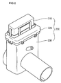
- Fig. 2 is a perspective view of a lint filter assembly according to the present invention
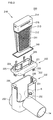
- Fig. 3 is an exploded perspective view of the lint filter assembly depicted in Fig. 2.
- the lint filter assembly 200 includes a filter unit 210 to collect lint, a filter housing 230 in which the filter unit 210 is inserted, and a filter cover 230 coupled to a top of the filter housing 230 to prevent air leakage between the filter unit 210 and the filter housing 230.
- the lint filter assembly 200 is installed in the cabinet 103 above the tub 160 as shown in Fig. 1.
- the lint filter assembly 200 installed in the cabinet 103 is tilted toward the front of the washing machine 100 at a predetermined angle, such that a use can easily detach the filter unit 210 and repair the lint filter assembly 200 from the front of the washing machine 100.
- the lint filter assembly 200 includes one end connected to the air-vent hose 151 and the other end connected to the air-vent duct 300, such that a moist air from the tub 160 during a heat drying operation can be discharged to the outside after passing through the lint filter assembly 200.
- the filter unit 210 includes the filter 211, a filter frame 212 to hold the filter 211, and a handgrip 214 on the filter frame 212 for a use to hold it.
- the filter 211 is made of material having a number of fine holes that are densely formed, such as a mesh.
- the handgrip 214 defines a seal groove 213 having a predetermine depth at its lower periphery to receive a seal 240.
- a securing structure is formed at the filter unit 210 and/or the filter cover 220 to secure the filter unit 210 to the filter cover 220.
- the handgrip 214 includes protruded coupling ribs 215 around its vertical surfaces for coupling with coupling hooks 226 of the filter cover 220.
- the number or shape of the coupling ribs 215 is not limited to the illustrated construction.
- the number of the coupling ribs 215 may be coincident with the number of the coupling hooks 226.
- the filter housing 230 defines an upwardly opened chamber therein to receive the filter unit 210.
- the filter cover 220 is coupled on the upwardly opened chamber to provide tight sealing between the filter housing 230 and the filter unit 210.
- the filter housing 230 includes an air inlet 233 at one side for connection with the air-vent hose 151, an air outlet 234 extendedly from the other side for connection with the air-vent duct 300, a nozzle 232 spaced apart from the air outlet 234, and at least one hooking protrusion 231 formed around an upper periphery for securing the filter cover 220.
- the nozzle 232 is connected to the water inlet hose 180 through a connecting tube (refer to 250 in Fig. 4) branched off from the water inlet hose 180, such that water can be injected at a high pressure into the filter housing 230 through the nozzle 232 during a heat drying operation. The injected water strikes the filter 211 to remove build-up of lint from the filter 211.
- the nozzle 232 will be more fully described later.
- the filter housing 230 includes guide ribs 235 at each inner side face to guide the insertion of the filter unit 210.
- the guide ribs 235 are formed in a vertical direction and spaced apart from each other according to the width of the filter frame 212 to exactly receive the filter unit 210.
- the filter housing 230 includes a supporting protrusion (refer to 236 in Fig. 4) at an inner bottom to support a lower end of the filter frame 212 without shaking.
- the shape of the filter cover 220 is corresponding to the top of the filter housing 230.
- the filter cover 220 includes a cover body 221, a filter inserting slot 224 defined in the cover body 221 for the insertion of the filter unit 210, a filter supporting rib 225 extended upwardly along the periphery of the filter inserting slot 224, one or more coupling hooks 226 extended upwardly from the filter supporting rib 225, and coupling tabs 222 extended downwardly from the bottom of the cover body 221.
- the filter supporting rib 225 supports the periphery of the handgrip 214 of the filter unit 210, such that the handgrip 214 can be fixed without shaking.
- the coupling hooks 226 are hooked on the coupling ribs 215 formed on vertical surfaces of the handgrip 214. That is, the filter unit 210 and the filter cover 220 can be securely coupled by the coupling hooks 226.
- Each of the coupling tabs 222 extended downwardly from the bottom of the cover body 221, defines a coupling hole 223 for coupling with the hooking protrusion 231 formed around the upper periphery of the filter housing 230, such that the filter cover 220 can securely couple with the filter housing 230.
- the filter cover 220 is formed with the coupling tabs 222 each defining the coupling hole 223 and the filter housing 230 is formed with the hooking protrusion 231.
- another securing structure can be formed at the filter cover 220 and/or the filter housing 230 to secure the filter cover 220 to the filter housing 230.
- the seal 240 which is inserted in the seal groove 213 of the handgrip 210, makes tight contact with the inner surface of the filter inserting slot 224 of the filter housing 220 to prevent air leakage from the filter housing 230.
- a moist air generated in the tub 160 during a heat drying operation is introduced into the filter housing 230 through the air inlet 233 and passes through the filter 211.
- lint is removed from the moist air by the filter 211.
- the moist air further flows toward the air-vent duct 300 through the air outlet 234 and then discharged to the outside of the washing machine 100.
- the nozzle 232 water is injected into the filter housing 230. The injected water strikes the filter 211 from the back to remove build-up of lint from the filter 211, and the removed lint drops down on the inner bottom of the filter housing 230.
- the dropped lint is moved toward the tub 160 through the air inlet 233 and the air-vent hose 151 by the injected water. Also, the injected water as it flows through the air-vent hose 151 wipes out lint deposited on a pleated inner surface of the air-vent hose 151, thereby cleaning the air-vent hose 151.
- Fig. 4 is an enlarged cut-away view of the portion encircled by line "A" in Fig. 1.
- the lint filter assembly 200 is installed between the air-vent hose 151 and the air-vent duct 300, and the connecting tube 250 branched off from the water inlet hose 180 is connected to the nozzle 232.
- An on/off valve 260 may be installed between the water inlet hose 180 and the connecting tube 250, in order to close the connecting tube 250 when water is supplied to the tub 160 and close the water inlet hose 180 when a heat drying operation is carried out. That is, during the heat drying operation, the water inlet hose 180 is closed by the on/off valve 260, such that water is not supplied to the tub 160 through the detergent dispenser drawer 120.
- a pressure booster may be installed in the connecting tube 250 to increase the pressure of the water to inject water more strongly through the nozzle 232.
- an end of the connecting tube 250 can be directly connected to the filter housing 230.
- the lint filter assembly 200 may be preferably made of heat resistant material.
- the filter unit 210 is designed to be easily detached and inserted from and into the filter cover 220, a user can manually clean the filter 211 after opening the top plate 101 and pulling the filter unit 210 out.
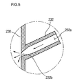
- Fig. 5 is an enlarged view sectional view of the portion encircled by line "B" in Fig. 3.
- the nozzle 232 formed on the filter housing 230 is designed to inject water into the filter hosing 230.
- the nozzle 232 includes a nozzle inlet 232a connected to the connecting tube 250 branched off from the water inlet hose 180. Also, the nozzle 232 includes a nozzle outlet 232b directed toward the inside of the filter housing 230 to inject water into the filter housing 230.
- the nozzle outlet 232b is designed to have a diameter smaller than the nozzle inlet 232a to increase water injection pressure and spread the injecting water toward the filter 211.
- the water injected from the nozzle 232 clearly removes build-up of lint from the filter 211.
Abstract
Description
- The present invention relates to a washing machine, and more particularly, to a drum type washing machine combined with a dryer, in which a lint filter assembly is provided to collect and remove foreign substances such as lint generated during a heat drying operation.
- A washing machine is a home appliance for washing clothes automatically. A typical washing machine uses an electric motor as a driving unit to agitate clothes together with water containing detergent to remove dirt from the clothes. The washing process of the washing machine generally includes washing, rinsing, spin-drying, and/or heat-drying operations.
- Washing machines can be classified into a drum type washing machine, an agitator type washing machine, and a pulsator type washing machine.
- The drum type washing machine includes a plurality of lifters inside of a drum to lift up and drop down clothes in the drum as the drum is rotated about a horizontal axis at a low speed. Therefore, the clothes can be cleaned by the collision with water containing detergent.
- Meanwhile, a washing machine combined with a dryer is recently introduced to satisfy user's demand. In this washing machine, clothes are heat dried after washed, rinsed, and spin dried.
- The washing machine combined with the dryer can be classified into a condenser type and a vented type depending on a drying method.
- The washing machine combined with the condenser type dryer removes residual moisture from clothes by circulating air through a drum, a heat exchanger, and a heater without discharging the air out of the washing machine until the heat drying operation is completed. That is, the air becomes moist after passing through the drum, the moist air cools down at the heat exchanger by exchanging heat with a cooling water, the moisture in the air condenses and drops down to the bottom of the tub as the moist air cools down, and the air is heated again by the heater and then enters the drum again.
- In the washing machine combined with the vented type dryer, on the contrary, a heated dry air is blew into a drum to take moisture from clothes and then the air containing lots of moisture is discharged out of the washing machine through a connecting pipe connected between a tub and a vent duct.
- However, the moist air, which is discharged from the washing machine combined with the vented type dryer, contains lint such as fluff, thereby contaminating the indoor air.
- Further, the lint in the moist air, though it is light, falls down and builds up while it is discharged from the tub to the outside through the vent duct. Particularly, the lint builds up on a pleated surface of the connecting pipe connected between the tub and the vent duct. The build-up of the lint becomes bigger according to the time of use, blocking the vent duct. Further, the build-up of the lint increases the possibility of fire. Therefore, there is an increasing need for a structure that can remove the problems related to the lint.
- Accordingly, the present invention is directed to a washing machine combined with a dryer that substantially obviates one or more problems due to limitations and disadvantages of the related art.
- An object of the present invention is to provide a washing machine combined with a vented type dryer, in which an air-vent line, including an air-vent hose connected between a tub and the air-vent duct, is prevented from being plugged by lint generated during a heat drying operation.
- Another object of the present invention is to provide a washing machine combined with a dryer, in which lint generated during a heat drying operation is prevented from building up in an air-vent line and therefore the possibility of fire reduces.
- A further another object of the present invention is to provide a washing machine combined with a dryer that has a lint filter assembly to remove lint, the lint filter assembly being designed such that a user can easily install and replace it.
- Additional advantages, objects, and features of the invention will be set forth in part in the description which follows and in part will become apparent to those having ordinary skill in the art upon examination of the following or may be learned from practice of the invention. The objectives and other advantages of the invention may be realized and attained by the structure particularly pointed out in the written description and claims hereof as well as the appended drawings.
- To achieve these objects and other advantages and in accordance with the purpose of the invention, as embodied and broadly described herein, there is provided a washing machine combined with a dryer, including: a cabinet; a tub installed in the cabinet; an air-vent hose installed to an outer surface of the tub; a lint filter assembly having one end connected to the air-vent hose to remove lint from air discharged from the tub; and an air-vent duct connected to the other end of the lint filter assembly.
- In another aspect of the present invention, there is provided a washing machine combined with a dryer, including: a tub provided with an air-vent hose at an outer surface; a water inlet hose to supply water to the tub; a filter housing including an air inlet connected to the air-vent hose, an air outlet to discharge air introduced from the air inlet, and a nozzle to inject water into the filter housing; a filter cover to cover a top of the filter housing; and a filter unit inserted into the filter housing through the filter cover.
- In a further another aspect of the present invention, there is provided a washing machine combined with a dryer, including: a tub; a water inlet hose to supply water to the tub; and a lint filter assembly including a filter housing having a chamber for passing a moist air discharged from the tub therethrough, a filter cover to cover a top of the filter housing, and a filter unit inserted into the filter housing through the filter cover.
- According to the present invention, the lint generated during the heat drying operation is separated and collected from the moist air before the moist air is discharged to the outside, thereby preventing the indoor air from contamination.
- Further, the water from the water inlet hose is injected toward filter at a high pressure to remove the lint from the filter and direct the removed lint to the bottom of the tub, thereby reducing manual filter cleaning.
- Further, the filter unit is removably installed such that a use can easily clean the filter, thereby preventing the lint from blocking the filter and the air vent passage.
- Further, the filter is removably installed to allow manual cleaning in addition to the automatic cleaning by the water injection, thereby reducing the possibility of fire due to the combination of hot air from the tub and the build-up of lint on the filter.
- It is to be understood that both the foregoing general description and the following detailed description of the present invention are exemplary and explanatory and are intended to provide further explanation of the invention as claimed.
- The accompanying drawings, which are included to provide a further understanding of the invention and are incorporated in and constitute a part of this application, illustrate embodiment(s) of the invention and together with the description serve to explain the principle of the invention. In the drawings:
- Fig. 1 is a sectional view of a washing machine combined with a dryer, in which a lint filter assembly is provided according to the present invention;
- Fig. 2 is a perspective view of a lint filter assembly according to the present invention;
- Fig. 3 is an exploded perspective view of the lint filter assembly depicted in Fig. 2;
- Fig. 4 is an enlarged cut-away view of the portion encircled by line "A" in Fig. 1; and
- Fig. 5 is an enlarged view sectional view of the portion encircled by line "B" in Fig. 3.
- Reference will now be made in detail to the preferred embodiments of the present invention, examples of which are illustrated in the accompanying drawings.
- Fig. 1 is a sectional view of a washing machine combined with a dryer, in which a lint filter assembly is provided according to the present invention.
- Referring to Fig. 1, a washing machine combined with a
dryer 100 includes: an enclosingcabinet 103; atop plate 101 mounted on a top of thecabinet 103; abase plate 102 installed on a bottom of thecabinet 103; afront cover 105 mounted on a front of thecabinet 103; adoor 114 rotatably installed at a center of thefront cover 105; acontrol panel 111 installed at an upper portion of thefront cover 105, thecontrol panel 111 having a plurality of input buttons and a display; adetergent dispenser drawer 120 inserted into a side of thecontrol panel 111 to receive detergent or fabric softener. - Further, the washing machine combined with the
dryer 100 includes a tub 160 installed in thecabinet 103 to receive water (or mixture of water and detergent), adrum 140 installed in the tub 160 to receive clothes, and a drivingmotor 170 mounted on a back of the tub 160 to rotate thedrum 140. Thedriving motor 170 includes ashaft 171 connected to a rear of thedrum 140. Thedrum 140 defines a plurality ofholes 141 to receive water from the tub 160. - Further, the washing machine combined with the
dryer 100 includes adryer duct 130 installed between thecabinet 103 and a top of the tub 160 to introduce a surrounding air into the tub 160, an air-vent hose 151 connected to a top rear of the tub 160 to vent a moist air from thedrum 140 to the outside, and alint filter assembly 200 removably installed in the air-vent hose 151 to remove lint from the moist air passing therethrough during a heat drying operation. Herein, the term "lint" is used to refer to little pieces of thread and fluff, dust, and other particles that are contained in the air passing through thelint filter assembly 200. - The
lint filter assembly 200 has one end connected to the tub 160 and the other end connected to an air-vent duct 300. Thedryer duct 130 includes ablower fan 132 installed therein to draw air and aheater 131 to apply heat to the drawn air. - Further, the washing machine combined with the
dryer 100 includes awater drain tube 190 of which one end is connected to a bottom of the tub 160 to discharge water contaminated during a washing operation or a rinsing operation, awater drain pump 191 connected to the other end of thewater drain tube 190 to pump out the contaminated water, and awater drain hose 192 to discharge the contaminated water pumped by thewater drain pump 191 to the outside. - Further, the washing machine combined with the
dryer 100 includes awater inlet hose 180 and abellows 125. Thewater inlet hose 180 is connected to thedetergent dispenser drawer 120 to supply water to thedetergent dispenser drawer 120, and thebellows 125 connected between thedetergent dispenser drawer 120 and a top of the tub 160 to supply the water mixed with the detergent to the tub 160. - An operation of the washing machine combined with the
dryer 100 will now be described. - First, a user opens the
door 114, loads clothes in thedrum 140 through the openeddoor 114, and closes thedoor 114. Next, the user pulls out thedetergent dispenser drawer 120 to fill it with detergent and fabric softener. Then, the user selects operating conditions using thecontrol panel 111 and presses a start button on thecontrol panel 111. - Upon the pressing of the start button of the
control panel 111, water is supplied to thedetergent dispenser drawer 120 through thewater inlet hose 180. The water mixed with the detergent (washing water) enters the tub 160 through thebellows 125 connected between thedetergent dispenser drawer 120 and the tub 160. The water is supplied until the tub 160 is filled with the water to a predetermined level. After the water is filled, the drivingmotor 170 drives thedrum 140 to carry out a washing operation. - During the washing operation, the clothes and the washing water is lifted up by the rotation of the
drum 140 and then dropped down. By these up and down motions and the detergent, the dirt can be removed from the clothes during the washing operation. - After the washing operation is carried out for a set time, the washing water contaminated is discharged and fresh water is supplied to the tub 160 to carry out a rinsing operation. In detail, when the contaminated water is discharged, the driving
motor 170 is stopped and thewater drain pump 191 is operated to drain the contaminated water from the tub 160 through thewater drain tube 190. The contaminated water is dumped by thewater drain pump 191 toward thewater drain hose 192. Then, the fresh water (rinsing water) is supplied to the tub 160 for the rinsing operation. - Further, a spin drying operation is carried out after the rinsing operation to remove residual water from the clothes, and then a heat drying operation is optionally carried out.
- In the heat drying operation, the
blower fan 132 installed in thedryer duct 130 is driven to draw in a surrounding air from between thecabinet 103 and the tub 160. Theheater 131 applies heat to the drawn-in air, and the heated air is directed into the tub 160 along thedryer duct 130. The heated air flows from the tub 160 into thedrum 140 through the plurality ofholes 141 defined in thedrum 140. The heated air, having a low humidity, takes moisture from the clothes and therefore it becomes a moist air. Then, the moist air is discharged to the outside of thewashing machine 100 through air-vent hose 151, thelint filter assembly 200, and the air-vent duct 300. - Here, the
lint filter assembly 200 collects lint from the moist air passing therethrough. The collected lint builds up on a filter (refer to 211 in Fig. 3) of thelint filter assembly 200, and the build-up of the lint is removed from thefilter 211 by injecting water from thewater inlet line 180 to thefilter 211. The removed lint is directed into the tub 160 through the air-vent hose 151. - The structure of the
lint filter assembly 200 and method of removing the lint with thelint filter assembly 200 will now be described in detail with reference to the accompanying drawings. - Fig. 2 is a perspective view of a lint filter assembly according to the present invention, and Fig. 3 is an exploded perspective view of the lint filter assembly depicted in Fig. 2.
- Referring to Figs. 2 and 3, the
lint filter assembly 200 includes afilter unit 210 to collect lint, afilter housing 230 in which thefilter unit 210 is inserted, and afilter cover 230 coupled to a top of thefilter housing 230 to prevent air leakage between thefilter unit 210 and thefilter housing 230. - The
lint filter assembly 200 is installed in thecabinet 103 above the tub 160 as shown in Fig. 1. Thelint filter assembly 200 installed in thecabinet 103 is tilted toward the front of thewashing machine 100 at a predetermined angle, such that a use can easily detach thefilter unit 210 and repair thelint filter assembly 200 from the front of thewashing machine 100. Thelint filter assembly 200 includes one end connected to the air-vent hose 151 and the other end connected to the air-vent duct 300, such that a moist air from the tub 160 during a heat drying operation can be discharged to the outside after passing through thelint filter assembly 200. - The
filter unit 210 includes thefilter 211, afilter frame 212 to hold thefilter 211, and ahandgrip 214 on thefilter frame 212 for a use to hold it. Thefilter 211 is made of material having a number of fine holes that are densely formed, such as a mesh. Thehandgrip 214 defines aseal groove 213 having a predetermine depth at its lower periphery to receive aseal 240. Also, a securing structure is formed at thefilter unit 210 and/or thefilter cover 220 to secure thefilter unit 210 to thefilter cover 220. For example, thehandgrip 214 includes protrudedcoupling ribs 215 around its vertical surfaces for coupling with coupling hooks 226 of thefilter cover 220. Here, the number or shape of thecoupling ribs 215 is not limited to the illustrated construction. For example, the number of thecoupling ribs 215 may be coincident with the number of the coupling hooks 226. - The
filter housing 230 defines an upwardly opened chamber therein to receive thefilter unit 210. Thefilter cover 220 is coupled on the upwardly opened chamber to provide tight sealing between thefilter housing 230 and thefilter unit 210. - Further, the
filter housing 230 includes anair inlet 233 at one side for connection with the air-vent hose 151, anair outlet 234 extendedly from the other side for connection with the air-vent duct 300, anozzle 232 spaced apart from theair outlet 234, and at least one hookingprotrusion 231 formed around an upper periphery for securing thefilter cover 220. Thenozzle 232 is connected to thewater inlet hose 180 through a connecting tube (refer to 250 in Fig. 4) branched off from thewater inlet hose 180, such that water can be injected at a high pressure into thefilter housing 230 through thenozzle 232 during a heat drying operation. The injected water strikes thefilter 211 to remove build-up of lint from thefilter 211. Thenozzle 232 will be more fully described later. - Further, the
filter housing 230 includesguide ribs 235 at each inner side face to guide the insertion of thefilter unit 210. Theguide ribs 235 are formed in a vertical direction and spaced apart from each other according to the width of thefilter frame 212 to exactly receive thefilter unit 210. Also, thefilter housing 230 includes a supporting protrusion (refer to 236 in Fig. 4) at an inner bottom to support a lower end of thefilter frame 212 without shaking. - The shape of the
filter cover 220 is corresponding to the top of thefilter housing 230. - The
filter cover 220 includes acover body 221, afilter inserting slot 224 defined in thecover body 221 for the insertion of thefilter unit 210, afilter supporting rib 225 extended upwardly along the periphery of thefilter inserting slot 224, one or more coupling hooks 226 extended upwardly from thefilter supporting rib 225, andcoupling tabs 222 extended downwardly from the bottom of thecover body 221. - The
filter supporting rib 225 supports the periphery of thehandgrip 214 of thefilter unit 210, such that thehandgrip 214 can be fixed without shaking. The coupling hooks 226 are hooked on thecoupling ribs 215 formed on vertical surfaces of thehandgrip 214. That is, thefilter unit 210 and thefilter cover 220 can be securely coupled by the coupling hooks 226. - Each of the
coupling tabs 222, extended downwardly from the bottom of thecover body 221, defines acoupling hole 223 for coupling with the hookingprotrusion 231 formed around the upper periphery of thefilter housing 230, such that thefilter cover 220 can securely couple with thefilter housing 230. To secure thefilter cover 220 to thefilter housing 230, thefilter cover 220 is formed with thecoupling tabs 222 each defining thecoupling hole 223 and thefilter housing 230 is formed with the hookingprotrusion 231. However, another securing structure can be formed at thefilter cover 220 and/or thefilter housing 230 to secure thefilter cover 220 to thefilter housing 230. - The
seal 240, which is inserted in theseal groove 213 of thehandgrip 210, makes tight contact with the inner surface of thefilter inserting slot 224 of thefilter housing 220 to prevent air leakage from thefilter housing 230. - In operation, a moist air generated in the tub 160 during a heat drying operation is introduced into the
filter housing 230 through theair inlet 233 and passes through thefilter 211. As the moist air passes through thefilter 211, lint is removed from the moist air by thefilter 211. After passing through thefilter 211, the moist air further flows toward the air-vent duct 300 through theair outlet 234 and then discharged to the outside of thewashing machine 100. Meanwhile, through thenozzle 232, water is injected into thefilter housing 230. The injected water strikes thefilter 211 from the back to remove build-up of lint from thefilter 211, and the removed lint drops down on the inner bottom of thefilter housing 230. The dropped lint is moved toward the tub 160 through theair inlet 233 and the air-vent hose 151 by the injected water. Also, the injected water as it flows through the air-vent hose 151 wipes out lint deposited on a pleated inner surface of the air-vent hose 151, thereby cleaning the air-vent hose 151. - Fig. 4 is an enlarged cut-away view of the portion encircled by line "A" in Fig. 1.
- Referring to Fig. 4, the
lint filter assembly 200 is installed between the air-vent hose 151 and the air-vent duct 300, and the connectingtube 250 branched off from thewater inlet hose 180 is connected to thenozzle 232. - An on/off
valve 260 may be installed between thewater inlet hose 180 and the connectingtube 250, in order to close the connectingtube 250 when water is supplied to the tub 160 and close thewater inlet hose 180 when a heat drying operation is carried out. That is, during the heat drying operation, thewater inlet hose 180 is closed by the on/offvalve 260, such that water is not supplied to the tub 160 through thedetergent dispenser drawer 120. - Further, a pressure booster may be installed in the connecting
tube 250 to increase the pressure of the water to inject water more strongly through thenozzle 232. Also, instead of forming thenozzle 232 on thefilter housing 230, an end of the connectingtube 250 can be directly connected to thefilter housing 230. - Further, since the moist air passing through the
lint filter assembly 200 is hot, thelint filter assembly 200 may be preferably made of heat resistant material. - Further, since the
filter unit 210 is designed to be easily detached and inserted from and into thefilter cover 220, a user can manually clean thefilter 211 after opening thetop plate 101 and pulling thefilter unit 210 out. - Fig. 5 is an enlarged view sectional view of the portion encircled by line "B" in Fig. 3.
- Referring to Fig. 5, the
nozzle 232 formed on thefilter housing 230 is designed to inject water into the filter hosing 230. - In detail, the
nozzle 232 includes anozzle inlet 232a connected to the connectingtube 250 branched off from thewater inlet hose 180. Also, thenozzle 232 includes anozzle outlet 232b directed toward the inside of thefilter housing 230 to inject water into thefilter housing 230. Thenozzle outlet 232b is designed to have a diameter smaller than thenozzle inlet 232a to increase water injection pressure and spread the injecting water toward thefilter 211. - Therefore, the water injected from the
nozzle 232 clearly removes build-up of lint from thefilter 211. - It will be apparent to those skilled in the art that various modifications and variations can be made in the present invention. Thus, it is intended that the present invention covers the modifications and variations of this invention provided they come within the scope of the appended claims and their equivalents.
Claims (23)
- A washing machine combined with a dryer, comprising:a cabinet;a tub installed in the cabinet;an air-vent hose installed to an outer surface of the tub;a lint filter assembly having one end connected to the air-vent hose to remove lint from air discharged from the tub; andan air-vent duct connected to the other end of the lint filter assembly.
- The washing machine according to claim 1, further comprising:a water inlet hose disposed in the cabinet to supply water to the tub from an outside water source; anda connecting tube branched off from the water inlet hose and connected to the lint filter assembly.
- The washing machine according to claim 2, wherein the lint filter assembly is formed with a nozzle at a predetermined side, the nozzle being connected with the connecting tube.
- The washing machine according to claim 1, wherein the lint filter assembly includes:a filter unit to remove the lint from the air;a filter housing to accommodate the filter unit;a filter cover to cover a top of the filter housing; anda seal fitted around the filter unit.
- The washing machine according to claim 4, wherein the filter unit is detachable from the filter housing.
- The washing machine according to claim 4, wherein the filter unit includes a mesh made of heat resistant material for durability against a high-temperature air passing therethrough.
- The washing machine according to claim 4, wherein the filter cover defines a filter inserting slot into which the filter unit is inserted, and the seal fitted around the filter unit makes tight contact with an inner surface of the filter inserting slot.
- The washing machine according to claim 1, wherein the lint filter assembly is installed to be titled toward a front of the washing machine at a predetermined angle.
- A washing machine combined with a dryer, comprising:a tub provided with an air-vent hose at an outer surface;a water inlet hose to supply water to the tub;a filter housing including an air inlet connected to the air-vent hose, an air outlet to discharge air introduced from the air inlet, and a nozzle to inject water into the filter housing;a filter cover to cover a top of the filter housing; anda filter unit inserted into the filter housing through the filter cover.
- The washing machine according to claim 9, wherein the filter unit includes:a mesh type filter;a filter frame formed around the filter to hold the filter; anda handgrip extended from a top of the filter frame.
- The washing machine according to claim 10, wherein the handgrip includes:a seal groove around a lower periphery with a predetermined depth; anda seal fitted around the seal groove.
- The washing machine according to claim 9, wherein the handgrip includes at least one coupling rib protruded from an outer surface, and the filter cover includes at least one coupling hook extended upwardly from a top thereof to couple with the coupling rib.
- The washing machine according to claim 9, wherein the filter cover includes:a filter inserting slot defined in a top with a predetermined size to receive the filter unit; anda filter supporting rib extended upwardly along a periphery of the filter inserting slot with a predetermined height to support the filter unit.
- The washing machine according to claim 9, wherein the filter housing includes a hooking protrusion protruded from an upper periphery, and the filter cover includes a coupling tab extended from a bottom thereof with a predetermined length, the coupling tab defining a coupling hole to receive the hooking protrusion.
- The washing machine according to claim 9, wherein the filter housing includes:a guide rib at an inner side face with a predetermined length to guide the insertion of the filter unit; anda supporting protrusion formed at an inner bottom to support a lower end of the filter unit.
- The washing machine according to claim 9, further comprising a connecting tube branched off from the water inlet hose for connection with the nozzle.
- The washing machine according to claim 16, wherein the connecting tube includes an on/off valve therein to selectively open and close water flow of the water inlet hose.
- The washing machine according to claim 9, wherein the nozzle is located toward a rear of the filter unit.
- The washing machine according to claim 9, wherein the inside diameter of the nozzle narrows toward the filter housing.
- The washing machine according to claim 9, wherein the air inlet and the air outlet of the filter housing are formed in opposite directions to each other.
- A washing machine combined with a dryer, comprising:a tub;a water inlet hose to supply water to the tub; anda lint filter assembly including a filter housing having a chamber for passing a moist air discharged from the tub therethrough, a filter cover to cover a top of the filter housing, and a filter unit inserted into the filter housing through the filter cover.
- The washing machine according to claim 21, wherein the filter housing includes:an air inlet to introduce the moist air discharged from the tub;an air outlet to discharge the moist air out of the filter housing; anda nozzle protruded from a side.
- The washing machine according to claim 22, wherein the nozzle is connected to the water inlet hose.
Applications Claiming Priority (1)
| Application Number | Priority Date | Filing Date | Title |
|---|---|---|---|
| KR1020040104076A KR100700793B1 (en) | 2004-12-10 | 2004-12-10 | Lint filter assembly of drum type washing machine for having dry function |
Publications (2)
| Publication Number | Publication Date |
|---|---|
| EP1669487A1 true EP1669487A1 (en) | 2006-06-14 |
| EP1669487B1 EP1669487B1 (en) | 2016-03-23 |
Family
ID=35925213
Family Applications (1)
| Application Number | Title | Priority Date | Filing Date |
|---|---|---|---|
| EP05291433.0A Active EP1669487B1 (en) | 2004-12-10 | 2005-07-01 | Washing machine combined with dryer |
Country Status (5)
| Country | Link |
|---|---|
| US (1) | US7412853B2 (en) |
| EP (1) | EP1669487B1 (en) |
| KR (1) | KR100700793B1 (en) |
| CN (1) | CN1786328B (en) |
| AU (1) | AU2005203176B8 (en) |
Cited By (16)
| Publication number | Priority date | Publication date | Assignee | Title |
|---|---|---|---|---|
| EP1936022A1 (en) * | 2006-12-22 | 2008-06-25 | Electrolux Home Products Corporation N.V. | Clothes tumble dryer |
| WO2009015919A1 (en) * | 2007-08-01 | 2009-02-05 | Imat S.P.A. | Arrangement for automatically cleaning air filters for a clothes drying machine |
| EP2039819A1 (en) * | 2007-09-21 | 2009-03-25 | CANDY S.p.A. | Washer-drier machine |
| EP2072660A1 (en) * | 2007-12-18 | 2009-06-24 | BSH Bosch und Siemens Hausgeräte GmbH | Household device for caring for pieces of laundry and method for removing fluff |
| WO2013125794A1 (en) | 2012-02-22 | 2013-08-29 | Lg Electronics Inc. | Laundry treating machine |
| EP2695986A2 (en) * | 2011-04-05 | 2014-02-12 | LG Electronics Inc. | Laundry machine and method for cleaning lint filter of laundry machine |
| JP2015511852A (en) * | 2012-02-29 | 2015-04-23 | エルジー エレクトロニクス インコーポレイティド | Clothing processing equipment |
| EP3015594A1 (en) * | 2014-10-28 | 2016-05-04 | LG Electronics Inc. | Laundry treating apparatus |
| EP3135805A1 (en) * | 2015-08-31 | 2017-03-01 | BSH Hausgeräte GmbH | Laundry dryer |
| EP3176313A1 (en) * | 2009-05-28 | 2017-06-07 | LG Electronics Inc. | Laundry machine having a drying function |
| US9828715B2 (en) | 2009-05-28 | 2017-11-28 | Lg Electronics Inc. | Laundry maching having a drying function |
| US9909249B2 (en) | 2014-10-28 | 2018-03-06 | Lg Electronics Inc. | Laundry treating apparatus |
| EP3333307A4 (en) * | 2015-08-04 | 2019-01-16 | LG Electronics Inc. | Laundry treating apparatus |
| EP3312334A4 (en) * | 2015-06-18 | 2019-02-20 | LG Electronics Inc. | Clothes-handling apparatus having drying function |
| EP2227583B1 (en) * | 2007-12-18 | 2019-09-04 | BSH Hausgeräte GmbH | Cleaning device for a component loaded with lint in a household appliance, and method for cleaning a component loaded with lint |
| EP3995614A1 (en) * | 2020-11-10 | 2022-05-11 | Whirlpool Corporation | Combination washer/dryer with a lint screen |
Families Citing this family (50)
| Publication number | Priority date | Publication date | Assignee | Title |
|---|---|---|---|---|
| KR100738714B1 (en) * | 2004-12-10 | 2007-07-12 | 엘지전자 주식회사 | Drum type washing machine for having dry function |
| DE102005013051A1 (en) * | 2005-03-18 | 2006-09-21 | BSH Bosch und Siemens Hausgeräte GmbH | Condensation Dryer |
| US7913419B2 (en) * | 2005-12-30 | 2011-03-29 | Whirlpool Corporation | Non-tumble clothes dryer |
| DE102007007354B4 (en) * | 2006-02-20 | 2013-10-10 | Lg Electronics Inc. | Clothes dryer and method of control |
| KR101253150B1 (en) * | 2006-04-17 | 2013-04-10 | 엘지전자 주식회사 | clothes drier and controlling methode for the same |
| KR100826535B1 (en) * | 2007-02-20 | 2008-05-02 | 엘지전자 주식회사 | Filter cleaning apparatus and ductless dryer having the same |
| KR101348718B1 (en) | 2007-03-06 | 2014-01-10 | 엘지전자 주식회사 | Apparatus for collecting foreign materials and washing machine having the same |
| KR101360205B1 (en) * | 2007-03-06 | 2014-02-12 | 엘지전자 주식회사 | Apparatus for collecting foreign materials and washing machine having the same |
| KR101348719B1 (en) | 2007-03-06 | 2014-01-16 | 엘지전자 주식회사 | Apparatus for collecting foreign materials |
| KR101441917B1 (en) * | 2007-03-06 | 2014-09-29 | 엘지전자 주식회사 | Apparatus for collecting foreign materials and washing machine having the same |
| KR101432585B1 (en) * | 2007-03-06 | 2014-08-22 | 엘지전자 주식회사 | Apparatus for collecting foreign materials and method for cleaning the same |
| DE102007016074A1 (en) * | 2007-04-03 | 2008-10-09 | BSH Bosch und Siemens Hausgeräte GmbH | Method and device for cleaning a component, in particular an evaporator of a condenser device, and laundry or tumble dryer with such a device |
| DE102007049061A1 (en) * | 2007-10-12 | 2009-04-16 | BSH Bosch und Siemens Hausgeräte GmbH | Method and device for cleaning a component, in particular an evaporator of a condenser device, and laundry or tumble dryer with such a device |
| DE102008032800A1 (en) | 2008-07-11 | 2010-01-14 | BSH Bosch und Siemens Hausgeräte GmbH | Device for cleaning a component, in particular an evaporator of a capacitor device |
| DE102008041998A1 (en) * | 2008-09-11 | 2010-03-18 | BSH Bosch und Siemens Hausgeräte GmbH | Dryer with a lint filter and a cleaning device |
| DE102008055086A1 (en) * | 2008-12-22 | 2010-06-24 | BSH Bosch und Siemens Hausgeräte GmbH | Clothes drying apparatus and method for cleaning a screen |
| KR101603106B1 (en) * | 2009-03-03 | 2016-03-14 | 엘지전자 주식회사 | Washing machine |
| DE102009001548A1 (en) * | 2009-03-13 | 2010-09-16 | BSH Bosch und Siemens Hausgeräte GmbH | A laundry drying apparatus having a lint filter disposed within a process air cycle and method of operating the laundry dryer |
| DE102009046683A1 (en) * | 2009-11-13 | 2011-05-19 | BSH Bosch und Siemens Hausgeräte GmbH | Device for cleaning a component of a dryer, dryer with such a device and method for cleaning a component of a dryer |
| US9546444B2 (en) * | 2009-11-13 | 2017-01-17 | Arcelik Anonim Sirketi | Washing machine wherein the unbalanced load is balanced |
| DE102009047155A1 (en) * | 2009-11-26 | 2011-06-01 | BSH Bosch und Siemens Hausgeräte GmbH | Condensate collector for a clothes dryer and clothes dryer with a condensate collector |
| KR101314625B1 (en) * | 2011-08-02 | 2013-10-07 | 엘지전자 주식회사 | Clothes Treating Apparatus |
| DE102011082892A1 (en) * | 2011-09-16 | 2013-03-21 | BSH Bosch und Siemens Hausgeräte GmbH | Method for cleaning lint filter of laundry drying apparatus e.g. tumble dryer, involves supplying processing air to lint filter during drying laundry, and flushing lint filter by cleaning fluid during supplying processing air |
| BR112014003742B1 (en) * | 2012-04-06 | 2021-07-06 | Lg Electronics Inc. | washing machine |
| KR101498081B1 (en) * | 2012-04-06 | 2015-03-03 | 엘지전자 주식회사 | Laundry machine |
| WO2013151345A2 (en) | 2012-04-06 | 2013-10-10 | Lg Electronics Inc. | Laundry machine and method for controlling the same |
| JP6043952B2 (en) * | 2012-08-01 | 2016-12-14 | パナソニックIpマネジメント株式会社 | Clothes dryer |
| US9103589B2 (en) * | 2012-09-27 | 2015-08-11 | Lowell R. Sullivan | Clothes dryer exhaust device |
| DE102012223436A1 (en) * | 2012-12-17 | 2014-06-18 | BSH Bosch und Siemens Hausgeräte GmbH | Household laundry drying machine with lint filter cleaning device |
| US9416475B2 (en) * | 2013-03-26 | 2016-08-16 | Haier Us Appliance Solutions, Inc. | Air flow in a washing machine appliance |
| CN105088703B (en) * | 2014-05-22 | 2019-08-27 | 青岛海尔滚筒洗衣机有限公司 | A kind of line bits filter structure and washing-drying integral machine and control method |
| EP3234255B1 (en) * | 2014-12-16 | 2019-05-15 | Electrolux Appliances Aktiebolag | Laundry drying apparatus with a filter system |
| WO2016108101A1 (en) * | 2014-12-30 | 2016-07-07 | Indesit Company S.P.A. | Washing/drying machine with a device for cleaning an air filter |
| US9725845B2 (en) | 2015-04-15 | 2017-08-08 | Whirlpool Corporation | Laundry treating appliance lint filter |
| KR101691807B1 (en) * | 2015-08-18 | 2017-01-02 | 엘지전자 주식회사 | A controlling method of device for treating laundry |
| CN105803725B (en) * | 2016-05-26 | 2018-03-09 | 孙有芬 | Large commercial dries washing all-in-one machine |
| KR102604236B1 (en) * | 2016-06-23 | 2023-11-21 | 엘지전자 주식회사 | Laundry drying apparatus |
| KR102656144B1 (en) * | 2016-12-23 | 2024-04-11 | 삼성전자주식회사 | Washing machine |
| JP6952489B2 (en) * | 2017-04-20 | 2021-10-20 | 日立グローバルライフソリューションズ株式会社 | Filter cleaning mechanism and cloth drying device using it |
| CN108729104B (en) * | 2017-04-25 | 2021-05-11 | 青岛海尔洗衣机有限公司 | Drying system of washing machine and washing machine |
| WO2018196766A1 (en) * | 2017-04-25 | 2018-11-01 | 青岛海尔洗衣机有限公司 | Drying system of washing machine, and washing machine |
| CN108729106A (en) * | 2017-04-25 | 2018-11-02 | 青岛海尔洗衣机有限公司 | The drying system and washing machine of washing machine |
| CN108729105A (en) * | 2017-04-25 | 2018-11-02 | 青岛海尔洗衣机有限公司 | The drying system and washing machine of washing machine |
| CN108729170B (en) * | 2017-04-25 | 2021-05-11 | 青岛海尔洗衣机有限公司 | Drying system of washing machine and washing machine |
| CN108797055B (en) * | 2017-04-28 | 2021-08-10 | 无锡小天鹅电器有限公司 | Heat pump drain pan and washing machine |
| CN109750471B (en) * | 2017-11-03 | 2021-04-06 | 青岛海尔洗涤电器有限公司 | Automatic abluent filter equipment and clothing treatment facility |
| CN111304889B (en) * | 2018-11-27 | 2022-08-26 | 青岛海尔洗涤电器有限公司 | Clothes treatment equipment |
| CN112442836B (en) * | 2019-08-29 | 2023-03-03 | 松下家电(中国)有限公司 | Thread scrap processing method of clothes processing equipment |
| US11452964B2 (en) * | 2020-03-04 | 2022-09-27 | Whirlpool Corporation | Water spray feature of an appliance for separating particulate material from a filter member |
| WO2022142252A1 (en) * | 2020-12-31 | 2022-07-07 | 无锡小天鹅电器有限公司 | Air supply assembly and laundry treatment device |
Citations (8)
| Publication number | Priority date | Publication date | Assignee | Title |
|---|---|---|---|---|
| US4204339A (en) * | 1978-02-17 | 1980-05-27 | August Lepper, Maschinen-U. Apparatebau GmbH | Tumbler washing and drying machine |
| US4653200A (en) * | 1986-03-05 | 1987-03-31 | Whirlpool Corporation | Lint screen shield assembly for a dryer |
| GB2219652A (en) * | 1988-06-10 | 1989-12-13 | Servis Group Limited | Water-rinsed lint filter |
| EP0501747A1 (en) * | 1991-02-28 | 1992-09-02 | Hitachi, Ltd. | Washing and drying machine |
| GB2287476A (en) * | 1994-03-01 | 1995-09-20 | Miele & Cie | Washer-drier |
| EP0816549A2 (en) * | 1996-06-26 | 1998-01-07 | CANDY S.p.A. | Domestic washing machine having a closed drying circuit, air condensation of vapour and self cleaning filter |
| EP1353004A1 (en) * | 2002-04-09 | 2003-10-15 | Bonferraro S.p.A. | Washing machine with self-cleaning drying circuit |
| JP2004261324A (en) * | 2003-02-28 | 2004-09-24 | Sanyo Electric Co Ltd | Laundry apparatus |
Family Cites Families (17)
| Publication number | Priority date | Publication date | Assignee | Title |
|---|---|---|---|---|
| US2825148A (en) * | 1955-06-09 | 1958-03-04 | Einer C Olson | Lint trap for laundry drier |
| US2893135A (en) * | 1957-04-08 | 1959-07-07 | Maytag Co | Unitary tub washer-drier |
| US2959044A (en) * | 1959-03-23 | 1960-11-08 | Gen Electric | Lint filter for combination washer-dryer |
| US3220230A (en) * | 1964-02-24 | 1965-11-30 | Gen Motors Corp | Washer and dryer with means in the washer for removing lint from the dryer |
| US3292347A (en) * | 1964-12-16 | 1966-12-20 | Ametek Inc | Dust and lint disposal apparatus |
| US3639998A (en) * | 1970-05-21 | 1972-02-08 | Whirlpool Co | Filter condition indicator |
| ES242354Y (en) * | 1979-03-16 | 1979-11-16 | DRYING DEVICE FOR CLOTHES WASHING MACHINES. | |
| US4700492A (en) * | 1986-02-05 | 1987-10-20 | Whirlpool Corporation | Air actuated automatic lint screen cleaning system for dryer |
| US5143528A (en) * | 1990-02-14 | 1992-09-01 | Challenge Industries | Lint collector |
| FR2678960B1 (en) * | 1991-07-10 | 1993-10-29 | Ardam | PROCESS AND DEVICE FOR REMOVING BUTTER DEPOSITS IN THE HOT AIR PRODUCTION CIRCUIT OF WASHING AND DRYING MACHINES. |
| US5628122A (en) * | 1994-10-05 | 1997-05-13 | Peter And Theordore Spinardi Investments | Lint remover for a clothes drying machine |
| US5741340A (en) * | 1995-08-18 | 1998-04-21 | Klemmer; Roland | Air venting unit |
| JP2002200395A (en) * | 2002-01-08 | 2002-07-16 | Toshiba Corp | Washing/drying machine |
| US7168274B2 (en) * | 2003-05-05 | 2007-01-30 | American Dryer Corporation | Combination washer/dryer having common heat source |
| WO2005032322A2 (en) * | 2003-09-29 | 2005-04-14 | Self Propelled Research And Development Specialists, Llc | Heat pump clothes dryer |
| KR20060031164A (en) * | 2004-10-07 | 2006-04-12 | 엘지전자 주식회사 | Drum type washing machine for having dry function |
| KR20060040352A (en) * | 2004-11-05 | 2006-05-10 | 엘지전자 주식회사 | Lint filter assembly of drum type washing machine for having dry function |
-
2004
- 2004-12-10 KR KR1020040104076A patent/KR100700793B1/en active IP Right Grant
-
2005
- 2005-07-01 EP EP05291433.0A patent/EP1669487B1/en active Active
- 2005-07-18 US US11/184,420 patent/US7412853B2/en not_active Expired - Fee Related
- 2005-07-20 AU AU2005203176A patent/AU2005203176B8/en not_active Ceased
- 2005-07-21 CN CN2005100874035A patent/CN1786328B/en active Active
Patent Citations (8)
| Publication number | Priority date | Publication date | Assignee | Title |
|---|---|---|---|---|
| US4204339A (en) * | 1978-02-17 | 1980-05-27 | August Lepper, Maschinen-U. Apparatebau GmbH | Tumbler washing and drying machine |
| US4653200A (en) * | 1986-03-05 | 1987-03-31 | Whirlpool Corporation | Lint screen shield assembly for a dryer |
| GB2219652A (en) * | 1988-06-10 | 1989-12-13 | Servis Group Limited | Water-rinsed lint filter |
| EP0501747A1 (en) * | 1991-02-28 | 1992-09-02 | Hitachi, Ltd. | Washing and drying machine |
| GB2287476A (en) * | 1994-03-01 | 1995-09-20 | Miele & Cie | Washer-drier |
| EP0816549A2 (en) * | 1996-06-26 | 1998-01-07 | CANDY S.p.A. | Domestic washing machine having a closed drying circuit, air condensation of vapour and self cleaning filter |
| EP1353004A1 (en) * | 2002-04-09 | 2003-10-15 | Bonferraro S.p.A. | Washing machine with self-cleaning drying circuit |
| JP2004261324A (en) * | 2003-02-28 | 2004-09-24 | Sanyo Electric Co Ltd | Laundry apparatus |
Non-Patent Citations (1)
| Title |
|---|
| PATENT ABSTRACTS OF JAPAN vol. 2003, no. 12 5 December 2003 (2003-12-05) * |
Cited By (34)
| Publication number | Priority date | Publication date | Assignee | Title |
|---|---|---|---|---|
| EP1936022A1 (en) * | 2006-12-22 | 2008-06-25 | Electrolux Home Products Corporation N.V. | Clothes tumble dryer |
| WO2009015919A1 (en) * | 2007-08-01 | 2009-02-05 | Imat S.P.A. | Arrangement for automatically cleaning air filters for a clothes drying machine |
| EP2039819A1 (en) * | 2007-09-21 | 2009-03-25 | CANDY S.p.A. | Washer-drier machine |
| EP2072660A1 (en) * | 2007-12-18 | 2009-06-24 | BSH Bosch und Siemens Hausgeräte GmbH | Household device for caring for pieces of laundry and method for removing fluff |
| EP2227583B1 (en) * | 2007-12-18 | 2019-09-04 | BSH Hausgeräte GmbH | Cleaning device for a component loaded with lint in a household appliance, and method for cleaning a component loaded with lint |
| US9828715B2 (en) | 2009-05-28 | 2017-11-28 | Lg Electronics Inc. | Laundry maching having a drying function |
| EP3176313A1 (en) * | 2009-05-28 | 2017-06-07 | LG Electronics Inc. | Laundry machine having a drying function |
| US9487906B2 (en) | 2011-04-05 | 2016-11-08 | Lg Electronics Inc. | Laundry machine and method for cleaning lint filter of laundry machine |
| EP2695986A2 (en) * | 2011-04-05 | 2014-02-12 | LG Electronics Inc. | Laundry machine and method for cleaning lint filter of laundry machine |
| EP2695986A4 (en) * | 2011-04-05 | 2014-09-03 | Lg Electronics Inc | Laundry machine and method for cleaning lint filter of laundry machine |
| EP2817445A4 (en) * | 2012-02-22 | 2015-10-28 | Lg Electronics Inc | Laundry treating machine |
| US9441883B2 (en) | 2012-02-22 | 2016-09-13 | Lg Electronics Inc. | Laundry treating machine |
| WO2013125794A1 (en) | 2012-02-22 | 2013-08-29 | Lg Electronics Inc. | Laundry treating machine |
| RU2596463C2 (en) * | 2012-02-22 | 2016-09-10 | ЭлДжи ЭЛЕКТРОНИКС ИНК. | Laundry treating machine |
| AU2013223005B2 (en) * | 2012-02-22 | 2016-03-03 | Lg Electronics Inc. | Laundry treating machine |
| JP2015511852A (en) * | 2012-02-29 | 2015-04-23 | エルジー エレクトロニクス インコーポレイティド | Clothing processing equipment |
| US9909249B2 (en) | 2014-10-28 | 2018-03-06 | Lg Electronics Inc. | Laundry treating apparatus |
| EP3015594A1 (en) * | 2014-10-28 | 2016-05-04 | LG Electronics Inc. | Laundry treating apparatus |
| US9677215B2 (en) | 2014-10-28 | 2017-06-13 | Lg Electronics Inc. | Laundry treating apparatus |
| EP3312334A4 (en) * | 2015-06-18 | 2019-02-20 | LG Electronics Inc. | Clothes-handling apparatus having drying function |
| US10815610B2 (en) | 2015-06-18 | 2020-10-27 | Lg Electronics Inc. | Clothes treating apparatus having drying function |
| US11932984B2 (en) | 2015-06-18 | 2024-03-19 | Lg Electronics Inc. | Clothes treating apparatus having drying function |
| US11421373B2 (en) | 2015-06-18 | 2022-08-23 | Lg Electronics Inc. | Clothes treating apparatus having drying function |
| US11326300B2 (en) | 2015-06-18 | 2022-05-10 | Lg Electronics Inc. | Clothes treating apparatus having drying function |
| EP3647481A1 (en) * | 2015-06-18 | 2020-05-06 | LG Electronics Inc. | Clothes treating apparatus having drying function |
| EP3647480A1 (en) * | 2015-06-18 | 2020-05-06 | LG Electronics Inc. | Clothes treating apparatus having drying function |
| US10661214B2 (en) | 2015-08-04 | 2020-05-26 | Lg Electronics Inc. | Laundry treating apparatus |
| EP3666965A1 (en) * | 2015-08-04 | 2020-06-17 | LG Electronics Inc. | Laundry treating apparatus |
| EP3333307A4 (en) * | 2015-08-04 | 2019-01-16 | LG Electronics Inc. | Laundry treating apparatus |
| CN106480684B (en) * | 2015-08-31 | 2019-09-20 | 博西华电器(江苏)有限公司 | Dryer |
| EP3135805A1 (en) * | 2015-08-31 | 2017-03-01 | BSH Hausgeräte GmbH | Laundry dryer |
| CN106480684A (en) * | 2015-08-31 | 2017-03-08 | 博西华电器(江苏)有限公司 | Dryer |
| EP3995614A1 (en) * | 2020-11-10 | 2022-05-11 | Whirlpool Corporation | Combination washer/dryer with a lint screen |
| US11807973B2 (en) | 2020-11-10 | 2023-11-07 | Whirlpool Corporation | Combination washer/dryer with a lint screen |
Also Published As
| Publication number | Publication date |
|---|---|
| US7412853B2 (en) | 2008-08-19 |
| CN1786328B (en) | 2011-07-06 |
| KR100700793B1 (en) | 2007-03-27 |
| US20060123854A1 (en) | 2006-06-15 |
| AU2005203176B2 (en) | 2008-05-01 |
| AU2005203176B8 (en) | 2008-05-15 |
| CN1786328A (en) | 2006-06-14 |
| KR20060065266A (en) | 2006-06-14 |
| AU2005203176A1 (en) | 2006-06-29 |
| EP1669487B1 (en) | 2016-03-23 |
Similar Documents
| Publication | Publication Date | Title |
|---|---|---|
| US7412853B2 (en) | Washing machine combined with dryer | |
| US20060096335A1 (en) | Washing machine combined with dryer | |
| EP1669488B1 (en) | Washing machine combined with dryer | |
| KR101203552B1 (en) | Detergent applying apparatus of cleaning device | |
| AU2005203177B8 (en) | Washing machine combined with dryer and controlling method thereof | |
| US7836733B2 (en) | Laundry machine and lint filter thereof | |
| KR100688779B1 (en) | Drum type washing and drying machine | |
| KR101203554B1 (en) | Detergent applying apparatus of cleaning device | |
| US20060086001A1 (en) | Washing machine combined with dryer | |
| KR20110009918A (en) | A laundry treatment machine | |
| JP6295424B2 (en) | Washing and drying machine | |
| JP2009225871A (en) | Washing machine | |
| KR101155336B1 (en) | Water applying method of commercial cleaning device | |
| KR101203555B1 (en) | Commercial cleaning apparatus | |
| CN109629168B (en) | Washing and drying machine | |
| KR200396933Y1 (en) | Dryer | |
| KR20110009924A (en) | A laundry treatment machine | |
| KR101155483B1 (en) | Detergent applying apparatus of cleaning device | |
| KR101155484B1 (en) | Detergent applying apparatus of cleaning device | |
| KR101263863B1 (en) | Top plate mounting structure of cleaning apparatus | |
| KR200399775Y1 (en) | Commercial cleaning apparatus | |
| KR100418898B1 (en) | Pulsator type washing machine having drying function | |
| KR100418897B1 (en) | Pulsator type washing machine having drying function | |
| KR20080056847A (en) | Steam laundry dryer | |
| KR20070015279A (en) | Drying method of commercial drying machine |
Legal Events
| Date | Code | Title | Description |
|---|---|---|---|
| PUAI | Public reference made under article 153(3) epc to a published international application that has entered the european phase |
Free format text: ORIGINAL CODE: 0009012 |
|
| AK | Designated contracting states |
Kind code of ref document: A1 Designated state(s): AT BE BG CH CY CZ DE DK EE ES FI FR GB GR HU IE IS IT LI LT LU LV MC NL PL PT RO SE SI SK TR |
|
| AX | Request for extension of the european patent |
Extension state: AL BA HR MK YU |
|
| 17P | Request for examination filed |
Effective date: 20060627 |
|
| 17Q | First examination report despatched |
Effective date: 20060728 |
|
| AKX | Designation fees paid |
Designated state(s): DE FR GB |
|
| RIN1 | Information on inventor provided before grant (corrected) |
Inventor name: HONG, KYUNG SEOP Inventor name: HONG, SOG KIE |
|
| GRAP | Despatch of communication of intention to grant a patent |
Free format text: ORIGINAL CODE: EPIDOSNIGR1 |
|
| INTG | Intention to grant announced |
Effective date: 20150925 |
|
| GRAS | Grant fee paid |
Free format text: ORIGINAL CODE: EPIDOSNIGR3 |
|
| GRAA | (expected) grant |
Free format text: ORIGINAL CODE: 0009210 |
|
| AK | Designated contracting states |
Kind code of ref document: B1 Designated state(s): DE FR GB |
|
| REG | Reference to a national code |
Ref country code: GB Ref legal event code: FG4D |
|
| REG | Reference to a national code |
Ref country code: DE Ref legal event code: R096 Ref document number: 602005048710 Country of ref document: DE |
|
| REG | Reference to a national code |
Ref country code: FR Ref legal event code: PLFP Year of fee payment: 12 |
|
| REG | Reference to a national code |
Ref country code: DE Ref legal event code: R097 Ref document number: 602005048710 Country of ref document: DE |
|
| PLBE | No opposition filed within time limit |
Free format text: ORIGINAL CODE: 0009261 |
|
| STAA | Information on the status of an ep patent application or granted ep patent |
Free format text: STATUS: NO OPPOSITION FILED WITHIN TIME LIMIT |
|
| 26N | No opposition filed |
Effective date: 20170102 |
|
| REG | Reference to a national code |
Ref country code: FR Ref legal event code: PLFP Year of fee payment: 13 |
|
| PGFP | Annual fee paid to national office [announced via postgrant information from national office to epo] |
Ref country code: GB Payment date: 20170608 Year of fee payment: 13 |
|
| REG | Reference to a national code |
Ref country code: FR Ref legal event code: PLFP Year of fee payment: 14 |
|
| GBPC | Gb: european patent ceased through non-payment of renewal fee |
Effective date: 20180701 |
|
| PG25 | Lapsed in a contracting state [announced via postgrant information from national office to epo] |
Ref country code: GB Free format text: LAPSE BECAUSE OF NON-PAYMENT OF DUE FEES Effective date: 20180701 |
|
| PGFP | Annual fee paid to national office [announced via postgrant information from national office to epo] |
Ref country code: FR Payment date: 20220607 Year of fee payment: 18 |
|
| PGFP | Annual fee paid to national office [announced via postgrant information from national office to epo] |
Ref country code: DE Payment date: 20230607 Year of fee payment: 19 |