EP1669159A1 - Processing nozzle for laser cutting with a nozzle sleeve projection over the work nozzle ; Laser processing device and process with such a work nozzle - Google Patents
Processing nozzle for laser cutting with a nozzle sleeve projection over the work nozzle ; Laser processing device and process with such a work nozzle Download PDFInfo
- Publication number
- EP1669159A1 EP1669159A1 EP04405758A EP04405758A EP1669159A1 EP 1669159 A1 EP1669159 A1 EP 1669159A1 EP 04405758 A EP04405758 A EP 04405758A EP 04405758 A EP04405758 A EP 04405758A EP 1669159 A1 EP1669159 A1 EP 1669159A1
- Authority
- EP
- European Patent Office
- Prior art keywords
- nozzle
- nozzle body
- sleeve
- workpiece
- processing
- Prior art date
- Legal status (The legal status is an assumption and is not a legal conclusion. Google has not performed a legal analysis and makes no representation as to the accuracy of the status listed.)
- Withdrawn
Links
Images


Classifications
-
- B—PERFORMING OPERATIONS; TRANSPORTING
- B23—MACHINE TOOLS; METAL-WORKING NOT OTHERWISE PROVIDED FOR
- B23K—SOLDERING OR UNSOLDERING; WELDING; CLADDING OR PLATING BY SOLDERING OR WELDING; CUTTING BY APPLYING HEAT LOCALLY, e.g. FLAME CUTTING; WORKING BY LASER BEAM
- B23K26/00—Working by laser beam, e.g. welding, cutting or boring
- B23K26/36—Removing material
- B23K26/38—Removing material by boring or cutting
-
- B—PERFORMING OPERATIONS; TRANSPORTING
- B23—MACHINE TOOLS; METAL-WORKING NOT OTHERWISE PROVIDED FOR
- B23K—SOLDERING OR UNSOLDERING; WELDING; CLADDING OR PLATING BY SOLDERING OR WELDING; CUTTING BY APPLYING HEAT LOCALLY, e.g. FLAME CUTTING; WORKING BY LASER BEAM
- B23K26/00—Working by laser beam, e.g. welding, cutting or boring
- B23K26/02—Positioning or observing the workpiece, e.g. with respect to the point of impact; Aligning, aiming or focusing the laser beam
-
- B—PERFORMING OPERATIONS; TRANSPORTING
- B23—MACHINE TOOLS; METAL-WORKING NOT OTHERWISE PROVIDED FOR
- B23K—SOLDERING OR UNSOLDERING; WELDING; CLADDING OR PLATING BY SOLDERING OR WELDING; CUTTING BY APPLYING HEAT LOCALLY, e.g. FLAME CUTTING; WORKING BY LASER BEAM
- B23K26/00—Working by laser beam, e.g. welding, cutting or boring
- B23K26/12—Working by laser beam, e.g. welding, cutting or boring in a special atmosphere, e.g. in an enclosure
- B23K26/123—Working by laser beam, e.g. welding, cutting or boring in a special atmosphere, e.g. in an enclosure in an atmosphere of particular gases
-
- B—PERFORMING OPERATIONS; TRANSPORTING
- B23—MACHINE TOOLS; METAL-WORKING NOT OTHERWISE PROVIDED FOR
- B23K—SOLDERING OR UNSOLDERING; WELDING; CLADDING OR PLATING BY SOLDERING OR WELDING; CUTTING BY APPLYING HEAT LOCALLY, e.g. FLAME CUTTING; WORKING BY LASER BEAM
- B23K26/00—Working by laser beam, e.g. welding, cutting or boring
- B23K26/12—Working by laser beam, e.g. welding, cutting or boring in a special atmosphere, e.g. in an enclosure
- B23K26/127—Working by laser beam, e.g. welding, cutting or boring in a special atmosphere, e.g. in an enclosure in an enclosure
-
- B—PERFORMING OPERATIONS; TRANSPORTING
- B23—MACHINE TOOLS; METAL-WORKING NOT OTHERWISE PROVIDED FOR
- B23K—SOLDERING OR UNSOLDERING; WELDING; CLADDING OR PLATING BY SOLDERING OR WELDING; CUTTING BY APPLYING HEAT LOCALLY, e.g. FLAME CUTTING; WORKING BY LASER BEAM
- B23K26/00—Working by laser beam, e.g. welding, cutting or boring
- B23K26/14—Working by laser beam, e.g. welding, cutting or boring using a fluid stream, e.g. a jet of gas, in conjunction with the laser beam; Nozzles therefor
- B23K26/1462—Nozzles; Features related to nozzles
- B23K26/1464—Supply to, or discharge from, nozzles of media, e.g. gas, powder, wire
- B23K26/1476—Features inside the nozzle for feeding the fluid stream through the nozzle
Landscapes
- Engineering & Computer Science (AREA)
- Physics & Mathematics (AREA)
- Optics & Photonics (AREA)
- Plasma & Fusion (AREA)
- Mechanical Engineering (AREA)
- Laser Beam Processing (AREA)
Abstract
Description
Die vorliegende Erfindung betrifft eine Bearbeitungsdüse zum Laserschneiden, eine Laserbearbeitungsvorrichtung und ein Laserbearbeitungsverfahren mit einer speziellen Bearbeitungsdüse, insbesondere der nachfolgend beschriebenen Gattung.The present invention relates to a laser cutting machining nozzle, a laser machining apparatus, and a laser machining method having a special machining nozzle, particularly of the type described below.
Beim Vorgang des Schneidens mit einem Laserstrahl - vorzugsweise im Infrarotbereich, nämlich im fernen Infrarotbereich eines CO2-Lasers oder im nahen Infrarotbereich zum Beispiel eines Nd-YAG-Lasers - wird der Laserstrahl üblicherweise durch eine Düse gerichtet, durch die auch ein Schneidgas auf die zu schneidende Oberfläche geleitet wird. Das bei dem Bearbeitungsverfahren des Laserschneidens als Schneidgas bezeichnete Prozessgas dient dem Austreiben des hauptsächlich flüssigen Materials aus der im Bearbeitungsprozess entstehenden Schnittfuge. Die Qualität einer Laserschnittfläche wird wesentlich durch die Einstellung geeigneter Prozessgasströmungen bestimmt. Eine gute Qualität der Schnittfuge ist durch eine geringe und feine Riefenstruktur, durch geringe Rauheit über die gesamte bearbeitete Werkstückfläche, durch fehlenden Grat oder geringe Bartbildung, durch fehlende Unregelmässigkeiten, durch eine gerade Schnittspaltform mit geringen Rechtwinkligkeits- und Neigungstoleranzen gekennzeichnet.In the process of cutting with a laser beam - preferably in the infrared, namely in the far infrared region of a CO 2 laser or in the near infrared region, for example, a Nd-YAG laser - the laser beam is usually directed through a nozzle through which a cutting gas on the to be cut surface is passed. The process gas referred to as a cutting gas in the machining process of laser cutting serves to expel the mainly liquid material from the kerf formed in the machining process. The quality of a laser interface is essentially determined by the setting of suitable process gas flows. A good quality of the kerf is due to a small and fine groove structure, by low roughness over the entire machined workpiece surface, by missing burr or little beard formation, by missing irregularities, by a straight Slit form characterized by low squareness and tilt tolerances.
Ein solches - unter anderem auch als Schutzgas zur Minimierung und Verhinderung von Partikelablagerungen auf den optischen Elementen der Laserstrahlführung verwendetes - Prozessgas wird üblicherweise Stickstoff oder ein anderes inertes Gas oder Gasgemisch oder auch Sauerstoff sein, ist aber nicht darauf beschränkt. Solche Anwendungen sind z.B. in den JP-A-2002-273591, JP-A-10-113786, JP-A-11-216589 beschrieben. Alternativ wurde - z.B. in der DE-A-198 58 684 - auch schon vorgeschlagen, das Schneidgas von aussen auf die Schneidoberfläche zu leiten.Such a process gas used inter alia also as a protective gas for minimizing and preventing particle deposits on the optical elements of the laser beam guide will usually be, but is not limited to, nitrogen or another inert gas or gas mixture or even oxygen. Such applications are e.g. in JP-A-2002-273591, JP-A-10-113786, JP-A-11-216589. Alternatively, - e.g. in DE-A-198 58 684 - also proposed to direct the cutting gas from the outside to the cutting surface.
Bei allen diesen Anwendungen ist von Nachteil, dass ein hoher Schneidgasverbrauch zu verzeichnen ist, wenn die Materialdicke der zu schneidenden Werkstücke zunimmt. Der Prozessgasverbrauch ist ein wesentlicher Kostenfaktor bei Laserbearbeitungsprozessen, insbesondere beim Laserschneiden von dicken Blechen. Die Reduzierung des Verbrauchs bei gleichbleibend hoher Bearbeitungsqualität ist insbesondere dann von Bedeutung, wenn Gase hoher Reinheit oder Edelgase eingesetzt werden müssen.In all these applications is disadvantageous that a high cutting gas consumption is recorded when the material thickness of the workpieces to be cut increases. The consumption of process gas is a significant cost factor in laser processing processes, especially in the laser cutting of thick sheets. The reduction of consumption with consistently high quality machining is particularly important when gases of high purity or noble gases must be used.
Weiterhin ist bei den genannten Anwendungen zu bemängeln, dass der Schneidgasabfluss überwiegend oder zumindest in ganz erheblichem Masse seitlich stattfindet, so dass ein wesentlicher Anteil des Prozessgases nicht effizient in die sich bildende Schnittfuge des Schneidobjektes gelangen kann.Furthermore, it must be complained about in the mentioned applications that the cutting gas outflow predominantly or at least to the greatest extent takes place laterally, so that a substantial portion of the process gas can not efficiently reach the forming kerf of the cutting object.
In der EP-A-1 005 945 wird speziell für das Einstechen beim Laserschneiden vorgeschlagen, eine Vorrichtung mit einem kleinen Schablonenloch zu verwenden, wodurch eine Verschmutzung der optischen Komponenten zur Laserstrahlführung und -formung durch rückspritzende Partikel verhindert werden kann und die Bearbeitungszeit für den Prozess des Einstechens verkürzt werden kann. Für einen Laserbearbeitungsprozess wie dem Laserschneiden erscheint diese spezielle Vorrichtung weniger geeignet, weil sie direkt auf dem Werkstück aufsetzt und eine kontinuierliche Bewegung behindert. Diese spezielle Vorrichtung müsste demontiert werden und schränkt den Einsatz der Düse ein.In EP-A-1 005 945, especially for piercing in laser cutting, it is proposed to use a device having a small stencil hole, whereby staining of the optical components for laser beam guiding and shaping by reprecipitating particles can be prevented and processing time for the process of grooving can be shortened. For a laser processing process such as laser cutting, this particular device appears less suitable because it rests directly on the workpiece and impedes continuous movement. This special device would have to be disassembled and restricts the use of the nozzle.
Im Falle einer Düse, durch die eine grosse Durchflussmenge des Prozessgases für den Laserbearbeitungsprozess geleitet werden muss, wie dies z.B. beim Laserschneiden von dicken Werkstücken auftritt, ist ein möglichst kleiner Düsenabstand vom Schneidobjekt wünschenswert. Damit tritt das Problem auf, dass im Falle von Unebenheiten, insbesondere durch unerwünschte Entstehung von Partikeln während des Einstechens und des Schneidvorganges, die Schneiddüse beschädigt oder in ihrem Fahrweg behindert werden kann. Es wurde bereits vorgeschlagen und eingeführt, durch eine Abstandsregelung den Abstand der Düsenaustrittsöffnung zum Werkstück einzustellen und während des gesamten Bearbeitungsprozesses zu regeln.In the case of a nozzle through which a large flow rate of the process gas for the laser processing process must be passed, as described e.g. When laser cutting thick workpieces occurs, the smallest possible nozzle distance from the object to be cut is desirable. Thus, the problem arises that in the case of bumps, in particular by unwanted formation of particles during piercing and the cutting process, the cutting nozzle can be damaged or obstructed in their travel. It has already been proposed and introduced to adjust the distance of the nozzle outlet opening to the workpiece by a distance control and to regulate during the entire machining process.
Es ist die Aufgabe der Erfindung, eine Laserbearbeitungsdüse bereitzustellen, mit der beim Laserschneiden ein effizienter Schmelzaustrieb aus einer Schnittfuge realisiert werden kann, mit der ein geringerer Schneidgasverbrauch als beim hier angegebenen Stand der Technik notwendig ist und mit der die Qualität der Schnittflächen verbessert wird. Weiterhin ist ein Verfahren zum Laserschneiden mit einer Laserbearbeitungsdüse, insbesondere nach der vorstehend beschriebenen Gattung anzugeben, mit dem ein geringer Schneidgasverbrauch und eine Effizienzsteigerung des Bearbeitungsprozesses hinsichtlich Kostensenkung und Qualitätsverbesserung erzielt werden kann.It is the object of the invention to provide a laser processing nozzle, with the laser cutting an efficient Schmelzaustrieb can be realized from a kerf, with a lower cutting gas consumption than in the state of the art specified here is necessary and with the quality of the cut surfaces is improved. Furthermore, a method for laser cutting with a laser processing nozzle, in particular according to the type described above, with which a low cutting gas consumption and an increase in efficiency of the machining process in terms of cost reduction and quality improvement can be achieved.
Die Erfindung löst die Aufgabe durch eine Einrichtung nach Anspruch 1. Dabei haben die Massnahmen der Erfindung zunächst einmal zur Folge, dass mit einer speziellen Ausführungsform, die Wirksamkeit, der Gasströmung erheblich verbessert werden kann, und dass mit der vorgeschlagenen Bearbeitungsdüse ein kleiner Abstand zu dem zu bearbeitenden Werkstück eingestellt werden kann, so dass der Schneidgasverbrauch erheblich vermindert werden kann. Weiterhin haben die Massnahmen der Erfindung zur Folge, dass das ausströmende Prozessgas effizient zum Austreiben restlicher Schmelze genutzt wird und eine Verschmutzung oder Beschädigung durch im Bearbeitungsprozess entstehende Partikel verhindert wird.The invention achieves the object by a device according to
Mit der Minimierung des Abstandes der Bearbeitungsdüse und der gleichzeitigen Abgrenzung der Umgebung durch die Verwendung einer Düsenhülse gemäss Anspruch 1 wird das seitliche Wegströmen des Prozessgases stark begrenzt und minimiert, in bestimmten Fällen sogar nahezu verhindert. Der Gasstrom wird optimal in die sich bildende Bearbeitungsfuge geführt. Das freie Volumen zwischen Düsenkörper und Düsenhülse ist während des Bearbeitungsprozesses mit dem Prozessgas gefüllt.With the minimization of the distance of the processing nozzle and the simultaneous delimitation of the environment by the use of a nozzle sleeve according to
Die Verbesserung der Prozessgasströmung wurde beim Laserschneiden experimentell beobachtet. Es wurde gefunden, dass insbesondere eine verbesserte Gasströmung entlang des gesamten Schnittspaltes über die gesamte Werkstückdicke, einhergehend mit höheren Strömungsgeschwindigkeiten- insbesondere im unteren Bereich des zu bearbeitenden Werkstückes - hier eines Bleches - zu verzeichnen ist.The improvement of the process gas flow was observed experimentally during laser cutting. It has been found that, in particular, an improved gas flow along the entire kerf over the entire workpiece thickness, accompanied by higher flow velocities - in particular in the lower region of the workpiece to be machined - here a sheet - can be observed.
Ein weiterer Vorteil der Erfindung gemäss Anspruch 1 besteht bei einer bevorzugten Ausführungsform darin, dass bei äusserer Verschmutzung der Düsenhülse nur diese ausgewechselt werden muss. Die einfache Form der Düsenhülse führt zu geringeren Fertigungskosten im Vergleich zu einem auswechselbaren Düsenkörper.Another advantage of the invention according to
Vorteilhaft ist ein Laserbearbeitungsverfahren nach dem unabhängigen Verfahrensanspruch gemäss Anspruch 17, bei dem ein Polster erzeugt wird, das aus dem ausströmenden Prozessgas zwischen Düsenkörperaustrittsöffnung 1a, Düsenhülse 3 und dem zu bearbeitenden Werkstück 5 gebildet wird.Advantageously, a laser processing method according to the independent method claim according to claim 17, in which a pad is generated, which is formed from the effluent process gas between the nozzle body outlet opening 1a,
Weitere vorteilhafte Einzelheiten der Erfindung sind in den abhängigen Ansprüchen dargelegt.Further advantageous details of the invention are set forth in the dependent claims.
Die vorgenannten sowie die beanspruchten und in den nachfolgenden Ausführungsbeispielen beschriebenen, erfindungsgemäss zu verwendenden Elemente unterliegen in ihrer Grösse, Formgestaltung, Materialverwendung und technischen Konzeption keinen besonderen Ausnahmebedingungen, so dass die in dem jeweiligen Anwendungsgebiet bekannten Auswahlkriterien uneingeschränkt Anwendung finden können.The aforementioned and the claimed and described in the following embodiments, according to the invention to be used elements are subject to their size, shape design, material usage and technical design no special conditions of exception, so that the well-known in the respective field of application selection criteria can apply without restriction.
Weitere Einzelheiten, Merkmale und Vorteile des Gegenstandes der Erfindung ergeben sich aus der nachfolgenden Beschreibung der dazugehörigen Zeichnungen, in denen - beispielhaft - eine Bearbeitungsdüse und ein - vorzugsweise entsprechendes Verfahren zur vorliegenden Erfindung erläutert wird.Further details, features and advantages of the subject matter of the invention will become apparent from the following description of the accompanying drawings, in which - by way of example - a processing nozzle and a - preferably corresponding method of the present invention will be explained.
Die Zeichnungen zeigen Schnittbilder:
- Fig. 1
- einer Bearbeitungsdüse in Seitenansicht nach einer Ausführungsform mit einem Halterungs- und Dichtungsmittel in Form eines Dichtungsringes eingelassen in einer im Düsenkörper eingebrachten Nut zur Positionierung einer Düsenhülse auf dem Düsenkörper;
- Fig. 2
- einer Bearbeitungsdüse in Seitenansicht nach einer zweiten Ausführungsform der vorliegenden Erfindung mit einem oberhalb der Düsenhülse angebrachten Po- sitionierungsteil zur Halterung und Positionierung der Düsenhülse bezüglich der Düsenkörperaustrittsöffnung und einem seitlich zwischen Düsenhülse und im Düsenkörper eingelassenen Nut positionierten Dichtungsmittel;
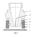
- Fig. 3
- einer Bearbeitungsdüse in Seitenansicht nach einer dritten Ausführungsform der vorliegenden Erfindung mit einem seitlich zwischen Düsenhülse und Düsenkörper angebrachten Dichtungsmittel und einem Positionierungsteil, das in seiner mechanischen Ausführung zur Positionierung der Düsenhülse relativ zur Düsenkörperöffnung in Form einer variablen Positionierung als Klemm-, Spannring oder als Tellerfeder oder Spirale ausgeführt sein kann;
- Fig. 4
- einer Bearbeitungsdüse in Seitenansicht nach einer vierten Ausführungsform der vorliegenden Erfindung mit einem Düsenkörper, in den ein oder mehrere Bohrungen eingebracht wurden, durch die Prozessgas strömen kann, mit einer Nut in die ein Positionierungsteil in Form eines Ringes aufgenommen wird, das als unterer Anschlag für die axial in Richtung des zu bearbeitenden Werkstückes verschiebbare Düsenhülse wirkt;
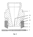
- Fig. 5
- einer Bearbeitungsdüse in Seitenansicht nach einer fünften Ausführungsform mit einem Düsenkörper, in dem sich ein oder mehrere Löcher befinden, mit einem seitlichen Halterungs- und Positionierungsteil zwischen Düsenkörper und Düsenhülse und in der Düsenhülse ausgebildeten weiteren Gasführungsmitteln wie zum Beispiel Bohrungen oder Gaskanälen.
- Fig. 1
- a processing nozzle in side view according to an embodiment with a holding and sealing means in the form of a sealing ring inserted in a groove introduced in the nozzle body for positioning a nozzle sleeve on the nozzle body;
- Fig. 2
- a side view of a processing nozzle according to a second embodiment of the present invention with a mounted above the nozzle sleeve Po sierungsierungsteil for holding and positioning of the nozzle sleeve with respect to the nozzle body outlet opening and a laterally inserted between the nozzle sleeve and the nozzle body groove positioned sealant;
- Fig. 3
- a processing nozzle in side view according to a third embodiment of the present invention with a laterally mounted between the nozzle sleeve and nozzle body sealant and a positioning member, in its mechanical design for positioning the nozzle sleeve relative to the nozzle body opening in the form of a variable positioning as a clamping, clamping ring or plate spring or Spiral can be executed;
- Fig. 4
- a processing nozzle in side view according to a fourth embodiment of the present invention having a nozzle body into which one or more holes have been introduced, can flow through the process gas, with a groove into which a positioning member is received in the form of a ring which serves as a lower stop for the axially displaceable in the direction of the workpiece to be machined nozzle sleeve acts;
- Fig. 5
- a processing nozzle in side view according to a fifth embodiment with a nozzle body in which there are one or more holes, with a lateral support and positioning part between the nozzle body and nozzle sleeve and formed in the nozzle sleeve further gas flow means such as holes or gas channels.
Bei der in Figur 1 dargestellten Bearbeitungsdüse ist der Düsenkörper 1 im unteren Bereich mit einer rotationssymmetrischen Düsenhülse 3 überzogen. Die Düsenhülse 3 ragt dabei über die Austrittöffnung des Düsenkörpers 1 hinaus. Im vorliegenden Ausführungsbeispiel ist die innere Geometrie des Düsenkörper 1 in Nähe der Düsenkörperaustrittsöffnung 1a zylindrisch und im sich anschliessenden Bereich konvergent ausgebildet. In Fig. 1 ist eine Halterung und Positionierung der Düsenhülse mit einem Dichtungsmittel 2 in Form eines Dichtungsringes gezeigt, wobei dieser sich in einer im Düsenkörper eingebracht Nut 1b befindet.In the case of the processing nozzle illustrated in FIG. 1, the
Die Düsenhülse 3 ist mit Hilfe eines Dichtungsmittels 2 zentriert und relativ zur Düsenkörperaustrittsöffnung 1a positioniert. Die vertikale Positionierung der Düsenhülse relativ zum Düsenkörper kann ebenso über das Einbringen einer Nut in der Düsenhülse und mit einem Dichtungsring oder andere bereits bekannte Dichtungsarten erfolgen, wie sie zum Beispiel aus der Vakuumtechnik bekannt sind. Die Verbindung zwischen Düsenkörper und Düsenhülse sollte sowohl einen einfachen Wechsel der Düsenhülse gestatten als auch ein Abgleiten der Düsenhülse vom Düsenkörper während des Bearbeitungsprozesse bei hohen Beschleunigungen und das unerwünscht Ausströmen des Prozessgases in eine andere als die dem Werkstück zugewandten Richtung verhindern.The
Düsenkörper 1 und Düsenhülse 3 bilden einen Hohlraum aus, der zusammen mit dem zu bearbeitenden Werkstück 5 mit dem ausströmenden Prozessgas gefüllt wird. Das Volumen des Hohlraumes kann sehr klein sein. In diesen Raum wird bei der Bearbeitung durch die Düsenaustrittsöffnung sowohl ein Laserstrahl, im Ausführungsbeispiel ein Laserstrahl eines CO2-Lasers als auch ein Prozessgas, im Ausführungsbeispiel Stickstoff als Schneidgas, geleitet.
In dem Ausführungsbeispiel des Laserschneidens wird zur Regelung des Abstandes der Düsenaustrittsöffnung einer Bearbeitungsdüse und einem Werkstück oft eine kapazitiven Abtastung und Regelung verwendet. Es sollte aber betont werden, dass andere Abstandsreglungen oder keine Abstandsreglung (während des Bearbeitungsprozesses konstanter Abstand) bei der Verwendung einer Bearbeitungsdüse zur Laserbearbeitung eines Werkstückes eingesetzt werden können.In the embodiment of laser cutting, capacitive sensing and regulation is often used to control the distance of the nozzle exit orifice of a processing nozzle and a workpiece. But it should be emphasized that other distance controls or no distance control (constant distance during the machining process) can be used when using a machining nozzle for laser machining of a workpiece.
Die hier beschriebene Auslegung der Düsenhülse 3 ist sowohl für Keramiken als auch für metallische Werkstoffe geeignet. Entsprechend ist die Regelungs- und Steuereinrichtung auszulegen, mit der eine Kollision der Düsenhülse 3 mit aufliegenden oder während des Bearbeitungsprozesses entstehenden Spritzern, aufstehenden, geschnittenen Teilen aus dem Werkstück und anderen Hindernissen verhindert wird.The design of the
Die in Figur 2 gezeigte Bearbeitungsdüse unterscheidet sich von der vorstehend beschriebenen Düse dadurch, dass ein weiteres Positionierungsteil 4, in der Ausführung wie ein Klemm- oder Dichtungsring als Positionierung oder/und Halterung der Düsenhülse koaxial zum Laserstrahl und relativ zur Düsenkörperaustrittsöffnung dient. Die innere Geometrie des Düsenkörpers ist durch eine konvergente Form gekennzeichnet.The processing nozzle shown in Figure 2 differs from the nozzle described above in that another
Die in Figur 3 abgebildete Variante der Bearbeitungsdüse ist durch eine aussen angefaste Geometrie der Düsenhülse 3 gekennzeichnet. Die innere Geometrie des Düsenkörpers 1 ist im Bereich der Düsenaustrittsöffnung 1a zylindrisch ausgebildet. Im angrenzenden mittleren Teil des Düsenkörpers ist eine konvergente Geometrie ausgebildet. Das Positionierungsteil 4 oberhalb der Düsenhülse ist dadurch gekennzeichnet, dass eine radiale und/oder vertikale Beweglichkeit der mechanischen Halterung gegeben ist, wie sie zum Beispiel durch die Verwendung einer Tellerfeder, einer Spirale oder Spann-, Klemmringes realisiert werden kann.The variant of the machining nozzle shown in FIG. 3 is characterized by an externally chamfered geometry of the
Die innere Geometrie des Düsenkörpers kann in verschiedenen Ausführungen erfolgen. Die Formen des Düsenkörpers können sowohl einteilige Ausführungen zylindrisch, konvergent, divergent und ihrer Kombinationen sein als auch mehrteilige Ausführungen in Form von Doppeldüsen oder Ringdüsen.The inner geometry of the nozzle body can be done in various designs. The shapes of the nozzle body can be both one-piece designs cylindrical, convergent, divergent and their combinations as well as multi-part designs in the form of double nozzles or ring nozzles.
Die Merkmale der Figuren 1, 2 und 3 können frei miteinander kombiniert werden.The features of Figures 1, 2 and 3 can be freely combined with each other.
In Figur 4 ist eine Bearbeitungsdüse in einer Seitenansicht dargestellt, die sich von der Düse aus Figur 1 dadurch unterscheidet, dass die Düsenhülse axial verschiebbar ausgebildet ist, wobei ein in eine Nut 1b im Düsenkörper 1 eingelassenes Positionierungsteil 2a, wie zum Beispiel ein Klemmring, das Abgleiten der Düsenhülse vom Düsenkörper verhindert. Die Düsenhülse 3 ist nach oben durch eine Auskragung des Düsenkörpers 1 und nach unten durch das Positionierungsteil 2a in seiner axialen Bewegungsfreiheit begrenzt. In diesem Ausführungsbeispiel wird die axiale Bewegung der Düsenhülse mit Hilfe der Wirkung eines durch eine oder mehrere Bohrungen 1c vom Hauptgasstrom abgeleiteten Gasdruckes relativ zum Düsenkörper geregelt. Im vorliegenden Fall kann also der Düsenkörper 1 in einen festen Abstand zum Werkstück gehalten bzw. mit einer Abstandsregelung gesteuert und geregelt werden. Der Abstand der Düsenhülse 3 relativ zur Düsenkörperaustrittsöffnung wird über den Schneidgasdruck, die Anzahl eingebrachter Löcher im Düsenkörper 1c, entsprechend der inneren Geometrie des Düsenkörpers 1, der äusseren Geometrie des unteren Bereiches des Düsenkörpers in Nähe der Düsenkörperaustrittsöffnung, und der inneren Geometrie der Düsenhülse 3 eingestellt. Damit kann auch das Volumen des ausgebildeten Stauraumes unterhalb der Düsenaustrittsöffnung des Düsenkörpers variiert werden.In Figure 4, a processing nozzle is shown in a side view, which differs from the nozzle of Figure 1 differs in that the nozzle sleeve is axially displaceable, with a recessed into a
Die in Figur 5 dargestellte Bearbeitungsdüse unterscheidet sich von der Düse in Figur 4 dadurch, dass in die Düsenhülse 3 zusätzliche Gasführungsmittel in Form von Bohrungen oder Kanälen 3a eingebracht wurden, die zur Ausbildung eines Gasstromes führen, der ringförmig den aus dem Düsenkörper ausströmenden Hauptgasstrom umschliesst. Dadurch wird auf der Werkstückoberfläche eine zusätzliche Gasströmung beaufschlagt, der den Hauptstrahl ringförmig umschliesst.The processing nozzle shown in Figure 5 differs from the nozzle in Figure 4, characterized in that in the
Die Merkmale der Figuren 4 und 5 können frei mit den geometrischen und technischen Merkmalen der vorstehend beschriebenen Ausführung nach Figur 1 bis 3 miteinander kombinieren werden.The features of Figures 4 and 5 can be freely combined with the geometric and technical features of the embodiment of Figures 1 to 3 described above.
- 11
- Düsenkörpernozzle body
- 1a1a
- DüsenkörperaustrittsöffnungNozzle body outlet opening
- 1b1b
- Nutgroove
- 1c1c
- DüsenkörperbohrungNozzle body bore
- 22
- Dichtungs- und HalterungsmittelSealing and holding means
- 2a2a
- Positionierungsteil (z.B. Klemm- oder Sichelring)Positioning part (e.g., pinch or sickle ring)
- 33
- Düsenhülsenozzle sleeve
- 3a3a
- Gasführungsmittel (z.B. Bohrung)Gas guiding means (e.g., bore)
- 44
- Positionierungsteilpositioning member
- 55
- zu bearbeitendes Werkstückworkpiece to be machined
Claims (18)
gekennzeichnet durch
marked by
Priority Applications (1)
| Application Number | Priority Date | Filing Date | Title |
|---|---|---|---|
| EP04405758A EP1669159A1 (en) | 2004-12-07 | 2004-12-07 | Processing nozzle for laser cutting with a nozzle sleeve projection over the work nozzle ; Laser processing device and process with such a work nozzle |
Applications Claiming Priority (1)
| Application Number | Priority Date | Filing Date | Title |
|---|---|---|---|
| EP04405758A EP1669159A1 (en) | 2004-12-07 | 2004-12-07 | Processing nozzle for laser cutting with a nozzle sleeve projection over the work nozzle ; Laser processing device and process with such a work nozzle |
Publications (1)
| Publication Number | Publication Date |
|---|---|
| EP1669159A1 true EP1669159A1 (en) | 2006-06-14 |
Family
ID=34932396
Family Applications (1)
| Application Number | Title | Priority Date | Filing Date |
|---|---|---|---|
| EP04405758A Withdrawn EP1669159A1 (en) | 2004-12-07 | 2004-12-07 | Processing nozzle for laser cutting with a nozzle sleeve projection over the work nozzle ; Laser processing device and process with such a work nozzle |
Country Status (1)
| Country | Link |
|---|---|
| EP (1) | EP1669159A1 (en) |
Cited By (16)
| Publication number | Priority date | Publication date | Assignee | Title |
|---|---|---|---|---|
| WO2007060008A1 (en) * | 2005-11-25 | 2007-05-31 | Trumpf Werkzeugmaschinen Gmbh + Co. Kg | Laser machining nozzle |
| WO2009030209A1 (en) * | 2007-09-03 | 2009-03-12 | Fraunhofer-Gesellschaft zur Förderung der angewandten Forschung e.V. | Device and method for laser beam cutting |
| WO2010053805A1 (en) * | 2008-10-28 | 2010-05-14 | The Boeing Company | Inert gas cover system for laser welding with a base and wall having an opening |
| DE102010029112A1 (en) * | 2010-05-19 | 2011-11-24 | Trumpf Werkzeugmaschinen Gmbh + Co. Kg | Laser-processing of a workpiece with laser processing head, comprises feeding a laser beam and working gas to a processing point of the workpiece by using the laser processing head, and producing a liquid curtain at a side of the workpiece |
| WO2012156608A1 (en) | 2011-05-16 | 2012-11-22 | L'air Liquide,Societe Anonyme Pour L'etude Et L'exploitation Des Procedes Georges Claude | Laser nozzle with mobile element |
| FR2982184A1 (en) * | 2011-11-07 | 2013-05-10 | Air Liquide | LASER NOZZLE WITH MOBILE ELEMENT ON GAS LAYER |
| WO2013150195A1 (en) | 2012-04-04 | 2013-10-10 | L'air Liquide,Societe Anonyme Pour L'etude Et L'exploitation Des Procedes Georges Claude | Laser nozzle with mobile element of improved external profile |
| WO2014072610A1 (en) | 2012-11-09 | 2014-05-15 | L'air Liquide, Societe Anonyme Pour L'etude Et L'exploitation Des Procedes Georges Claude | Laser nozzle having a modular mobile element made of electrically insulating material and an insert made of electrically conductive material |
| WO2014072609A1 (en) | 2012-11-09 | 2014-05-15 | L'air Liquide, Societe Anonyme Pour L'etude Et L'exploitation Des Procedes Georges Claude | Laser nozzle having an external mobile element |
| WO2014072611A1 (en) | 2012-11-09 | 2014-05-15 | L'air Liquide, Societe Anonyme Pour L'etude Et L'exploitation Des Procedes Georges Claude | Laser nozzle having an internal mobile element and an external cover |
| US9088376B2 (en) | 2006-10-18 | 2015-07-21 | Coriant Oy | Method and system for synchronization |
| WO2015170029A1 (en) | 2014-05-06 | 2015-11-12 | L'air Liquide, Societe Anonyme Pour L'etude Et L'exploitation Des Procedes Georges Claude | Nozzle for laser cutting with an internal moveable element and a sleeve with low relative permittivity |
| WO2016177596A1 (en) * | 2015-05-04 | 2016-11-10 | Trumpf Werkzeugmaschinen Gmbh + Co. Kg | Cutting gas nozzle and laser cutting method having a displaceable sleeve for setting the flow characteristics |
| US9744622B2 (en) | 2012-02-16 | 2017-08-29 | Trumpf Laser Gmbh | Moving a laser processing head relative to a clamping claw |
| US10675708B2 (en) | 2016-08-11 | 2020-06-09 | Trumpf Werkzeugmaschinen Gmbh + Co. Kg | Method for laser cutting with optimized gas dynamics |
| DE102019131784A1 (en) * | 2019-11-25 | 2021-05-27 | Precitec Gmbh & Co. Kg | Nozzle for a laser processing device and laser processing device comprising the same |
Citations (9)
| Publication number | Priority date | Publication date | Assignee | Title |
|---|---|---|---|---|
| US4031351A (en) * | 1972-10-25 | 1977-06-21 | Groupement Atomique Alsacienne Atlantique | High energy laser beam cutting method and apparatus |
| JPS6137393A (en) * | 1984-07-30 | 1986-02-22 | Mitsubishi Electric Corp | Laser working machine |
| JPS626790A (en) * | 1985-07-02 | 1987-01-13 | Mitsubishi Electric Corp | Laser beam machining head |
| DE3700190A1 (en) * | 1986-04-16 | 1987-10-29 | Robomatix Ltd | Laser-cutting apparatus and process |
| EP0432521A1 (en) * | 1989-12-09 | 1991-06-19 | Messer Griesheim Gmbh | Method for cutting of materials |
| JPH0768394A (en) * | 1993-09-01 | 1995-03-14 | Kawasaki Heavy Ind Ltd | Cutting condition monitoring device for heat cutting device |
| DE9421369U1 (en) * | 1994-09-23 | 1995-09-14 | Messer Griesheim Schweistechni | Laser machining tool |
| JPH08224688A (en) * | 1995-02-22 | 1996-09-03 | Hitachi Ltd | Underwater machining device |
| JPH11141822A (en) * | 1997-11-07 | 1999-05-28 | Koike Sanso Kogyo Co Ltd | Nozzle for piercing operation |
-
2004
- 2004-12-07 EP EP04405758A patent/EP1669159A1/en not_active Withdrawn
Patent Citations (9)
| Publication number | Priority date | Publication date | Assignee | Title |
|---|---|---|---|---|
| US4031351A (en) * | 1972-10-25 | 1977-06-21 | Groupement Atomique Alsacienne Atlantique | High energy laser beam cutting method and apparatus |
| JPS6137393A (en) * | 1984-07-30 | 1986-02-22 | Mitsubishi Electric Corp | Laser working machine |
| JPS626790A (en) * | 1985-07-02 | 1987-01-13 | Mitsubishi Electric Corp | Laser beam machining head |
| DE3700190A1 (en) * | 1986-04-16 | 1987-10-29 | Robomatix Ltd | Laser-cutting apparatus and process |
| EP0432521A1 (en) * | 1989-12-09 | 1991-06-19 | Messer Griesheim Gmbh | Method for cutting of materials |
| JPH0768394A (en) * | 1993-09-01 | 1995-03-14 | Kawasaki Heavy Ind Ltd | Cutting condition monitoring device for heat cutting device |
| DE9421369U1 (en) * | 1994-09-23 | 1995-09-14 | Messer Griesheim Schweistechni | Laser machining tool |
| JPH08224688A (en) * | 1995-02-22 | 1996-09-03 | Hitachi Ltd | Underwater machining device |
| JPH11141822A (en) * | 1997-11-07 | 1999-05-28 | Koike Sanso Kogyo Co Ltd | Nozzle for piercing operation |
Non-Patent Citations (5)
| Title |
|---|
| PATENT ABSTRACTS OF JAPAN vol. 010, no. 193 (M - 496) 8 July 1986 (1986-07-08) * |
| PATENT ABSTRACTS OF JAPAN vol. 011, no. 175 (M - 596) 5 June 1987 (1987-06-05) * |
| PATENT ABSTRACTS OF JAPAN vol. 1995, no. 06 31 July 1995 (1995-07-31) * |
| PATENT ABSTRACTS OF JAPAN vol. 1997, no. 01 31 January 1997 (1997-01-31) * |
| PATENT ABSTRACTS OF JAPAN vol. 1999, no. 10 31 August 1999 (1999-08-31) * |
Cited By (37)
| Publication number | Priority date | Publication date | Assignee | Title |
|---|---|---|---|---|
| WO2007060008A1 (en) * | 2005-11-25 | 2007-05-31 | Trumpf Werkzeugmaschinen Gmbh + Co. Kg | Laser machining nozzle |
| US9088376B2 (en) | 2006-10-18 | 2015-07-21 | Coriant Oy | Method and system for synchronization |
| WO2009030209A1 (en) * | 2007-09-03 | 2009-03-12 | Fraunhofer-Gesellschaft zur Förderung der angewandten Forschung e.V. | Device and method for laser beam cutting |
| WO2010053805A1 (en) * | 2008-10-28 | 2010-05-14 | The Boeing Company | Inert gas cover system for laser welding with a base and wall having an opening |
| CN102186623A (en) * | 2008-10-28 | 2011-09-14 | 波音公司 | Inert gas cover system for laser welding with a base and wall having an opening |
| US8053701B2 (en) | 2008-10-28 | 2011-11-08 | The Boeing Company | Inert gas cover system for laser welding |
| CN102186623B (en) * | 2008-10-28 | 2014-07-16 | 波音公司 | Inert gas cover system for laser welding with a base and wall having an opening |
| DE102010029112A1 (en) * | 2010-05-19 | 2011-11-24 | Trumpf Werkzeugmaschinen Gmbh + Co. Kg | Laser-processing of a workpiece with laser processing head, comprises feeding a laser beam and working gas to a processing point of the workpiece by using the laser processing head, and producing a liquid curtain at a side of the workpiece |
| US10786868B2 (en) | 2011-05-16 | 2020-09-29 | L'Air Liquide, Société Anonyme pour l'Etude et l'Exploitation des Procédés Georges Claude | Laser nozzle with mobile element |
| WO2012156608A1 (en) | 2011-05-16 | 2012-11-22 | L'air Liquide,Societe Anonyme Pour L'etude Et L'exploitation Des Procedes Georges Claude | Laser nozzle with mobile element |
| US10926352B2 (en) | 2011-05-16 | 2021-02-23 | L'Air Liquide, Société Anonyme pour l'Etude et l'Exploitation des Procédés Georges Claude | Laser nozzle with mobile element |
| WO2013068665A1 (en) | 2011-11-07 | 2013-05-16 | L'air Liquide,Societe Anonyme Pour L'etude Et L'exploitation Des Procedes Georges Claude | Laser nozzle comprising an element movable in a gas layer |
| US10076806B2 (en) | 2011-11-07 | 2018-09-18 | L'Air Liquide, Société Anonyme pour l'Etude et l'Exploitation des Procédés Georges Claude | Laser nozzle comprising an element movable in a gas layer |
| FR2982184A1 (en) * | 2011-11-07 | 2013-05-10 | Air Liquide | LASER NOZZLE WITH MOBILE ELEMENT ON GAS LAYER |
| US9744622B2 (en) | 2012-02-16 | 2017-08-29 | Trumpf Laser Gmbh | Moving a laser processing head relative to a clamping claw |
| WO2013150195A1 (en) | 2012-04-04 | 2013-10-10 | L'air Liquide,Societe Anonyme Pour L'etude Et L'exploitation Des Procedes Georges Claude | Laser nozzle with mobile element of improved external profile |
| EP3300831A1 (en) | 2012-04-04 | 2018-04-04 | L'air Liquide Societe Anonyme Pour L'etude Et L'exploitation Des Procedes Georges Claude | Laser nozzle with mobile element having an improved external profile |
| US9616525B2 (en) | 2012-04-04 | 2017-04-11 | L'Air Liquide, Société Anonyme pour l'Etude et l'Exploitation des Procédés Georges Claude | Laser nozzle with mobile element of improved external profile |
| US9604310B2 (en) | 2012-11-09 | 2017-03-28 | L'Air Liquide, Société Anonyme pour l'Etude et l'Exploitation des Procédés Georges Claude | Laser nozzle having an external mobile element |
| WO2014072611A1 (en) | 2012-11-09 | 2014-05-15 | L'air Liquide, Societe Anonyme Pour L'etude Et L'exploitation Des Procedes Georges Claude | Laser nozzle having an internal mobile element and an external cover |
| WO2014072610A1 (en) | 2012-11-09 | 2014-05-15 | L'air Liquide, Societe Anonyme Pour L'etude Et L'exploitation Des Procedes Georges Claude | Laser nozzle having a modular mobile element made of electrically insulating material and an insert made of electrically conductive material |
| JP2015534905A (en) * | 2012-11-09 | 2015-12-07 | レール・リキード−ソシエテ・アノニム・プール・レテュード・エ・レクスプロワタシオン・デ・プロセデ・ジョルジュ・クロード | Laser nozzle with inner mobile element and outer cover |
| US9844832B2 (en) | 2012-11-09 | 2017-12-19 | L'Air Liquide, Société Anonyme pour l'Etude et l'Exploitation des Procédés Georges Claude | Laser nozzle having an internal mobile element and an external cover |
| US9610652B2 (en) | 2012-11-09 | 2017-04-04 | L'Air Liquide, Société Anonyme pour l'Etude et l'Exploitation des Procédés Georges Claude | Laser nozzle having an external mobile element made of electrically insulating material and an insert made of electrically conductive material |
| WO2014072609A1 (en) | 2012-11-09 | 2014-05-15 | L'air Liquide, Societe Anonyme Pour L'etude Et L'exploitation Des Procedes Georges Claude | Laser nozzle having an external mobile element |
| WO2015170029A1 (en) | 2014-05-06 | 2015-11-12 | L'air Liquide, Societe Anonyme Pour L'etude Et L'exploitation Des Procedes Georges Claude | Nozzle for laser cutting with an internal moveable element and a sleeve with low relative permittivity |
| EP3315246A1 (en) | 2014-05-06 | 2018-05-02 | L'air Liquide Societe Anonyme Pour L'etude Et L'exploitation Des Procedes Georges Claude | Laser nozzle with internal mobile element and nozzle body being made in two parts connected through fixtures |
| EP3315247A1 (en) | 2014-05-06 | 2018-05-02 | L'air Liquide Societe Anonyme Pour L'etude Et L'exploitation Des Procedes Georges Claude | Nozzle for laser cutting with internal mobile element and sleeve having low relative permittivity |
| US10603745B2 (en) | 2015-05-04 | 2020-03-31 | Trumpf Werkzeugmaschinen Gmbh + Co. Kg | Cutting gas nozzle and laser cutting method having a displaceable sleeve for setting the flow characteristics |
| US10751836B2 (en) | 2015-05-04 | 2020-08-25 | Trumpf Werkzeugmaschinen Gmbh + Co. Kg | Gas nozzle having a displaceable valve sleeve |
| WO2016177596A1 (en) * | 2015-05-04 | 2016-11-10 | Trumpf Werkzeugmaschinen Gmbh + Co. Kg | Cutting gas nozzle and laser cutting method having a displaceable sleeve for setting the flow characteristics |
| US11135675B2 (en) | 2015-05-04 | 2021-10-05 | Trumpf Werkzeugmaschinen Gmbh + Co. Kg | Gas nozzle having a displaceable valve sleeve |
| US10675708B2 (en) | 2016-08-11 | 2020-06-09 | Trumpf Werkzeugmaschinen Gmbh + Co. Kg | Method for laser cutting with optimized gas dynamics |
| EP3315243B1 (en) | 2016-08-11 | 2021-09-15 | TRUMPF Werkzeugmaschinen GmbH + Co. KG | Method for laser cutting with optimized gas dynamics |
| DE102016215019C5 (en) | 2016-08-11 | 2023-04-06 | Trumpf Werkzeugmaschinen Gmbh + Co. Kg | Process for laser cutting with optimized gas dynamics |
| DE102019131784A1 (en) * | 2019-11-25 | 2021-05-27 | Precitec Gmbh & Co. Kg | Nozzle for a laser processing device and laser processing device comprising the same |
| WO2021104727A1 (en) | 2019-11-25 | 2021-06-03 | Precitec Gmbh & Co. Kg | Nozzle for a laser machining device and laser machining device comprising same |
Similar Documents
| Publication | Publication Date | Title |
|---|---|---|
| EP1669159A1 (en) | Processing nozzle for laser cutting with a nozzle sleeve projection over the work nozzle ; Laser processing device and process with such a work nozzle | |
| EP0407969B1 (en) | Process and device for manufacturing hollow spaces in workpieces using a laser beam | |
| DE102015208157B4 (en) | Cutting gas nozzle and laser cutting method with sliding valve sleeve for adjusting the flow characteristics | |
| WO2005025781A1 (en) | Substrate sheet for a 3d-shaping method | |
| EP0490935B1 (en) | Device for holding and operating a facing head | |
| DE102006005379A1 (en) | Combination tool and method for machining a borehole and its bore surface and cutting body for such a combination tool | |
| DE4317384A1 (en) | Laser processing head and method for operating the same | |
| WO2009062851A1 (en) | Aerostatic bearing and method for production thereof | |
| DE102012217082B4 (en) | Laser processing head with a ring nozzle | |
| EP3487655A1 (en) | Fsw tool with a stationary shoulder | |
| CH681703A5 (en) | ||
| DE102006047794A1 (en) | Laser arrangement for marking, roughing, hardening and welding the surface of a workpiece, comprises laser source, optical arrangement for focusing and direction controlling of laser beam, supporting area for the workpiece, and window | |
| EP2758202B1 (en) | Reaming tool and method for the production thereof | |
| DE3607580A1 (en) | HONEY DEVICE | |
| DE3937163A1 (en) | WIRE EDM DEVICE | |
| DE10064232C1 (en) | Device and method for guiding a machining electrode in a machine tool, in particular in a wire EDM machine | |
| DE3626808C2 (en) | ||
| DE3942067C2 (en) | Wire guiding device for a spark erosive wire cutting machine | |
| EP2569124A1 (en) | Method for processing an inner face of a housing having an opening | |
| DE3408985C2 (en) | Flushing device for an electrical discharge wire cutting machine | |
| DE1552320A1 (en) | Drilling tool | |
| DE102012025627A1 (en) | Ring nozzle for a laser processing head and laser processing head with it | |
| DE3943652C2 (en) | Spark erosion machine Spark erosion machine | |
| DE102016104543A1 (en) | Apparatus and methods for structuring bearing bores in a storage lane | |
| AT517140A1 (en) | grinding tool |
Legal Events
| Date | Code | Title | Description |
|---|---|---|---|
| PUAI | Public reference made under article 153(3) epc to a published international application that has entered the european phase |
Free format text: ORIGINAL CODE: 0009012 |
|
| AK | Designated contracting states |
Kind code of ref document: A1 Designated state(s): AT BE BG CH CY CZ DE DK EE ES FI FR GB GR HU IE IS IT LI LT LU MC NL PL PT RO SE SI SK TR |
|
| AX | Request for extension of the european patent |
Extension state: AL BA HR LV MK YU |
|
| AKX | Designation fees paid | ||
| REG | Reference to a national code |
Ref country code: DE Ref legal event code: 8566 |
|
| STAA | Information on the status of an ep patent application or granted ep patent |
Free format text: STATUS: THE APPLICATION IS DEEMED TO BE WITHDRAWN |
|
| 18D | Application deemed to be withdrawn |
Effective date: 20061215 |