EP3315246A1 - Laser nozzle with internal mobile element and nozzle body being made in two parts connected through fixtures - Google Patents
Laser nozzle with internal mobile element and nozzle body being made in two parts connected through fixtures Download PDFInfo
- Publication number
- EP3315246A1 EP3315246A1 EP17198493.3A EP17198493A EP3315246A1 EP 3315246 A1 EP3315246 A1 EP 3315246A1 EP 17198493 A EP17198493 A EP 17198493A EP 3315246 A1 EP3315246 A1 EP 3315246A1
- Authority
- EP
- European Patent Office
- Prior art keywords
- nozzle
- nozzle body
- movable element
- axial
- axial housing
- Prior art date
- Legal status (The legal status is an assumption and is not a legal conclusion. Google has not performed a legal analysis and makes no representation as to the accuracy of the status listed.)
- Granted
Links
Images


Classifications
-
- B—PERFORMING OPERATIONS; TRANSPORTING
- B23—MACHINE TOOLS; METAL-WORKING NOT OTHERWISE PROVIDED FOR
- B23K—SOLDERING OR UNSOLDERING; WELDING; CLADDING OR PLATING BY SOLDERING OR WELDING; CUTTING BY APPLYING HEAT LOCALLY, e.g. FLAME CUTTING; WORKING BY LASER BEAM
- B23K26/00—Working by laser beam, e.g. welding, cutting or boring
- B23K26/14—Working by laser beam, e.g. welding, cutting or boring using a fluid stream, e.g. a jet of gas, in conjunction with the laser beam; Nozzles therefor
- B23K26/1462—Nozzles; Features related to nozzles
- B23K26/1464—Supply to, or discharge from, nozzles of media, e.g. gas, powder, wire
- B23K26/1476—Features inside the nozzle for feeding the fluid stream through the nozzle
-
- B—PERFORMING OPERATIONS; TRANSPORTING
- B23—MACHINE TOOLS; METAL-WORKING NOT OTHERWISE PROVIDED FOR
- B23K—SOLDERING OR UNSOLDERING; WELDING; CLADDING OR PLATING BY SOLDERING OR WELDING; CUTTING BY APPLYING HEAT LOCALLY, e.g. FLAME CUTTING; WORKING BY LASER BEAM
- B23K26/00—Working by laser beam, e.g. welding, cutting or boring
- B23K26/14—Working by laser beam, e.g. welding, cutting or boring using a fluid stream, e.g. a jet of gas, in conjunction with the laser beam; Nozzles therefor
- B23K26/1462—Nozzles; Features related to nozzles
- B23K26/1488—Means for protecting nozzles, e.g. the tip surface
-
- B—PERFORMING OPERATIONS; TRANSPORTING
- B23—MACHINE TOOLS; METAL-WORKING NOT OTHERWISE PROVIDED FOR
- B23K—SOLDERING OR UNSOLDERING; WELDING; CLADDING OR PLATING BY SOLDERING OR WELDING; CUTTING BY APPLYING HEAT LOCALLY, e.g. FLAME CUTTING; WORKING BY LASER BEAM
- B23K26/00—Working by laser beam, e.g. welding, cutting or boring
- B23K26/36—Removing material
- B23K26/38—Removing material by boring or cutting
-
- B—PERFORMING OPERATIONS; TRANSPORTING
- B23—MACHINE TOOLS; METAL-WORKING NOT OTHERWISE PROVIDED FOR
- B23K—SOLDERING OR UNSOLDERING; WELDING; CLADDING OR PLATING BY SOLDERING OR WELDING; CUTTING BY APPLYING HEAT LOCALLY, e.g. FLAME CUTTING; WORKING BY LASER BEAM
- B23K37/00—Auxiliary devices or processes, not specially adapted to a procedure covered by only one of the preceding main groups
- B23K37/006—Safety devices
Landscapes
- Engineering & Computer Science (AREA)
- Physics & Mathematics (AREA)
- Optics & Photonics (AREA)
- Mechanical Engineering (AREA)
- Plasma & Fusion (AREA)
- Laser Beam Processing (AREA)
Abstract
La présente demande concerne une buse de coupage laser comprenant un corps (1) de buse comprenant un premier logement axial traversant axialement ledit corps (1) de buse, un orifice d'entrée permettant d'alimenter ledit premier logement axial en gaz d'assistance et un premier orifice de sortie situé au niveau d'une face avant dudit corps de buse (1), et un élément mobile (2) agencé dans le premier logement axial du corps (1) de buse, ledit élément mobile (2) comprenant une partie avant (2a) formant jupe et un passage axial (5) avec un deuxième orifice de sortie (6) débouchant au niveau de ladite partie avant (2a) formant jupe, le corps (1) de buse et l'élément mobile (2) étant formé d'un matériau conducteur électriquement. De plus,le corps (1) de buse est formé d'au moins une première partie (11) agencée autour de l'élément mobile (2) et une deuxième partie (12) venant se positionner, en suivant le sens d'écoulement du gaz d'assistance dans le premier logement axial, au-dessus de ladite première partie (11), le corps (1) de buse comprenant en outre des premiers moyens de fixation (7, 8) aptes à et conçus pour fixer la deuxième partie (12) sur la première partie (11).The present application relates to a laser cutting nozzle comprising a nozzle body (1) comprising a first axial housing axially passing through said nozzle body (1), an inlet orifice making it possible to supply said first axial housing with assist gas. and a first outlet located at a front face of said nozzle body (1), and a movable member (2) arranged in the first axial housing of the nozzle body (1), said movable member (2) comprising a front part (2a) forming a skirt and an axial passage (5) with a second outlet opening (6) opening at the level of said front part (2a) forming a skirt, the body (1) of the nozzle and the movable element ( 2) being formed of an electrically conductive material. In addition, the body (1) of the nozzle is formed of at least a first portion (11) arranged around the movable member (2) and a second portion (12) being positioned, in the direction of flow assist gas in the first axial housing above said first portion (11), the nozzle body (1) further comprising first attachment means (7, 8) adapted to and adapted to secure the second part (12) on the first part (11).
Description
L'invention concerne une buse laser utilisable en coupage laser avec élément mobile interne comprenant une jupe permettant de concentrer le gaz dans la saignée de coupe, la buse offrant une mise en oeuvre au plan industriel améliorée et permettant de préserver la tête de focalisation des effets des chocs que peut subir ladite buse.The invention relates to a laser nozzle that can be used in laser cutting with an internal moving element comprising a skirt for concentrating the gas in the cutting groove, the nozzle offering an improved industrial implementation and making it possible to preserve the focusing head of the effects. shocks that can undergo said nozzle.
Le coupage par faisceau laser nécessite l'utilisation d'une buse généralement en cuivre ayant pour effet de canaliser le gaz et laisser passer le faisceau laser.Laser beam cutting requires the use of a generally copper nozzle having the effect of channeling the gas and passing the laser beam.
Les buses ont typiquement des diamètres de leur orifice de sortie compris entre 0.5 et 3 mm pour une distance de travail comprise entre 0,6 et 2 mm.The nozzles typically have diameters of their outlet orifice of between 0.5 and 3 mm for a working distance of between 0.6 and 2 mm.
Afin de permettre la découpe, il est nécessaire d'utiliser des pressions élevées, en général de plusieurs bar, dans la tête de focalisation afin de permettre au gaz de rentrer dans la saignée pour chasser le métal en fusion.In order to allow the cutting, it is necessary to use high pressures, generally several bar, in the focusing head to allow the gas to enter the groove to drive the molten metal.
Or, une grande partie du gaz utilisée, typiquement entre 50 et 90%, n'a aucune action sur le processus de découpe, c'est-à-dire sur l'expulsion du métal en fusion, car elle part sur les cotés de la saignée de coupe.However, a large part of the gas used, typically between 50 and 90%, has no effect on the cutting process, that is to say on the expulsion of the molten metal, because it leaves on the sides of cutting bleeding.
Ces pertes de gaz sont en fait dues à l'énorme différence entre la section de passage de l'orifice de buse et la taille de la tâche focale. Ainsi, à titre indicatif, la section de passage d'une buse avec orifice de sortie de diamètre égal à 1.5 mm est 25 fois plus importante que la section de la tache focale créée par le faisceau laser traversant cette buse.These losses of gas are in fact due to the enormous difference between the passage section of the nozzle orifice and the size of the focal task. Thus, as an indication, the passage section of a nozzle with an outlet orifice of diameter equal to 1.5 mm is 25 times greater than the section of the focal spot created by the laser beam passing through this nozzle.
Or, si une proportion insuffisante de gaz est mise en oeuvre, on assiste alors à l'apparition de défauts de coupe, en particulier des bavures adhérentes et/ou des traces d'oxydation.However, if an insufficient proportion of gas is used, then there is the appearance of cutting defects, in particular adherent burrs and / or traces of oxidation.
Tenter d'y remédier en réduisant le diamètre de l'orifice de la buse n'est pas idéal car on prend le risque de voir le faisceau laser venir frapper l'intérieur de la buse et la détériorer, ce qui par ailleurs détériore la qualité de coupe et/ou les performances.Attempting to remedy this by reducing the diameter of the orifice of the nozzle is not ideal because we take the risk of seeing the laser beam strike the inside of the nozzle and damage it, which also deteriorates the quality cutting and / or performance.
Il existe par ailleurs un certain nombre de documents proposant diverses solutions pour tenter de favoriser l'entrée du gaz dans la saignée, par exemple
Or, aucune de ces solutions n'est vraiment idéale car souvent d'architecture complexe à mettre en oeuvre, de fonctionnement incompatible avec un usage industriel, et/ou présentant une efficacité limitée.However, none of these solutions is really ideal because often complex architecture to implement, operating incompatible with industrial use, and / or having limited effectiveness.
Notamment, le document
Pour y remédier, le document
Toutefois, cette solution continue de poser certains problèmes.However, this solution continues to pose some problems.
Tout d'abord, la conception de cette buse ne laisse que peu de liberté pour adapter sa géométrie aux différentes têtes de focalisation existant sur le marché, ainsi qu'aux différentes épaisseurs à découper.Firstly, the design of this nozzle leaves little freedom to adapt its geometry to the different focus heads existing on the market, as well as different thicknesses to cut.
Or, l'inventeur de la présente invention a mis en évidence que la découpe des fines épaisseurs, typiquement moins de 3 mm, nécessitait des orifices d'éjection du gaz d'assistance de diamètres plus importants que les diamètres maximaux accessibles avec la buse selon
De plus, les machines industrielles de découpe laser et les têtes de focalisation associées mettent en oeuvre, de façon connue en soi, un système de capteur de distance capacitif pour déplacer la tête à une distance constante au-dessus de la tôle à découper.In addition, the industrial laser cutting machines and the associated focusing heads implement, in a manner known per se, a capacitive distance sensor system for moving the head at a constant distance above the sheet to be cut.
Or, il s'avère que les systèmes de capteur capacitif actuels ne peuvent pas détecter un obstacle latéral s'étendant au-dessus de la surface de la tôle. Un tel obstacle peut résulter par exemple de pièces déjà découpées restées coincées dans la tôle et positionnées en biais par rapport à sa surface. Les découpes débutées à partir d'un bord de tôle peuvent également générer des marches ou dénivelés, c'est-à-dire des différences de niveaux entre différentes parties de la tôle, du fait d'une déformation ou d'un abaissement de certaines parties de la tôle se produisant en cours de découpe.However, it turns out that current capacitive sensor systems can not detect a lateral obstacle extending above the surface of the sheet. Such an obstacle may result, for example, from already cut pieces that have remained wedged in the sheet and positioned at an angle to its surface. Cutouts started from a sheet edge can also generate steps or unevenness, that is to say differences in levels between different parts of the sheet, due to deformation or lowering of certain parts of the sheet occurring during cutting.
Il s'ensuit des risques de chocs au niveau du corps de buse pouvant endommager la buse et en altérer le fonctionnement, jusqu'à entraîner sa rupture ou détérioration complète. L'aspect le plus problématique est qu'un choc au niveau du corps de buse peut aussi endommager la tête de focalisation au niveau de sa connexion avec la buse et entraîner un déplacement de la tête sur son support, ce qui provoque un désalignement du faisceau laser. Il est alors nécessaire d'intervenir sur la tête de focalisation et de procéder à son réalignement, ce qui nuit à la productivité de la machine de découpe.This results in the risk of shocks at the nozzle body that can damage the nozzle and impair its operation, to cause its rupture or complete deterioration. The most problematic aspect is that a shock at the nozzle body can also damage the focusing head at its connection with the nozzle and cause a displacement of the head on its support, which causes a misalignment of the laser beam. It is then necessary to intervene on the focusing head and proceed with its realignment, which affects the productivity of the cutting machine.
Le document
Néanmoins, ceci ne résout pas certains problèmes rencontrés avec la buse selon
Ainsi, un système de capteur de distance capacitif utilise l'effet capacitif pour détecter de faibles variations de distance entre deux éléments conducteurs formant un condensateur. La distance séparant les deux éléments conducteurs est déterminée en mesurant la capacité électrique de ce condensateur, qui dépend notamment de la permittivité diélectrique du milieu qui les sépare.Thus, a capacitive distance sensor system uses the capacitive effect to detect small variations in distance between two conductive elements forming a capacitor. The distance separating the two conductive elements is determined by measuring the capacitance of this capacitor, which depends in particular on the dielectric permittivity of the medium which separates them.
Dans une machine de découpe munie d'une buse laser traditionnelle, généralement formée d'un matériau électriquement conducteur tel du cuivre, le capteur capacitif mesure la capacité électrique entre la tôle et la surface plate de la buse située en regard de la tôle. Le capteur capacitif est relié électriquement aux commandes de déplacements de la tête de focalisation de manière à ajuster le positionnement en hauteur de la tête en cas de variations de la capacité électrique mesurée ou à stopper le déplacement de la tête en cas de contact entre la buse et la tôle.In a cutting machine equipped with a traditional laser nozzle, generally formed of an electrically conductive material such as copper, the capacitive sensor measures the electrical capacitance between the sheet and the flat surface of the nozzle located opposite the sheet. The capacitive sensor is electrically connected to the control commands of the focusing head so as to adjust the height positioning of the head in the event of variations in the measured electrical capacitance or to stop the displacement of the head in the event of contact between the nozzle. and the sheet.
Ce système de capteur capacitif permet d'assurer des performances de coupe constantes, en termes de vitesse et qualité de coupe, en maintenant le point de focalisation du faisceau laser à une position constante par rapport à la surface de la tôle. Il permet aussi de déclencher l'arrêt de la machine en cas d'obstacles présents sur la tôle.This capacitive sensor system ensures consistent cutting performance, in terms of speed and cutting quality, by maintaining the focusing point of the laser beam at a constant position relative to the surface of the sheet. It also allows to trigger the machine stop in case of obstacles on the sheet.
Il est donc indispensable de ne pas perturber son fonctionnement.It is therefore essential not to disturb its operation.
Or, la buse laser décrite dans
En effet, l'élément mobile de la buse forme une jupe en contact avec la tôle à découper. Pour garantir sa résistance à la chaleur dégagée par le procédé de découpe ainsi qu'aux projections de métal fondu, l'élément mobile est en général formé d'un matériau conducteur électriquement tel un matériau métallique (cuivre, laiton ou analogue). Toutefois, l'élément mobile conducteur électriquement est alors à la fois en contact avec la tôle, c'est-à-dire au même potentiel électrique que celle-ci, et en contact avec les parois internes du corps de buse, généralement formé lui aussi d'un matériau électriquement conducteur. Il faut donc désactiver le capteur capacitif pour éviter une mise en défaut de la machine de coupage.Indeed, the movable element of the nozzle forms a skirt in contact with the sheet to be cut. In order to guarantee its resistance to the heat generated by the cutting process as well as to the projections of molten metal, the moving element is generally formed of an electrically conductive material such as a metallic material (copper, brass or the like). However, the electrically conductive moving element is then both in contact with the sheet, that is to say at the same electrical potential as this one, and in contact with the internal walls of the nozzle body, generally formed therein. also of an electrically driver. It is therefore necessary to disable the capacitive sensor to avoid fault in the cutting machine.
Une solution pour autoriser le fonctionnement du capteur capacitif de la machine serait d'utiliser un élément mobile formé d'un matériau isolant électriquement. Mais cette solution n'est pas idéale car les matériaux isolants électriquement sont en général peu résistants à la forte chaleur dégagée par le procédé de découpe, aux projections de métal en fusion et/ou aux chocs thermiques.One solution to allow the operation of the capacitive sensor of the machine would be to use a movable member formed of an electrically insulating material. But this solution is not ideal because the electrically insulating materials are generally not very resistant to the high heat generated by the cutting process, splashes of molten metal and / or thermal shocks.
Le problème qui se pose est dès lors de pallier tout ou partie des inconvénients susmentionnés, en proposant notamment une buse laser dont la robustesse, la durée de vie et la mise en oeuvre au plan industriel sont grandement améliorée par rapport aux solutions existantes et qui ne perturbe pas, ou nettement moins que dans l'art antérieur, le fonctionnement d'un système de capteur de distance capacitif équipant une machine de découpe industrielle.The problem that arises is therefore to overcome all or some of the aforementioned drawbacks, in particular by proposing a laser nozzle whose robustness, lifetime and implementation at the industrial level are greatly improved compared to existing solutions and which do not does not disturb, or significantly less than in the prior art, the operation of a capacitive distance sensor system fitted to an industrial cutting machine.
La solution de la présente invention est alors une buse de coupage laser comprenant un corps de buse comprenant un premier logement axial traversant axialement ledit corps de buse, un orifice d'entrée permettant d'alimenter ledit premier logement axial en gaz d'assistance et un premier orifice de sortie situé au niveau d'une face avant dudit corps de buse, et
- un élément mobile agencé dans le premier logement axial du corps de buse, ledit élément mobile comprenant une partie avant formant jupe et un passage axial avec un deuxième orifice de sortie débouchant au niveau de ladite partie avant formant jupe,
caractérisée en ce que
- le corps de buse est formé d'au moins une première partie agencée autour de l'élément mobile et une deuxième partie venant se positionner, en suivant le sens d'écoulement du gaz d'assistance dans le premier logement axial, au-dessus de ladite première partie, le corps de buse comprenant en outre des premiers moyens de fixation aptes à et conçus pour fixer la deuxième partie sur la première partie, et
- un manchon séparateur est agencé entre la première partie et l'élément mobile, ledit manchon séparateur étant formé d'un matériau isolant électriquement ayant une permittivité relative inférieure à 8.
- a movable element arranged in the first axial housing of the nozzle body, said movable element comprising a front part forming a skirt and an axial passage with a second outlet opening opening at said front part forming a skirt,
characterized in that
- the nozzle body is formed of at least a first part arranged around the movable element and a second part being positioned, following the direction of flow of the assist gas in the first axial housing, above said first portion, the nozzle body further comprising first attachment means adapted to and adapted to secure the second portion to the first portion, and
- a separator sleeve is arranged between the first portion and the movable member, said separator sleeve being formed of an electrically insulating material having a relative permittivity of less than 8.
Selon le cas, la buse de l'invention peut comprendre l'une ou plusieurs des caractéristiques techniques suivantes :
- le manchon séparateur est formé d'un matériau isolant électriquement ayant une permittivité relative inférieure à 6.
- le manchon séparateur est en un matériau céramique isolante électriquement, par exemple du type Al2O3, AIN, ZrO2 ou Al2TiO5, un matériau polymère, par exemple du polyétheréthercétone (Peek) ou Vespel®, de céramique électriquement isolante ou de pyrex.
- le manchon séparateur est formé d'un matériau choisi parmi : les mousses de céramique telles la mousse d'alumine ou l'alumine poreuse, les vitrocéramiques, par exemple le Macor®, ou les céramique techniques telles le nitrure de bore, la mullite, la stéatite, la cordiérite.
- le matériau céramique est du nitrure de bore.
- le manchon séparateur comprend un deuxième logement axial comprenant un troisième orifice de sortie situé au niveau d'une face avant dudit manchon séparateur, l'élément mobile étant agencé dans ledit deuxième logement axial et ledit troisième orifice de sortie débouchant au-dessus dudit deuxième orifice de sortie du passage axial de l'élément mobile lorsque la partie avant fait saillie à l'extérieur du premier logement axial. - les premiers moyens de fixation s'étendent à travers au moins une partie des première et deuxième parties du corps de buse et selon une direction généralement parallèle à l'axe du premier logement axial.
- la deuxième partie du corps de buse comprend des deuxièmes moyens de fixation aptes à et conçus pour fixer ladite deuxième partie à une tête de focalisation laser.
- les premiers et deuxièmes moyens de fixation sont aptes à et conçus pour fixer la deuxième partie du corps de buse à la tête de focalisation laser plus solidement qu'à la première partie, de manière à ce que, en cas de choc au niveau de la première partie du corps de buse, il se produise une déformation ou une rupture du corps de buse essentiellement entre la première partie du corps de buse et la deuxième partie.
- l'élément mobile est apte à et conçu pour se déplacer en translation dans le premier logement axial en direction du premier orifice de sortie jusqu'à ce que la partie avant fasse saillie à l'extérieur dudit premier logement axial au travers du premier orifice de sortie.
- l'élément mobile est apte à se déplacer en translation dans le premier logement axial en direction du premier orifice de sortie sous l'effet d'une pression gazeuse s'appliquant dans le premier logement axial et s'exerçant sur l'élément mobile.
- la buse comprend en outre un élément élastique agencé dans le premier logement axial, entre le corps de buse et l'élément mobile, ledit élément élastique exerçant une force de rappel élastique sur l'élément mobile tendant à s'opposer au mouvement de translation dans le premier logement axial en direction du premier orifice de sortie.
- l'élément mobile est apte à se déplacer entre plusieurs positions comprenant :
- une position de repos dans laquelle la partie avant de l'élément mobile est totalement ou quasi-totalement rentrée dans le logement axial, et
- une position de travail dans laquelle la jupe de la partie avant de l'élément mobile fait totalement ou quasi-totalement saillie à l'extérieur du logement axial, au travers du premier orifice de sortie.
- au moins un élément d'étanchéité est agencé entre le corps de buse et l'élément mobile, par exemple un ou plusieurs joints toriques.
- ledit au moins un élément d'étanchéité est agencé dans une gorge périphérique aménagée dans la paroi périphérique externe de l'élément mobile.
- le passage axial de l'élément mobile a un profil de forme conique, tronconique ou convergente/divergente.
- le corps de buse est avantageusement en un matériau métallique, tel de l'acier, du bronze, de l'acier réfractaire, du cuivre, du laiton, ou un matériau céramique électriquement conducteur.
- l'élément mobile est avantageusement formé d'un matériau métallique, tel de l'acier, du bronze, de l'acier réfractaire, du cuivre, du laiton, ou un matériau céramique électriquement conducteur. De préférence, l'élément mobile est formé d'un matériau électriquement conducteur qui induise un frottement limité sur la tôle pour limiter une usure de la tôle. Avantageusement, l'élément mobile est formé d'un alliage de bronze au plomb.
- the separator sleeve is formed of an electrically insulating material having a relative permittivity of less than 6.
- the separator sleeve is made of an electrically insulating ceramic material, for example of the Al 2 O 3 , AlN, ZrO 2 or Al 2 TiO 5 type , a polymeric material, for example polyetheretherketone (Peek) or Vespel®, of electrically insulating ceramic or of pyrex.
- the separator sleeve is formed of a material chosen from: ceramic foams such as alumina foam or porous alumina, glass-ceramics, for example Macor®, or technical ceramics such as boron nitride, mullite, soapstone, cordierite.
- the ceramic material is boron nitride.
- the separator sleeve comprises a second axial housing comprising a third outlet located at a front face of said separator sleeve, the movable element being arranged in said second axial housing and said third outlet opening opening above said second orifice; output of the axial passage of the movable element when the front portion protrudes outside the first axial housing. the first fastening means extend through at least a portion of the first and second parts of the nozzle body and in a direction generally parallel to the axis of the first axial housing.
- the second portion of the nozzle body comprises second attachment means adapted to and adapted to attach said second portion to a laser focusing head.
- the first and second attachment means are adapted to and adapted to secure the second portion of the nozzle body to the laser focusing head more securely than to the first portion, so that, in the event of a shock at the first part of the nozzle body, there is deformation or rupture of the nozzle body substantially between the first part of the nozzle body and the second part.
- the movable member is adapted to and adapted to move in translation in the first axial housing towards the first outlet port until the front portion projects outwardly from said first axial housing through the first port of exit.
- the movable element is able to move in translation in the first axial housing towards the first outlet port under the effect of a gas pressure applying in the first axial housing and acting on the movable member.
- the nozzle further comprises an elastic element arranged in the first axial housing, between the nozzle body and the movable element, said elastic element exerting an elastic restoring force on the movable element tending to oppose the translational movement in the first axial housing towards the first outlet.
- the movable element is able to move between several positions comprising:
- a rest position in which the front part of the movable element is totally or almost totally retracted into the axial housing, and
- a working position in which the skirt of the front part of the movable element is totally or almost completely protruded outside the axial housing, through the first outlet orifice.
- at least one sealing element is arranged between the nozzle body and the movable element, for example one or more O-rings.
- said at least one sealing element is arranged in a peripheral groove formed in the outer peripheral wall of the movable element.
- the axial passage of the movable element has a profile of conical, frustoconical or convergent / divergent shape.
- the nozzle body is advantageously made of a metallic material, such as steel, bronze, refractory steel, copper, brass, or an electrically conductive ceramic material.
- the movable element is advantageously formed of a metallic material, such as steel, bronze, refractory steel, copper, brass, or an electrically conductive ceramic material. Preferably, the movable member is formed of an electrically conductive material which induces limited friction on the sheet to limit wear of the sheet. Advantageously, the movable element is formed of a leaded bronze alloy.
L'invention porte également sur une tête de focalisation laser comprenant au moins une optique de focalisation, par exemple une ou plusieurs lentilles ou miroirs, notamment une lentille de focalisation et une lentille de collimation, caractérisée en ce qu'elle comporte en outre une buse de coupage laser selon l'invention.The invention also relates to a laser focusing head comprising at least one focusing optics, for example one or more lenses or mirrors, in particular a focusing lens and a collimating lens, characterized in that it also comprises a nozzle laser cutting device according to the invention.
Par ailleurs, l'invention concerne aussi une installation laser comprenant un générateur laser, une tête de focalisation laser et un dispositif de convoyage de faisceau laser relié audit générateur laser et à ladite tête de focalisation laser, caractérisée en ce que la tête de focalisation laser est selon l'invention.Furthermore, the invention also relates to a laser installation comprising a laser generator, a laser focusing head and a laser beam conveying device connected to said laser generator and to said laser focusing head, characterized in that the laser focusing head is according to the invention.
De préférence, le générateur ou source laser est de type CO2, YAG, à fibres ou à disques, de préférence à fibres ou à disques, notamment une source laser à fibres d'ytterbium.Preferably, the laser generator or source is of CO 2 type, YAG, fiber or disk, preferably fiber or disk, including a ytterbium fiber laser source.
Selon encore un autre aspect, l'invention a également trait à un procédé de coupage par faisceau laser d'une pièce métallique, dans lequel on met en oeuvre une buse selon l'invention, une tête de focalisation laser selon l'invention ou une installation selon l'invention.According to yet another aspect, the invention also relates to a method of laser-beam cutting of a metal part, in which a nozzle according to the invention is implemented, a laser focusing head according to the invention or a installation according to the invention.
L'invention va maintenant être mieux comprise grâce à la description suivante faite en références aux Figures annexées parmi lesquelles :
- la
Figure 1A schématise une tête de focalisation d'une installation de coupage laser classique, - la
Figure 1B schématise la taille du spot laser par rapport à la taille de l'orifice de buse, - la
Figure 2 est un schéma en coupe du corps d'une buse selon un mode de réalisation de l'invention, sans qu'un élément mobile y soit agencé, - la
Figure 3 est un schéma en coupe d'une buse selon un mode de réalisation de l'invention, et - les
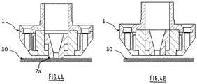
Figures 4A et 4B montrent la buse de l'invention avec l'élément mobile dans deux positions différentes.
- the
Figure 1A schematizes a focusing head of a conventional laser cutting plant, - the
Figure 1B schematizes the size of the laser spot relative to the size of the nozzle orifice, - the
Figure 2 is a sectional diagram of the body of a nozzle according to one embodiment of the invention, without a mobile element being arranged therein, - the
Figure 3 is a sectional diagram of a nozzle according to one embodiment of the invention, and - the
Figures 4A and 4B show the nozzle of the invention with the movable element in two different positions.
La
Le gaz d'assistance peut être un gaz actif, tel de l'oxygène, de l'air, du CO2, de l'hydrogène, ou un gaz inerte, tel l'argon, l'azote, l'hélium, ou un mélange de plusieurs ces gaz actifs et/ou inertes. La composition du gaz est choisie notamment en fonction de la nature de la pièce à couper.The assist gas may be an active gas, such as oxygen, air, CO 2 , hydrogen, or an inert gas, such as argon, nitrogen, helium, or a mixture of several such active and / or inert gases. The composition of the gas is chosen in particular according to the nature of the piece to be cut.
Le faisceau qui vient impacter la pièce va y fondre le métal qui sera expulsé en-dessous de la pièce par la pression du gaz d'assistance.The beam that impacts the part will melt the metal that will be expelled below the workpiece by the pressure of the assist gas.
La
Pour réduire considérablement la consommation de gaz ainsi que la pression nécessaire à la découpe, il a été proposé dans le document
Selon
Toutefois, la construction de cette buse laser n'est idéale, et ce pour les raisons déjà mentionnées.However, the construction of this laser nozzle is ideal for the reasons already mentioned.
Pour y remédier, et comme illustré sur les
En fait, lors de l'assemblage de la buse, l'élément mobile 2 est tout d'abord agencé au sein de la première partie 11. La deuxième partie 12 vient ensuite se superposer et se fixer à la première partie 11 du corps 1 de buse. Ainsi, il est possible de conserver une deuxième partie 12 dont la géométrie est adaptée à la tête de focalisation sur laquelle doit se fixer le corps 1 de buse, tout en augmentant le volume disponible au sein de la première partie 11 pour accueillir l'élément mobile 2.In fact, during assembly of the nozzle, the
Il est alors possible d'élargir le passage axial 5 et l'orifice de sortie 6 de l'élément mobile 2, le diamètre de l'orifice de sortie 6 pouvant aller typiquement jusqu'à 10 mm, de préférence 6 mm. Ceci permet d'élargir la couverture gazeuse de la saignée de coupe et de prévenir les phénomènes d'oxydation des faces de coupe pouvant se produire aux grandes vitesses de coupe atteintes sur fines épaisseurs de tôle, typiquement de 3 à 30 m/min pour des épaisseurs inférieures à 3 mm, en particulier lors de la découpe d'acier inoxydable sous azote en tant que gaz d'assistance 23.It is then possible to widen the axial passage 5 and the
En outre, la buse selon l'invention permet de préserver la tête de focalisation des effets néfastes provoqués par d'éventuels obstacles sur la tôle. En effet, lorsqu'un obstacle se trouve à la surface de la tôle, c'est essentiellement au niveau de la première partie 11 du corps 1 de buse, positionnée immédiatement au-dessus de la tôle que se produit le choc. La construction du corps 1 de buse en plusieurs parties assemblées, et non plus en un seul bloc, procure une certaine souplesse de déplacement de la première partie 11 par rapport à la deuxième partie 12 et/ou une possibilité de rupture de la liaison entre la première partie 11 et la deuxième partie 12. Ceci permet, en cas de choc, de minimiser les risques de déplacement de la deuxième partie 12 par rapport à la tête de focalisation et/ou de la tête de focalisation par rapport à son support.In addition, the nozzle according to the invention makes it possible to preserve the focusing head from the harmful effects caused by possible obstacles on the sheet. Indeed, when an obstacle is on the surface of the sheet, it is essentially at the
Avantageusement, le corps 1 de buse est une pièce de révolution traversée de part en part par un premier logement axial 3 d'axe AA qui s'étend depuis la face arrière 1b du corps 1 jusqu'à la face avant 1a dudit corps 1.Advantageously, the
Le premier logement axial 3 débouche au niveau des deux faces avant 1a et arrière 1b du corps 1 de buse. La face arrière 1b porte un orifice d'entrée 9, alors que la face avant 1a porte un premier orifice de sortie 4 du corps de buse 1, les premiers orifices d'entrée 9 et de sortie 4 étant coaxiaux d'axe AA.The first
Ce premier logement axial 3 est en fait un évidement formé d'une deuxième portion 3b s'étendant à travers la deuxième partie 12 et d'une première portion 3a s'étendant à travers la première partie 11. Les première et deuxième portions 3a, 3b dont de préférence de forme cylindrique, la première portion 3a comprenant un premier épaulement 19a interne se projetant radialement vers le centre du premier logement 3, ledit premier épaulement interne 19a étant formé par une restriction de la section du premier logement axial 3 au niveau du premier orifice de sortie 4. De préférence, le premier épaulement interne 19a est aménagé au niveau du fond dudit premier logement axial 3.This first
La buse comprend par ailleurs un élément mobile 2 venant s'insérer dans le premier logement 3 du corps 1 de buse, de préférence coaxialement au corps 1, comme visible enThe nozzle further comprises a
Le passage axial 5 peut avoir un profil interne conique, avec canal de sortie cylindrique ou non, tronconique, de type convergent/divergent (i.e. tuyère de Laval) ou toute autre géométrie adaptée.The axial passage 5 may have a conical internal profile, with a cylindrical or non-conical outlet channel, of the convergent / divergent type (i.e. Laval nozzle) or any other suitable geometry.
Dans le cadre de l'invention, l'élément mobile (2) est formé d'un matériau conducteur électriquement. En effet, l'élément mobile se situe à proximité immédiate de la zone de découpe et ce type de matériau offre une résistance plus grande aux fortes températures ainsi qu'aux chocs (impacts de l'élément mobile sur la tôle) et/ou thermiques (allumage et extinction du laser). Par exemple, l'élément mobile 2 peut être formé d'acier, d'acier trempé, de carbone, d'un matériau composite...In the context of the invention, the movable element (2) is formed of an electrically conductive material. Indeed, the movable element is located in the immediate vicinity of the cutting zone and this type of material offers greater resistance to high temperatures and shocks (impacts of the movable element on the sheet) and / or thermal (switching on and off the laser). For example, the
De préférence, on choisira un matériau conducteur induisant un frottement limité sur la tôle pour limiter une usure de la tôle, c'est-à-dire un matériau peu ou pas abrasif.Preferably, a conductive material will be chosen which induces a limited friction on the sheet to limit wear of the sheet, that is to say a material that is little or not abrasive.
Avantageusement, l'élément mobile 2 est formé d'un alliage de bronze au plomb. En effet, un tel matériau offre l'avantage de présenter de bonnes propriétés de frottement, une bonne résistance à l'usure sous fortes charges et une bonne tenue à la corrosion. Son utilisation est particulièrement avantageuse dans des conditions de lubrification difficiles du fait de son pouvoir auto-lubrifiant. Ceci réduit grandement, voire élimine, le risque de rayer ou d'entraîner la tôle lorsque l'élément mobile est en contact avec sa surface.Advantageously, the
A noter que dans le cadre de la présente invention, on entend par matériau électriquement isolant, ou matériau diélectrique, un matériau qui ne conduit pas l'électricité, c'est-à-dire qui interdit le passage de courant électrique entre deux éléments conducteurs électrique. A l'inverse, un matériau conducteur électriquement contient de nombreux porteurs de charge électrique pouvant se déplacer facilement sous l'action d'un champ électromagnétique.Note that in the context of the present invention, the term "electrically insulating material, or dielectric material, a material that does not conduct electricity, that is to say that prohibits the passage of electrical current between two conductive elements electric. Conversely, an electrically conductive material contains many electric charge carriers that can move easily under the action of an electromagnetic field.
Le corps (1) de buse est formé d'un matériau conducteur électriquement. En d'autres termes, les première et deuxième parties 11, 12 du corps 1 de buse sont formées d'un matériau conducteur électriquement. Ce matériau peut être un matériau métallique, par exemple de l'acier, du bronze, de l'acier réfractaire, du cuivre, du laiton, ou un matériau céramique électriquement conducteur.The nozzle body (1) is formed of an electrically conductive material. In other words, the first and
L'utilisation d'un matériau conducteur pour les première et deuxième parties 11, 12 du corps 1 de buse est avantageuse car elle permet l'utilisation d'un système de capteur capacitif. En effet, en condition d'utilisation, le corps 1 de buse est monté à l'extrémité d'une tête de focalisation 20 comprenant, de façon connue en soi, un système de capteur capacitif. Ce système utilise l'effet capacitif pour détecter de faibles variations de distance entre deux éléments conducteurs formant un condensateur. La distance séparant les deux éléments conducteurs est déterminée en mesurant la capacité électrique de ce condensateur, qui dépend notamment de la permittivité diélectrique du milieu qui les sépare.The use of a conductive material for the first and
Les buses laser traditionnelles sont en général formées d'un matériau électriquement conducteur tel le cuivre. Lorsque la buse est montée à l'extrémité de la tête, elle est reliée électriquement au système de capteur capacitif. De la sorte, le capteur capacitif peut mesurer la capacité électrique entre la tôle et la surface plane de la buse située en regard de la tôle. Le capteur capacitif est lui-même relié électriquement aux commandes de déplacements de la tête de focalisation 20 de manière à ajuster le positionnement en hauteur de la tête en cas de variations de la capacité mesurée.Traditional laser nozzles are generally formed of an electrically conductive material such as copper. When the nozzle is mounted at the end of the head, it is electrically connected to the capacitive sensor system. In this way, the capacitive sensor can measure the electrical capacitance between the sheet and the flat surface of the nozzle located opposite the sheet. The capacitive sensor is itself electrically connected to the movement commands of the focusing
Lorsque la buse laser selon l'invention est assemblée à la tête de focalisation, le corps 1 de buse en matériau conducteur peut ainsi être relié électriquement au système de capteur capacitif équipant la tête. Avantageusement, cette liaison électrique s'effectue par contact d'au moins une portion de la deuxième partie 12 du corps 1 avec une pièce de la tête 20 formée d'un matériau électriquement conducteur et faisant partie du système de capteur capacitif.When the laser nozzle according to the invention is assembled to the focusing head, the
Lorsque l'élément mobile 2 électriquement conducteur se met en contact avec la tôle, il est au même potentiel électrique que celle-ci.When the
Par conséquent, la buse selon l'invention comprend un manchon séparateur 14 agencé entre la première partie 11 et l'élément mobile 2 et formé d'un matériau conducteur électriquement.Therefore, the nozzle according to the invention comprises a
Ceci permet de ne pas mettre en défaut le capteur capacitif ni de perturber son fonctionnement.This makes it possible not to fault the capacitive sensor or to disrupt its operation.
En fait, le capteur capacitif mesure alors une ou plusieurs valeurs de capacité électrique entre la face avant 1a du corps 1 de buse et la surface supérieure de la pièce à couper 30. A partir de ces valeurs, le capteur permet d'ajuster la distance entre la coiffe et la tôle à une valeur constante ou quasi-constante, typiquement entre 0,1 et 5 mm, de préférence entre 0,5 et 2 mm, et de corriger les défauts de planéité de la tôle.In fact, the capacitive sensor then measures one or more capacitance values between the
Dans le cadre de la présente invention, on utilise un manchon séparateur 14 formé d'un matériau présentant une faible permittivité.In the context of the present invention, a
En effet, dans le cas d'une buse laser classique, i. e. sans élément mobile, la mesure de capacité a lieu entre deux surfaces planes en regard l'une de l'autre, i. e. la face avant du corps de buse et la surface supérieure de la pièce à couper. Dans ce cas, la capacité C s'exprime (en pF/m) selon la formule suivante : ![]()
![]()
Dans le cas d'une buse laser à élément mobile selon l'invention, le système de capteur capacitif réalise en fait deux types de mesures de capacité. Avant que l'élément mobile ne se mette en contact avec la surface supérieure de la tôle, le capteur réalise une première mesure entre deux surfaces planes, i. e. la face avant du corps de buse et la surface supérieure de la pièce à couper. Cette mesure est la mesure de référence permettant de maintenir le corps 1 de buse à la hauteur souhaitée par rapport à la pièce à couper. Une fois que l'élément mobile 2 est en contact avec la pièce pour réaliser l'opération de coupage proprement dite, celui-ci se met au même potentiel que la pièce. Le capteur réalise alors, en plus de la première mesure de capacité, une mesure de capacité globale résultant d'une multitude de mesures prises entre la surface extérieure de l'élément mobile 2 et la surface intérieure de la première partie 11 du corps. En effet, la distance entre ces surfaces varie selon la position considérée le long de l'axe AA de la buse.In the case of a moving element laser nozzle according to the invention, the capacitive sensor system actually performs two types of capacitance measurements. Before the movable element comes into contact with the upper surface of the sheet, the sensor makes a first measurement between two flat surfaces, ie the front face of the nozzle body and the upper surface of the workpiece. This measurement is the reference measurement for maintaining the
En un point donné le long de l'axe AA de la buse, la capacité C s'exprime (en pF/m) selon la formule suivante : 
Or, l'inventeur de la présente invention a mis en évidence que l'utilisation d'un manchon séparateur 14 formé d'un matériau de faible permittivité relative permettait d'améliorer la stabilité du capteur capacitif en réduisant les perturbations dues à la mesure de capacité globale, en plus de la première mesure de référence. Il est ainsi possible de conserver en cours de coupe un positionnement du corps 1 de buse à une hauteur très proche, voire identique à la hauteur de référence avant le début de la coupe.However, the inventor of the present invention has demonstrated that the use of a
Par matériau à faible permittivité relative, on entend un matériau dont la permittivité relative est inférieure à 8, de préférence inférieure à 6.Relative low permittivity material means a material whose relative permittivity is less than 8, preferably less than 6.
Avantageusement, l'épaisseur en tout point de la paroi périphérique du manchon séparateur 14 est d'au moins 0,5 mm, de préférence au moins 1 mm, et avantageusement comprise entre 0,5 et 10 mm, de préférence comprise entre 1 et 3 mm.Advantageously, the thickness at any point of the peripheral wall of the
On choisira aussi avantageusement un matériau résistant à des températures de l'ordre de 100 à 2000 °C, typiquement entre 500 et 1500 °C.It is also advantageous to choose a material resistant to temperatures of the order of 100 to 2000 ° C, typically between 500 and 1500 ° C.
Selon un mode de réalisation particulier, les dimensions extérieures du manchon séparateur 14 sont choisies de sorte à ménager un espace entre la première partie 11 du corps 1 de buse et l'élément mobile 2. Cet espace rempli d'air permet de réduire encore plus l'influence néfaste de la mesure de capacité globale sur la stabilité du positionnement en hauteur du corps 1 de buse.According to a particular embodiment, the outer dimensions of the
De préférence, le manchon séparateur 14 est formé d'un matériau choisi parmi : les mousses de céramique telles la mousse d'alumine ou l'alumine poreuse, les vitrocéramiques, par exemple le Macor®, ou les céramiques techniques telles le nitrure de bore, la mullite, la stéatite, la cordiérite. Le tableau 1 ci-dessous présente les plages de valeurs de permittivité relative des matériaux précités, celles-ci pouvant varier selon les grades de matériaux sélectionnés et les types de procédés de fabrication utilisés.Preferably, the
L'utilisation d'un matériau céramique, tel le nitrure de bore, est particulièrement avantageuse du fait de sa bonne résistance aux fortes température ainsi qu'aux chocs thermiques et à l'usure. Le nitrure de bore en particulier offre une excellente usinabilité.
Avantageusement, le manchon séparateur 14 comprend un deuxième logement axial 15 comprenant un troisième orifice de sortie 16 situé au niveau d'une face avant 14a dudit manchon séparateur 14, l'élément mobile 2 étant agencé dans ledit deuxième logement axial 15 et ledit troisième orifice de sortie 16 débouchant au-dessus dudit deuxième orifice de sortie 6 du passage axial 5 de l'élément mobile 2 lorsque la partie avant 2a fait saillie à l'extérieur du premier logement axial 3. Le deuxième logement axial 15 comprend avantageusement un deuxième épaulement interne 19b se projetant radialement vers le centre dudit deuxième logement 15 et situé de préférence au fond dudit deuxième logement 15.Advantageously, the
La paroi périphérique de l'élément mobile 2 comprend avantageusement une première butée 18 agencée au niveau de la surface externe. De préférence, la première butée 10 est de forme annulaire et s'étend sur tout ou partie de la périphérie de l'élément mobile 2. Selon que la buse comprenne ou non un manchon intermédiaire 14, la première butée 18 est agencée en regard du premier épaulement 19a du corps 1 de buse ou du deuxième épaulement 19b du manchon 14.The peripheral wall of the
Comme schématisé sur les
Les premiers moyens de fixation 7, 8 peuvent permettre une fixation amovible ou inamovible de la première 11 à la deuxième partie 12 du corps 1 de buse.The first fastening means 7, 8 may allow a removable or irremovable attachment of the first 11 to the
Selon un mode de réalisation préféré de l'invention, les premiers moyens de fixation 7, 8 comprennent au moins un premier perçage taraudé traversant au moins partiellement les première et deuxième parties 11, 12 du corps 1 de buse et une pièce cylindrique filetée (non illustrée) conformée pour être vissée dans ledit premier perçage taraudé. Les
Selon une variante de réalisation, les premiers moyens de fixation 7,8 comprennent des moyens de fixation de la première partie 11 à la deuxième partie 12 par clipsage, baïonnette ou sertissage.According to an alternative embodiment, the first fastening means 7,8 comprise means for fixing the
De préférence, la deuxième partie 12 du corps 1 de buse comprend des deuxièmes moyens de fixation 10 aptes à et conçus pour fixer ladite deuxième partie 12 à la tête de focalisation laser 20.Preferably, the
Comme illustré sur la
Avantageusement, les premiers 7, 8 et deuxièmes moyens de fixation 10 sont aptes à et conçus pour fixer la deuxième partie 12 du corps 1 de buse à la tête de focalisation laser 20 plus solidement qu'à la première partie 11, de manière à ce que, en cas de choc au niveau de la première partie 11 du corps 1 de buse, il se produise une déformation ou une rupture du corps 1 de buse essentiellement entre la première partie 11 et la deuxième partie 12 du corps 1 de buse. De la sorte, on minimise grandement le risque de rupture ou de déformation au niveau de la tête de focalisation 20, ce qui évite de longues opérations de maintenance au niveau de l'installation de découpe.Advantageously, the first 7, 8 and second fastening means 10 are adapted to and designed to fix the
Selon un mode de réalisation particulier, ce contrôle de la solidité de la fixation de la deuxième partie 12 à la tête de focalisation 20 par rapport à la solidité de la fixation de la deuxième partie 12 à la première partie 11 peut être obtenu par un dimensionnement des filets, en termes de diamètres et/ou de pas, des filetages ou taraudages des premiers 7, 8 et deuxièmes moyens de fixation 10. Les premiers 7, 8 et deuxièmes moyens de fixation 10 peuvent aussi être des moyens de fixation rapide, en particulier des moyens de fixation à encliquetage ou clipsage, sertissage ou à baïonnette.According to a particular embodiment, this control of the strength of the fastening of the
Pendant l'utilisation de la buse, le faisceau laser 22 et le gaz d'assistance 23 traversent le passage axial 5 de l'élément mobile 2 et ressortent par le deuxième orifice de sortie 6 débouchant au niveau de la partie avant 2a formant jupe.During the use of the nozzle, the
Avantageusement, l'élément mobile 2 est déplaçable en translation selon l'axe AA dans le premier logement axial 3 en direction du premier orifice de sortie 4 jusqu'à ce que la partie avant 2a fasse saillie à l'extérieur dudit premier logement axial 3, au travers du premier orifice de sortie 4.Advantageously, the
De préférence, l'élément mobile 2 se déplace sous l'effet de la pression du gaz d'assistance 23 qui vient s'exercer sur ledit élément mobile 2, ce qui tend à le pousser en direction de la pièce à couper 30.Preferably, the
Le déplacement en translation selon l'axe AA de l'élément mobile 2 va provoquer le rapprochement de la jupe de la surface supérieure 30 de la tôle à couper, qui vont venir en contact l'une de l'autre, comme illustré en
Avantageusement, un élément élastique 17, tel un ressort, est agencé dans le premier logement axial 3, entre le corps de buse 1 et l'élément mobile 2 ou dans le deuxième logement axial 15, entre le manchon séparateur 14 et l'élément mobile 2. Plus précisément, l'élément élastique de manière à exercer une force de rappel élastique sur l'élément mobile 2 dans un sens tendant à l'éloigner de la pièce à couper 30. Ainsi, en fin de coupe, lorsque le gaz est coupé et que la pression gazeuse cesse de s'exercer sur l'élément mobile 2, celui-ci peut être rappelé dans sa position de repos et donc la jupe rentrer à l'intérieur du premier logement 3. L'élément élastique 17 est avantageusement agencé entre la première butée 18 et le premier épaulement 19a du corps 1 de buse ou du deuxième épaulement 19b du manchon 14 selon qu'un manchon est agencé ou non dans le premier logement axial 3.Advantageously, an elastic element 17, such as a spring, is arranged in the first
L'élément élastique 17 permet ainsi de limiter le phénomène d'usure de la jupe lors des phases de perçage de la tôle qui précèdent généralement les phases de découpe. En effet le perçage est le plus souvent opéré avec de faibles pressions de gaz, typiquement moins de 4 bar. L'élément élastique exerce alors une force de rappel suffisante pour que la jupe remonte totalement ou quasi-totalement dans le premier logement 3 et soit ainsi protégée des projections de métal fondu générées par le perçage.The elastic element 17 thus makes it possible to limit the phenomenon of wear of the skirt during the drilling phases of the sheet which generally precede the cutting phases. Indeed the drilling is most often operated with low gas pressures, typically less than 4 bar. The elastic element then exerts a sufficient restoring force so that the skirt rises completely or almost completely in the
En outre, l'élément élastique 17 facilite les déplacements rapides de la tête de découpe à faible distance au-dessus de la tôle, sans gaz de coupe ni faisceau, puisque la pression gazeuse cesse alors de s'exercer sur l'élément mobile et la jupe rentre à l'intérieur du premier logement 3. Seule la jupe remonte et il n'est pas nécessaire de relever la tête de focalisation supportant la buse.In addition, the elastic element 17 facilitates rapid movements of the cutting head a short distance above the sheet, without cutting gas or beam, since the gas pressure then ceases to be exerted on the movable member and the skirt returns inside the
L'élément élastique 1 permet aussi de limiter la pression exercée par l'élément mobile 2 sur la pièce à couper lorsque celui-ci se déplace en direction de la pièce sous l'effet du gaz de coupe. Plus précisément, la force de rappel de l'élément élastique 8 est avantageusement dimensionnée de manière à maintenir l'élément mobile 2 au contact de la pièce à couper tout en limitant la pression que ledit élément exerce sur la tôle, pour minimiser grandement, voire éliminer, tout risque de déformation de la tôle dans laquelle la pièce est découpée, de rayures de la surface de la tôle, et d'entraînement de la tôle.The
Selon le cas, l'élément mobile 2 peut comprendre une partie avant 2a de forme cylindrique, c'est-à-dire de diamètre externe constant le long de l'axe AA, ou une portion d'extrémité conformée pour passer sur un dénivelé ou un obstacle sans ou avec un choc grandement réduit au niveau de la jupe 6.Depending on the case, the
Avantageusement, la partie avant 2a comprend une portion d'extrémité dont le diamètre externe diminue progressivement en direction du deuxième orifice de sortie 12. De la sorte, la partie avant 2a est conformée pour faciliter son passage sur des reliefs ou obstacles présents à la surface de la tôle. Les chocs sont mieux absorbés car la diminution progressive du diamètre externe de la portion d'extrémité favorise la remontée de la jupe 6 vers le logement 5 lorsque la jupe 6 rencontre un dénivelé ou sur un obstacle ponctuel.Advantageously, the
Par portion d'extrémité, on entend une portion de la partie avant 2a située à l'extrémité de ladite partie avant, c'est-à-dire en regard de la surface supérieure de la tôle à couper.By end portion is meant a portion of the
Optionnellement, au moins un élément d'étanchéité, par exemple un joint élastomère, est agencé entre le corps de buse 1 et l'élément mobile 2 ou entre le manchon séparateur 14 et l'élément mobile 2, en particulier un ou plusieurs joints toriques, ce qui permet d'assurer une étanchéité entre le corps de buse 1 ou le manchon séparateur 14 et l'insert mobile 2. De préférence, ledit élément d'étanchéité est agencé dans une gorge périphérique aménagée dans la paroi périphérique externe de l'élément mobile 2.Optionally, at least one sealing element, for example an elastomeric seal, is arranged between the
En fait, l'élément mobile 2 de la buse selon l'invention est apte à se déplacer entre plusieurs positions comprenant au moins :
- une position de travail dans laquelle la partie avant 2a fait totalement ou quasi-totalement saillie à l'extérieur du premier logement axial 3 du corps de buse 1, au travers du premier orifice de sortie 4, et vient au contact de la pièce 30 à couper, comme illustré en
Figure 4A , et - une position de repos dans laquelle la partie avant 2a est totalement ou quasi-totalement rentrée dans le premier logement axial 3 du corps de buse 1, comme illustré en
Figure 4B .
- a working position in which the
front portion 2a is wholly or almost completely protruded outside the firstaxial housing 3 of thenozzle body 1, through the first outlet orifice 4, and comes into contact with thepiece 30 to cut, as illustrated inFigure 4A , and - a rest position in which the
front portion 2a is totally or almost completely retracted into the firstaxial housing 3 of thenozzle body 1, as illustrated in FIG.Figure 4B .
Bien entendu, l'élément mobile 2 peut occuper des positions intermédiaires dans lesquelles la partie avant 2a ne fait que partiellement saillie à l'extérieur du premier logement axial 3 du corps de buse 1. Ces positions intermédiaires peuvent être notamment fonction de la pression exercée par le gaz sur l'élément mobile 2.Of course, the
Afin de montrer l'efficacité de la buse selon l'invention par rapport à une buse standard, c'est-à-dire une buse classique sans élément mobile, et donc l'intérêt de forcer le gaz dans la saignée de coupe grâce à la mise en oeuvre d'une jupe montée sur un élément mobile, on a réalisé des essais comparatifs en utilisant une installation de coupage avec générateur laser CO2 pour générer un faisceau laser qui est amené à une tête de focalisation laser comprenant des optiques de focalisation, à savoir des lentilles.In order to show the effectiveness of the nozzle according to the invention with respect to a standard nozzle, that is to say a conventional nozzle without moving element, and therefore the interest of forcing the gas into the cutting bleed thanks to the implementation of a skirt mounted on a movable element, comparative tests were carried out using a cutting unit with CO 2 laser generator to generate a laser beam which is fed to a laser focusing head comprising focusing optics , namely lenses.
La tête de focalisation laser est équipée, selon le cas :
- d'une buse standard avec orifice de sortie de 1,8 mm de diamètre, ou
- d'une buse selon la
Figure 3 avec corps en deux parties, jupe mobile cylindrique en acier et passage axial de la jupe de profil conique avec canal de sortie cylindrique d'un diamètre de 1,8 mm de diamètre.
- a standard nozzle with a 1.8 mm diameter outlet, or
- a nozzle according to the
Figure 3 with two-part body, cylindrical steel skirt and axial passage of the conical profile skirt with cylindrical outlet channel with a diameter of 1.8 mm in diameter.
Au cours de cet essai, le capteur capacitif est paramétré pour ajuster la distance entre la face avant de la coiffe et la surface supérieure de la tôle à couper à une distance de 1 mm.During this test, the capacitive sensor is set to adjust the distance between the front face of the cap and the upper surface of the sheet to be cut at a distance of 1 mm.
Le gaz d'assistance utilisé est de l'azote.The assist gas used is nitrogen.
La tôle à couper est en acier inoxydable 304 L de 5 mm d'épaisseur.The cutting sheet is made of 304 L stainless steel 5 mm thick.
Le faisceau laser à une puissance de 4 kW et la vitesse de coupe est de 2,6 m/min.The laser beam has a power of 4 kW and the cutting speed is 2.6 m / min.
Les résultats obtenus ont montré que :
- avec la buse standard, une pression du gaz de 14 bar est insuffisante pour obtenir une coupe de qualité. En effet, à 14 bar, les bords de coupe comportent de nombreuses bavures adhérentes. Ceci démontre que l'évacuation du métal en fusion se fait mal du fait d'une action insuffisante du gaz sur le métal en fusion devant être expulsé. Afin d'éliminer ces bavures, une pression de 16 bar a été nécessaire.
- avec la buse de l'invention, des essais faits à des pressions s'échelonnant entre 1 et 5 bar ont conduit à des coupes de bonne qualité, c'est-à-dire à des bords de coupe dépourvus de bavures adhérentes. La jupe de la buse permet de canaliser le gaz dans la saignée et d'expulser efficacement le métal fondu.
- with the standard nozzle, a gas pressure of 14 bar is insufficient to obtain a quality cut. Indeed, at 14 bar, the cutting edges have many adherent burrs. This demonstrates that the evacuation of the molten metal is hurt due to insufficient action of the gas on the molten metal to be expelled. In order to eliminate these burrs, a pressure of 16 bar was necessary.
- with the nozzle of the invention, tests made at pressures ranging between 1 and 5 bar led to good quality cuts, that is to say to cutting edges devoid of adherent burrs. The skirt of the nozzle allows to channel the gas in the kerf and effectively expel the molten metal.
La tête de focalisation laser est équipée, selon le cas :
- d'une buse standard (A) avec orifice de sortie de 1.5 mm de diamètre,
- d'une buse avec corps monobloc (B) selon le document
WO-A-2012/156608 - d'une buse (C) selon la
Figure 3 avec corps en deux parties, jupe mobile cylindrique en acier et passage axial de la jupe de profil conique avec canal de sortie cylindrique d'un diamètre de 6 mm de diamètre.
- a standard nozzle (A) with 1.5 mm diameter outlet,
- of a nozzle with one-piece body (B) according to the document
WO-2012/156608 - a nozzle (C) according to the
Figure 3 with two-part body, cylindrical steel skirt and axial passage of the conical profile skirt with cylindrical outlet channel with a diameter of 6 mm.
Au cours de cet essai, le capteur capacitif est paramétré pour ajuster la distance entre la face avant de la coiffe et la surface supérieure de la tôle à couper à une distance de 1 mm.During this test, the capacitive sensor is set to adjust the distance between the front face of the cap and the upper surface of the sheet to be cut at a distance of 1 mm.
Le gaz d'assistance utilisé est de l'azote.The assist gas used is nitrogen.
La tôle à couper est en acier inoxydable 304 L de 2 mm d'épaisseur.The cutting sheet is made of 304 L stainless steel of 2 mm thickness.
Le faisceau laser à une puissance de 4 kW.The laser beam has a power of 4 kW.
Le Tableau ci-dessous présente les résultats de coupe obtenus dans les conditions de l'Exemple 2 avec les trois types de buse A, B, C susmentionnés, en termes de vitesse de coupe, de pression de gaz d'assistance mise en oeuvre et de présence ou non de bavures et/ou de traces d'oxydation sur les faces de coupe.The table below shows the cutting results obtained under the conditions of Example 2 with the three types of nozzle A, B, C mentioned above, in terms of cutting speed, pressure of assistance gas used and presence or absence of burrs and / or traces of oxidation on the cutting faces.
Ces essais démontrent clairement l'efficacité de la buse C selon l'invention qui permet de réduire considérablement les pressions de gaz à mettre en oeuvre par rapport à une buse standard, toutes conditions étant égales par ailleurs, et donc de réduire également les consommations gazeuses. En outre, la buse C selon l'invention permet un élargissement du diamètre de l'orifice de sortie du gaz d'assistance, ce qui permet sur fine épaisseur d'augmenter la vitesse de coupe sans générer de phénomène d'oxydation des faces de coupe, ce qui n'était pas possible avec la buse à jupe mobile B selon l'art antérieur.
Claims (18)
Applications Claiming Priority (3)
| Application Number | Priority Date | Filing Date | Title |
|---|---|---|---|
| FR1454093A FR3020774B1 (en) | 2014-05-06 | 2014-05-06 | LASER NOZZLE WITH INTERNAL MOBILE ELEMENT AND DEFORMABLE BODY |
| PCT/FR2015/051090 WO2015170029A1 (en) | 2014-05-06 | 2015-04-22 | Nozzle for laser cutting with an internal moveable element and a sleeve with low relative permittivity |
| EP15725779.1A EP3140075B1 (en) | 2014-05-06 | 2015-04-22 | Nozzle for laser cutting with an internal moveable element and a sleeve with low relative permittivity |
Related Parent Applications (2)
| Application Number | Title | Priority Date | Filing Date |
|---|---|---|---|
| EP15725779.1A Division-Into EP3140075B1 (en) | 2014-05-06 | 2015-04-22 | Nozzle for laser cutting with an internal moveable element and a sleeve with low relative permittivity |
| EP15725779.1A Division EP3140075B1 (en) | 2014-05-06 | 2015-04-22 | Nozzle for laser cutting with an internal moveable element and a sleeve with low relative permittivity |
Publications (2)
| Publication Number | Publication Date |
|---|---|
| EP3315246A1 true EP3315246A1 (en) | 2018-05-02 |
| EP3315246B1 EP3315246B1 (en) | 2020-10-21 |
Family
ID=50976956
Family Applications (3)
| Application Number | Title | Priority Date | Filing Date |
|---|---|---|---|
| EP17198493.3A Active EP3315246B1 (en) | 2014-05-06 | 2015-04-22 | Laser nozzle with internal mobile element and nozzle body being made in two parts connected through fixtures |
| EP17198494.1A Active EP3315247B1 (en) | 2014-05-06 | 2015-04-22 | Nozzle for laser cutting with internal mobile element and sleeve having low relative permittivity ; process of cutting with a laser beam of a metallic workpiece using such a nozzle |
| EP15725779.1A Active EP3140075B1 (en) | 2014-05-06 | 2015-04-22 | Nozzle for laser cutting with an internal moveable element and a sleeve with low relative permittivity |
Family Applications After (2)
| Application Number | Title | Priority Date | Filing Date |
|---|---|---|---|
| EP17198494.1A Active EP3315247B1 (en) | 2014-05-06 | 2015-04-22 | Nozzle for laser cutting with internal mobile element and sleeve having low relative permittivity ; process of cutting with a laser beam of a metallic workpiece using such a nozzle |
| EP15725779.1A Active EP3140075B1 (en) | 2014-05-06 | 2015-04-22 | Nozzle for laser cutting with an internal moveable element and a sleeve with low relative permittivity |
Country Status (7)
| Country | Link |
|---|---|
| US (1) | US20170189993A1 (en) |
| EP (3) | EP3315246B1 (en) |
| JP (1) | JP6594900B2 (en) |
| CN (1) | CN106457484B (en) |
| ES (2) | ES2678396T3 (en) |
| FR (1) | FR3020774B1 (en) |
| WO (1) | WO2015170029A1 (en) |
Families Citing this family (11)
| Publication number | Priority date | Publication date | Assignee | Title |
|---|---|---|---|---|
| DE102015208157B4 (en) | 2015-05-04 | 2017-06-14 | Trumpf Werkzeugmaschinen Gmbh + Co. Kg | Cutting gas nozzle and laser cutting method with sliding valve sleeve for adjusting the flow characteristics |
| JP2018533481A (en) * | 2015-10-30 | 2018-11-15 | ハイパーサーム インコーポレイテッド | Double nozzle for laser processing head |
| US10569360B2 (en) | 2015-10-30 | 2020-02-25 | Hypertherm, Inc. | Highly positioned laser processing nozzle |
| US11850681B2 (en) | 2015-10-30 | 2023-12-26 | Hypertherm, Inc. | Highly positioned laser processing nozzle |
| DE102016215019C5 (en) * | 2016-08-11 | 2023-04-06 | Trumpf Werkzeugmaschinen Gmbh + Co. Kg | Process for laser cutting with optimized gas dynamics |
| DE102017205084A1 (en) * | 2017-03-27 | 2018-09-27 | Trumpf Werkzeugmaschinen Gmbh + Co. Kg | Gas nozzle with wear-resistant sleeve for encapsulation of a cutting gas jet |
| TWI634963B (en) * | 2017-11-16 | 2018-09-11 | 方菘嶺 | Laser processing machine and its nozzle |
| JP6793214B2 (en) * | 2019-02-15 | 2020-12-02 | 株式会社アマダ | Laser processing nozzle and laser processing equipment |
| US11654514B2 (en) * | 2019-11-15 | 2023-05-23 | Kobayashi Manufacture Co., Ltd | Laser welding system |
| CN115338548B (en) * | 2022-10-14 | 2023-05-26 | 四川智龙激光科技有限公司 | Obstacle avoidance method and system for cutting head of plane cutting machine tool |
| CN117182352B (en) * | 2023-11-06 | 2024-02-20 | 武汉锐科光纤激光技术股份有限公司 | Laser cutting head |
Citations (11)
| Publication number | Priority date | Publication date | Assignee | Title |
|---|---|---|---|---|
| US4031351A (en) | 1972-10-25 | 1977-06-21 | Groupement Atomique Alsacienne Atlantique | High energy laser beam cutting method and apparatus |
| JPS6137393A (en) | 1984-07-30 | 1986-02-22 | Mitsubishi Electric Corp | Laser working machine |
| JPS626790A (en) | 1985-07-02 | 1987-01-13 | Mitsubishi Electric Corp | Laser beam machining head |
| JPS6340695A (en) | 1986-08-05 | 1988-02-22 | Mitsubishi Electric Corp | Nozzle for laser beam machine |
| JPS63108992A (en) | 1986-10-23 | 1988-05-13 | Mitsubishi Electric Corp | Laser beam machining head |
| US4782496A (en) * | 1987-11-05 | 1988-11-01 | United Technologies Corporation | Breakaway nozzle for a laser processing machine |
| EP1669159A1 (en) | 2004-12-07 | 2006-06-14 | Bystronic Laser AG | Processing nozzle for laser cutting with a nozzle sleeve projection over the work nozzle ; Laser processing device and process with such a work nozzle |
| JP2011177727A (en) | 2010-02-26 | 2011-09-15 | Amada Co Ltd | Laser beam machine |
| WO2012156608A1 (en) | 2011-05-16 | 2012-11-22 | L'air Liquide,Societe Anonyme Pour L'etude Et L'exploitation Des Procedes Georges Claude | Laser nozzle with mobile element |
| US20130015168A1 (en) * | 2010-03-29 | 2013-01-17 | Nissan Tanaka Corporation | Laser cutting method, laser cutting nozzle, and laser cutting device |
| FR2982184A1 (en) * | 2011-11-07 | 2013-05-10 | Air Liquide | LASER NOZZLE WITH MOBILE ELEMENT ON GAS LAYER |
Family Cites Families (7)
| Publication number | Priority date | Publication date | Assignee | Title |
|---|---|---|---|---|
| JPS626990U (en) * | 1985-06-26 | 1987-01-16 | ||
| DE29621281U1 (en) * | 1996-11-26 | 1997-01-23 | Girrbach Dental Gmbh | Shielding gas supply device |
| JPH11277271A (en) * | 1998-03-25 | 1999-10-12 | Amada Co Ltd | Laser beam machining method for surface coating material and laser beam machining head used for the method |
| US6822187B1 (en) * | 1998-09-09 | 2004-11-23 | Gsi Lumonics Corporation | Robotically operated laser head |
| KR100499657B1 (en) * | 2000-08-31 | 2005-07-07 | 미쓰비시덴키 가부시키가이샤 | Laser machining head |
| EP1500459B1 (en) * | 2003-07-22 | 2008-07-16 | Trumpf Werkzeugmaschinen GmbH + Co. KG | Nozzle for laser cutting machine |
| FR2997881B1 (en) * | 2012-11-09 | 2015-04-17 | Air Liquide | LASER NOZZLE WITH EXTERNAL MOBILE ELEMENT |
-
2014
- 2014-05-06 FR FR1454093A patent/FR3020774B1/en active Active
-
2015
- 2015-04-22 EP EP17198493.3A patent/EP3315246B1/en active Active
- 2015-04-22 ES ES15725779.1T patent/ES2678396T3/en active Active
- 2015-04-22 CN CN201580033435.9A patent/CN106457484B/en active Active
- 2015-04-22 US US15/308,666 patent/US20170189993A1/en not_active Abandoned
- 2015-04-22 ES ES17198494T patent/ES2764711T3/en active Active
- 2015-04-22 WO PCT/FR2015/051090 patent/WO2015170029A1/en active Application Filing
- 2015-04-22 EP EP17198494.1A patent/EP3315247B1/en active Active
- 2015-04-22 JP JP2016566739A patent/JP6594900B2/en active Active
- 2015-04-22 EP EP15725779.1A patent/EP3140075B1/en active Active
Patent Citations (11)
| Publication number | Priority date | Publication date | Assignee | Title |
|---|---|---|---|---|
| US4031351A (en) | 1972-10-25 | 1977-06-21 | Groupement Atomique Alsacienne Atlantique | High energy laser beam cutting method and apparatus |
| JPS6137393A (en) | 1984-07-30 | 1986-02-22 | Mitsubishi Electric Corp | Laser working machine |
| JPS626790A (en) | 1985-07-02 | 1987-01-13 | Mitsubishi Electric Corp | Laser beam machining head |
| JPS6340695A (en) | 1986-08-05 | 1988-02-22 | Mitsubishi Electric Corp | Nozzle for laser beam machine |
| JPS63108992A (en) | 1986-10-23 | 1988-05-13 | Mitsubishi Electric Corp | Laser beam machining head |
| US4782496A (en) * | 1987-11-05 | 1988-11-01 | United Technologies Corporation | Breakaway nozzle for a laser processing machine |
| EP1669159A1 (en) | 2004-12-07 | 2006-06-14 | Bystronic Laser AG | Processing nozzle for laser cutting with a nozzle sleeve projection over the work nozzle ; Laser processing device and process with such a work nozzle |
| JP2011177727A (en) | 2010-02-26 | 2011-09-15 | Amada Co Ltd | Laser beam machine |
| US20130015168A1 (en) * | 2010-03-29 | 2013-01-17 | Nissan Tanaka Corporation | Laser cutting method, laser cutting nozzle, and laser cutting device |
| WO2012156608A1 (en) | 2011-05-16 | 2012-11-22 | L'air Liquide,Societe Anonyme Pour L'etude Et L'exploitation Des Procedes Georges Claude | Laser nozzle with mobile element |
| FR2982184A1 (en) * | 2011-11-07 | 2013-05-10 | Air Liquide | LASER NOZZLE WITH MOBILE ELEMENT ON GAS LAYER |
Also Published As
| Publication number | Publication date |
|---|---|
| EP3140075B1 (en) | 2018-06-06 |
| ES2678396T3 (en) | 2018-08-10 |
| EP3315247A1 (en) | 2018-05-02 |
| ES2764711T3 (en) | 2020-06-04 |
| CN106457484B (en) | 2019-11-15 |
| FR3020774B1 (en) | 2016-05-13 |
| EP3315247B1 (en) | 2019-12-04 |
| EP3140075A1 (en) | 2017-03-15 |
| FR3020774A1 (en) | 2015-11-13 |
| CN106457484A (en) | 2017-02-22 |
| JP6594900B2 (en) | 2019-10-23 |
| WO2015170029A1 (en) | 2015-11-12 |
| US20170189993A1 (en) | 2017-07-06 |
| EP3315246B1 (en) | 2020-10-21 |
| JP2017514700A (en) | 2017-06-08 |
Similar Documents
| Publication | Publication Date | Title |
|---|---|---|
| EP3140075B1 (en) | Nozzle for laser cutting with an internal moveable element and a sleeve with low relative permittivity | |
| EP2916992B1 (en) | Laser nozzle having an internal mobile element and an external cover ; focusing head with such nozzle, system with such head ; process of laser cutting with one of these devices | |
| EP2709793B1 (en) | Laser nozzle having a movable piece | |
| EP2916990B1 (en) | Laser nozzle having an external mobile element | |
| CA2868207C (en) | Laser nozzle with mobile element of improved external profile | |
| EP2776206B1 (en) | Laser nozzle with an element mobile on a gas layer | |
| EP2916991B1 (en) | Laser nozzle having a modular mobile element made of electrically insulating material and an insert made of electrically conductive material | |
| EP3397394A1 (en) | Apparatus for additive manufacturing using powder spraying and melting | |
| FR2910224A1 (en) | PLASMA CUTTING TORCH WITH ADAPTIVE PLUNGER TUBE COOLING CIRCUIT | |
| FR2853269A1 (en) | Hybrid electric arc-laser beam welding of one or more metal components using a protective gas nozzle feeding gas at a different angle to the laser beam for improved delivery at the weld zone |
Legal Events
| Date | Code | Title | Description |
|---|---|---|---|
| PUAI | Public reference made under article 153(3) epc to a published international application that has entered the european phase |
Free format text: ORIGINAL CODE: 0009012 |
|
| STAA | Information on the status of an ep patent application or granted ep patent |
Free format text: STATUS: THE APPLICATION HAS BEEN PUBLISHED |
|
| AC | Divisional application: reference to earlier application |
Ref document number: 3140075 Country of ref document: EP Kind code of ref document: P |
|
| AK | Designated contracting states |
Kind code of ref document: A1 Designated state(s): AL AT BE BG CH CY CZ DE DK EE ES FI FR GB GR HR HU IE IS IT LI LT LU LV MC MK MT NL NO PL PT RO RS SE SI SK SM TR |
|
| RBV | Designated contracting states (corrected) |
Designated state(s): AL AT BE BG CH CY CZ DE DK EE ES FI FR GB GR HR HU IE IS IT LI LT LU LV MC MK MT NL NO PL PT RO RS SE SI SK SM TR |
|
| STAA | Information on the status of an ep patent application or granted ep patent |
Free format text: STATUS: REQUEST FOR EXAMINATION WAS MADE |
|
| 17P | Request for examination filed |
Effective date: 20181107 |
|
| STAA | Information on the status of an ep patent application or granted ep patent |
Free format text: STATUS: EXAMINATION IS IN PROGRESS |
|
| 17Q | First examination report despatched |
Effective date: 20190614 |
|
| GRAP | Despatch of communication of intention to grant a patent |
Free format text: ORIGINAL CODE: EPIDOSNIGR1 |
|
| STAA | Information on the status of an ep patent application or granted ep patent |
Free format text: STATUS: GRANT OF PATENT IS INTENDED |
|
| INTG | Intention to grant announced |
Effective date: 20200626 |
|
| GRAS | Grant fee paid |
Free format text: ORIGINAL CODE: EPIDOSNIGR3 |
|
| GRAA | (expected) grant |
Free format text: ORIGINAL CODE: 0009210 |
|
| STAA | Information on the status of an ep patent application or granted ep patent |
Free format text: STATUS: THE PATENT HAS BEEN GRANTED |
|
| AC | Divisional application: reference to earlier application |
Ref document number: 3140075 Country of ref document: EP Kind code of ref document: P |
|
| AK | Designated contracting states |
Kind code of ref document: B1 Designated state(s): AL AT BE BG CH CY CZ DE DK EE ES FI FR GB GR HR HU IE IS IT LI LT LU LV MC MK MT NL NO PL PT RO RS SE SI SK SM TR |
|
| REG | Reference to a national code |
Ref country code: GB Ref legal event code: FG4D Free format text: NOT ENGLISH |
|
| REG | Reference to a national code |
Ref country code: CH Ref legal event code: NV Representative=s name: VALIPAT S.A. C/O BOVARD SA NEUCHATEL, CH Ref country code: CH Ref legal event code: EP |
|
| REG | Reference to a national code |
Ref country code: IE Ref legal event code: FG4D Free format text: LANGUAGE OF EP DOCUMENT: FRENCH |
|
| REG | Reference to a national code |
Ref country code: DE Ref legal event code: R096 Ref document number: 602015061000 Country of ref document: DE |
|
| REG | Reference to a national code |
Ref country code: AT Ref legal event code: REF Ref document number: 1325350 Country of ref document: AT Kind code of ref document: T Effective date: 20201115 |
|
| REG | Reference to a national code |
Ref country code: AT Ref legal event code: MK05 Ref document number: 1325350 Country of ref document: AT Kind code of ref document: T Effective date: 20201021 |
|
| REG | Reference to a national code |
Ref country code: NL Ref legal event code: MP Effective date: 20201021 |
|
| PG25 | Lapsed in a contracting state [announced via postgrant information from national office to epo] |
Ref country code: RS Free format text: LAPSE BECAUSE OF FAILURE TO SUBMIT A TRANSLATION OF THE DESCRIPTION OR TO PAY THE FEE WITHIN THE PRESCRIBED TIME-LIMIT Effective date: 20201021 Ref country code: PT Free format text: LAPSE BECAUSE OF FAILURE TO SUBMIT A TRANSLATION OF THE DESCRIPTION OR TO PAY THE FEE WITHIN THE PRESCRIBED TIME-LIMIT Effective date: 20210222 Ref country code: NO Free format text: LAPSE BECAUSE OF FAILURE TO SUBMIT A TRANSLATION OF THE DESCRIPTION OR TO PAY THE FEE WITHIN THE PRESCRIBED TIME-LIMIT Effective date: 20210121 Ref country code: FI Free format text: LAPSE BECAUSE OF FAILURE TO SUBMIT A TRANSLATION OF THE DESCRIPTION OR TO PAY THE FEE WITHIN THE PRESCRIBED TIME-LIMIT Effective date: 20201021 Ref country code: GR Free format text: LAPSE BECAUSE OF FAILURE TO SUBMIT A TRANSLATION OF THE DESCRIPTION OR TO PAY THE FEE WITHIN THE PRESCRIBED TIME-LIMIT Effective date: 20210122 |
|
| REG | Reference to a national code |
Ref country code: LT Ref legal event code: MG4D |
|
| PG25 | Lapsed in a contracting state [announced via postgrant information from national office to epo] |
Ref country code: SE Free format text: LAPSE BECAUSE OF FAILURE TO SUBMIT A TRANSLATION OF THE DESCRIPTION OR TO PAY THE FEE WITHIN THE PRESCRIBED TIME-LIMIT Effective date: 20201021 Ref country code: IS Free format text: LAPSE BECAUSE OF FAILURE TO SUBMIT A TRANSLATION OF THE DESCRIPTION OR TO PAY THE FEE WITHIN THE PRESCRIBED TIME-LIMIT Effective date: 20210221 Ref country code: LV Free format text: LAPSE BECAUSE OF FAILURE TO SUBMIT A TRANSLATION OF THE DESCRIPTION OR TO PAY THE FEE WITHIN THE PRESCRIBED TIME-LIMIT Effective date: 20201021 Ref country code: PL Free format text: LAPSE BECAUSE OF FAILURE TO SUBMIT A TRANSLATION OF THE DESCRIPTION OR TO PAY THE FEE WITHIN THE PRESCRIBED TIME-LIMIT Effective date: 20201021 Ref country code: BG Free format text: LAPSE BECAUSE OF FAILURE TO SUBMIT A TRANSLATION OF THE DESCRIPTION OR TO PAY THE FEE WITHIN THE PRESCRIBED TIME-LIMIT Effective date: 20210121 Ref country code: AT Free format text: LAPSE BECAUSE OF FAILURE TO SUBMIT A TRANSLATION OF THE DESCRIPTION OR TO PAY THE FEE WITHIN THE PRESCRIBED TIME-LIMIT Effective date: 20201021 Ref country code: ES Free format text: LAPSE BECAUSE OF FAILURE TO SUBMIT A TRANSLATION OF THE DESCRIPTION OR TO PAY THE FEE WITHIN THE PRESCRIBED TIME-LIMIT Effective date: 20201021 |
|
| PG25 | Lapsed in a contracting state [announced via postgrant information from national office to epo] |
Ref country code: HR Free format text: LAPSE BECAUSE OF FAILURE TO SUBMIT A TRANSLATION OF THE DESCRIPTION OR TO PAY THE FEE WITHIN THE PRESCRIBED TIME-LIMIT Effective date: 20201021 Ref country code: NL Free format text: LAPSE BECAUSE OF FAILURE TO SUBMIT A TRANSLATION OF THE DESCRIPTION OR TO PAY THE FEE WITHIN THE PRESCRIBED TIME-LIMIT Effective date: 20201021 |
|
| REG | Reference to a national code |
Ref country code: DE Ref legal event code: R097 Ref document number: 602015061000 Country of ref document: DE |
|
| PG25 | Lapsed in a contracting state [announced via postgrant information from national office to epo] |
Ref country code: SK Free format text: LAPSE BECAUSE OF FAILURE TO SUBMIT A TRANSLATION OF THE DESCRIPTION OR TO PAY THE FEE WITHIN THE PRESCRIBED TIME-LIMIT Effective date: 20201021 Ref country code: RO Free format text: LAPSE BECAUSE OF FAILURE TO SUBMIT A TRANSLATION OF THE DESCRIPTION OR TO PAY THE FEE WITHIN THE PRESCRIBED TIME-LIMIT Effective date: 20201021 Ref country code: SM Free format text: LAPSE BECAUSE OF FAILURE TO SUBMIT A TRANSLATION OF THE DESCRIPTION OR TO PAY THE FEE WITHIN THE PRESCRIBED TIME-LIMIT Effective date: 20201021 Ref country code: EE Free format text: LAPSE BECAUSE OF FAILURE TO SUBMIT A TRANSLATION OF THE DESCRIPTION OR TO PAY THE FEE WITHIN THE PRESCRIBED TIME-LIMIT Effective date: 20201021 Ref country code: CZ Free format text: LAPSE BECAUSE OF FAILURE TO SUBMIT A TRANSLATION OF THE DESCRIPTION OR TO PAY THE FEE WITHIN THE PRESCRIBED TIME-LIMIT Effective date: 20201021 Ref country code: LT Free format text: LAPSE BECAUSE OF FAILURE TO SUBMIT A TRANSLATION OF THE DESCRIPTION OR TO PAY THE FEE WITHIN THE PRESCRIBED TIME-LIMIT Effective date: 20201021 |
|
| PLBE | No opposition filed within time limit |
Free format text: ORIGINAL CODE: 0009261 |
|
| STAA | Information on the status of an ep patent application or granted ep patent |
Free format text: STATUS: NO OPPOSITION FILED WITHIN TIME LIMIT |
|
| PG25 | Lapsed in a contracting state [announced via postgrant information from national office to epo] |
Ref country code: DK Free format text: LAPSE BECAUSE OF FAILURE TO SUBMIT A TRANSLATION OF THE DESCRIPTION OR TO PAY THE FEE WITHIN THE PRESCRIBED TIME-LIMIT Effective date: 20201021 |
|
| 26N | No opposition filed |
Effective date: 20210722 |
|
| PG25 | Lapsed in a contracting state [announced via postgrant information from national office to epo] |
Ref country code: AL Free format text: LAPSE BECAUSE OF FAILURE TO SUBMIT A TRANSLATION OF THE DESCRIPTION OR TO PAY THE FEE WITHIN THE PRESCRIBED TIME-LIMIT Effective date: 20201021 |
|
| PG25 | Lapsed in a contracting state [announced via postgrant information from national office to epo] |
Ref country code: MC Free format text: LAPSE BECAUSE OF FAILURE TO SUBMIT A TRANSLATION OF THE DESCRIPTION OR TO PAY THE FEE WITHIN THE PRESCRIBED TIME-LIMIT Effective date: 20201021 Ref country code: SI Free format text: LAPSE BECAUSE OF FAILURE TO SUBMIT A TRANSLATION OF THE DESCRIPTION OR TO PAY THE FEE WITHIN THE PRESCRIBED TIME-LIMIT Effective date: 20201021 |
|
| PG25 | Lapsed in a contracting state [announced via postgrant information from national office to epo] |
Ref country code: LU Free format text: LAPSE BECAUSE OF NON-PAYMENT OF DUE FEES Effective date: 20210422 |
|
| PG25 | Lapsed in a contracting state [announced via postgrant information from national office to epo] |
Ref country code: IE Free format text: LAPSE BECAUSE OF NON-PAYMENT OF DUE FEES Effective date: 20210422 |
|
| PG25 | Lapsed in a contracting state [announced via postgrant information from national office to epo] |
Ref country code: IS Free format text: LAPSE BECAUSE OF FAILURE TO SUBMIT A TRANSLATION OF THE DESCRIPTION OR TO PAY THE FEE WITHIN THE PRESCRIBED TIME-LIMIT Effective date: 20210221 |
|
| P01 | Opt-out of the competence of the unified patent court (upc) registered |
Effective date: 20230518 |
|
| PG25 | Lapsed in a contracting state [announced via postgrant information from national office to epo] |
Ref country code: CY Free format text: LAPSE BECAUSE OF FAILURE TO SUBMIT A TRANSLATION OF THE DESCRIPTION OR TO PAY THE FEE WITHIN THE PRESCRIBED TIME-LIMIT Effective date: 20201021 |
|
| PG25 | Lapsed in a contracting state [announced via postgrant information from national office to epo] |
Ref country code: HU Free format text: LAPSE BECAUSE OF FAILURE TO SUBMIT A TRANSLATION OF THE DESCRIPTION OR TO PAY THE FEE WITHIN THE PRESCRIBED TIME-LIMIT; INVALID AB INITIO Effective date: 20150422 |
|
| PGFP | Annual fee paid to national office [announced via postgrant information from national office to epo] |
Ref country code: IT Payment date: 20230420 Year of fee payment: 9 Ref country code: FR Payment date: 20230424 Year of fee payment: 9 Ref country code: DE Payment date: 20230420 Year of fee payment: 9 Ref country code: CH Payment date: 20230502 Year of fee payment: 9 |
|
| PGFP | Annual fee paid to national office [announced via postgrant information from national office to epo] |
Ref country code: TR Payment date: 20230419 Year of fee payment: 9 |
|
| PGFP | Annual fee paid to national office [announced via postgrant information from national office to epo] |
Ref country code: BE Payment date: 20230419 Year of fee payment: 9 |
|
| PGFP | Annual fee paid to national office [announced via postgrant information from national office to epo] |
Ref country code: GB Payment date: 20230419 Year of fee payment: 9 |