EP1667628B1 - Apparatus for compacting powder - Google Patents
Apparatus for compacting powder Download PDFInfo
- Publication number
- EP1667628B1 EP1667628B1 EP04768636A EP04768636A EP1667628B1 EP 1667628 B1 EP1667628 B1 EP 1667628B1 EP 04768636 A EP04768636 A EP 04768636A EP 04768636 A EP04768636 A EP 04768636A EP 1667628 B1 EP1667628 B1 EP 1667628B1
- Authority
- EP
- European Patent Office
- Prior art keywords
- powder
- dosing
- cavity
- chamber
- compaction
- Prior art date
- Legal status (The legal status is an assumption and is not a legal conclusion. Google has not performed a legal analysis and makes no representation as to the accuracy of the status listed.)
- Expired - Lifetime
Links
Images



Classifications
-
- B—PERFORMING OPERATIONS; TRANSPORTING
- B30—PRESSES
- B30B—PRESSES IN GENERAL
- B30B15/00—Details of, or accessories for, presses; Auxiliary measures in connection with pressing
- B30B15/30—Feeding material to presses
- B30B15/302—Feeding material in particulate or plastic state to moulding presses
- B30B15/304—Feeding material in particulate or plastic state to moulding presses by using feed frames or shoes with relative movement with regard to the mould or moulds
-
- A—HUMAN NECESSITIES
- A61—MEDICAL OR VETERINARY SCIENCE; HYGIENE
- A61J—CONTAINERS SPECIALLY ADAPTED FOR MEDICAL OR PHARMACEUTICAL PURPOSES; DEVICES OR METHODS SPECIALLY ADAPTED FOR BRINGING PHARMACEUTICAL PRODUCTS INTO PARTICULAR PHYSICAL OR ADMINISTERING FORMS; DEVICES FOR ADMINISTERING FOOD OR MEDICINES ORALLY; BABY COMFORTERS; DEVICES FOR RECEIVING SPITTLE
- A61J3/00—Devices or methods specially adapted for bringing pharmaceutical products into particular physical or administering forms
- A61J3/10—Devices or methods specially adapted for bringing pharmaceutical products into particular physical or administering forms into the form of compressed tablets
-
- B—PERFORMING OPERATIONS; TRANSPORTING
- B30—PRESSES
- B30B—PRESSES IN GENERAL
- B30B11/00—Presses specially adapted for forming shaped articles from material in particulate or plastic state, e.g. briquetting presses, tabletting presses
- B30B11/34—Presses specially adapted for forming shaped articles from material in particulate or plastic state, e.g. briquetting presses, tabletting presses for coating articles, e.g. tablets
-
- A—HUMAN NECESSITIES
- A61—MEDICAL OR VETERINARY SCIENCE; HYGIENE
- A61J—CONTAINERS SPECIALLY ADAPTED FOR MEDICAL OR PHARMACEUTICAL PURPOSES; DEVICES OR METHODS SPECIALLY ADAPTED FOR BRINGING PHARMACEUTICAL PRODUCTS INTO PARTICULAR PHYSICAL OR ADMINISTERING FORMS; DEVICES FOR ADMINISTERING FOOD OR MEDICINES ORALLY; BABY COMFORTERS; DEVICES FOR RECEIVING SPITTLE
- A61J3/00—Devices or methods specially adapted for bringing pharmaceutical products into particular physical or administering forms
- A61J3/005—Coating of tablets or the like
-
- Y—GENERAL TAGGING OF NEW TECHNOLOGICAL DEVELOPMENTS; GENERAL TAGGING OF CROSS-SECTIONAL TECHNOLOGIES SPANNING OVER SEVERAL SECTIONS OF THE IPC; TECHNICAL SUBJECTS COVERED BY FORMER USPC CROSS-REFERENCE ART COLLECTIONS [XRACs] AND DIGESTS
- Y10—TECHNICAL SUBJECTS COVERED BY FORMER USPC
- Y10T—TECHNICAL SUBJECTS COVERED BY FORMER US CLASSIFICATION
- Y10T428/00—Stock material or miscellaneous articles
- Y10T428/24—Structurally defined web or sheet [e.g., overall dimension, etc.]
- Y10T428/24058—Structurally defined web or sheet [e.g., overall dimension, etc.] including grain, strips, or filamentary elements in respective layers or components in angular relation
- Y10T428/24074—Strand or strand-portions
- Y10T428/24116—Oblique to direction of web
Definitions
- This invention concerns apparatus for compacting a powder. More particularly, though not exclusively, this invention concerns apparatus for producing a dosage form comprising a compacted powder, which powder includes a medicament and/or a dietary supplement, such as a vitamin.
- Dosage forms comprising compacted powders including pharmaceuticals, vitamins and/or other dietary supplements for human ingestion are well known. Additionally, compacted powder dosage forms are used with industrial and domestic detergents and the like.
- Powders or mixtures of powders required to be compacted in various applications have variable physical properties.
- one powder may differ from another in terms of one or more of volume, density, flowability and compressibility. Such physical differences cause problems in powder compaction devices or presses where dosing cavities are required to be part filled or over filled and/or the compacted product deviates from the optimal the size or mass.
- Tablets are a common type of a dosage form and various means for improving their properties have been tried.
- Current methods for coating tablets, such as pharmaceutical tablets include the using ofvestcoaters or pan coaters, which spray e.g. low molecular weight HPMC grades onto tablets so imparting a surface layer, which is uniform and smooth, but opaque and low gloss. It is possible for the tablets to have embossed lettering on them.
- This method of coating tablets is however time consuming and requires a high level of expertise to produce satisfactory results. Production complications such as tablet twinning are common, where two tablets become attached to one another during the spray coating operation.
- An alternative to spray or pan coating is to use two-piece hard capsules. These are produced by a dipping process, typically a HPMC solution is used, producing half shells which interlock and thus produce an enclosed capsule. These capsules are typically opaque but glossy, and cannot have any form of embossment, as this would interfere with the overlap interlocking process.
- the nature of the capsule dictates that there will always be an airspace above the powder fill level. Additionally, it is not possible to compact the powder into these tablets, and this so limits the quantity of powder which can be encapsulated. It follows that this lack of compaction can, effectively reduce the amount of e.g. medicament which can be encapsulated.
- the existence of the air space in the capsule and lack of compaction of the powder contained within the capsule leads to a capsule that is inevitably larger than necessary.
- compacted powder cores comprising a medicine are enrobed with a biodegradable and/or water soluble film, for example a non-gelatin film, such as hydroxypropyl methyl cellulose (HPMC), to produce dosage forms comprising encapsulated bodies of compacted powder.
- a biodegradable and/or water soluble film for example a non-gelatin film, such as hydroxypropyl methyl cellulose (HPMC)
- WO-A-03096963 discloses a method for the preparation of a compacted powder slug enrobed within two separate overlapping half coatings of a film of e.g. HPMC.
- the method includes forming a lining of a first film in a piston chamber, dispensing a free flowing powder into the chamber from a dosing means and then, with a piston, compacting the powder in the film lined chamber to form a powder slug partially enrobed within the first film.
- the remaining uncoated portion of the compacted powder slug is then enrobed within a second film coating, which overlaps and seals with the first film coating.
- the above type of insitu-compaction technique is particularly useful where it is desired to compact the powder to a lesser extent than in conventional hard tablet presses. Problems with powder property variations apply in these moderate compaction techniques just as they do in conventional tablet pressing techniques.
- Dispensing the powder into the piston chamber can produce dust, which dust may affect the efficient functioning of the coating machinery and/or cause a health hazard to workers who may become exposed to the dust (which is especially problematical if the dust comprises particles of a pharmaceutical).
- FR-A-2607066 relates to the domain of processing light weight combustible waste in particular ligneous waste such as shavings, or analogues, and has an object of a log press for compacting said waste.
- the present invention seeks to provide an improved powder compaction apparatus.
- an apparatus for compacting a powder comprising:
- said dosing means comprises a plurality of juxtaposed components between which components is formed a dosing cavity for receiving powder from the powder supply and for dispensing powder to the compaction chamber, wherein the volume of the dosing cavity and at least the cross-sectional area of the cavity perpendicular to the direction of flow of the powder when the powder is dispensed into the compaction chamber are variable by adjustment of the respective positions of the juxtaposed components.
- the dosing means comprises at least two, though two are preferred, juxtaposed plates with interleaving parts which together form a dosing cavity.
- the dosing means is movable between a first position, where the powder is received into the dosing cavity, and a second position, where the powder is dispensed from the dosing cavity into the piston chamber of the die.
- the components of the dosing means are adjustable such that in the first position the dosing cavity is capable of receiving a specific volume of powder, which powder has a known composition and bulk density.
- the dosing means is moved into the second position, the dosing cavity is over the entrance to the piston chamber and the powder is capable of being dispensed into the chamber.
- the juxtaposed components are adjusted until the cross-sectional area of the dosing cavity is reduced to the point where it is substantially the same as the cross-sectional area of the piston chamber, thereby to ensure that substantially all of the powder is dispensed into the chamber.
- the dosing means may be removed before the piston is permitted to enter the piston chamber. However, in a preferred embodiment, the dosing means remains in position over the entrance to the piston chamber and the piston enters the chamber by passing through the dosing cavity (the components of the dosing means having been adjusted to provide the cavity with a cross-sectional area substantially the same as the piston chamber).
- the apparatus comprises a plurality of dies and pistons and the dosage means comprises sufficient components to provide a plurality of interleaving parts which form a dosage cavity for each piston and die.
- the dosage means may comprise two plates with multiple interleaving parts.
- one plate may comprise a plurality of slots into which a plurality of fingers on the other plate may slide, wherein a plurality of dosage cavities are formed between the end of the fingers and the base of the slots.
- the apparatus of the invention may be employed to mass produce compacted powders.
- the apparatus of the invention is advantageously employed to reduce the amount of dust formed in powder compacting processes.
- the invention is preferably employed in the preparation of coated or uncoated compacted powders comprising pharmaceutical and/or diet supplements, the invention is not so limited and may be used in the formation of any coated or uncoated compacted powders.
- the apparatus of the invention is preferably used in any of the four methods of forming encapsulated compacted powder slugs disclosed in WO-A-03096963 .
- FIG. 5 In use, the apparatus of Fig. 5 is aligned and operated as illustrated in Figs. 6 to 9 .
- Upper die (9) and guide sleeve (24) are shown orientated above the entrance of piston chamber (4) of die (2).
- Lower piston (3) is in its lowered position, forming the bottom of piston chamber (4).
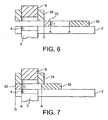
- Fig. 6 the upper piston (9) is shown retracted in the guide sleeve (24), away from the piston chamber (4).
- Dosing means (20) is located at position C, with the bottom of the dosing cavity being closed by its contact with the surface of die (2).
- the plates (22, 23) which form the dosing means (20) are aligned at position A, to provide a dosage cavity (21) of a volume required for receiving a specified amount of powder. In this position, the relative positions of the plates (22, 23) provide a cavity (21) that is larger than the finished volume of the compacted powder slug, thereby accommodating the larger volume of the lower bulk density powder.
- the dosage cavity (21) may be overfilled with powder, and any excess powder removed as the dosing means is slid into position D, with the dosing cavity over the entrance of the piston chamber (4), as shown in Fig. 7 .
- the upper piston (9) is pushed down through the dosing cavity (21) and into the piston chamber (4).
- the powder in the chamber is subjected to compressive forces which compact the powder into a slug or tablet.
- the piston (9) is retracted back into the guide sleeve (24) and the dosing means (20) slid back into position C.
- FIG. 10 shows the preferred apparatus in substantially the same state as Fig. 6 albeit that a powder supply conduit (40) is shown abutting the plates (22) and (23) from above.
- the powder supply conduit (40) extends between a powder hopper or similar storage receptacle (not shown) and dosing cavity (21).
- powder is supplied to the dosing cavity (21) via the powder supply conduit (40), by any suitable mechanism.
- the powder charge in the dosing cavity (21) is transferred to the piston chamber as the plates (22,23) are slid from position C to position D and the plates (22,23) are drawn together.
- the powder is then compacted as described with reference to Fig.9 .
- Figs. 11 and 12 illustrate a preferred embodiment of dosing means adapted for use on a machine with an array of adjacent powder compaction chambers. Such machines are used to manufacture large volumes of products and may have many such arrays.
- the powder dosing and compaction unit of Fig. 11 is an assembly of parts that is mounted above the die 62 and is connected to the bulk powder supply. It has two key functions:
- this unit may also cut the film that has been formed into the cavities.
- the quantity of powder is controlled by a dosage mechanism (50), which consists of two slideably interleaved finger plates (52), (53) that fit together as shown in Fig. 11 to create dosing cavities (54) of adjustable sectional area.
- the depth of engagement of these two plates (52), (53) thus controls the volume of the cavities.
- the assembly of these two plates is slideably mounted such that the cavities can be moved horizontally on die (62) between position D, where the powder is compressed into a slug or tablet form, see Fig. 12 .
- the compaction chambers below plate (53) are not shown on Fig. 12 .
- an agitator (72) mounted above the fill area within the powder hopper.
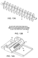
- This consists of a shaft with "vanes" of the form shown in Figs.13A and 13B .
- This agitator is not a spiral screw. When the shaft is rotated the vanes agitate the powder gently without compressing it and thus promote a consistent supply of free flowing powder.
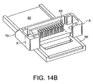
- Fig. 14A shows the agitator (72) mounted in a housing (70) which is above the dosing cavities (54).
- compression of the powder is achieved by means of a row of pistons 82 that are mounted in the housing (70) above position 'D'.
- the pistons pass through bores formed by the finger plates (52), and the die 2 to perform compaction against a base provided from below.
- finger plates (52), (53) and surrounding parts corresponds generally to that described herein before with respect to Figs.5-10 , with the plates (52), (53) of dosage mechanism (50) respectively, corresponding to plates (22), (23) of the dosage means (20).
- the plates (52), (53) are moved together such that the dosing cavities are translated to a position D above the compaction chambers and below the pistons.
- preferred embodiments provide a variable volume chamber adapted to cope with powders of varying physical properties, which chamber when correctly adjusted to receive the required charge of powder causes the production of dosage forms of the required mass and size. Further, since the powder charge is supplied from the hopper to the compaction chamber entirely within a closed system (i.e. without being exposed to the surrounding environment) the amount of dust generated in use is reduced or eliminated.
- the apparatus of the present invention may be used to produce coated or uncoated compacted powders. If a coating is required, the apparatus is most suitably employed in step c of the coating/enrobing processes illustrated in Figs. 1 to 4 .
Landscapes
- Health & Medical Sciences (AREA)
- Engineering & Computer Science (AREA)
- Mechanical Engineering (AREA)
- General Health & Medical Sciences (AREA)
- Veterinary Medicine (AREA)
- Pharmacology & Pharmacy (AREA)
- Life Sciences & Earth Sciences (AREA)
- Animal Behavior & Ethology (AREA)
- Chemical & Material Sciences (AREA)
- Public Health (AREA)
- Medicinal Chemistry (AREA)
- Medicinal Preparation (AREA)
- Medical Preparation Storing Or Oral Administration Devices (AREA)
- Processing And Handling Of Plastics And Other Materials For Molding In General (AREA)
- Manufacturing Of Micro-Capsules (AREA)
- Coloring Foods And Improving Nutritive Qualities (AREA)
- Mixers Of The Rotary Stirring Type (AREA)
Description
- This invention concerns apparatus for compacting a powder. More particularly, though not exclusively, this invention concerns apparatus for producing a dosage form comprising a compacted powder, which powder includes a medicament and/or a dietary supplement, such as a vitamin.
- Dosage forms comprising compacted powders including pharmaceuticals, vitamins and/or other dietary supplements for human ingestion are well known. Additionally, compacted powder dosage forms are used with industrial and domestic detergents and the like.
- Powders or mixtures of powders required to be compacted in various applications have variable physical properties. For example, one powder may differ from another in terms of one or more of volume, density, flowability and compressibility. Such physical differences cause problems in powder compaction devices or presses where dosing cavities are required to be part filled or over filled and/or the compacted product deviates from the optimal the size or mass.
- Tablets are a common type of a dosage form and various means for improving their properties have been tried. Current methods for coating tablets, such as pharmaceutical tablets, include the using of acelacoaters or pan coaters, which spray e.g. low molecular weight HPMC grades onto tablets so imparting a surface layer, which is uniform and smooth, but opaque and low gloss. It is possible for the tablets to have embossed lettering on them. This method of coating tablets is however time consuming and requires a high level of expertise to produce satisfactory results. Production complications such as tablet twinning are common, where two tablets become attached to one another during the spray coating operation. In addition to these problems it is necessary to compact the tablets under relatively high pressures so that they do not disintegrate during the coating process. This high level of compaction can have an adverse effect on the disintegration and dissolution rates of active ingredients contained within the capsule, for example, leading to a delay in the release of a drug to a patient, whilst the tablet slowly dissolves in the stomach of the patient.
- An alternative to spray or pan coating is to use two-piece hard capsules. These are produced by a dipping process, typically a HPMC solution is used, producing half shells which interlock and thus produce an enclosed capsule. These capsules are typically opaque but glossy, and cannot have any form of embossment, as this would interfere with the overlap interlocking process. The nature of the capsule dictates that there will always be an airspace above the powder fill level. Additionally, it is not possible to compact the powder into these tablets, and this so limits the quantity of powder which can be encapsulated. It follows that this lack of compaction can, effectively reduce the amount of e.g. medicament which can be encapsulated. The existence of the air space in the capsule and lack of compaction of the powder contained within the capsule leads to a capsule that is inevitably larger than necessary.
- It has also been found that, after manufacture and/or sale of two-piece hard capsules, the capsules can be easily and illegally interfered with, as it is possible to separate the two halves of the capsule and tamper with its contents and replace the two halves back together without there being any obvious change in the capsule's external appearance such to suggest to the user that there was anything wrong with the capsule. This means that it can be difficult to detect capsules which have had their contents tampered with. HPMC and certain other non-gelatin materials are suitable for ingestion by humans, so delivery capsules with gelatin walls find potential use as ingestible capsules, e.g. for the delivery of accurately metered doses of pharmaceutical preparations and dietary supplements, as a possible replacement for gelatin based capsules. Conventional tablets have already been enrobed. See for example
WO-A-02098394 - In
EP-B-0493489 , compacted powder cores comprising a medicine are enrobed with a biodegradable and/or water soluble film, for example a non-gelatin film, such as hydroxypropyl methyl cellulose (HPMC), to produce dosage forms comprising encapsulated bodies of compacted powder. -
WO-A-03096963 - Dispensing the powder into the piston chamber can produce dust, which dust may affect the efficient functioning of the coating machinery and/or cause a health hazard to workers who may become exposed to the dust (which is especially problematical if the dust comprises particles of a pharmaceutical).
-
FR-A-2607066 - The present invention seeks to provide an improved powder compaction apparatus.
- The invention, in its various aspects is as set out in the accompanying claims.
- According to a first aspect of the present invention, there is provided an apparatus for compacting a powder comprising:
- i) A compaction chamber having an entrance;
- ii) Dosing means adapted to dispense a powder through said entrance and into said compaction chamber; and
- iii) A powder supply;
- Wherein said dosing means comprises a plurality of juxtaposed components between which components is formed a dosing cavity for receiving powder from the powder supply and for dispensing powder to the compaction chamber, wherein the volume of the dosing cavity and at least the cross-sectional area of the cavity perpendicular to the direction of flow of the powder when the powder is dispensed into the compaction chamber are variable by adjustment of the respective positions of the juxtaposed components.
- In one embodiment of the present invention, the dosing means comprises at least two, though two are preferred, juxtaposed plates with interleaving parts which together form a dosing cavity.
- The dosing means is movable between a first position, where the powder is received into the dosing cavity, and a second position, where the powder is dispensed from the dosing cavity into the piston chamber of the die.
- Preferably, the components of the dosing means are adjustable such that in the first position the dosing cavity is capable of receiving a specific volume of powder, which powder has a known composition and bulk density. When the dosing means is moved into the second position, the dosing cavity is over the entrance to the piston chamber and the powder is capable of being dispensed into the chamber. In this second position, the juxtaposed components are adjusted until the cross-sectional area of the dosing cavity is reduced to the point where it is substantially the same as the cross-sectional area of the piston chamber, thereby to ensure that substantially all of the powder is dispensed into the chamber.
- After all or a major proportion of the powder has been dispensed into the piston chamber it is compacted by the action of the piston moving into the chamber.
- The dosing means may be removed before the piston is permitted to enter the piston chamber. However, in a preferred embodiment, the dosing means remains in position over the entrance to the piston chamber and the piston enters the chamber by passing through the dosing cavity (the components of the dosing means having been adjusted to provide the cavity with a cross-sectional area substantially the same as the piston chamber).
- Preferably, the apparatus comprises a plurality of dies and pistons and the dosage means comprises sufficient components to provide a plurality of interleaving parts which form a dosage cavity for each piston and die. The dosage means may comprise two plates with multiple interleaving parts. For example, one plate may comprise a plurality of slots into which a plurality of fingers on the other plate may slide, wherein a plurality of dosage cavities are formed between the end of the fingers and the base of the slots. In this way, the apparatus of the invention may be employed to mass produce compacted powders.
- The apparatus of the invention is advantageously employed to reduce the amount of dust formed in powder compacting processes.
- Whilst the invention is preferably employed in the preparation of coated or uncoated compacted powders comprising pharmaceutical and/or diet supplements, the invention is not so limited and may be used in the formation of any coated or uncoated compacted powders. The apparatus of the invention is preferably used in any of the four methods of forming encapsulated compacted powder slugs disclosed in
WO-A-03096963 - This invention is now further described in detail, by way of example only, with reference to the drawings in which:
-
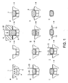
Fig. 1 shows the various stages of a powder compaction/enrobing process disclosed inWO-A-03096963 -
Fig. 2 shows the various stages of another powder compaction/enrobing process disclosed inWO-A-03096963 -
Fig. 3 shows the various stages of yet another powder compaction/enrobing process disclosed inWO-A-03096963 -
Fig. 4 shows the various stages of yet another powder compaction/enrobing process disclosed inWO-A-03096963 -
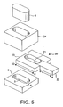
Fig. 5 is a perspective view of a preferred apparatus in accordance with the present invention; -
Figs. 6 to 9 are sectional views through the vertical center line of the preferred apparatus shown inFig. 5 , and depict the four stages of operation of the apparatus; -
Fig.10 is a sectional view through the vertical centre line of the preferred apparatus, showing a powder supply conduit; -
Fig. 11 shows an embodiment of dosing mechanism capable of high volume productions; -
Fig. 12 shows the embodiment ofFig. 11 mounted on adie 62; -
Figs 13A & 13B show an agitator which may be used with embodiment ofFig. 11 ; -
Figs 14A &14B show an assembly for a powder compaction apparatus incorporating the dosing mechanism ofFig. 11 . -
-
FIG. 1 shows the mechanism of the basic steps of powder compaction and enrobement via steps a-1 ofWO-A-03096963 - a. A first film (1) is laid upon a die (2). Lower piston (3), slideable in piston chamber (4), incorporates vacuum port (5).
- b. Film (1) is drawn into and lines chamber (4) by vacuum created by vacuum port (5), to form a pocket shape.
- c. A quantity of powder (6), delivered to the entrance of the chamber (4) in a dosing means (20) comprising a single plate having a dosing cavity (21) therein, is introduced over the pocket of film. Upper piston (9) moves downward, passing through the dosing cavity, towards the lower piston (3), forcing the powder (6) into the chamber (4) and compressing it.
- d. A compacted powder slug (7) resulting from the completion of step c remains in the chamber (4) when the upper piston (9) is withdrawn.
- e. Cutting of film by the introduction of cutting tool (10) to form an isolated semi enrobed slug of compacted powder.
- f. Lower piston (3) begins to move upwards, thereby also urging compacted powder slug (7) upwards.
- g. Lower piston (3) comes to rest, positioning compacted powder slug (7) proud of die (2).
- h. Introduction of a second film (8) over die (2) and also loosely stretching over compacted powder slug (7).
- i. Second vacuum is applied drawing second film (8) around and closely in association with the upper portion of compacted powder slug (7), second film (8) thereby wrapping itself around the upper part of the compacted powder slug (7).
- j. Cutting tool (12) descending and trimming off excess unwrapped film from powder slug (7).
- k. Fully enrobed powder slug, has been ejected from chamber (4) by the further upward movement of lower piston (3) and has the loose ends of the films ironed and sealed by irons (13).
- l. Shows a fully enrobed tablet with ironed seams.
-
FIG. 2 depicts a variation of the basic process described byFIG. 1 .
Steps al and bl show a second pre-formed film pocket, formed by a second vacuum forming pocket (14) being lowered onto the die immediately above a partially enrobed powder slug as shown in step f ofFIG. 1 . Once the opposing film pocket is in position lower piston (3) moves upwards thus pushing compacted partially enrobed powder slug also upwards and into the cavity of the second pre-formed film pocket, thus capping the partially enrobed powder slug to form a fully enrobed capsule, enrobed by two pockets of film. The capsule is then released, trimmed and ironed as mentioned previously. -
FIG. 3 depicts a further variation of the basic process described byFIG. 1 .
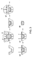
Step a2 shows a powder slug as in step f ofFIG. 1 , and likeFIG. 2 a second pre-formed film pocket is introduced, but this time it is a shallow pocket, formed by a second shallow vacuum forming pocket (15), such to only coat the top of the powder slug and to form a seal at the circumference of the very edge of the cylindrical portion of the powder slug. Steps a2-d2 show this revised process. This process gives rise to a capsule with a different type of seal which gives rise to different properties in the capsule. -
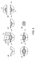
FIG. 4 depicts another variation of the process described byFIG. 1 .
However the basic process is essentially duplicated to form a capsule which contains two distinct half doses of powder. The basic process as described inFIG. 1 is carried out up to step f, in duplicate, which is basically steps a3-c3 inFIG. 4 . The main differences at this point inFIG. 4 , are that the two opposing pockets filled with compacted powder (16,17) are half size in depth, and the top of the powder slugs are essentially flat, rather than rounded. Step c3 may include the laying down of an intermediate film on the surface of the half slug. Steps d3-f3 show the bringing together of 2 half slugs to form a single capsule, comprised of 2 parts. Step g3 shows a compartmentalized capsule. The advantages are at least 2 separate doses of active ingredients can be incorporated into 1 capsule, under perhaps different compaction pressures etc. This gives rise to further flexibility and options as to the performance of the new dosage forms. -
Fig. 5 shows a preferred embodiment of the apparatus of the present invention. The apparatus comprises a die (2), including a lower piston (3), incorporating a vacuum port (not shown), slideable in piston chamber (4). Dosing means (20) comprises two juxtaposed plates (22, 23) which interleave to form dosing cavity (21). The cross-sectional area of the cavity (21) (and consequently the volume of the cavity as well) may be increased or decreased by moving plate (22) relative to plate (23) in direction A or B, respectively. The dosing means (20) may be moved so that the dosing cavity (21) is away from or over the entrance of the piston chamber (4) by sliding it in direction C or D, respectively. When the dosing cavity is over the entrance of the piston chamber, upper piston (9) passes through the dosing cavity (21) to enter the piston chamber (4). The piston (9) is aligned over the die (3) by means of a guide sleeve (24). - In use, the apparatus of
Fig. 5 is aligned and operated as illustrated inFigs. 6 to 9 . Upper die (9) and guide sleeve (24) are shown orientated above the entrance of piston chamber (4) of die (2). Lower piston (3) is in its lowered position, forming the bottom of piston chamber (4). - In
Fig. 6 , the upper piston (9) is shown retracted in the guide sleeve (24), away from the piston chamber (4). Dosing means (20) is located at position C, with the bottom of the dosing cavity being closed by its contact with the surface of die (2). The plates (22, 23) which form the dosing means (20) are aligned at position A, to provide a dosage cavity (21) of a volume required for receiving a specified amount of powder. In this position, the relative positions of the plates (22, 23) provide a cavity (21) that is larger than the finished volume of the compacted powder slug, thereby accommodating the larger volume of the lower bulk density powder. - The dosage cavity (21) may be overfilled with powder, and any excess powder removed as the dosing means is slid into position D, with the dosing cavity over the entrance of the piston chamber (4), as shown in
Fig. 7 . - As shown in
Fig. 8 , when the cavity (21) is over the piston chamber (4), powder is urged to fall into the piston chamber as the plates (22, 23) are drawn together to position B. Typically, this occurs by further movement ofplate 22 towardsplate 23, which remains stationary over the piston chamber. As the plates (22, 23) are drawn together, thereby reducing the volume and the cross-sectional area of the cavity, any powder that sits on the surface of the die is thereby swept into the piston chamber. Movement of the plates (22, 23) is stopped when the cro ss-sectional area of the cavity (21) is substantially the same as the cross-sectional area of the chamber (4). - As shown in
Fig. 9 , the upper piston (9) is pushed down through the dosing cavity (21) and into the piston chamber (4). The powder in the chamber is subjected to compressive forces which compact the powder into a slug or tablet. - Once the powder has been compacted, the piston (9) is retracted back into the guide sleeve (24) and the dosing means (20) slid back into position C.
-
FIG. 10 shows the preferred apparatus in substantially the same state asFig. 6 albeit that a powder supply conduit (40) is shown abutting the plates (22) and (23) from above. The powder supply conduit (40) extends between a powder hopper or similar storage receptacle (not shown) and dosing cavity (21). - In use, powder is supplied to the dosing cavity (21) via the powder supply conduit (40), by any suitable mechanism. The powder charge in the dosing cavity (21) is transferred to the piston chamber as the plates (22,23) are slid from position C to position D and the plates (22,23) are drawn together. The powder is then compacted as described with reference to
Fig.9 . -
Figs. 11 and 12 illustrate a preferred embodiment of dosing means adapted for use on a machine with an array of adjacent powder compaction chambers. Such machines are used to manufacture large volumes of products and may have many such arrays. - The powder dosing and compaction unit of
Fig. 11 is an assembly of parts that is mounted above thedie 62 and is connected to the bulk powder supply. It has two key functions: - a. to accurately control the quantity of powder that is placed into each cavity.
- b. to remove excess powder and compress the powder in piston cavities.
- Where the compacted product is coated or enrobed this unit may also cut the film that has been formed into the cavities.
- The quantity of powder is controlled by a dosage mechanism (50), which consists of two slideably interleaved finger plates (52), (53) that fit together as shown in
Fig. 11 to create dosing cavities (54) of adjustable sectional area. The depth of engagement of these two plates (52), (53) thus controls the volume of the cavities. The assembly of these two plates is slideably mounted such that the cavities can be moved horizontally on die (62) between position D, where the powder is compressed into a slug or tablet form, seeFig. 12 . The compaction chambers below plate (53) are not shown onFig. 12 . - To ensure that the cavities in the finger plates completely fill with powder there is an agitator (72) mounted above the fill area within the powder hopper. This consists of a shaft with "vanes" of the form shown in
Figs.13A and 13B . This agitator is not a spiral screw. When the shaft is rotated the vanes agitate the powder gently without compressing it and thus promote a consistent supply of free flowing powder. -
Fig. 14A shows the agitator (72) mounted in a housing (70) which is above the dosing cavities (54). With reference toFig.14A and14B compression of the powder is achieved by means of a row ofpistons 82 that are mounted in the housing (70) above position 'D'. The pistons pass through bores formed by the finger plates (52), and thedie 2 to perform compaction against a base provided from below. - In this way powder can be compacted into a series of piston chambers to generate a plurality of products simultaneously. The strokes of the
compression pistons 82 are generally controlled to ensure a fixed size for the finishing slugs or tablets. A skilled person will appreciate that compaction means other than pistons, e.g. air pulses, may be used in the alternative. - The action of finger plates (52), (53) and surrounding parts corresponds generally to that described herein before with respect to
Figs.5-10 , with the plates (52), (53) of dosage mechanism (50) respectively, corresponding to plates (22), (23) of the dosage means (20). In this case, the plates (52), (53) are moved together such that the dosing cavities are translated to a position D above the compaction chambers and below the pistons. - From the foregoing description it will be appreciated that preferred embodiments provide a variable volume chamber adapted to cope with powders of varying physical properties, which chamber when correctly adjusted to receive the required charge of powder causes the production of dosage forms of the required mass and size. Further, since the powder charge is supplied from the hopper to the compaction chamber entirely within a closed system (i.e. without being exposed to the surrounding environment) the amount of dust generated in use is reduced or eliminated.
- The apparatus of the present invention may be used to produce coated or uncoated compacted powders. If a coating is required, the apparatus is most suitably employed in step c of the coating/enrobing processes illustrated in
Figs. 1 to 4 .
Claims (8)
- Apparatus for compacting a powder comprising:i) a compaction chamber (4), having an entrance;ii) dosing means (20; 50) adapted to dispense a powder through said entrance and into said compaction chamber; andvi) a powder supply;wherein said dosing means (20; 50) comprises a plurality of juxtaposed components (22,23; 52,53) between which components is formed a dosing cavity (21) for receiving powder from the powder supply and for dispensing powder to the compaction chamber, wherein the volume of the dosing cavity (21) and at least the cross-sectional area of the cavity perpendicular to the direction of flow of the powder when the powder is dispensed into the compaction chamber (4) are variable by adjustment of the respective positions of the juxtaposed components (22,23; 52,53).
- Apparatus as claimed in claim 1, wherein the dosing means (20,50) comprises at least two juxtaposed plates (22,23; 52,53) with interleaving parts which together form a dosing cavity (21; 54).
- Apparatus as claimed in claim 1 or claim 2, wherein the dosing means (20,50) is movable between a first position, where the powder is received into the dosing cavity (21; 54), and a second position, where the powder is dispensed from the dosing cavity into the compaction chamber (4).
- Apparatus as claimed in claim 3, wherein the components (22,23; 52,53) of the dosing means (20; 50) are adjustable such that in the first position the dosing cavity (21; 54) receives a specific volume of powder, which powder has a known composition and bulk density, and wherein when the dosing means is moved into the second position, the dosing cavity (21; 54) is over the entrance to the compaction chamber (4) and the powder can be dispensed into the chamber.
- Apparatus as claimed in claim 4, wherein when the dosing means (20; 50) is in the second position, the juxtaposed components may be adjusted until the cross-sectional area of the dosing cavity is reduced to the point where it is substantially the same as the cross-sectional area of the compaction chamber.
- Apparatus as claimed in claim 5, wherein when the dosing means remains in position over the entrance to the compaction chamber, a piston is able to enter the chamber by passing through the dosing cavity.
- Apparatus as claimed in claim 6, wherein before the piston (9; 82) passes through the dosing cavity (21; 54), the components (22, 23; 52, 53) of the dosing means (20; 50) are adjusted to provide the cavity with a cross-sectional area substantially the same as the cross-sectional area of the piston chamber.
- Apparatus as claimed in any one of the preceding claims wherein the apparatus comprises a plurality of dies and compaction means and the dosage means comprises sufficient components to provide a dosage cavity for each compaction means and die.
Priority Applications (2)
| Application Number | Priority Date | Filing Date | Title |
|---|---|---|---|
| EP08154935A EP1972319A3 (en) | 2003-09-24 | 2004-09-24 | Apparatus for compacting powder |
| EP08154934A EP1946737B1 (en) | 2003-09-24 | 2004-09-24 | Apparatus for compacting powder |
Applications Claiming Priority (2)
| Application Number | Priority Date | Filing Date | Title |
|---|---|---|---|
| GBGB0322358.3A GB0322358D0 (en) | 2003-09-24 | 2003-09-24 | Improvements in powder compaction and enrobing |
| PCT/GB2004/004092 WO2005030115A1 (en) | 2003-09-24 | 2004-09-24 | Apparatus for compacting powder |
Related Child Applications (2)
| Application Number | Title | Priority Date | Filing Date |
|---|---|---|---|
| EP08154935A Division EP1972319A3 (en) | 2003-09-24 | 2004-09-24 | Apparatus for compacting powder |
| EP08154934A Division EP1946737B1 (en) | 2003-09-24 | 2004-09-24 | Apparatus for compacting powder |
Publications (2)
| Publication Number | Publication Date |
|---|---|
| EP1667628A1 EP1667628A1 (en) | 2006-06-14 |
| EP1667628B1 true EP1667628B1 (en) | 2008-12-17 |
Family
ID=29266577
Family Applications (9)
| Application Number | Title | Priority Date | Filing Date |
|---|---|---|---|
| EP08100737A Withdrawn EP1908444A1 (en) | 2003-09-24 | 2004-09-24 | Improvements in powder compaction and enrobing |
| EP08154935A Withdrawn EP1972319A3 (en) | 2003-09-24 | 2004-09-24 | Apparatus for compacting powder |
| EP08100743A Expired - Lifetime EP1908448B1 (en) | 2003-09-24 | 2004-09-24 | Improvements in powder compaction and enrobing |
| EP08100742A Withdrawn EP1908447A3 (en) | 2003-09-24 | 2004-09-24 | Improvements in powder compaction and enrobing |
| EP04768636A Expired - Lifetime EP1667628B1 (en) | 2003-09-24 | 2004-09-24 | Apparatus for compacting powder |
| EP08100740A Withdrawn EP1908446A1 (en) | 2003-09-24 | 2004-09-24 | Improvements in powder compaction and enrobing |
| EP08154934A Expired - Lifetime EP1946737B1 (en) | 2003-09-24 | 2004-09-24 | Apparatus for compacting powder |
| EP04768641A Expired - Lifetime EP1670412B1 (en) | 2003-09-24 | 2004-09-24 | Improvements in powder compaction and enrobing |
| EP08100739A Withdrawn EP1908445A1 (en) | 2003-09-24 | 2004-09-24 | Improvements in powder compaction and enrobing |
Family Applications Before (4)
| Application Number | Title | Priority Date | Filing Date |
|---|---|---|---|
| EP08100737A Withdrawn EP1908444A1 (en) | 2003-09-24 | 2004-09-24 | Improvements in powder compaction and enrobing |
| EP08154935A Withdrawn EP1972319A3 (en) | 2003-09-24 | 2004-09-24 | Apparatus for compacting powder |
| EP08100743A Expired - Lifetime EP1908448B1 (en) | 2003-09-24 | 2004-09-24 | Improvements in powder compaction and enrobing |
| EP08100742A Withdrawn EP1908447A3 (en) | 2003-09-24 | 2004-09-24 | Improvements in powder compaction and enrobing |
Family Applications After (4)
| Application Number | Title | Priority Date | Filing Date |
|---|---|---|---|
| EP08100740A Withdrawn EP1908446A1 (en) | 2003-09-24 | 2004-09-24 | Improvements in powder compaction and enrobing |
| EP08154934A Expired - Lifetime EP1946737B1 (en) | 2003-09-24 | 2004-09-24 | Apparatus for compacting powder |
| EP04768641A Expired - Lifetime EP1670412B1 (en) | 2003-09-24 | 2004-09-24 | Improvements in powder compaction and enrobing |
| EP08100739A Withdrawn EP1908445A1 (en) | 2003-09-24 | 2004-09-24 | Improvements in powder compaction and enrobing |
Country Status (16)
| Country | Link |
|---|---|
| US (4) | US20110091591A1 (en) |
| EP (9) | EP1908444A1 (en) |
| JP (2) | JP2007506499A (en) |
| KR (1) | KR100838831B1 (en) |
| CN (1) | CN1882303A (en) |
| AR (1) | AR046028A1 (en) |
| AT (4) | ATE417591T1 (en) |
| AU (1) | AU2004275563A1 (en) |
| BR (2) | BRPI0414712A (en) |
| CA (1) | CA2540101A1 (en) |
| DE (4) | DE602004014003D1 (en) |
| ES (1) | ES2308236T3 (en) |
| GB (1) | GB0322358D0 (en) |
| IL (2) | IL174424A0 (en) |
| TW (1) | TW200526192A (en) |
| WO (3) | WO2005030379A1 (en) |
Families Citing this family (82)
| Publication number | Priority date | Publication date | Assignee | Title |
|---|---|---|---|---|
| CN101404892B (en) | 2002-05-14 | 2012-04-04 | Fmc有限公司 | microcrystalline cellulose composition |
| US20080126195A1 (en) | 2004-07-22 | 2008-05-29 | Ritter Andrew J | Methods and Compositions for Treating Lactose Intolerance |
| US7879382B2 (en) * | 2005-09-30 | 2011-02-01 | Fmc Corporation | Stabilizers and compositions and products comprising same |
| GB0522188D0 (en) * | 2005-10-31 | 2005-12-07 | Bioprogress Technology Ltd | Apparatus for tablet coating |
| WO2008008120A1 (en) * | 2006-07-14 | 2008-01-17 | Fmc Corporation | Solid form |
| JP2010522135A (en) | 2006-10-09 | 2010-07-01 | チャールストン ラボラトリーズ,インコーポレイテッド | Pharmaceutical composition |
| EP2076249A2 (en) * | 2006-10-27 | 2009-07-08 | FMC Corporation | Dry granulation binders, products, and use thereof |
| EP1952696A1 (en) * | 2007-02-01 | 2008-08-06 | Nestec S.A. | A method and apparatus for making centre-filled shaped food products |
| KR100912351B1 (en) * | 2007-02-14 | 2009-08-14 | 한미약품 주식회사 | Method for preparing rapidly disintegrating formulation for oral administration and medicine packing machine for the same |
| KR20090110939A (en) * | 2007-02-19 | 2009-10-23 | 데이진 화-마 가부시키가이샤 | Transmission board |
| US20080311162A1 (en) * | 2007-05-16 | 2008-12-18 | Olivia Darmuzey | Solid form |
| US20080286343A1 (en) * | 2007-05-16 | 2008-11-20 | Dzenana Cengic | Solid form |
| EP2170282A4 (en) | 2007-06-27 | 2014-11-05 | Hanmi Pharm Ind Co Ltd | METHOD FOR PREPARING RAPID DISAGGREGATION FORMULATION FOR ORAL ADMINISTRATION AND APPARATUS FOR PREPARING AND PACKAGING THEREFOR |
| CN102424151B (en) * | 2007-06-27 | 2014-03-12 | 韩美药品株式会社 | Apparatus for preparing rapidly disintegrating formulation for oral administration |
| GB0714811D0 (en) * | 2007-07-31 | 2007-09-12 | Reckitt Benckiser Nv | Improvements in or relating to compositions |
| KR101560176B1 (en) | 2007-10-31 | 2015-10-14 | 맥네일-피피씨, 인코포레이티드 | Orally disintegrated dosage form |
| US20110223248A1 (en) * | 2007-12-12 | 2011-09-15 | Ritter Pharmaceuticals, Inc. | Methods and compositions for treating lactose intolerance |
| JP5714910B2 (en) | 2008-01-09 | 2015-05-07 | チャールストン ラボラトリーズ,インコーポレイテッド | Pharmaceutical composition |
| US8785160B2 (en) | 2009-02-24 | 2014-07-22 | Ritter Pharmaceuticals, Inc. | Prebiotic formulations and methods of use |
| SG10201901259RA (en) | 2009-02-24 | 2019-03-28 | Ritter Pharmaceuticals Inc | Prebiotic formulations and methods of use |
| EP3311667A1 (en) | 2009-07-08 | 2018-04-25 | Charleston Laboratories, Inc. | Pharmaceutical compositions |
| US8343533B2 (en) | 2009-09-24 | 2013-01-01 | Mcneil-Ppc, Inc. | Manufacture of lozenge product with radiofrequency |
| TWI461213B (en) | 2009-11-05 | 2014-11-21 | Fmc Corp | Microcrystalline cellulose and calcium phosphate compositions useful as pharmaceutical excipients |
| TW201129386A (en) | 2009-11-05 | 2011-09-01 | Fmc Corp | Microcrystalline cellulose and calcium phosphate compositions useful as pharmaceutical excipients |
| WO2011087629A2 (en) | 2009-12-22 | 2011-07-21 | Fmc Corporation | Microcrystalline cellulose and calcium carbonate compositions useful as recompactible pharmaceutical excipients |
| IT1397610B1 (en) * | 2009-12-22 | 2013-01-18 | Mg 2 Srl | INTERMITTENT ROTARY MACHINE FOR FILLING CAPSULES WITH PHARMACEUTICALS. |
| CN103857739B (en) | 2011-10-05 | 2017-04-19 | Fmc有限公司 | Stabilizer composition, preparation method and application of co-ground microcrystalline cellulose and carboxymethyl cellulose |
| JP6188030B2 (en) | 2011-10-05 | 2017-08-30 | エフ エム シー コーポレーションFmc Corporation | Stabilizer composition for microcrystalline cellulose and carboxymethylcellulose, method for producing the composition, and food product |
| CN104010522A (en) | 2011-12-09 | 2014-08-27 | Fmc有限公司 | Co-Milled Stabilizer Composition |
| JP2015509788A (en) | 2012-02-29 | 2015-04-02 | パルマトリックス,インコーポレイテッド | Dry powder suitable for inhalation |
| US8986483B2 (en) | 2012-04-02 | 2015-03-24 | Whirlpool Corporation | Method of making a folded vacuum insulated structure |
| US9221210B2 (en) | 2012-04-11 | 2015-12-29 | Whirlpool Corporation | Method to create vacuum insulated cabinets for refrigerators |
| US9445971B2 (en) | 2012-05-01 | 2016-09-20 | Johnson & Johnson Consumer Inc. | Method of manufacturing solid dosage form |
| US9233491B2 (en) * | 2012-05-01 | 2016-01-12 | Johnson & Johnson Consumer Inc. | Machine for production of solid dosage forms |
| US9511028B2 (en) | 2012-05-01 | 2016-12-06 | Johnson & Johnson Consumer Inc. | Orally disintegrating tablet |
| KR101390857B1 (en) * | 2012-06-22 | 2014-05-02 | 최경복 | surface coating method and surface coating machine of slag ball |
| EP2703299B1 (en) | 2012-08-31 | 2016-03-30 | CareFusion Switzerland 317 Sarl | A storage and dosing station for storage and dispensing dosed quantities of solid drug portions |
| WO2014184364A1 (en) * | 2013-05-16 | 2014-11-20 | Korsch Ag | Device and method for depositing films in tablet presses |
| DE102013211305A1 (en) * | 2013-06-17 | 2014-12-18 | Horst Zerhoch | Tablet press and method of making a tablet |
| US9789066B2 (en) | 2014-01-10 | 2017-10-17 | Johnson & Johnson Consumer Inc. | Process for making tablet using radiofrequency and lossy coated particles |
| US9689604B2 (en) | 2014-02-24 | 2017-06-27 | Whirlpool Corporation | Multi-section core vacuum insulation panels with hybrid barrier film envelope |
| US10052819B2 (en) | 2014-02-24 | 2018-08-21 | Whirlpool Corporation | Vacuum packaged 3D vacuum insulated door structure and method therefor using a tooling fixture |
| US9599392B2 (en) | 2014-02-24 | 2017-03-21 | Whirlpool Corporation | Folding approach to create a 3D vacuum insulated door from 2D flat vacuum insulation panels |
| EP3125905A4 (en) | 2014-04-04 | 2017-11-08 | Ritter Pharmaceuticals, Inc. | Methods and compositions for microbiome alteration |
| US9476633B2 (en) | 2015-03-02 | 2016-10-25 | Whirlpool Corporation | 3D vacuum panel and a folding approach to create the 3D vacuum panel from a 2D vacuum panel of non-uniform thickness |
| US10161669B2 (en) | 2015-03-05 | 2018-12-25 | Whirlpool Corporation | Attachment arrangement for vacuum insulated door |
| US9897370B2 (en) | 2015-03-11 | 2018-02-20 | Whirlpool Corporation | Self-contained pantry box system for insertion into an appliance |
| US9441779B1 (en) | 2015-07-01 | 2016-09-13 | Whirlpool Corporation | Split hybrid insulation structure for an appliance |
| US10429125B2 (en) | 2015-12-08 | 2019-10-01 | Whirlpool Corporation | Insulation structure for an appliance having a uniformly mixed multi-component insulation material, and a method for even distribution of material combinations therein |
| US11052579B2 (en) | 2015-12-08 | 2021-07-06 | Whirlpool Corporation | Method for preparing a densified insulation material for use in appliance insulated structure |
| US10422573B2 (en) | 2015-12-08 | 2019-09-24 | Whirlpool Corporation | Insulation structure for an appliance having a uniformly mixed multi-component insulation material, and a method for even distribution of material combinations therein |
| US10222116B2 (en) | 2015-12-08 | 2019-03-05 | Whirlpool Corporation | Method and apparatus for forming a vacuum insulated structure for an appliance having a pressing mechanism incorporated within an insulation delivery system |
| US10041724B2 (en) | 2015-12-08 | 2018-08-07 | Whirlpool Corporation | Methods for dispensing and compacting insulation materials into a vacuum sealed structure |
| US12508751B2 (en) | 2015-12-08 | 2025-12-30 | Whirlpool Corporation | Insulation compaction device and method for forming an insulated structure for an appliance |
| US10422569B2 (en) | 2015-12-21 | 2019-09-24 | Whirlpool Corporation | Vacuum insulated door construction |
| US9752818B2 (en) | 2015-12-22 | 2017-09-05 | Whirlpool Corporation | Umbilical for pass through in vacuum insulated refrigerator structures |
| US9840042B2 (en) | 2015-12-22 | 2017-12-12 | Whirlpool Corporation | Adhesively secured vacuum insulated panels for refrigerators |
| US10610985B2 (en) | 2015-12-28 | 2020-04-07 | Whirlpool Corporation | Multilayer barrier materials with PVD or plasma coating for vacuum insulated structure |
| US10018406B2 (en) | 2015-12-28 | 2018-07-10 | Whirlpool Corporation | Multi-layer gas barrier materials for vacuum insulated structure |
| US10030905B2 (en) | 2015-12-29 | 2018-07-24 | Whirlpool Corporation | Method of fabricating a vacuum insulated appliance structure |
| US10807298B2 (en) | 2015-12-29 | 2020-10-20 | Whirlpool Corporation | Molded gas barrier parts for vacuum insulated structure |
| US11247369B2 (en) | 2015-12-30 | 2022-02-15 | Whirlpool Corporation | Method of fabricating 3D vacuum insulated refrigerator structure having core material |
| JP2019507181A (en) | 2016-03-04 | 2019-03-14 | チャールストン ラボラトリーズ,インコーポレイテッド | Pharmaceutical composition |
| EP3443285B1 (en) | 2016-04-15 | 2021-03-10 | Whirlpool Corporation | Vacuum insulated refrigerator cabinet |
| US11009284B2 (en) | 2016-04-15 | 2021-05-18 | Whirlpool Corporation | Vacuum insulated refrigerator structure with three dimensional characteristics |
| US20180014999A1 (en) * | 2016-07-18 | 2018-01-18 | Jennison Quality Components, Inc. | Apparatus and Method for Filling Capsules |
| US11320193B2 (en) | 2016-07-26 | 2022-05-03 | Whirlpool Corporation | Vacuum insulated structure trim breaker |
| WO2018034665A1 (en) | 2016-08-18 | 2018-02-22 | Whirlpool Corporation | Machine compartment for a vacuum insulated structure |
| US10598424B2 (en) | 2016-12-02 | 2020-03-24 | Whirlpool Corporation | Hinge support assembly |
| US10493026B2 (en) | 2017-03-20 | 2019-12-03 | Johnson & Johnson Consumer Inc. | Process for making tablet using radiofrequency and lossy coated particles |
| WO2019118984A2 (en) | 2017-12-15 | 2019-06-20 | Solarea Bio, Inc. | Microbial compositions and methods for treating type 2 diabetes, obesity, and metabolic syndrome |
| US10907888B2 (en) | 2018-06-25 | 2021-02-02 | Whirlpool Corporation | Hybrid pigmented hot stitched color liner system |
| EP3846830A4 (en) | 2018-09-05 | 2022-07-06 | Solarea Bio, Inc. | METHODS AND COMPOSITIONS FOR THE TREATMENT OF MUSCULOSKELETAL DISEASES |
| US11980647B2 (en) | 2018-09-05 | 2024-05-14 | Solarea Bio, Inc. | Methods and compositions for treating musculoskeletal diseases, treating inflammation, and managing symptoms of menopause |
| US11779522B2 (en) * | 2018-12-07 | 2023-10-10 | Incube Labs, Llc | Apparatus for manufacturing microtablets |
| CA3143713A1 (en) | 2019-06-19 | 2020-12-24 | Solarea Bio, Inc. | Microbial compositions and methods for producing upgraded probiotic assemblages |
| JP2023534162A (en) * | 2020-07-10 | 2023-08-08 | コテックス テクノロジーズ インコーポレイテッド | Coated substrate and method of making same |
| CN113729253B (en) * | 2021-08-20 | 2024-02-27 | 刘清岭 | An edible rice ball rolling and forming equipment |
| TWI842120B (en) * | 2021-10-12 | 2024-05-11 | 日商雷恩自動機股份有限公司 | Forming method of stuffed food |
| EP4436407A1 (en) | 2021-11-22 | 2024-10-02 | Solarea Bio, Inc. | Methods and compositions for treating musculoskeletal diseases, treating inflammation, and managing symptoms of menopause |
| CN114148026A (en) * | 2021-11-26 | 2022-03-08 | 德州德药制药有限公司 | Nifedipine sustained-release tablet tabletting device with detection function and use method thereof |
| US20230190834A1 (en) | 2021-12-21 | 2023-06-22 | Solarea Bio, Inc. | Immunomodulatory compositions comprising microbial entities |
Family Cites Families (33)
| Publication number | Priority date | Publication date | Assignee | Title |
|---|---|---|---|---|
| US2886849A (en) * | 1957-07-03 | 1959-05-19 | Brierley Kenneth | Powder-compressing machines |
| US3096248A (en) * | 1959-04-06 | 1963-07-02 | Rexall Drug & Chemical Company | Method of making an encapsulated tablet |
| GB1024868A (en) * | 1963-08-20 | 1966-04-06 | Novadel Ltd | Improvements in apparatus for agitating powdered material |
| DE1258837B (en) * | 1967-03-10 | 1968-01-18 | Wibau Gmbh | Mixing device |
| US3677673A (en) | 1970-08-25 | 1972-07-18 | Pennwalt Corp | Rotary press |
| ZA767136B (en) * | 1975-12-15 | 1977-10-26 | Hoffmann La Roche | Novel dosage form |
| US4325734A (en) * | 1980-03-27 | 1982-04-20 | Mcgraw-Edison Company | Method and apparatus for forming compact bodies from conductive and non-conductive powders |
| US4401614A (en) * | 1981-09-08 | 1983-08-30 | Ptx-Pentronix, Inc. | Anvil assembly for a powder-compacting anvil press |
| JPS6042490A (en) * | 1983-08-17 | 1985-03-06 | Mitsubishi Heavy Ind Ltd | Method and apparatus for measurement of ash deposition rate in coal slurry |
| FR2607066B3 (en) * | 1986-08-12 | 1989-04-21 | Freund Pierre | LOG PRESS, ESPECIALLY FOR COMPACTING FUEL WASTE |
| US4983247A (en) * | 1989-08-07 | 1991-01-08 | General Electric Company | Method for producing resin rich surface layer on composite thermoplastic material |
| US5074102A (en) * | 1989-10-26 | 1991-12-24 | American Cyanamid Company | Flat track modified soft shell capsule filling machine |
| JPH06270175A (en) * | 1991-05-15 | 1994-09-27 | E I Du Pont De Nemours & Co | Insert encapsulated with thermoplastic sheet material by multi-stage compression molding |
| FR2691329B1 (en) * | 1992-05-25 | 2001-11-16 | Sopral Sa | Plant for the compaction of animal feed. |
| JP3179658B2 (en) * | 1994-07-07 | 2001-06-25 | 株式会社三共製作所 | Tablet manufacturing method and device |
| JP3133899B2 (en) * | 1994-07-07 | 2001-02-13 | 株式会社三共製作所 | Tablet manufacturing method and device |
| US5672364A (en) | 1994-07-07 | 1997-09-30 | Sankyo Seisakusho Co. & Eisai Co., Ltd. | Apparatus for manufacturing tablets |
| JP3187657B2 (en) * | 1994-07-08 | 2001-07-11 | 株式会社三共製作所 | Tablet manufacturing method and device |
| JP2694920B2 (en) * | 1994-07-28 | 1997-12-24 | 大日本印刷株式会社 | Injection molding simultaneous painting method and apparatus |
| SE503674C2 (en) * | 1994-11-28 | 1996-07-29 | Flaekt Ab | Device for mixing particulate matter and liquid |
| US5682733A (en) * | 1996-05-09 | 1997-11-04 | Perrone; Aldo | Apparatus for enrobing tablets |
| SE508868C2 (en) * | 1997-03-17 | 1998-11-09 | Flaekt Ab | Device for mixing particulate matter and liquid |
| JP3282988B2 (en) * | 1997-05-01 | 2002-05-20 | アピックヤマダ株式会社 | Resin molding method and resin molding apparatus |
| DE69931133T2 (en) * | 1998-12-28 | 2006-11-23 | Neomax Co., Ltd., Osaka | Method and apparatus for introducing rare earth alloy powder |
| SE0001522L (en) * | 2000-04-27 | 2001-10-28 | Skf Nova Ab | Method and apparatus for compacting a powder material into a homogeneous article |
| US6474371B1 (en) * | 2000-04-28 | 2002-11-05 | Sumitomo Special Metals Co., Ltd. | Powder feeding apparatus, powder feeding method and powder pressing apparatus |
| JP2002307199A (en) * | 2001-04-11 | 2002-10-22 | Kobayashi Kogyo Kk | Powder compression molding method, and device therefor |
| GB0113403D0 (en) * | 2001-06-02 | 2001-07-25 | Bioprogress Tech Int Inc | Tablet enrobing |
| JP2004531399A (en) * | 2001-06-25 | 2004-10-14 | ファルマシア・コーポレーション | Method and apparatus for producing compression-coated tablets |
| GB0120835D0 (en) * | 2001-08-28 | 2001-10-17 | Smithkline Beecham Plc | Process |
| US6837696B2 (en) * | 2001-09-28 | 2005-01-04 | Mcneil-Ppc, Inc. | Apparatus for manufacturing dosage forms |
| US6742646B2 (en) | 2001-09-28 | 2004-06-01 | Mcneil-Ppc, Inc. | Systems, methods and apparatuses for manufacturing dosage forms |
| WO2005016537A2 (en) * | 2003-08-14 | 2005-02-24 | Glenn Beane | Powder feed apparatus, system and method |
-
2003
- 2003-09-24 GB GBGB0322358.3A patent/GB0322358D0/en not_active Ceased
-
2004
- 2004-09-24 DE DE602004014003T patent/DE602004014003D1/en not_active Expired - Lifetime
- 2004-09-24 TW TW093128983A patent/TW200526192A/en unknown
- 2004-09-24 WO PCT/GB2004/004063 patent/WO2005030379A1/en not_active Ceased
- 2004-09-24 EP EP08100737A patent/EP1908444A1/en not_active Withdrawn
- 2004-09-24 JP JP2006527480A patent/JP2007506499A/en active Pending
- 2004-09-24 AT AT04768636T patent/ATE417591T1/en not_active IP Right Cessation
- 2004-09-24 EP EP08154935A patent/EP1972319A3/en not_active Withdrawn
- 2004-09-24 DE DE602004028300T patent/DE602004028300D1/en not_active Expired - Lifetime
- 2004-09-24 EP EP08100743A patent/EP1908448B1/en not_active Expired - Lifetime
- 2004-09-24 EP EP08100742A patent/EP1908447A3/en not_active Withdrawn
- 2004-09-24 AU AU2004275563A patent/AU2004275563A1/en not_active Abandoned
- 2004-09-24 KR KR1020067007924A patent/KR100838831B1/en not_active Expired - Fee Related
- 2004-09-24 US US10/573,087 patent/US20110091591A1/en not_active Abandoned
- 2004-09-24 EP EP04768636A patent/EP1667628B1/en not_active Expired - Lifetime
- 2004-09-24 AT AT08100743T patent/ATE469631T1/en not_active IP Right Cessation
- 2004-09-24 EP EP08100740A patent/EP1908446A1/en not_active Withdrawn
- 2004-09-24 ES ES04768641T patent/ES2308236T3/en not_active Expired - Lifetime
- 2004-09-24 WO PCT/GB2004/004092 patent/WO2005030115A1/en not_active Ceased
- 2004-09-24 DE DE602004027560T patent/DE602004027560D1/en not_active Expired - Lifetime
- 2004-09-24 CN CN200480034166.XA patent/CN1882303A/en active Pending
- 2004-09-24 EP EP08154934A patent/EP1946737B1/en not_active Expired - Lifetime
- 2004-09-24 AT AT08154934T patent/ATE474545T1/en not_active IP Right Cessation
- 2004-09-24 AR ARP040103462A patent/AR046028A1/en unknown
- 2004-09-24 BR BRPI0414712-0A patent/BRPI0414712A/en not_active IP Right Cessation
- 2004-09-24 EP EP04768641A patent/EP1670412B1/en not_active Expired - Lifetime
- 2004-09-24 JP JP2006527482A patent/JP2007506500A/en active Pending
- 2004-09-24 CA CA002540101A patent/CA2540101A1/en not_active Abandoned
- 2004-09-24 US US10/573,122 patent/US20080131543A1/en not_active Abandoned
- 2004-09-24 DE DE602004018520T patent/DE602004018520D1/en not_active Expired - Lifetime
- 2004-09-24 WO PCT/GB2004/004097 patent/WO2005030116A1/en not_active Ceased
- 2004-09-24 AT AT04768641T patent/ATE395898T1/en not_active IP Right Cessation
- 2004-09-24 EP EP08100739A patent/EP1908445A1/en not_active Withdrawn
- 2004-09-24 US US10/949,136 patent/US7625622B2/en not_active Expired - Fee Related
-
2005
- 2005-03-22 BR BRPI0515907-5A patent/BRPI0515907A/en not_active IP Right Cessation
- 2005-03-24 US US11/089,188 patent/US7785089B2/en not_active Expired - Fee Related
-
2006
- 2006-03-20 IL IL174424A patent/IL174424A0/en unknown
-
2007
- 2007-03-20 IL IL182056A patent/IL182056A0/en unknown
Also Published As
Similar Documents
| Publication | Publication Date | Title |
|---|---|---|
| EP1946737B1 (en) | Apparatus for compacting powder | |
| US5158728A (en) | Multi-layer medicinal tablet forming machine and method for using the same | |
| CA2486461A1 (en) | Powder compaction and enrobing | |
| JP2004531399A (en) | Method and apparatus for producing compression-coated tablets | |
| JP2024511051A (en) | Pre-filling system to eliminate bubbles in capsules containing solid dosage forms | |
| US3371136A (en) | Detergent tablet forming machine | |
| JPS608158B2 (en) | Tablet press for horizontal double-section tablets | |
| JP2014054673A (en) | Method and device for manufacturing centered compression coating tablet | |
| US20090218714A1 (en) | Apparatus | |
| EP1944006A2 (en) | Additional improvements in powder compaction and enrobing | |
| JP2008514253A (en) | Additional improvements in powder compaction and enrobe | |
| US3473490A (en) | Producing chronoactive pharmaceutical granules | |
| SU912541A1 (en) | Rotary tabletting press | |
| DE10306468A1 (en) | Moldings for use in pharmaceuticals, cosmetics, detergents or chemical reactions contain compressed powder and releasable microencapsuled products with at least one layer being free of microcapsules | |
| Carlin | The future of compaction | |
| KR20050023268A (en) | Powder compaction and enrobing |
Legal Events
| Date | Code | Title | Description |
|---|---|---|---|
| PUAI | Public reference made under article 153(3) epc to a published international application that has entered the european phase |
Free format text: ORIGINAL CODE: 0009012 |
|
| 17P | Request for examination filed |
Effective date: 20060321 |
|
| AK | Designated contracting states |
Kind code of ref document: A1 Designated state(s): AT BE BG CH CY CZ DE DK EE ES FI FR GB GR HU IE IT LI LU MC NL PL PT RO SE SI SK TR |
|
| AX | Request for extension of the european patent |
Extension state: AL HR LT LV MK |
|
| 17Q | First examination report despatched |
Effective date: 20060809 |
|
| 17Q | First examination report despatched |
Effective date: 20060809 |
|
| GRAP | Despatch of communication of intention to grant a patent |
Free format text: ORIGINAL CODE: EPIDOSNIGR1 |
|
| GRAS | Grant fee paid |
Free format text: ORIGINAL CODE: EPIDOSNIGR3 |
|
| GRAA | (expected) grant |
Free format text: ORIGINAL CODE: 0009210 |
|
| AK | Designated contracting states |
Kind code of ref document: B1 Designated state(s): AT BE BG CH CY CZ DE DK EE ES FI FR GB GR HU IE IT LI LU MC NL PL PT RO SE SI SK TR |
|
| AX | Request for extension of the european patent |
Extension state: AL HR LT LV MK |
|
| REG | Reference to a national code |
Ref country code: GB Ref legal event code: FG4D |
|
| REG | Reference to a national code |
Ref country code: CH Ref legal event code: EP |
|
| REG | Reference to a national code |
Ref country code: IE Ref legal event code: FG4D |
|
| REF | Corresponds to: |
Ref document number: 602004018520 Country of ref document: DE Date of ref document: 20090129 Kind code of ref document: P |
|
| LTIE | Lt: invalidation of european patent or patent extension |
Effective date: 20081217 |
|
| PG25 | Lapsed in a contracting state [announced via postgrant information from national office to epo] |
Ref country code: SI Free format text: LAPSE BECAUSE OF FAILURE TO SUBMIT A TRANSLATION OF THE DESCRIPTION OR TO PAY THE FEE WITHIN THE PRESCRIBED TIME-LIMIT Effective date: 20081217 Ref country code: NL Free format text: LAPSE BECAUSE OF FAILURE TO SUBMIT A TRANSLATION OF THE DESCRIPTION OR TO PAY THE FEE WITHIN THE PRESCRIBED TIME-LIMIT Effective date: 20081217 Ref country code: FI Free format text: LAPSE BECAUSE OF FAILURE TO SUBMIT A TRANSLATION OF THE DESCRIPTION OR TO PAY THE FEE WITHIN THE PRESCRIBED TIME-LIMIT Effective date: 20081217 Ref country code: PL Free format text: LAPSE BECAUSE OF FAILURE TO SUBMIT A TRANSLATION OF THE DESCRIPTION OR TO PAY THE FEE WITHIN THE PRESCRIBED TIME-LIMIT Effective date: 20081217 |
|
| NLV1 | Nl: lapsed or annulled due to failure to fulfill the requirements of art. 29p and 29m of the patents act | ||
| PG25 | Lapsed in a contracting state [announced via postgrant information from national office to epo] |
Ref country code: BG Free format text: LAPSE BECAUSE OF FAILURE TO SUBMIT A TRANSLATION OF THE DESCRIPTION OR TO PAY THE FEE WITHIN THE PRESCRIBED TIME-LIMIT Effective date: 20090317 Ref country code: BE Free format text: LAPSE BECAUSE OF FAILURE TO SUBMIT A TRANSLATION OF THE DESCRIPTION OR TO PAY THE FEE WITHIN THE PRESCRIBED TIME-LIMIT Effective date: 20081217 Ref country code: RO Free format text: LAPSE BECAUSE OF FAILURE TO SUBMIT A TRANSLATION OF THE DESCRIPTION OR TO PAY THE FEE WITHIN THE PRESCRIBED TIME-LIMIT Effective date: 20081217 Ref country code: EE Free format text: LAPSE BECAUSE OF FAILURE TO SUBMIT A TRANSLATION OF THE DESCRIPTION OR TO PAY THE FEE WITHIN THE PRESCRIBED TIME-LIMIT Effective date: 20081217 Ref country code: ES Free format text: LAPSE BECAUSE OF FAILURE TO SUBMIT A TRANSLATION OF THE DESCRIPTION OR TO PAY THE FEE WITHIN THE PRESCRIBED TIME-LIMIT Effective date: 20090328 |
|
| PG25 | Lapsed in a contracting state [announced via postgrant information from national office to epo] |
Ref country code: CZ Free format text: LAPSE BECAUSE OF FAILURE TO SUBMIT A TRANSLATION OF THE DESCRIPTION OR TO PAY THE FEE WITHIN THE PRESCRIBED TIME-LIMIT Effective date: 20081217 Ref country code: AT Free format text: LAPSE BECAUSE OF FAILURE TO SUBMIT A TRANSLATION OF THE DESCRIPTION OR TO PAY THE FEE WITHIN THE PRESCRIBED TIME-LIMIT Effective date: 20081217 Ref country code: SE Free format text: LAPSE BECAUSE OF FAILURE TO SUBMIT A TRANSLATION OF THE DESCRIPTION OR TO PAY THE FEE WITHIN THE PRESCRIBED TIME-LIMIT Effective date: 20090317 |
|
| PG25 | Lapsed in a contracting state [announced via postgrant information from national office to epo] |
Ref country code: SK Free format text: LAPSE BECAUSE OF FAILURE TO SUBMIT A TRANSLATION OF THE DESCRIPTION OR TO PAY THE FEE WITHIN THE PRESCRIBED TIME-LIMIT Effective date: 20081217 |
|
| PLBE | No opposition filed within time limit |
Free format text: ORIGINAL CODE: 0009261 |
|
| STAA | Information on the status of an ep patent application or granted ep patent |
Free format text: STATUS: NO OPPOSITION FILED WITHIN TIME LIMIT |
|
| PG25 | Lapsed in a contracting state [announced via postgrant information from national office to epo] |
Ref country code: DK Free format text: LAPSE BECAUSE OF FAILURE TO SUBMIT A TRANSLATION OF THE DESCRIPTION OR TO PAY THE FEE WITHIN THE PRESCRIBED TIME-LIMIT Effective date: 20081217 |
|
| 26N | No opposition filed |
Effective date: 20090918 |
|
| PG25 | Lapsed in a contracting state [announced via postgrant information from national office to epo] |
Ref country code: MC Free format text: LAPSE BECAUSE OF NON-PAYMENT OF DUE FEES Effective date: 20090930 |
|
| REG | Reference to a national code |
Ref country code: CH Ref legal event code: PL |
|
| GBPC | Gb: european patent ceased through non-payment of renewal fee |
Effective date: 20090924 |
|
| PG25 | Lapsed in a contracting state [announced via postgrant information from national office to epo] |
Ref country code: IE Free format text: LAPSE BECAUSE OF NON-PAYMENT OF DUE FEES Effective date: 20090924 |
|
| PG25 | Lapsed in a contracting state [announced via postgrant information from national office to epo] |
Ref country code: LI Free format text: LAPSE BECAUSE OF NON-PAYMENT OF DUE FEES Effective date: 20090930 Ref country code: CH Free format text: LAPSE BECAUSE OF NON-PAYMENT OF DUE FEES Effective date: 20090930 Ref country code: GR Free format text: LAPSE BECAUSE OF FAILURE TO SUBMIT A TRANSLATION OF THE DESCRIPTION OR TO PAY THE FEE WITHIN THE PRESCRIBED TIME-LIMIT Effective date: 20090318 |
|
| PG25 | Lapsed in a contracting state [announced via postgrant information from national office to epo] |
Ref country code: GB Free format text: LAPSE BECAUSE OF NON-PAYMENT OF DUE FEES Effective date: 20090924 |
|
| PG25 | Lapsed in a contracting state [announced via postgrant information from national office to epo] |
Ref country code: IT Free format text: LAPSE BECAUSE OF FAILURE TO SUBMIT A TRANSLATION OF THE DESCRIPTION OR TO PAY THE FEE WITHIN THE PRESCRIBED TIME-LIMIT Effective date: 20081217 |
|
| PG25 | Lapsed in a contracting state [announced via postgrant information from national office to epo] |
Ref country code: LU Free format text: LAPSE BECAUSE OF NON-PAYMENT OF DUE FEES Effective date: 20090924 |
|
| PG25 | Lapsed in a contracting state [announced via postgrant information from national office to epo] |
Ref country code: HU Free format text: LAPSE BECAUSE OF FAILURE TO SUBMIT A TRANSLATION OF THE DESCRIPTION OR TO PAY THE FEE WITHIN THE PRESCRIBED TIME-LIMIT Effective date: 20090618 |
|
| PGFP | Annual fee paid to national office [announced via postgrant information from national office to epo] |
Ref country code: DE Payment date: 20110323 Year of fee payment: 7 |
|
| PG25 | Lapsed in a contracting state [announced via postgrant information from national office to epo] |
Ref country code: TR Free format text: LAPSE BECAUSE OF FAILURE TO SUBMIT A TRANSLATION OF THE DESCRIPTION OR TO PAY THE FEE WITHIN THE PRESCRIBED TIME-LIMIT Effective date: 20081217 |
|
| PG25 | Lapsed in a contracting state [announced via postgrant information from national office to epo] |
Ref country code: CY Free format text: LAPSE BECAUSE OF FAILURE TO SUBMIT A TRANSLATION OF THE DESCRIPTION OR TO PAY THE FEE WITHIN THE PRESCRIBED TIME-LIMIT Effective date: 20081217 |
|
| PGFP | Annual fee paid to national office [announced via postgrant information from national office to epo] |
Ref country code: FR Payment date: 20111005 Year of fee payment: 8 |
|
| PG25 | Lapsed in a contracting state [announced via postgrant information from national office to epo] |
Ref country code: PT Free format text: LAPSE BECAUSE OF FAILURE TO SUBMIT A TRANSLATION OF THE DESCRIPTION OR TO PAY THE FEE WITHIN THE PRESCRIBED TIME-LIMIT Effective date: 20090517 |
|
| REG | Reference to a national code |
Ref country code: FR Ref legal event code: ST Effective date: 20130531 |
|
| PG25 | Lapsed in a contracting state [announced via postgrant information from national office to epo] |
Ref country code: DE Free format text: LAPSE BECAUSE OF NON-PAYMENT OF DUE FEES Effective date: 20130403 |
|
| PG25 | Lapsed in a contracting state [announced via postgrant information from national office to epo] |
Ref country code: FR Free format text: LAPSE BECAUSE OF NON-PAYMENT OF DUE FEES Effective date: 20121001 |
|
| REG | Reference to a national code |
Ref country code: DE Ref legal event code: R119 Ref document number: 602004018520 Country of ref document: DE Effective date: 20130403 |