EP1667317A1 - Controller of alternator for vehicle - Google Patents
Controller of alternator for vehicle Download PDFInfo
- Publication number
- EP1667317A1 EP1667317A1 EP03818785A EP03818785A EP1667317A1 EP 1667317 A1 EP1667317 A1 EP 1667317A1 EP 03818785 A EP03818785 A EP 03818785A EP 03818785 A EP03818785 A EP 03818785A EP 1667317 A1 EP1667317 A1 EP 1667317A1
- Authority
- EP
- European Patent Office
- Prior art keywords
- signal
- regulator
- control device
- alternator
- counter
- Prior art date
- Legal status (The legal status is an assumption and is not a legal conclusion. Google has not performed a legal analysis and makes no representation as to the accuracy of the status listed.)
- Granted
Links
Images


Classifications
-
- H—ELECTRICITY
- H02—GENERATION; CONVERSION OR DISTRIBUTION OF ELECTRIC POWER
- H02P—CONTROL OR REGULATION OF ELECTRIC MOTORS, ELECTRIC GENERATORS OR DYNAMO-ELECTRIC CONVERTERS; CONTROLLING TRANSFORMERS, REACTORS OR CHOKE COILS
- H02P9/00—Arrangements for controlling electric generators for the purpose of obtaining a desired output
- H02P9/04—Control effected upon non-electric prime mover and dependent upon electric output value of the generator
-
- H—ELECTRICITY
- H02—GENERATION; CONVERSION OR DISTRIBUTION OF ELECTRIC POWER
- H02P—CONTROL OR REGULATION OF ELECTRIC MOTORS, ELECTRIC GENERATORS OR DYNAMO-ELECTRIC CONVERTERS; CONTROLLING TRANSFORMERS, REACTORS OR CHOKE COILS
- H02P9/00—Arrangements for controlling electric generators for the purpose of obtaining a desired output
- H02P9/14—Arrangements for controlling electric generators for the purpose of obtaining a desired output by variation of field
- H02P9/26—Arrangements for controlling electric generators for the purpose of obtaining a desired output by variation of field using discharge tubes or semiconductor devices
- H02P9/30—Arrangements for controlling electric generators for the purpose of obtaining a desired output by variation of field using discharge tubes or semiconductor devices using semiconductor devices
- H02P9/305—Arrangements for controlling electric generators for the purpose of obtaining a desired output by variation of field using discharge tubes or semiconductor devices using semiconductor devices controlling voltage
-
- H—ELECTRICITY
- H02—GENERATION; CONVERSION OR DISTRIBUTION OF ELECTRIC POWER
- H02P—CONTROL OR REGULATION OF ELECTRIC MOTORS, ELECTRIC GENERATORS OR DYNAMO-ELECTRIC CONVERTERS; CONTROLLING TRANSFORMERS, REACTORS OR CHOKE COILS
- H02P9/00—Arrangements for controlling electric generators for the purpose of obtaining a desired output
- H02P9/48—Arrangements for obtaining a constant output value at varying speed of the generator, e.g. on vehicle
-
- H—ELECTRICITY
- H02—GENERATION; CONVERSION OR DISTRIBUTION OF ELECTRIC POWER
- H02P—CONTROL OR REGULATION OF ELECTRIC MOTORS, ELECTRIC GENERATORS OR DYNAMO-ELECTRIC CONVERTERS; CONTROLLING TRANSFORMERS, REACTORS OR CHOKE COILS
- H02P2101/00—Special adaptation of control arrangements for generators
- H02P2101/45—Special adaptation of control arrangements for generators for motor vehicles, e.g. car alternators
Definitions
- the present invention relates to a control device for a vehicle alternator connected to a battery mounted in a vehicle, and driven by a vehicle engine for controlling a power generation voltage of the vehicle alternator.
- the present invention relates to a control device for a vehicle alternator, which achieves size reduction of a circuit, optimization of the circuit, control stabilization, and cost reduction.
- an engine control ECU electronic control unit monitors a field switch ratio (DF: Duty of Field coil) to perform duty control of ON/OFF of a field current for appropriately controlling a power generation amount of the alternator.
- a DF signal monitored at this time is a PWM signal indicating power generation rate information of the alternator.
- the DF signal is generated by a regulator of the alternator.
- the DF signal directly indicates the ON/OFF condition (energized condition/deenergized condition) of the field switch (power transistor).
- the ON/OFF control of the power transistor is performed by the regulator based on pulse width modulation in the range of about 50 Hz to 200 Hz. Therefore, stability in the ON ratio in every cycle is not ensured, and the ON ratio is not stable. While the alternator operates, the ON ratio changes in every cycle in various patterns of large and small values regardless of the previous and next values, e.g., from 50% ⁇ 70% ⁇ 10% ⁇ ....
- a technique is disclosed in which an averaging circuit including an average value latch circuit is provided for averaging external input signals to eliminate disturbance so that influence of the input signals having the disturbed frequency due to the disturbance noise can be reduced.
- JP 2001-145397A discloses a technique of rapidly correcting the variation in the value of the ratio of the DF signal in a case where the ON/OFF ratio of the applied voltage is searched based on a binary search method (repeating values between large and small values) using deviation between the voltage generated by the alternator and the target value.
- a binary search method reproducing values between large and small values
- an ON ratio of 0% or 100% is continuously outputted before searching for rapid correction.
- the value of the ratio changes up and down until it reaches the search depth limit.
- the DF signal as one of input parameters used in the control includes irregular and various successive signals even for monitoring carried out at a certain period of intervals.
- the field switch ratio (DF signal) by the regulator changes in every cycle. Therefore, when the DF signal is directly received as a monitor signal, the control becomes unstable, and it is not possible to stabilize the control. Reliability in the control is not satisfactory.
- every duty frequency may differ.
- the sampling time (depending on the duty frequency) is not constant, and it is not possible to arbitrarily set the sampling time.
- the condition setting is not performed with flexibility.
- the present invention has been made to solve the problems described above, and an object of the present invention is to provide a control device for a vehicle alternator which achieves reduction of the circuit size, optimization of the circuit, stabilization of the control, and cost reduction.
- a control device for a vehicle alternator including: an alternator connected to a battery mounted in a vehicle; a regulator including a regulator IC for adjusting a power generation voltage of the alternator; and an ECU connected to the regulator, in which an average value obtained by performing an averaging process on ON time of a DF signal measured during predetermined sampling time is used as ON ratio information of the DF signal inputted from the regulator to the ECU.
- FIGS. 1 to 5 a control device for a vehicle alternator according to a first embodiment of the present invention will be described with reference to FIGS. 1 to 5.
- a field coil 2 provided at a rotor of an alternator 1 is connected to a power transistor 3 functioning as a field switching element.
- a gate logic signal GL (control signal) from a regulator IC 4 is inputted to a gate terminal of the power transistor 3.
- the power transistor 3 is placed in the ON state or in the OFF state by the control signal for performing duty control of the field current flowing through the field coil 2.
- the regulator IC 4 together with an AND gate 5, a counter 6, a timer 7, an averaging circuit 8, and a storage circuit 9 make up a regulator 20 for controlling a power generation voltage of the alternator 1.
- the regulator 20 is included in the alternator 1 (see FIG. 2).
- the AND gate 5, the counter 6, the timer 7, the averaging circuit 8, and the storage circuit 9 may be incorporated as a part of functions in the regulator IC 4.
- the AND gate 5 performs a logical AND operation on a clock signal CLK1 of the counter 6 and the gate logic signal GL, and inputs to the counter 6 a logical product signal having a clock number corresponding to an H level segment of the gate logic signal GL.
- the counter 6 increments its counter value, and inputs the counter value corresponding to the duty ratio of the gate logic signal GL to the averaging circuit 8.
- the counter 6 resets (clears) the counter value to 0 by a reset signal RST from the timer 7.
- the timer 7 generates the reset signal RST at the time when a sampling signal CLK2 corresponding to the sampling time is generated.
- the sampling time generation cycle of the sampling signal CLK2 is arbitrarily set in advance depending on the target specification.
- the averaging circuit 8 performs an averaging process of the counter value of the counter 6, and stores the average value in the storage circuit 9.
- An ECU 10 reads the average value stored in the storage circuit 9, and inputs the average value to the regulator IC 4 as feedback information. In response to the input of the feedback information, the regulator IC 4 generates a control signal to the power transistor 3 for controlling the power generation voltage of the alternator 1.
- the alternator 1 includes a stator having a three-phase wining and a three-phase rectifier circuit, a rotor having the field coil 2, and the regulator 20 including the power transistor 3 and the regulator IC 4.
- the regulator 20 is connected to a stator circuit through output terminals B, E and a control terminal P of the alternator 1, connected to the field coil 2 through a field terminal F there of, and connected to the ECU 10 through a control terminal C there of.
- a battery 20 and the electrical load 22 mounted in the vehicle are connected between the output terminals B and E of the alternator 1.
- the regulator IC 4 monitors the ON/OFF signal of the power transistor 3.
- the gate logic signal GL of the power transistor 3 is used as a DF signal for monitoring.
- the logic AND operation of the clock signal CLK1 of the counter 6 and the gate logic signal GL is performed to input the clock signal CLK1 to the counter 6 while the gate logic signal GL is in the ON period, and the averaging process of the counter value is performed in each predetermined sampling time (in the cycle of the sampling signal CLK2).
- the process routine in FIG. 3 is performed by the regulator IC 4 in the regulator 20 in association with the respective constitutive elements 5 to 9.
- step S1 it is determined whether the gate logic signal GL indicating the ON/OFF state of the power transistor 3 is at the H level (ON state) (step S1).
- step S1 if the gate logic signal GL is at the H level (i. e. YES), then, it is determined whether the clock signal CLK1 from the regulator IC 4 is inputted or not (step S2).
- step S2 if it is determined that the clock signal CLK1 is inputted (i.e., YES), the counter 6 counts up to increment the counter value (step S3). Then, the routine proceeds to step S4.
- step S1 if it is determined that the gate logic signal GL is at the L level (OFF state) (i.e., NO), or in step S2, if it is determined that the clock signal CLK2 is not inputted (i.e., NO), the increment process of the counter 6 (step S3) is not performed, and the routine proceeds to step S4.
- step S4 it is determined whether predetermined sampling time has elapsed or not is determined based on whether the sampling signal CLK2 from the timer 7 is inputted or not (step S4).
- step S4 if it is determined that the sampling signal CLK 2 is inputted (sampling time has passed) (i.e., YES), the averaging circuit 8 performs the averaging process using the sampled counter value and the sampling cycle (step S5).
- step S6 the average value (average field switch ratio) calculated by the averaging circuit 8 is stored in the storage circuit 9 (step S6), and the counter value of the counter 6 is cleared to 0 by the reset signal RST (step S7). Then, the process routine in FIG. 3 is finished, and the routine returns to step S1.
- the average field switch ratio in the storage circuit 9 is transmitted to the ECU 10 in response to an output instruction performed at an arbitrary time.
- step S4 if it is determined that the sampling signal CLK 2 is not inputted (sampling time has not passed) (i.e., NO), the process routine in FIG. 3 is finished, and the routine returns to step S1 without performing the processes in steps S5 to S7.
- the sampling time is arbitrarily set in advance by a user (designer).
- the generation cycle of the sampling signal CLK2 is set such that sampling of the counter value is performed in each cycle which is N times as long as the field switch cycle Tsw (Tsw x N).
- the integral number N can be set to an arbitrary number which is 2 or greater.
- the integral number N is a significantly large number, the responsiveness until the averaging information can be obtained is lowered. Therefore, it is desirable that the value of the integral number N is set in a practical range according to the required specification of the overall system.
- an average field switch ratio Ka is a value (To/TSa) calculated by dividing the ON time To of the gate logic signal GL (corresponding to the counter value) by the sampling cycle TSa.
- the generation cycle of the sampling signal CLK2 is set such that the sampling cycle TSb is much longer than the longest field switch cycle Tsw3.
- the average field switch ratio Kb obtained in the averaging process (step S5) is "To/Tsb".
- the averaging process may be performed by a divider circuit.
- a known technique such as a bit shift is used for the counter.
- an ON time To of the gate logic signal GL in the arbitrary sampling time is measured by the counter 6 for averaging the ON time To to calculate the average field switch ratio.
- the circuit size is not large.
- the stable signals are supplied to various control devices without selecting the specification of the ECU 10 mounted in the vehicle.
- the circuit is configured by the functions in the regulator IC 4 without requiring any complicated circuits such as a divider circuit or a delay circuit, the circuit size is reduced significantly.
- the gate logic signal GL of the power transistor 3 is used as the ON/OFF signal indicating the field switch ratio.
- a signal on a side of a collector terminal (on a side of a drain terminal) of the power transistor 3 may be used.
- FIG. 6 is a block diagram showing a control device for a vehicle alternator according to a second embodiment of the present invention in which a field logic signal FL on the side of the collector terminal of the power transistor 3 is used as a monitor signal.
- FIG. 6 the constituent elements that are identical to those shown in FIG. 1 are labeled with the same reference numeral or the same reference numeral with suffix "A", and description thereof will be omitted.
- the regulator 20A since the logic of the monitor signal inputted to the regulator 20A has a reverse polarity, the regulator 20A has an OR gate 5A instead of the AND gate 5 as described above with reference to FIG. 1.
- the OR gate 5A receives the field logic signal FL on the side of the collector terminal of the power transistor 3, and performs an OR operation to input the signal having the reverse polarity as a logical sum signal to the counter 6.
- the OR gate 5A passes the OFF pulse of the clock signal CLK1 such that the counter 6 counts up.
Landscapes
- Engineering & Computer Science (AREA)
- Power Engineering (AREA)
- Control Of Eletrric Generators (AREA)
Abstract
Description
- The present invention relates to a control device for a vehicle alternator connected to a battery mounted in a vehicle, and driven by a vehicle engine for controlling a power generation voltage of the vehicle alternator. In particular, the present invention relates to a control device for a vehicle alternator, which achieves size reduction of a circuit, optimization of the circuit, control stabilization, and cost reduction.
- Generally, in a control device for a vehicle alternator, an engine control ECU (electronic control unit) monitors a field switch ratio (DF: Duty of Field coil) to perform duty control of ON/OFF of a field current for appropriately controlling a power generation amount of the alternator. A DF signal monitored at this time is a PWM signal indicating power generation rate information of the alternator. The DF signal is generated by a regulator of the alternator. In general, the DF signal directly indicates the ON/OFF condition (energized condition/deenergized condition) of the field switch (power transistor).
- However, the ON/OFF control of the power transistor is performed by the regulator based on pulse width modulation in the range of about 50 Hz to 200 Hz. Therefore, stability in the ON ratio in every cycle is not ensured, and the ON ratio is not stable. While the alternator operates, the ON ratio changes in every cycle in various patterns of large and small values regardless of the previous and next values, e.g., from 50% → 70% → 10% → ....
- For a conventional device JP 2001-258295, a technique is disclosed in which an averaging circuit including an average value latch circuit is provided for averaging external input signals to eliminate disturbance so that influence of the input signals having the disturbed frequency due to the disturbance noise can be reduced.
- Further, JP 2001-145397A discloses a technique of rapidly correcting the variation in the value of the ratio of the DF signal in a case where the ON/OFF ratio of the applied voltage is searched based on a binary search method (repeating values between large and small values) using deviation between the voltage generated by the alternator and the target value. In this case, in searching the ON/OFF ratio of the applied voltage based on the binary search method, in order to improve the variation in the values of the ratios of the DF signal, an ON ratio of 0% or 100% is continuously outputted before searching for rapid correction. The value of the ratio changes up and down until it reaches the search depth limit.
- In the conventional control devices for the vehicle alternator, as described above, the DF signal as one of input parameters used in the control includes irregular and various successive signals even for monitoring carried out at a certain period of intervals. Thus, the field switch ratio (DF signal) by the regulator changes in every cycle. Therefore, when the DF signal is directly received as a monitor signal, the control becomes unstable, and it is not possible to stabilize the control. Reliability in the control is not satisfactory.
- Further, the circuit is complicated and the circuit size is large, which leads to high cost.
- Further, in the conventional devices, since a certain number of duty sampling values are averaged, every duty frequency may differ. Thus, the sampling time (depending on the duty frequency) is not constant, and it is not possible to arbitrarily set the sampling time. The condition setting is not performed with flexibility.
- The present invention has been made to solve the problems described above, and an object of the present invention is to provide a control device for a vehicle alternator which achieves reduction of the circuit size, optimization of the circuit, stabilization of the control, and cost reduction.
- According to the present invention, there is provided a control device for a vehicle alternator, including: an alternator connected to a battery mounted in a vehicle; a regulator including a regulator IC for adjusting a power generation voltage of the alternator; and an ECU connected to the regulator, in which an average value obtained by performing an averaging process on ON time of a DF signal measured during predetermined sampling time is used as ON ratio information of the DF signal inputted from the regulator to the ECU.
-
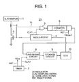
- FIG. 1 is a block diagram showing a functional structure of a control device for a vehicle alternator according to a first embodiment of the present invention.
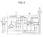
- FIG. 2 is a circuit diagram schematically showing the control device for the vehicle alternator according to the first embodiment of the present invention and peripheral related components.
- FIG. 3 is a flowchart showing an algorithm of processes according to the first embodiment of the present invention.
- FIG. 4 is a timing chart showing sampling operation according to the first embodiment of the present invention, showing a sampling cycle TSa in a case where field switch cycles Tsw are constant.
- FIG. 5 is a timing chart showing sampling operation according to the first embodiment of the present invention, showing a sampling cycle TSb in a case where field switch cycles Tsw1 to Tsw4 are not constant.
- FIG. 6 is a block diagram showing a functional structure of a control device for a vehicle alternator according to a second embodiment of the present invention, showing a case where a signal on a side of a collector terminal of a power transistor is used as an ON/OFF signal indicating a field switch ratio.
- Hereinafter, a control device for a vehicle alternator according to a first embodiment of the present invention will be described with reference to FIGS. 1 to 5.
- In FIG. 1, a
field coil 2 provided at a rotor of analternator 1 is connected to apower transistor 3 functioning as a field switching element. - A gate logic signal GL (control signal) from a
regulator IC 4 is inputted to a gate terminal of thepower transistor 3. Thepower transistor 3 is placed in the ON state or in the OFF state by the control signal for performing duty control of the field current flowing through thefield coil 2. - The
regulator IC 4 together with anAND gate 5, acounter 6, atimer 7, anaveraging circuit 8, and astorage circuit 9 make up aregulator 20 for controlling a power generation voltage of thealternator 1. - The
regulator 20 is included in the alternator 1 (see FIG. 2). - The
AND gate 5, thecounter 6, thetimer 7, theaveraging circuit 8, and thestorage circuit 9 may be incorporated as a part of functions in theregulator IC 4. - The
AND gate 5 performs a logical AND operation on a clock signal CLK1 of thecounter 6 and the gate logic signal GL, and inputs to the counter 6 a logical product signal having a clock number corresponding to an H level segment of the gate logic signal GL. - Each time the logical product signal in response to the clock signal CLK1 is inputted to the
counter 6, thecounter 6 increments its counter value, and inputs the counter value corresponding to the duty ratio of the gate logic signal GL to theaveraging circuit 8. - Further, each time an average value during sampling time arbitrarily set in advance is calculated, the
counter 6 resets (clears) the counter value to 0 by a reset signal RST from thetimer 7. - The
timer 7 generates the reset signal RST at the time when a sampling signal CLK2 corresponding to the sampling time is generated. The sampling time (generation cycle of the sampling signal CLK2) is arbitrarily set in advance depending on the target specification. - Each time the sampling signal CLK2 is inputted to the
averaging circuit 8, theaveraging circuit 8 performs an averaging process of the counter value of thecounter 6, and stores the average value in thestorage circuit 9. - An
ECU 10 reads the average value stored in thestorage circuit 9, and inputs the average value to the regulator IC 4 as feedback information. In response to the input of the feedback information, theregulator IC 4 generates a control signal to thepower transistor 3 for controlling the power generation voltage of thealternator 1. - In FIG. 2, the
alternator 1 includes a stator having a three-phase wining and a three-phase rectifier circuit, a rotor having thefield coil 2, and theregulator 20 including thepower transistor 3 and theregulator IC 4. - The
regulator 20 is connected to a stator circuit through output terminals B, E and a control terminal P of thealternator 1, connected to thefield coil 2 through a field terminal F there of, and connected to theECU 10 through a control terminal C there of. - A
battery 20 and theelectrical load 22 mounted in the vehicle are connected between the output terminals B and E of thealternator 1. - In FIGS. 1 and 2, the
regulator IC 4 monitors the ON/OFF signal of thepower transistor 3. - At this time, as shown in FIG. 1, the gate logic signal GL of the
power transistor 3 is used as a DF signal for monitoring. - In the
regulator 20, the logic AND operation of the clock signal CLK1 of thecounter 6 and the gate logic signal GL is performed to input the clock signal CLK1 to thecounter 6 while the gate logic signal GL is in the ON period, and the averaging process of the counter value is performed in each predetermined sampling time (in the cycle of the sampling signal CLK2). - Next, with reference to FIGS. 3 to 5, the averaging process according to the first embodiment of the present invention shown in FIGS. 1 and 2 will be described specifically.
- The process routine in FIG. 3 is performed by the
regulator IC 4 in theregulator 20 in association with the respectiveconstitutive elements 5 to 9. - In FIG. 3, firstly, it is determined whether the gate logic signal GL indicating the ON/OFF state of the
power transistor 3 is at the H level (ON state) (step S1). - In step S1, if the gate logic signal GL is at the H level (i. e. YES), then, it is determined whether the clock signal CLK1 from the
regulator IC 4 is inputted or not (step S2). - In step S2, if it is determined that the clock signal CLK1 is inputted (i.e., YES), the
counter 6 counts up to increment the counter value (step S3). Then, the routine proceeds to step S4. - In step S1, if it is determined that the gate logic signal GL is at the L level (OFF state) (i.e., NO), or in step S2, if it is determined that the clock signal CLK2 is not inputted (i.e., NO), the increment process of the counter 6 (step S3) is not performed, and the routine proceeds to step S4.
- Next, it is determined whether predetermined sampling time has elapsed or not is determined based on whether the sampling signal CLK2 from the
timer 7 is inputted or not (step S4). - In step S4, if it is determined that the
sampling signal CLK 2 is inputted (sampling time has passed) (i.e., YES), theaveraging circuit 8 performs the averaging process using the sampled counter value and the sampling cycle (step S5). - Then, the average value (average field switch ratio) calculated by the averaging
circuit 8 is stored in the storage circuit 9 (step S6), and the counter value of thecounter 6 is cleared to 0 by the reset signal RST (step S7). Then, the process routine in FIG. 3 is finished, and the routine returns to step S1. - Thereafter, the processes in steps S1 to S7 are repeated.
- The average field switch ratio in the
storage circuit 9 is transmitted to theECU 10 in response to an output instruction performed at an arbitrary time. - In step S4, if it is determined that the
sampling signal CLK 2 is not inputted (sampling time has not passed) (i.e., NO), the process routine in FIG. 3 is finished, and the routine returns to step S1 without performing the processes in steps S5 to S7. - As described above, the sampling time is arbitrarily set in advance by a user (designer).
- For example, as shown in FIG. 4, when field switch cycles Tsw of the
power transistor 3 are always constant, the generation cycle of the sampling signal CLK2 is set such that sampling of the counter value is performed in each cycle which is N times as long as the field switch cycle Tsw (Tsw x N). - The integral number N can be set to an arbitrary number which is 2 or greater. When the integral number N is a significantly large number, the responsiveness until the averaging information can be obtained is lowered. Therefore, it is desirable that the value of the integral number N is set in a practical range according to the required specification of the overall system.
- As shown in FIG. 3, when the sampling cycle TSa (= Tsw x N) is set, an average field switch ratio Ka is a value (To/TSa) calculated by dividing the ON time To of the gate logic signal GL (corresponding to the counter value) by the sampling cycle TSa.
- As shown in FIG. 5, when the field switch cycles Tsw1, Tsw2, Tsw3, and Tsw4 vary in each control timing, the generation cycle of the sampling signal CLK2 is set such that the sampling cycle TSb is much longer than the longest field switch cycle Tsw3.
- In this case, the average field switch ratio Kb obtained in the averaging process (step S5) is "To/Tsb".
- In this manner, it is possible to obtain information of the stable field switch ratio by the averaging process.
- The averaging process may be performed by a divider circuit. However, in order to avoid increase in circuit size, for example, a known technique such as a bit shift is used for the counter.
- As described above, an ON time To of the gate logic signal GL in the arbitrary sampling time is measured by the
counter 6 for averaging the ON time To to calculate the average field switch ratio. Thus, it is possible to obtain the stable field switch ratio as ON ratio information of the DF signal. In this case, the circuit size is not large. - Further, when the
ECU 10 monitors the field switch ratio, disturbance by irregular signals before and after the monitoring does not occur. Therefore, it is possible to obtain the DF signal which is stable to some extent, and realize the stability in the engine control by the ECU. - Accordingly, it is possible to reduce the circuit size, and stabilize the engine control.
- Since it is possible to select the sampling time and the algorithm for the averaging process arbitrarily to some extent, the circuit is optimized easily, and cost reduction is achieved.
- Further, since all the processes are performed on the control side of the alternator (on the side of the regulator 20), the stable signals are supplied to various control devices without selecting the specification of the
ECU 10 mounted in the vehicle. - Further, the circuit is configured by the functions in the
regulator IC 4 without requiring any complicated circuits such as a divider circuit or a delay circuit, the circuit size is reduced significantly. - In the first embodiment of the present invention, the gate logic signal GL of the
power transistor 3 is used as the ON/OFF signal indicating the field switch ratio. Alternatively, a signal on a side of a collector terminal (on a side of a drain terminal) of thepower transistor 3 may be used. - FIG. 6 is a block diagram showing a control device for a vehicle alternator according to a second embodiment of the present invention in which a field logic signal FL on the side of the collector terminal of the
power transistor 3 is used as a monitor signal. - In FIG. 6, the constituent elements that are identical to those shown in FIG. 1 are labeled with the same reference numeral or the same reference numeral with suffix "A", and description thereof will be omitted.
- In this case, since the logic of the monitor signal inputted to the
regulator 20A has a reverse polarity, theregulator 20A has anOR gate 5A instead of the ANDgate 5 as described above with reference to FIG. 1. - The
OR gate 5A receives the field logic signal FL on the side of the collector terminal of thepower transistor 3, and performs an OR operation to input the signal having the reverse polarity as a logical sum signal to thecounter 6. - That is, in the OFF period of the field logic signal FL (corresponding to the ON period of the gate logic signal GL), the
OR gate 5A passes the OFF pulse of the clock signal CLK1 such that thecounter 6 counts up. - Thereafter, the same processes as described above are performed. Thus, the same effects and advantages can be achieved also in this case.
Claims (7)
- A control device for a vehicle alternator, comprising:an alternator connected to a battery mounted in a vehicle;a regulator including a regulator IC for adjusting the power generation voltage of the alternator; andan ECU connected to the regulator,wherein an average value obtained by performing an averaging process on ON time of a DF signal measured during predetermined sampling time is used as ON ratio information of the DF signal inputted from the regulator to the ECU.
- A control device for a vehicle alternator according to claim 1, wherein the regulator IC comprises:a power transistor for performing ON/OFF control of a field current of the alternator;a counter for measuring the ON time of the DF signal as a counter value, the counter value being cleared to 0 by a reset signal;a timer for generating a sampling signal and the reset signal in each sampling time;an averaging circuit for performing an averaging process on the counter value in response to the sampling signal; anda storage circuit for storing the average value calculated by the averaging circuit.
- A control device for a vehicle alternator according to claim 1 or 2, wherein the sampling time is set to an arbitrary value in advance.
- A control device for a vehicle alternator according to claim 2, wherein the DF signal is a gate logic signal of the power transistor.
- A control device for a vehicle alternator according to claim 4, wherein the regulator IC includes an AND gates, and the AND gate inputs a clock signal to the counter during an ON period of the gate logic signal.
- A control device for a vehicle alternator according to claim 2, wherein the FD signal is a field logic signal on a side of a collector terminal of the power transistor.
- A control device for a vehicle alternator according to claim 6, wherein the regulator IS includes an OR gate, and the OR gate inputs a clock signal to the counter during an OFF period of the field logic signal.
Applications Claiming Priority (1)
| Application Number | Priority Date | Filing Date | Title |
|---|---|---|---|
| PCT/JP2003/012260 WO2005031964A1 (en) | 2003-09-25 | 2003-09-25 | Controller of alternator for vehicle |
Publications (3)
| Publication Number | Publication Date |
|---|---|
| EP1667317A1 true EP1667317A1 (en) | 2006-06-07 |
| EP1667317A4 EP1667317A4 (en) | 2014-05-14 |
| EP1667317B1 EP1667317B1 (en) | 2015-07-01 |
Family
ID=34385861
Family Applications (1)
| Application Number | Title | Priority Date | Filing Date |
|---|---|---|---|
| EP03818785.2A Expired - Lifetime EP1667317B1 (en) | 2003-09-25 | 2003-09-25 | Controller of alternator for vehicle |
Country Status (5)
| Country | Link |
|---|---|
| US (1) | US7161328B2 (en) |
| EP (1) | EP1667317B1 (en) |
| JP (1) | JP4410194B2 (en) |
| CN (1) | CN100373766C (en) |
| WO (1) | WO2005031964A1 (en) |
Families Citing this family (5)
| Publication number | Priority date | Publication date | Assignee | Title |
|---|---|---|---|---|
| JP4017637B2 (en) * | 2005-04-21 | 2007-12-05 | 三菱電機株式会社 | Control device for vehicle generator |
| JP4080493B2 (en) * | 2005-04-21 | 2008-04-23 | 三菱電機株式会社 | Control device for vehicle generator |
| JP4596185B2 (en) | 2007-08-29 | 2010-12-08 | 株式会社デンソー | Voltage control device for vehicle |
| CN101577445B (en) * | 2008-05-07 | 2012-07-04 | 环旭电子股份有限公司 | Adjustable voltage regulation circuit and operating method thereof |
| DE102010029507A1 (en) * | 2010-05-31 | 2011-12-01 | Robert Bosch Gmbh | Method and device for generating discrete values of a current by means of an inductance for limiting an excitation current for a motor vehicle generator |
Family Cites Families (18)
| Publication number | Priority date | Publication date | Assignee | Title |
|---|---|---|---|---|
| JPH0810999B2 (en) * | 1983-06-01 | 1996-01-31 | 本田技研工業株式会社 | Control device for vehicle generator |
| US5270575A (en) * | 1989-11-30 | 1993-12-14 | Mitsubishi Jidosha Kogyo Kabushiki Kaisha | Device for controlling change in idling |
| JPH05304473A (en) | 1992-04-24 | 1993-11-16 | Yokogawa Electric Corp | Pwm system a/d converter |
| FR2701609B1 (en) * | 1993-02-12 | 1995-05-12 | Valeo Equip Electr Moteur | Regulator circuit with progressive excitation for charging a battery by an alternator. |
| JP3592767B2 (en) * | 1994-11-09 | 2004-11-24 | 三菱電機株式会社 | Engine control device |
| JP3531277B2 (en) * | 1995-04-24 | 2004-05-24 | 株式会社デンソー | AC generator for vehicle and control method thereof |
| US5731689A (en) * | 1995-06-06 | 1998-03-24 | Nippondenso Co., Ltd. | Control system for A.C. generator |
| JPH10327541A (en) * | 1997-05-26 | 1998-12-08 | Mitsubishi Electric Corp | Control device for vehicle generator |
| KR100376923B1 (en) * | 1998-11-18 | 2003-03-26 | 미쓰비시덴키 가부시키가이샤 | Controller of ac generator for vehicle |
| US6184661B1 (en) * | 1999-06-22 | 2001-02-06 | C. E. Niehoff & Co. | Regulator with alternator output current and input drive power control |
| JP3556871B2 (en) | 1999-11-11 | 2004-08-25 | 三菱電機株式会社 | Alternator control device |
| JP4144154B2 (en) | 2000-03-13 | 2008-09-03 | 株式会社デンソー | VEHICLE POWER GENERATION CONTROL DEVICE HAVING TRANSMISSION / RECEIVER |
| JP3513074B2 (en) * | 2000-03-29 | 2004-03-31 | 株式会社オートネットワーク技術研究所 | Electric power supply system using vehicles |
| JP4207402B2 (en) * | 2000-10-13 | 2009-01-14 | 株式会社デンソー | Voltage control device |
| JP2002156393A (en) | 2000-11-22 | 2002-05-31 | Nec Corp | Battery voltage measurement circuit |
| JP4438260B2 (en) * | 2001-08-30 | 2010-03-24 | 株式会社デンソー | Vehicle power generation control device |
| JP2004173482A (en) * | 2002-11-05 | 2004-06-17 | Kokusan Denki Co Ltd | Power generator with magnet generator |
| US6819011B2 (en) * | 2002-11-14 | 2004-11-16 | Fyre Storm, Inc. | Switching power converter controller with watchdog timer |
-
2003
- 2003-09-25 WO PCT/JP2003/012260 patent/WO2005031964A1/en not_active Ceased
- 2003-09-25 CN CNB038197170A patent/CN100373766C/en not_active Expired - Fee Related
- 2003-09-25 US US10/529,237 patent/US7161328B2/en not_active Expired - Lifetime
- 2003-09-25 JP JP2005509182A patent/JP4410194B2/en not_active Expired - Lifetime
- 2003-09-25 EP EP03818785.2A patent/EP1667317B1/en not_active Expired - Lifetime
Also Published As
| Publication number | Publication date |
|---|---|
| EP1667317A4 (en) | 2014-05-14 |
| US7161328B2 (en) | 2007-01-09 |
| JPWO2005031964A1 (en) | 2006-12-07 |
| CN1714498A (en) | 2005-12-28 |
| US20060017420A1 (en) | 2006-01-26 |
| EP1667317B1 (en) | 2015-07-01 |
| JP4410194B2 (en) | 2010-02-03 |
| WO2005031964A1 (en) | 2005-04-07 |
| CN100373766C (en) | 2008-03-05 |
Similar Documents
| Publication | Publication Date | Title |
|---|---|---|
| US8183846B2 (en) | Method and apparatus for controlling a DC/DC converter | |
| JP3467679B2 (en) | DC / DC converter | |
| CN202663300U (en) | Switching regulator and control circuit thereof | |
| US5905364A (en) | Rapid battery charger with charge controlling capability depending on overvoltage of the battery | |
| US8102687B2 (en) | Control apparatus for controlling power conversion apparatus | |
| EP2200163B1 (en) | Method for predictive PWM current control | |
| JP6772980B2 (en) | In-vehicle signal generation circuit and in-vehicle power supply | |
| US9285400B2 (en) | Method for determining current in a polyphase machine | |
| US10530252B2 (en) | Pulse-frequency control circuit, microcomputer, DC-to-DC converter, and pulse-frequency control method | |
| US11121630B2 (en) | In-vehicle DC-DC converter | |
| US20130127428A1 (en) | Dc-dc converter | |
| JP6015370B2 (en) | Switching power supply | |
| US20100270988A1 (en) | pulse time detector, a controller for a switched mode power supply, and a switched mode power supply including such a controller | |
| EP1667317B1 (en) | Controller of alternator for vehicle | |
| US20090085544A1 (en) | Current regulator and method for regulating current | |
| US8120339B2 (en) | Switching power supply with switching circuits | |
| JP4017637B2 (en) | Control device for vehicle generator | |
| EP3513487A1 (en) | Dc-dc converters | |
| JP2010130774A (en) | Power system | |
| US8129857B2 (en) | Semiconductor circuit | |
| KR100673190B1 (en) | Controller of vehicle alternator | |
| CN114244109B (en) | Control circuit and method for DC-DC converter and DC-DC converter | |
| US7038428B1 (en) | Control apparatus for automotive generator | |
| US7498790B2 (en) | Switching regulator frequency control | |
| EP2768114B1 (en) | Charging device |
Legal Events
| Date | Code | Title | Description |
|---|---|---|---|
| PUAI | Public reference made under article 153(3) epc to a published international application that has entered the european phase |
Free format text: ORIGINAL CODE: 0009012 |
|
| 17P | Request for examination filed |
Effective date: 20050407 |
|
| AK | Designated contracting states |
Kind code of ref document: A1 Designated state(s): DE FR GB |
|
| RBV | Designated contracting states (corrected) |
Designated state(s): DE FR GB |
|
| A4 | Supplementary search report drawn up and despatched |
Effective date: 20140416 |
|
| RIC1 | Information provided on ipc code assigned before grant |
Ipc: H02P 9/30 20060101ALI20140410BHEP Ipc: H02J 7/14 20060101ALI20140410BHEP Ipc: H02P 9/48 20060101ALI20140410BHEP Ipc: H02P 9/04 20060101AFI20140410BHEP |
|
| 17Q | First examination report despatched |
Effective date: 20140801 |
|
| GRAP | Despatch of communication of intention to grant a patent |
Free format text: ORIGINAL CODE: EPIDOSNIGR1 |
|
| INTG | Intention to grant announced |
Effective date: 20150130 |
|
| GRAS | Grant fee paid |
Free format text: ORIGINAL CODE: EPIDOSNIGR3 |
|
| GRAA | (expected) grant |
Free format text: ORIGINAL CODE: 0009210 |
|
| AK | Designated contracting states |
Kind code of ref document: B1 Designated state(s): DE FR GB |
|
| REG | Reference to a national code |
Ref country code: GB Ref legal event code: FG4D |
|
| REG | Reference to a national code |
Ref country code: DE Ref legal event code: R096 Ref document number: 60347775 Country of ref document: DE |
|
| REG | Reference to a national code |
Ref country code: DE Ref legal event code: R097 Ref document number: 60347775 Country of ref document: DE |
|
| PLBE | No opposition filed within time limit |
Free format text: ORIGINAL CODE: 0009261 |
|
| STAA | Information on the status of an ep patent application or granted ep patent |
Free format text: STATUS: NO OPPOSITION FILED WITHIN TIME LIMIT |
|
| 26N | No opposition filed |
Effective date: 20160404 |
|
| REG | Reference to a national code |
Ref country code: FR Ref legal event code: PLFP Year of fee payment: 14 |
|
| REG | Reference to a national code |
Ref country code: FR Ref legal event code: PLFP Year of fee payment: 15 |
|
| REG | Reference to a national code |
Ref country code: FR Ref legal event code: PLFP Year of fee payment: 16 |
|
| PGFP | Annual fee paid to national office [announced via postgrant information from national office to epo] |
Ref country code: GB Payment date: 20200916 Year of fee payment: 18 Ref country code: FR Payment date: 20200812 Year of fee payment: 18 Ref country code: DE Payment date: 20200916 Year of fee payment: 18 |
|
| REG | Reference to a national code |
Ref country code: DE Ref legal event code: R119 Ref document number: 60347775 Country of ref document: DE |
|
| GBPC | Gb: european patent ceased through non-payment of renewal fee |
Effective date: 20210925 |
|
| PG25 | Lapsed in a contracting state [announced via postgrant information from national office to epo] |
Ref country code: GB Free format text: LAPSE BECAUSE OF NON-PAYMENT OF DUE FEES Effective date: 20210925 Ref country code: FR Free format text: LAPSE BECAUSE OF NON-PAYMENT OF DUE FEES Effective date: 20210930 Ref country code: DE Free format text: LAPSE BECAUSE OF NON-PAYMENT OF DUE FEES Effective date: 20220401 |