EP1667270A1 - Gasverteilerplatte für eine Hochtemperatur-Brennstoffzelle - Google Patents
Gasverteilerplatte für eine Hochtemperatur-Brennstoffzelle Download PDFInfo
- Publication number
- EP1667270A1 EP1667270A1 EP05024620A EP05024620A EP1667270A1 EP 1667270 A1 EP1667270 A1 EP 1667270A1 EP 05024620 A EP05024620 A EP 05024620A EP 05024620 A EP05024620 A EP 05024620A EP 1667270 A1 EP1667270 A1 EP 1667270A1
- Authority
- EP
- European Patent Office
- Prior art keywords
- fuel cell
- gas distribution
- temperature fuel
- distribution plate
- channels
- Prior art date
- Legal status (The legal status is an assumption and is not a legal conclusion. Google has not performed a legal analysis and makes no representation as to the accuracy of the status listed.)
- Granted
Links
Images


Classifications
-
- H—ELECTRICITY
- H01—ELECTRIC ELEMENTS
- H01M—PROCESSES OR MEANS, e.g. BATTERIES, FOR THE DIRECT CONVERSION OF CHEMICAL ENERGY INTO ELECTRICAL ENERGY
- H01M8/00—Fuel cells; Manufacture thereof
- H01M8/02—Details
- H01M8/0202—Collectors; Separators, e.g. bipolar separators; Interconnectors
- H01M8/0258—Collectors; Separators, e.g. bipolar separators; Interconnectors characterised by the configuration of channels, e.g. by the flow field of the reactant or coolant
- H01M8/026—Collectors; Separators, e.g. bipolar separators; Interconnectors characterised by the configuration of channels, e.g. by the flow field of the reactant or coolant characterised by grooves, e.g. their pitch or depth
-
- H—ELECTRICITY
- H01—ELECTRIC ELEMENTS
- H01M—PROCESSES OR MEANS, e.g. BATTERIES, FOR THE DIRECT CONVERSION OF CHEMICAL ENERGY INTO ELECTRICAL ENERGY
- H01M8/00—Fuel cells; Manufacture thereof
- H01M8/10—Fuel cells with solid electrolytes
- H01M8/1007—Fuel cells with solid electrolytes with both reactants being gaseous or vaporised
-
- H—ELECTRICITY
- H01—ELECTRIC ELEMENTS
- H01M—PROCESSES OR MEANS, e.g. BATTERIES, FOR THE DIRECT CONVERSION OF CHEMICAL ENERGY INTO ELECTRICAL ENERGY
- H01M8/00—Fuel cells; Manufacture thereof
- H01M8/10—Fuel cells with solid electrolytes
- H01M8/12—Fuel cells with solid electrolytes operating at high temperature, e.g. with stabilised ZrO2 electrolyte
- H01M8/1231—Fuel cells with solid electrolytes operating at high temperature, e.g. with stabilised ZrO2 electrolyte with both reactants being gaseous or vaporised
-
- Y—GENERAL TAGGING OF NEW TECHNOLOGICAL DEVELOPMENTS; GENERAL TAGGING OF CROSS-SECTIONAL TECHNOLOGIES SPANNING OVER SEVERAL SECTIONS OF THE IPC; TECHNICAL SUBJECTS COVERED BY FORMER USPC CROSS-REFERENCE ART COLLECTIONS [XRACs] AND DIGESTS
- Y02—TECHNOLOGIES OR APPLICATIONS FOR MITIGATION OR ADAPTATION AGAINST CLIMATE CHANGE
- Y02E—REDUCTION OF GREENHOUSE GAS [GHG] EMISSIONS, RELATED TO ENERGY GENERATION, TRANSMISSION OR DISTRIBUTION
- Y02E60/00—Enabling technologies; Technologies with a potential or indirect contribution to GHG emissions mitigation
- Y02E60/30—Hydrogen technology
- Y02E60/50—Fuel cells
Definitions
- the invention relates to a high-temperature fuel cell, in particular a gas distributor plate on the cathode side of such a fuel cell.
- the cathode gas When operating high-temperature fuel cells, on the one hand, the cathode gas should be distributed evenly over the cathode and, on the other hand, at the same time the current should be conducted from the cathode to the interconnector. This is done regularly via so-called interconnectors.
- the electrical contacting and gas distribution of the interconnectors via channels, which are incorporated mechanically into the interconnector, or by thin sheets, which are produced via a stamping process.
- stainless steel mesh or fabric can be inserted between electrodes and planar interconnectors.
- the interconnectors used so far have some disadvantages.
- the mechanical processing of a solid interconnector is usually time-consuming and therefore cost-intensive.
- the embossing of thin sheets in contrast, while inexpensive, but has the disadvantage that the mechanical stiffness of the thin sheets at the high operating temperature is low and the ratio of channel width to channel depth by the deformation behavior of the sheet is adversely limited.
- the stability of the thin wires due to corrosion is no longer certain after a few hours of use.
- Object of this invention is to provide a device for homogeneous gas distribution on the cathode side of a high-temperature fuel cell available, which is both inexpensive to produce, and yet has the required mechanical stability and corrosion resistance at the operating temperatures.
- the invention relates to a gas distribution plate, which is easy to manufacture as an insert, is mechanically stable and has wall thicknesses that make it sufficiently corrosion resistant for use in a high temperature fuel cell.
- the gas distributor plate according to the invention can advantageously be produced from a planar sheet with a wall thickness of up to 2 mm, in which a channel structure of any web or channel width is realized, for example by punching or laser or water jet cutting.
- Suitable materials for the component according to the invention are the customary interconnector materials, such as, for example, ferritic chromium steels.
- a minimum wall thickness of 0.5 mm should not be undercut regularly to ensure stability and corrosion resistance.
- the channel or channels do not run completely over the entire sheet width, but it remains at the edge of a kind of frame.
- transverse webs which ensure the stability of the gas distribution plate component.
- Decisive for the component according to the invention is now that at least one of these transverse webs is bevelled in the region of the recesses, so that the cathode gas can flow into and out of the channel structure.
- the channels on both sides in the region of the transverse webs chamfers, so that the cathode gas without much resistance in the distributor and can emerge again.
- the gas distribution plate itself can be soldered or welded for better contacting, for example, to a smooth interconnector plate or contacted by a ceramic contact paste and by simply pressing.
- the gas distributor plate consists of a chromium evaporating material
- it can be coated with a ceramic protective layer, for example by wet powder spraying or dip coating, in order to regularly prevent the disadvantageous evaporation of chromium from the chrome oxide covering layer of the component.
- this gas distributor plate according to the invention thus fulfills the requirement of being easy to produce, mechanically stable and sufficiently resistant to corrosion.
- a typical embodiment of a gas distribution plate has the external dimensions 100 x 100 x 1 mm.
- the plate is made of a ferritic chrome steel.
- the channel structures were stamped.
- the channels and the webs each have a width of 1.5 mm.
- the channels At the lateral transverse webs, the channels each have a bevel of 20 °.
Landscapes
- Life Sciences & Earth Sciences (AREA)
- Engineering & Computer Science (AREA)
- Manufacturing & Machinery (AREA)
- Sustainable Development (AREA)
- Sustainable Energy (AREA)
- Chemical & Material Sciences (AREA)
- Chemical Kinetics & Catalysis (AREA)
- Electrochemistry (AREA)
- General Chemical & Material Sciences (AREA)
- Fuel Cell (AREA)
Abstract
Description
- Die Erfindung betrifft eine Hochtemperatur-Brennstoffzelle, insbesondere eine Gasverteilerplatte auf der Kathodenseite einer solchen Brennstoffzelle.
- Beim Betrieb von Hochtemperatur-Brennstoffzellen sollte einerseits das Kathodengas gleichmäßig über der Kathode verteilt werden und andererseits gleichzeitig der Strom von der Kathode zum Interkonnektor geleitet werden. Dies geschieht regelmäßig über so genannten Interkonnektoren.
- Üblicherweise erfolgt die elektrische Kontaktierung und Gasverteilung der Interkonnektoren über Kanäle, die mechanisch in den Interkonnektor eingearbeitet werden, oder aber durch dünne Bleche, die über einen Prägevorgang hergestellt werden. Alternativ werden auch Netze oder Gewebe aus Edelstahl zwischen Elektroden und planaren Interkonnektoren eingelegt.
- Die bislang eingesetzten Interkonnektoren weisen jedoch einige Nachteile auf. So ist die mechanische Bearbeitung eines massiven Interkonnektors in der Regel zeit- und damit kostenintensiv. Das Prägen von dünnen Blechen ist demgegenüber zwar kostengünstig, hat allerdings den Nachteil, dass die mechanische Steifigkeit der dünnen Bleche bei der hohen Betriebstemperatur gering ist und das Verhältnis von Kanalbreite zu Kanaltiefe durch das Verformungsverhalten des Bleches nachteilig begrenzt ist. Beim Einsatz von Netzen und Geweben ist die Stabilität der dünnen Drähte aufgrund von Korrosion nach einigen Betriebsstunden nicht mehr sicher gegeben.
- Aufgabe dieser Erfindung ist es, eine Vorrichtung zur homogenen Gasverteilung auf der Kathodenseite eine Hochtemperatur-Brennstoffzelle zur Verfügung zu stellen, die einerseits kostengünstig herstellbar ist, und dennoch die erforderliche mechanische Stabilität und Korrosionsfestigkeit bei den Einsatztemperaturen aufweist.
- Die Aufgabe der Erfindung wird gelöst durch eine Gasverteilerplatte mit der Gesamtheit an Merkmalen gemäß Hauptanspruch. Weitere vorteilhafte Ausführungen finden sich in den davon abhängigen Ansprüchen wieder.
- Die Erfindung betrifft eine Gasverteilerplatte, welche als ein Einlegeteil einfach herzustellen ist, mechanisch stabil ist und Wandstärken aufweist, die es für einen Einsatz in einer Hochtemperatur-Brennstoffzelle ausreichend korrosionsstabil machen.
- Die erfindungsgemäße Gasverteilerplatte kann vorteilhaft aus einem planaren Blech mit einer Wandstärke bis 2 mm hergestellt werden, in dem eine Kanalstruktur beliebiger Steg bzw. Kanalbreite zum Beispiel durch Stanzen oder Laser- oder Wasserstrahlschneiden realisiert wird.
- Als geeignete Materialien für das erfindungsgemäße Bauteil sind die üblichen Interkonnektorwerkstoffe, wie beispielsweise ferritische Chromstähle zu nennen. Eine minimale Wandstärke von 0,5 mm sollte regelmäßig nicht unterschritten werden, um die Stabilität und Korrosionsbeständigkeit sicherzustellen.
- Der bzw. die Kanäle verlaufen jedoch nicht komplett über die gesamte Blechbreite, sondern es verbleibt am Rand eine Art Rahmen. Für parallel verlaufende Kanäle ergeben sich somit am Anfang und am Ende Verbindungen durch so genannte Querstege, die für die Stabilität des Gasverteilerplatte-Bauteils sorgen. Entscheidend für das erfindungsgemäße Bauteil ist nun, dass wenigstens einer dieser Querstege im Bereich der Aussparungen angeschrägt ist, so dass das Kathodengas in die Kanalstruktur ein- und ausströmen kann. Durch die Ausführung der Schräge kann vorteilhaft der Einströmwiderstand und damit die Strömungsgleichverteilung beeinflusst werden.
- Bei einer direkten parallelen Strömungsführung weisen die Kanäle an beiden Seiten im Bereich der Querstege Anschrägungen auf, damit das Kathodengas ohne größeren Widerstand in den Verteiler ein- und wieder austreten kann.
- Es ist im Rahmen der Erfindung aber auch möglich, die Kanäle in Form einfacher Mäanderstrukturen auszubilden. Es muss nur sichergestellt sein, dass durch die Querstege die mechanische Stabilität der Verteilerstruktur in ausreichendem Maße sichergestellt werden kann.
- Die Gasverteilerplatte selbst kann zur besseren Kontaktierung beispielsweise an eine glatte Interkonnektorplatte angelötet oder angeschweißt werden oder auch durch eine keramische Kontaktpaste und durch einfaches Andrücken kontaktiert werden.
- Sofern die Gasverteilerplatte aus einem chromabdampfenden Material besteht, kann sie beispielsweise durch Nasspulverspritzen oder Tauchen (Dip-Coating) mit einer keramischen Schutzschicht überzogen werden, um das nachteilige Verdampfen von Chrom aus der Chromoxid-Deckschicht des Bauteils regelmäßig zu verhindern.
- Damit erfüllt diese erfindungsgemäße Gasverteilerplatte insbesondere die Anforderung einfach herstellbar, mechanisch stabil und ausreichend korrosionsstabil zu sein.
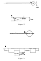
- Nachfolgend wird der Gegenstand der Erfindung anhand von Figuren und einem Ausführungsbeispiel näher erläutert, ohne dass der Gegenstand der Erfindung dadurch beschränkt wird. Es zeigen:
- Figur 1:
- Aufsicht auf eine Ausgestaltung der erfindungsgemäßen Gasverteilerplatte.
- Figur 2:
- Schnittzeichnung mit Kanalstruktur.
- Figur 3:
- Schnittzeichnung einer Anschrägung eines Kanals im Bereich eines Querstegs.
- Ein typisches Ausführungsbeispiel einer Gasverteilerplatte weist die Außenmaße 100 x 100 x 1 mm auf. Die Platte ist aus einem ferritischen Chromstahl gefertigt. Die Kanalstrukturen wurden eingestanzt. Die Kanäle und die Stege weisen jeweils eine Breite von 1,5 mm auf. An den seitlichen Querstegen weisen die Kanäle jeweils eine Abschrägung von 20 ° auf.
Claims (5)
- Gasverteilerplatte für eine Hochtemperatur-Brennstoffzelle umfassend ein planares Blech mit Kanalstrukturen, wobei das Blech einen umlaufenden Rahmen aufweist, und die Kanäle am Anfang und am Ende jeweils eine Abschrägung aufweisen.
- Gasverteilerplatte nach vorhergehendem Anspruch 1, bei dem die Kanalstrukturen parallel verlaufen.
- Gasverteilerplatte nach einem der vorhergehenden Ansprüche 1 bis 2, bei dem die Kanalstrukturen jeweils eine Breite von 0,5 bis 2 mm aufweisen, insbesondere eine Breite von 1 bis 1,5 mm.
- Gasverteilerplatte nach einem der vorhergehenden Ansprüche 1 bis 3 mit einer Wandstärke von 0,5 bis 2 mm.
- Gasverteilerplatte nach einem der vorhergehenden Ansprüche 1 bis 4 bei dem die Kanäle der Kanalstrukturen identische Geometrien aufweisen.
Applications Claiming Priority (1)
| Application Number | Priority Date | Filing Date | Title |
|---|---|---|---|
| DE102004056422A DE102004056422A1 (de) | 2004-11-23 | 2004-11-23 | Gasverteilerplatte für eine Hochtemperatur-Brennstoffzelle |
Publications (2)
| Publication Number | Publication Date |
|---|---|
| EP1667270A1 true EP1667270A1 (de) | 2006-06-07 |
| EP1667270B1 EP1667270B1 (de) | 2014-07-23 |
Family
ID=36064239
Family Applications (1)
| Application Number | Title | Priority Date | Filing Date |
|---|---|---|---|
| EP05024620.6A Expired - Lifetime EP1667270B1 (de) | 2004-11-23 | 2005-11-11 | Gasverteilerplatte für eine Hochtemperatur-Brennstoffzelle |
Country Status (3)
| Country | Link |
|---|---|
| EP (1) | EP1667270B1 (de) |
| DE (1) | DE102004056422A1 (de) |
| DK (1) | DK1667270T3 (de) |
Cited By (1)
| Publication number | Priority date | Publication date | Assignee | Title |
|---|---|---|---|---|
| WO2006125775A1 (de) * | 2005-05-27 | 2006-11-30 | Basf Aktiengesellschaft | Bipolarplatte für brennstoffzellen |
Families Citing this family (1)
| Publication number | Priority date | Publication date | Assignee | Title |
|---|---|---|---|---|
| DE102010020178A1 (de) | 2010-05-11 | 2011-11-17 | Schaeffler Technologies Gmbh & Co. Kg | Verfahren zur Herstellung einer metallischen Biopolarplatte, Bipolarplatte sowie Brennstoffzellenstapel und Verfahren zu dessen Herstellung |
Citations (8)
| Publication number | Priority date | Publication date | Assignee | Title |
|---|---|---|---|---|
| US3631136A (en) | 1965-08-18 | 1971-12-28 | Ransburg Electro Coating Corp | White to light-colored detergentresistant coating composition |
| DE3812813A1 (de) * | 1988-04-16 | 1989-06-15 | Mtu Friedrichshafen Gmbh | Elektrochemisch arbeitende brennstoffzelle |
| US5496655A (en) | 1994-10-12 | 1996-03-05 | Lockheed Idaho Technologies Company | Catalytic bipolar interconnection plate for use in a fuel cell |
| US5993986A (en) | 1995-11-16 | 1999-11-30 | The Dow Chemical Company | Solide oxide fuel cell stack with composite electrodes and method for making |
| US6106967A (en) | 1999-06-14 | 2000-08-22 | Gas Research Institute | Planar solid oxide fuel cell stack with metallic foil interconnect |
| US6316136B1 (en) * | 1998-02-17 | 2001-11-13 | Sulzer Hexis Ag | Interconnector for high temperature fuel cells |
| EP1241726A2 (de) | 2001-03-06 | 2002-09-18 | Honda Giken Kogyo Kabushiki Kaisha | Brennstoffzellenanordnung mit festen Polymerelektrolyten; Brennstoffzellenstapel und Verfahren zum Betreiben der Zellenanordnung |
| EP1294038A2 (de) | 2001-09-13 | 2003-03-19 | Honda Giken Kogyo Kabushiki Kaisha | Brennstoffzellenstapel mit verbessertem Abfluss von Kondenswasser |
Family Cites Families (2)
| Publication number | Priority date | Publication date | Assignee | Title |
|---|---|---|---|---|
| EP0749171B1 (de) * | 1995-06-13 | 1999-04-21 | Sulzer Hexis AG | Hochtemperatur-Brennstoffzelle |
| DE10261482A1 (de) * | 2002-12-23 | 2004-07-01 | Basf Ag | Brennstoffzellenmodul |
-
2004
- 2004-11-23 DE DE102004056422A patent/DE102004056422A1/de not_active Withdrawn
-
2005
- 2005-11-11 DK DK05024620.6T patent/DK1667270T3/da active
- 2005-11-11 EP EP05024620.6A patent/EP1667270B1/de not_active Expired - Lifetime
Patent Citations (8)
| Publication number | Priority date | Publication date | Assignee | Title |
|---|---|---|---|---|
| US3631136A (en) | 1965-08-18 | 1971-12-28 | Ransburg Electro Coating Corp | White to light-colored detergentresistant coating composition |
| DE3812813A1 (de) * | 1988-04-16 | 1989-06-15 | Mtu Friedrichshafen Gmbh | Elektrochemisch arbeitende brennstoffzelle |
| US5496655A (en) | 1994-10-12 | 1996-03-05 | Lockheed Idaho Technologies Company | Catalytic bipolar interconnection plate for use in a fuel cell |
| US5993986A (en) | 1995-11-16 | 1999-11-30 | The Dow Chemical Company | Solide oxide fuel cell stack with composite electrodes and method for making |
| US6316136B1 (en) * | 1998-02-17 | 2001-11-13 | Sulzer Hexis Ag | Interconnector for high temperature fuel cells |
| US6106967A (en) | 1999-06-14 | 2000-08-22 | Gas Research Institute | Planar solid oxide fuel cell stack with metallic foil interconnect |
| EP1241726A2 (de) | 2001-03-06 | 2002-09-18 | Honda Giken Kogyo Kabushiki Kaisha | Brennstoffzellenanordnung mit festen Polymerelektrolyten; Brennstoffzellenstapel und Verfahren zum Betreiben der Zellenanordnung |
| EP1294038A2 (de) | 2001-09-13 | 2003-03-19 | Honda Giken Kogyo Kabushiki Kaisha | Brennstoffzellenstapel mit verbessertem Abfluss von Kondenswasser |
Cited By (1)
| Publication number | Priority date | Publication date | Assignee | Title |
|---|---|---|---|---|
| WO2006125775A1 (de) * | 2005-05-27 | 2006-11-30 | Basf Aktiengesellschaft | Bipolarplatte für brennstoffzellen |
Also Published As
| Publication number | Publication date |
|---|---|
| DE102004056422A1 (de) | 2006-05-24 |
| DK1667270T3 (da) | 2014-10-13 |
| EP1667270B1 (de) | 2014-07-23 |
Similar Documents
| Publication | Publication Date | Title |
|---|---|---|
| EP2957659B1 (de) | Gasdiffusionsschicht, PEM-Elektrolysezelle mit einer solchen Gasdiffusionsschicht sowie Elektrolyseur | |
| EP2985096A1 (de) | Gasdiffusionselektrode | |
| WO2022233386A1 (de) | Wasserelektrolysestack zum erzeugen von wasserstoff und sauerstoff aus wasser | |
| DE102017130489A1 (de) | Bipolarplatte für eine Brennstoffzelle | |
| WO2015172946A1 (de) | Bipolarplatte und schichtstruktur auf der bipolarplatte | |
| DE102018203828A1 (de) | Gasverteilerstruktur für eine Brennstoffzelle | |
| DE102004009869A1 (de) | Kontaktplatte für Brennstoffzellen | |
| DE102010002372A1 (de) | Brennstoffzellensystem mit verbesserter Kontaktierung der Elektroden | |
| DE102009005766A1 (de) | Bipolare Platte mit variablen Oberflächeneigenschaften für eine Brennstoffzelle | |
| EP1667270B1 (de) | Gasverteilerplatte für eine Hochtemperatur-Brennstoffzelle | |
| DE102018204605A1 (de) | Gasverteilerstruktur für eine Brennstoffzelle | |
| DE102017219418A1 (de) | Gasverteilerplatte zur Gasverteilung und Strömungsführung in Elektrolyseuren und Brennstoffzellen | |
| DE102023136387A1 (de) | Poröse transportlage, einheit mit einer separatorplatte und einer porösen transportlage, elektrochemische zelle sowie verfahren zur herstellung einer derartigen porösen transportlage | |
| EP1525634B1 (de) | Bipolare platte für eine brennstoffzelle | |
| EP2532799B1 (de) | Metallträger und dessen Verwendung | |
| WO2002013287A2 (de) | Elektrochemische zelle mit polymerelektrolytmembran | |
| EP4279637A1 (de) | Elektrodenplatte mit integrierter stromübertragerstruktur und elektrodenpackungseinheit | |
| DE102018200842A1 (de) | Brennstoffzellenplatte, Bipolarplatten und Brennstoffzellenaufbau | |
| DE102020203683A1 (de) | Vorrichtung zur Mediendurchführung und Verfahren zur Herstellung | |
| DE102021205800A1 (de) | Separatorplatte für einen Brennstoffzellenstapel | |
| DE102007035830A1 (de) | Bipolarplatte für eine Brennstoffzelle, insbesondere zur Anordnung zwischen zwei benachbarten Membran-Elektroden-Anordnungen in einem Brennstoffzellenstapel | |
| DE102011051440A1 (de) | Verfahren zur Herstellung eines Interkonnektors für eine Hochtemperatur-Brennstoffzelle, Interkonnektor sowie Hochtemperatur-Brennstoffzelle | |
| EP4098773A1 (de) | Gasdiffusionsschicht für eine elektrochemische zelle und elektrochemische zelle | |
| EP1516382B1 (de) | Bipolarplatte aus graphit | |
| DE676917C (de) | Zersetzereinrichtung, insbesondere zur elektrolytischen Herstellung von Wasserstoff und Sauerstoff |
Legal Events
| Date | Code | Title | Description |
|---|---|---|---|
| PUAI | Public reference made under article 153(3) epc to a published international application that has entered the european phase |
Free format text: ORIGINAL CODE: 0009012 |
|
| AK | Designated contracting states |
Kind code of ref document: A1 Designated state(s): AT BE BG CH CY CZ DE DK EE ES FI FR GB GR HU IE IS IT LI LT LU LV MC NL PL PT RO SE SI SK TR |
|
| AX | Request for extension of the european patent |
Extension state: AL BA HR MK YU |
|
| 17P | Request for examination filed |
Effective date: 20061111 |
|
| AKX | Designation fees paid |
Designated state(s): AT BE BG CH CY CZ DE DK EE ES FI FR GB GR HU IE IS IT LI LT LU LV MC NL PL PT RO SE SI SK TR |
|
| 17Q | First examination report despatched |
Effective date: 20131025 |
|
| REG | Reference to a national code |
Ref country code: DE Ref legal event code: R079 Ref document number: 502005014447 Country of ref document: DE Free format text: PREVIOUS MAIN CLASS: H01M0008100000 Ipc: H01M0008120000 |
|
| GRAP | Despatch of communication of intention to grant a patent |
Free format text: ORIGINAL CODE: EPIDOSNIGR1 |
|
| RIC1 | Information provided on ipc code assigned before grant |
Ipc: H01M 8/12 20060101AFI20140221BHEP Ipc: H01M 8/02 20060101ALI20140221BHEP Ipc: H01M 8/10 20060101ALI20140221BHEP |
|
| INTG | Intention to grant announced |
Effective date: 20140327 |
|
| GRAS | Grant fee paid |
Free format text: ORIGINAL CODE: EPIDOSNIGR3 |
|
| GRAA | (expected) grant |
Free format text: ORIGINAL CODE: 0009210 |
|
| AK | Designated contracting states |
Kind code of ref document: B1 Designated state(s): AT BE BG CH CY CZ DE DK EE ES FI FR GB GR HU IE IS IT LI LT LU LV MC NL PL PT RO SE SI SK TR |
|
| REG | Reference to a national code |
Ref country code: GB Ref legal event code: FG4D Free format text: NOT ENGLISH |
|
| REG | Reference to a national code |
Ref country code: CH Ref legal event code: EP |
|
| REG | Reference to a national code |
Ref country code: IE Ref legal event code: FG4D Free format text: LANGUAGE OF EP DOCUMENT: GERMAN |
|
| REG | Reference to a national code |
Ref country code: AT Ref legal event code: REF Ref document number: 679319 Country of ref document: AT Kind code of ref document: T Effective date: 20140815 |
|
| REG | Reference to a national code |
Ref country code: DE Ref legal event code: R096 Ref document number: 502005014447 Country of ref document: DE Effective date: 20140904 |
|
| REG | Reference to a national code |
Ref country code: DK Ref legal event code: T3 Effective date: 20141006 |
|
| REG | Reference to a national code |
Ref country code: NL Ref legal event code: VDEP Effective date: 20140723 |
|
| REG | Reference to a national code |
Ref country code: LT Ref legal event code: MG4D |
|
| PG25 | Lapsed in a contracting state [announced via postgrant information from national office to epo] |
Ref country code: LT Free format text: LAPSE BECAUSE OF FAILURE TO SUBMIT A TRANSLATION OF THE DESCRIPTION OR TO PAY THE FEE WITHIN THE PRESCRIBED TIME-LIMIT Effective date: 20140723 Ref country code: FI Free format text: LAPSE BECAUSE OF FAILURE TO SUBMIT A TRANSLATION OF THE DESCRIPTION OR TO PAY THE FEE WITHIN THE PRESCRIBED TIME-LIMIT Effective date: 20140723 Ref country code: BG Free format text: LAPSE BECAUSE OF FAILURE TO SUBMIT A TRANSLATION OF THE DESCRIPTION OR TO PAY THE FEE WITHIN THE PRESCRIBED TIME-LIMIT Effective date: 20141023 Ref country code: SE Free format text: LAPSE BECAUSE OF FAILURE TO SUBMIT A TRANSLATION OF THE DESCRIPTION OR TO PAY THE FEE WITHIN THE PRESCRIBED TIME-LIMIT Effective date: 20140723 Ref country code: ES Free format text: LAPSE BECAUSE OF FAILURE TO SUBMIT A TRANSLATION OF THE DESCRIPTION OR TO PAY THE FEE WITHIN THE PRESCRIBED TIME-LIMIT Effective date: 20140723 Ref country code: PT Free format text: LAPSE BECAUSE OF FAILURE TO SUBMIT A TRANSLATION OF THE DESCRIPTION OR TO PAY THE FEE WITHIN THE PRESCRIBED TIME-LIMIT Effective date: 20141124 Ref country code: GR Free format text: LAPSE BECAUSE OF FAILURE TO SUBMIT A TRANSLATION OF THE DESCRIPTION OR TO PAY THE FEE WITHIN THE PRESCRIBED TIME-LIMIT Effective date: 20141024 |
|
| PG25 | Lapsed in a contracting state [announced via postgrant information from national office to epo] |
Ref country code: LV Free format text: LAPSE BECAUSE OF FAILURE TO SUBMIT A TRANSLATION OF THE DESCRIPTION OR TO PAY THE FEE WITHIN THE PRESCRIBED TIME-LIMIT Effective date: 20140723 Ref country code: CY Free format text: LAPSE BECAUSE OF FAILURE TO SUBMIT A TRANSLATION OF THE DESCRIPTION OR TO PAY THE FEE WITHIN THE PRESCRIBED TIME-LIMIT Effective date: 20140723 Ref country code: IS Free format text: LAPSE BECAUSE OF FAILURE TO SUBMIT A TRANSLATION OF THE DESCRIPTION OR TO PAY THE FEE WITHIN THE PRESCRIBED TIME-LIMIT Effective date: 20141123 Ref country code: NL Free format text: LAPSE BECAUSE OF FAILURE TO SUBMIT A TRANSLATION OF THE DESCRIPTION OR TO PAY THE FEE WITHIN THE PRESCRIBED TIME-LIMIT Effective date: 20140723 Ref country code: PL Free format text: LAPSE BECAUSE OF FAILURE TO SUBMIT A TRANSLATION OF THE DESCRIPTION OR TO PAY THE FEE WITHIN THE PRESCRIBED TIME-LIMIT Effective date: 20140723 |
|
| REG | Reference to a national code |
Ref country code: DE Ref legal event code: R097 Ref document number: 502005014447 Country of ref document: DE |
|
| PG25 | Lapsed in a contracting state [announced via postgrant information from national office to epo] |
Ref country code: RO Free format text: LAPSE BECAUSE OF FAILURE TO SUBMIT A TRANSLATION OF THE DESCRIPTION OR TO PAY THE FEE WITHIN THE PRESCRIBED TIME-LIMIT Effective date: 20140723 Ref country code: CZ Free format text: LAPSE BECAUSE OF FAILURE TO SUBMIT A TRANSLATION OF THE DESCRIPTION OR TO PAY THE FEE WITHIN THE PRESCRIBED TIME-LIMIT Effective date: 20140723 Ref country code: EE Free format text: LAPSE BECAUSE OF FAILURE TO SUBMIT A TRANSLATION OF THE DESCRIPTION OR TO PAY THE FEE WITHIN THE PRESCRIBED TIME-LIMIT Effective date: 20140723 Ref country code: IT Free format text: LAPSE BECAUSE OF FAILURE TO SUBMIT A TRANSLATION OF THE DESCRIPTION OR TO PAY THE FEE WITHIN THE PRESCRIBED TIME-LIMIT Effective date: 20140723 Ref country code: SK Free format text: LAPSE BECAUSE OF FAILURE TO SUBMIT A TRANSLATION OF THE DESCRIPTION OR TO PAY THE FEE WITHIN THE PRESCRIBED TIME-LIMIT Effective date: 20140723 |
|
| PLBE | No opposition filed within time limit |
Free format text: ORIGINAL CODE: 0009261 |
|
| STAA | Information on the status of an ep patent application or granted ep patent |
Free format text: STATUS: NO OPPOSITION FILED WITHIN TIME LIMIT |
|
| PG25 | Lapsed in a contracting state [announced via postgrant information from national office to epo] |
Ref country code: LU Free format text: LAPSE BECAUSE OF FAILURE TO SUBMIT A TRANSLATION OF THE DESCRIPTION OR TO PAY THE FEE WITHIN THE PRESCRIBED TIME-LIMIT Effective date: 20141111 Ref country code: BE Free format text: LAPSE BECAUSE OF NON-PAYMENT OF DUE FEES Effective date: 20141130 Ref country code: MC Free format text: LAPSE BECAUSE OF FAILURE TO SUBMIT A TRANSLATION OF THE DESCRIPTION OR TO PAY THE FEE WITHIN THE PRESCRIBED TIME-LIMIT Effective date: 20140723 |
|
| 26N | No opposition filed |
Effective date: 20150424 |
|
| GBPC | Gb: european patent ceased through non-payment of renewal fee |
Effective date: 20141111 |
|
| REG | Reference to a national code |
Ref country code: IE Ref legal event code: MM4A |
|
| REG | Reference to a national code |
Ref country code: FR Ref legal event code: ST Effective date: 20150731 |
|
| PG25 | Lapsed in a contracting state [announced via postgrant information from national office to epo] |
Ref country code: IE Free format text: LAPSE BECAUSE OF NON-PAYMENT OF DUE FEES Effective date: 20141111 Ref country code: GB Free format text: LAPSE BECAUSE OF NON-PAYMENT OF DUE FEES Effective date: 20141111 |
|
| PG25 | Lapsed in a contracting state [announced via postgrant information from national office to epo] |
Ref country code: FR Free format text: LAPSE BECAUSE OF NON-PAYMENT OF DUE FEES Effective date: 20141201 Ref country code: SI Free format text: LAPSE BECAUSE OF FAILURE TO SUBMIT A TRANSLATION OF THE DESCRIPTION OR TO PAY THE FEE WITHIN THE PRESCRIBED TIME-LIMIT Effective date: 20140723 |
|
| PGFP | Annual fee paid to national office [announced via postgrant information from national office to epo] |
Ref country code: CH Payment date: 20151123 Year of fee payment: 11 Ref country code: DK Payment date: 20151124 Year of fee payment: 11 Ref country code: DE Payment date: 20151002 Year of fee payment: 11 |
|
| PGFP | Annual fee paid to national office [announced via postgrant information from national office to epo] |
Ref country code: AT Payment date: 20151120 Year of fee payment: 11 |
|
| PG25 | Lapsed in a contracting state [announced via postgrant information from national office to epo] |
Ref country code: HU Free format text: LAPSE BECAUSE OF FAILURE TO SUBMIT A TRANSLATION OF THE DESCRIPTION OR TO PAY THE FEE WITHIN THE PRESCRIBED TIME-LIMIT; INVALID AB INITIO Effective date: 20051111 Ref country code: TR Free format text: LAPSE BECAUSE OF FAILURE TO SUBMIT A TRANSLATION OF THE DESCRIPTION OR TO PAY THE FEE WITHIN THE PRESCRIBED TIME-LIMIT Effective date: 20140723 |
|
| REG | Reference to a national code |
Ref country code: DE Ref legal event code: R119 Ref document number: 502005014447 Country of ref document: DE |
|
| REG | Reference to a national code |
Ref country code: DK Ref legal event code: EBP Effective date: 20161130 |
|
| REG | Reference to a national code |
Ref country code: CH Ref legal event code: PL |
|
| REG | Reference to a national code |
Ref country code: AT Ref legal event code: MM01 Ref document number: 679319 Country of ref document: AT Kind code of ref document: T Effective date: 20161111 |
|
| PG25 | Lapsed in a contracting state [announced via postgrant information from national office to epo] |
Ref country code: LI Free format text: LAPSE BECAUSE OF NON-PAYMENT OF DUE FEES Effective date: 20161130 Ref country code: CH Free format text: LAPSE BECAUSE OF NON-PAYMENT OF DUE FEES Effective date: 20161130 |
|
| PG25 | Lapsed in a contracting state [announced via postgrant information from national office to epo] |
Ref country code: AT Free format text: LAPSE BECAUSE OF NON-PAYMENT OF DUE FEES Effective date: 20161111 |
|
| PG25 | Lapsed in a contracting state [announced via postgrant information from national office to epo] |
Ref country code: DK Free format text: LAPSE BECAUSE OF NON-PAYMENT OF DUE FEES Effective date: 20161130 Ref country code: DE Free format text: LAPSE BECAUSE OF NON-PAYMENT OF DUE FEES Effective date: 20170601 |