EP1516382B1 - Bipolarplatte aus graphit - Google Patents
Bipolarplatte aus graphit Download PDFInfo
- Publication number
- EP1516382B1 EP1516382B1 EP02787385A EP02787385A EP1516382B1 EP 1516382 B1 EP1516382 B1 EP 1516382B1 EP 02787385 A EP02787385 A EP 02787385A EP 02787385 A EP02787385 A EP 02787385A EP 1516382 B1 EP1516382 B1 EP 1516382B1
- Authority
- EP
- European Patent Office
- Prior art keywords
- bipolar plate
- fuel cell
- graphite
- network
- distribution
- Prior art date
- Legal status (The legal status is an assumption and is not a legal conclusion. Google has not performed a legal analysis and makes no representation as to the accuracy of the status listed.)
- Expired - Lifetime
Links
Images
Classifications
-
- H—ELECTRICITY
- H01—ELECTRIC ELEMENTS
- H01M—PROCESSES OR MEANS, e.g. BATTERIES, FOR THE DIRECT CONVERSION OF CHEMICAL ENERGY INTO ELECTRICAL ENERGY
- H01M8/00—Fuel cells; Manufacture thereof
- H01M8/02—Details
- H01M8/0202—Collectors; Separators, e.g. bipolar separators; Interconnectors
- H01M8/0247—Collectors; Separators, e.g. bipolar separators; Interconnectors characterised by the form
-
- H—ELECTRICITY
- H01—ELECTRIC ELEMENTS
- H01M—PROCESSES OR MEANS, e.g. BATTERIES, FOR THE DIRECT CONVERSION OF CHEMICAL ENERGY INTO ELECTRICAL ENERGY
- H01M8/00—Fuel cells; Manufacture thereof
- H01M8/02—Details
- H01M8/0202—Collectors; Separators, e.g. bipolar separators; Interconnectors
- H01M8/0204—Non-porous and characterised by the material
- H01M8/0213—Gas-impermeable carbon-containing materials
-
- H—ELECTRICITY
- H01—ELECTRIC ELEMENTS
- H01M—PROCESSES OR MEANS, e.g. BATTERIES, FOR THE DIRECT CONVERSION OF CHEMICAL ENERGY INTO ELECTRICAL ENERGY
- H01M8/00—Fuel cells; Manufacture thereof
- H01M8/02—Details
- H01M8/0202—Collectors; Separators, e.g. bipolar separators; Interconnectors
- H01M8/023—Porous and characterised by the material
- H01M8/0232—Metals or alloys
-
- H—ELECTRICITY
- H01—ELECTRIC ELEMENTS
- H01M—PROCESSES OR MEANS, e.g. BATTERIES, FOR THE DIRECT CONVERSION OF CHEMICAL ENERGY INTO ELECTRICAL ENERGY
- H01M8/00—Fuel cells; Manufacture thereof
- H01M8/02—Details
- H01M8/0202—Collectors; Separators, e.g. bipolar separators; Interconnectors
- H01M8/023—Porous and characterised by the material
- H01M8/0234—Carbonaceous material
-
- Y—GENERAL TAGGING OF NEW TECHNOLOGICAL DEVELOPMENTS; GENERAL TAGGING OF CROSS-SECTIONAL TECHNOLOGIES SPANNING OVER SEVERAL SECTIONS OF THE IPC; TECHNICAL SUBJECTS COVERED BY FORMER USPC CROSS-REFERENCE ART COLLECTIONS [XRACs] AND DIGESTS
- Y02—TECHNOLOGIES OR APPLICATIONS FOR MITIGATION OR ADAPTATION AGAINST CLIMATE CHANGE
- Y02E—REDUCTION OF GREENHOUSE GAS [GHG] EMISSIONS, RELATED TO ENERGY GENERATION, TRANSMISSION OR DISTRIBUTION
- Y02E60/00—Enabling technologies; Technologies with a potential or indirect contribution to GHG emissions mitigation
- Y02E60/30—Hydrogen technology
- Y02E60/50—Fuel cells
Definitions
- the invention relates to a bipolar plate assembly with bipolar plate made of graphite for use in a fuel cell and various uses of this bipolar plate.
- bipolar plates In fuel cells, bipolar plates have the task of distributing the reactants homogeneously over the electrodes. In addition, they must be long-term stable, have a good resistance to corrosion and a good electronic conductivity. Another requirement is a cost-effective production on the one hand, and on the other hand the thinnest possible design of the plate in order to ensure a low volume of the fuel cell.
- Graphite has proven to be a suitable material for bipolar plates. Such graphite plates can be produced for example by milling or by molding processes.
- a disadvantage of the prior art is that a double-sided machining is necessary. In the case of injection molding, the double-sided introduction of a flow distributor structure is difficult if simultaneously the bipolar plate must be kept thin. For safe removal of the plate from the injection molding device must not be less than certain material thicknesses of the base material.
- a guideline for the minimum material thickness of the basic material is approx. 0.8 mm.
- cooling cells are necessary in hydrogen-powered fuel cells to decouple the resulting heat.
- cooling cells are not necessary, since in this case the heat can be discharged via the anode circuit.
- the object of the invention is to provide a simple to produce bipolar plate made of graphite, with a good uniform distribution of the reactants can be accomplished, which allows a thin design.
- the bipolar plate assembly according to the invention contains at least one bipolar plate made of graphite. It has on one of its pages a distribution structure for the distribution of a resource. The opposite side of the bipolar plate is designed planar. Such a bipolar plate can be made easily from a thicker graphite plate by milled or molded on one side distributor structures.
- This bipolar plate advantageously has only a very small wall thickness, which leads to a favorable construction geometry when used in a fuel cell.
- Typical wall thicknesses are in a range of 1.6 to 5 mm.
- a thin network can advantageously be arranged there.
- a small thickness of the bipolar plate assembly can be achieved with a simple production.
- a net also has the advantage that it can compensate for manufacturing tolerances of the graphitic bipolar plate. As a result, stresses that would arise due to structural tolerances in the construction of a fuel cell stack can be avoided on a regular basis.
- the bipolar plate When used in a fuel cell, in one embodiment of the invention, the bipolar plate is arranged such that the graphitic distribution structure is adjacent to the cathode. A network on the other side of the bipolar plate provides for the distribution of the fuel across the anode. In a direct methanol fuel cell in this embodiment, the network can simultaneously take over the distribution of the fuel and the cooling medium.
- the advantage of the bipolar plate assembly according to the invention of its simple production and its flexible use. Together with a simple distribution network, a two-sided distribution structure is realized, which also compensates for building tolerances. With this arrangement, the functions of a bipolar plate with a corresponding distribution of the operating materials can be realized in a simple manner.
- the bipolar plate according to the invention is suitable both for use in a hydrogen-operated, as well as in a direct methanol fuel cell.
- the particular embodiment of the bipolar plate according to the invention consists in the fact that it can be used both in direct methanol fuel cells and in hydrogen-powered fuel cells.
- the metal net takes over the task of a flow distributor for the anode side.
- the bipolar plate is suitable for use in a DMFC as well as in a hydrogen fuel cell.
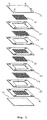
- Fig. 1 shows a DMFC stack consisting of two individual cells, which are arranged between the end plates (1, 2).
- the membrane-electrode assemblies (3) are contacted from one side with the graphite plates (4) and a sealing element (5), on the other side with a wire mesh (6) and another seal (5).
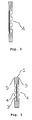
- FIG. 1 The schematic structure of a single bipolar plate is shown in FIG.
- Fig. 3 shows a non-inventive bipolar plate assembly integrated cooling for hydrogen-powered fuel cells.
- the network takes over the distribution function for the cooling medium.
Landscapes
- Life Sciences & Earth Sciences (AREA)
- Engineering & Computer Science (AREA)
- Manufacturing & Machinery (AREA)
- Sustainable Development (AREA)
- Sustainable Energy (AREA)
- Chemical & Material Sciences (AREA)
- Chemical Kinetics & Catalysis (AREA)
- Electrochemistry (AREA)
- General Chemical & Material Sciences (AREA)
- Fuel Cell (AREA)
- Carbon And Carbon Compounds (AREA)
- Electric Double-Layer Capacitors Or The Like (AREA)
- Secondary Cells (AREA)
Description
- Die Erfindung betrifft eine bipolare Plattenanordnung mit bipolarer Platte aus Graphit für den Einsatz in einer Brennstoffzelle sowie verschiedene Verwendungsmöglichkeiten dieser bipolaren Platte.
- In Brennstoffzellen haben Bipolarplatten die Aufgabe, die Reaktanden homogen über die Elektroden zu verteilen. Zudem müssen sie langzeitstabil sein, eine gute Beständigkeit gegen Korrosion sowie eine gute elektronische Leitfähigkeit aufweisen. Ein weiteres Erfordernis ist eine kostengünstige Herstellung einerseits, und andererseits eine möglichst dünne Ausgestaltung der Platte, um ein geringes Volumen der Brennstoffzelle zu gewährleisten.
- Es hat sich gezeigt, daß Metalle wie z. B. nichtrostender Edelstahl die Ansprüche nur teilweise erfüllen. Auf der Kathodenseite von Brennstoffzellen tritt regelmäßig leichte Korrosion auf, während die Anodenseite insbesondere von Direkt-Methanol-Brennstoffzellen (DMFC) unproblematischer ist.
- Graphit hat sich als ein geeignetes Material für Bipolarplatten herausgestellt. Derartige Graphitplatten können beispielsweise durch Fräsen oder auch durch abformende Verfahren hergestellt werden. Nachteilig beim Stand der Technik ist, daß eine doppelseitige Bearbeitung notwendig ist. Im Falle des Spritzgießens ist das doppelseitige Einbringen einer Strömungsverteilerstruktur schwierig, wenn gleichzeitig die bipolare Platte dünn gehalten werden muss. Zum sicheren Entfernen der Platte aus der Spritzgießvorrichtung dürfen gewisse Materialstärken des Grundmaterials nicht unterschritten werden. Ein Richtwert für die Mindestmaterialstärke des Grundmaterials ist ca. 0,8 mm.
- Ein weiterer Nachteil beim Einsatz solcher aus dem Stand der Technik bekannten Platten ist es, daß sich bei einem Brennstoffzellenstapel die Fertigungsungenauigkeiten (Toleranzen) der einzelnen Platten aufsummieren, so daß Teilbereiche der bipolaren Platte im zusammengebauten Zustand eine erhöhte Belastung erfahren. Dabei können sogar Brüche die Folge sein.
- Es ist zudem bekannt, daß bei mit Wasserstoff betriebenen Brennstoffzellen Kühlzellen notwendig sind, um die entstehende Wärme auszukoppeln. Bei Direkt-Methanol-Brennstoffzellen mit flüssigem Anodenkreislauf sind Kühlzellen dagegen nicht notwendig, da hierbei der Wärmeaustrag über den Anodenlcreislauf erfolgen kann.
- Aufgabe der Erfindung ist es, eine einfach herzustellende bipolare Platte aus Graphit zu schaffen, mit der eine gute Gleichverteilung der Reaktanden bewerkstelligt werden kann, die eine dünne Bauweise erlaubt.
- Die Aufgabe der Erfindung wird gelöst durch eine bipolare Plattenanordnung mit bipolarer Platte aus Graphit gemäß Hauptanspruch. Vorteilhafte Ausführungsformen der Erfindung finden sich in den darauf rückbezogenen Ansprüchen.
- Die erfindungsgemäße bipolare Plattenanordnung enthält mindestens eine bipolare Platte aus Graphit. Sie weist auf einer ihrer Seiten eine Verteilerstruktur für die Verteilung eines Betriebsmittels auf. Die gegenüberliegende Seite der bipolaren Platte ist planar ausgestaltet. Eine solche bipolare Platte kann auf einfache Weise aus einer dickeren Graphitplatte hergestellt werden, indem auf eine Seite Verteilerstrukturen eingefräst oder geformt werden.
- Als geeignete Verteilerstrukturen bieten sich beispielsweise parallele Kanäle, Mäander oder auch einzelne Stege in unterschiedlichen Anordnungen an. Diese bipolare Platte weist vorteilhaft eine nur sehr geringe Wandstärke auf, was bei einem Einsatz in einer Brennstoffzelle zu einer günstigen Baugeometrie führt. Typische Wandstärken liegen in einem Bereich von 1,6 bis 5 mm.
- Um auch eine Verteilerstruktur auf der anderen planaren Seite der bipolaren Platte zu realisieren, kann dort vorteilhaft ein dünnes Netz angeordnet werden. So kann eine geringe Stärke der bipolaren Plattenanordnung bei gleichzeitig einfacher Herstellung erzielt werden. Ein Netz hat zudem den Vorteil, dass es Fertigungstoleranzen der graphitischen bipolaren Platte ausgleichen kann. Dadurch können Spannungen, die aufgrund von Bautoleranzen beim Aufbau eines Brennstoffzellenstapels entstehen würden, regelmäßig vermieden werden.
- Beim Einsatz in einer Brennstoffzelle wird die bipolare Platte in einer Ausführungsform der Erfindung derart angeordnet, dass die graphitische Verteilerstruktur an die Kathode grenzt. Ein Netz sorgt auf der anderen Seite der bipolaren Platte für die Verteilung des Brennstoffs über die Anode. Bei einer Direkt-Methanol-Brennstoffzelle kann in dieser Ausführungsform das Netz gleichzeitig die Verteilung des Brennstoffes und des Kühlmediums übernehmen.
- Der Vorteil der erfindungsgemäßen bipolaren Plattenanordnung ihrer einfachen Herstellung und ihrem flexiblen Einsatz. Zusammen mit einem einfachen Verteilernetz wird eine beidseitige Verteilerstruktur realisiert, die zudem ausgleichend auf Bautoleranzen wirkt. Mit dieser Anordnung können auf einfache Weise die Funktionen einer bipolaren Platte mit entsprechender Verteilung der Betriebsstoffe verwirklicht werden. Die erfindungsgemäße bipolare Platte ist sowohl für den Einsatz in einer mit Wasserstoff betriebenen, als auch in einer Direkt-Methanol-Brennstoffzelle geeignet.
- Nachfolgend wird der Gegenstand der Erfindung anhand von Figuren näher erläutert, ohne daß der Gegenstand der Erfindung dadurch beschränkt wird.
- Die Erfindung löst die Aufgabe dadurch, daß die bipolare Platte nur auf der einen Seite strukturiert ist und auf der anderen Seite im wesentlichen planar ist. In Kombination mit einem nachgiebigen Element kann sie vorteilhaft in einer Brennstoffzelle eingesetzt werden. Das zusätzliche nachgiebige Element, z. B. ein Metall- oder Graphitgewebe, hat die folgenden Funktionen:
- Strömungsverteilung
- elektronische Leitung
- Ausgleich der Fertigungsungenauigkeiten
- Die besondere Ausgestaltung der erfindungsgemäßen bipolaren Platte besteht nun darin, daß sie sowohl in Direkt-Methanol-Brennstoffzellen als auch in mit Wasserstoff betriebenen Brennstoffzellen eingesetzt werden kann. Dabei übernimmt das Metallnetz die Aufgabe eines Strömungsverteilers für die Anodenseite.
- Die bipolare Platte ist sowohl für den Einsatz in einer DMFC, als auch in einer Wasserstoff-Brennstoffzelle geeignet.
- In den Figuren sind einige Ausführungsbeispiele der Erfindung dargestellt:
- Die Fig. 1 zeigt einen DMFC-Stapel bestehend aus zwei einzelnen Zellen, die zwischen den Endplatten (1, 2) angeordnet sind. Die Membran-Elektroden-Einheiten (3) sind von der einen Seite her mit den Graphitplatten (4) und einem Dichtungselement (5) kontaktiert, auf der anderen Seite mit einem Drahtgewebe (6) sowie einer weiteren Dichtung (5).
- Den schematische Aufbau einer einzelnen bipolaren Platte ist in der Fig. 2 dargestellt.
- Fig. 3 zeigt eine nicht erfindungsgemässe bipolare Plattenanordnung integrierter Kühlung für mit Wasserstoff betriebene Brennstoffzellen. Dabei übernimmt das Netz die Verteilerfunktion für das Kühlmedium.
Claims (4)
- Bipolare Plattenanordnung mit einer bipolaren Platte aus Graphit für den Einsatz in einer Brennstoffzelle, mit einer Verteilerstruktur auf einer ersten Seite und einer planaren Oberfläche auf der der ersten Seite gegenüberliegenden Seite, gekennzeichnet durch ein Netz, welches auf der planaren Oberfläche der bipolaren Platte angeordnet ist.
- Bipolare Plattenanordnung nach Anspruch 1 mit einer bipolaren Platte mit mehreren Stegen als Verteilerstruktur.
- Bipolare Plattenanordnung nach vorhergehendem Anspruch 1 oder 2 mit einem Netz aus Edelstahl oder Graphitgewebe.
- Brennstoffzelle umfassend wenigstens eine bipolare Plattenanordnung nach einem der Ansprüche 1 bis 3.
Applications Claiming Priority (3)
| Application Number | Priority Date | Filing Date | Title |
|---|---|---|---|
| DE10162871 | 2001-12-20 | ||
| DE10162871A DE10162871A1 (de) | 2001-12-20 | 2001-12-20 | Bipolare Platte aus Graphit |
| PCT/DE2002/004304 WO2003054992A2 (de) | 2001-12-20 | 2002-11-23 | Bipolar platte aus graphit |
Publications (2)
| Publication Number | Publication Date |
|---|---|
| EP1516382A2 EP1516382A2 (de) | 2005-03-23 |
| EP1516382B1 true EP1516382B1 (de) | 2006-05-24 |
Family
ID=7710125
Family Applications (1)
| Application Number | Title | Priority Date | Filing Date |
|---|---|---|---|
| EP02787385A Expired - Lifetime EP1516382B1 (de) | 2001-12-20 | 2002-11-23 | Bipolarplatte aus graphit |
Country Status (4)
| Country | Link |
|---|---|
| EP (1) | EP1516382B1 (de) |
| AT (1) | ATE327577T1 (de) |
| DE (2) | DE10162871A1 (de) |
| WO (1) | WO2003054992A2 (de) |
Families Citing this family (2)
| Publication number | Priority date | Publication date | Assignee | Title |
|---|---|---|---|---|
| DE102004016318A1 (de) * | 2004-03-30 | 2005-10-20 | Reinz Dichtungs Gmbh | Bipolarplatte sowie Verfahren zu deren Herstellung und ein die Bipolarplatte enthaltendes elektrochemisches System |
| DE102016224696A1 (de) | 2016-12-12 | 2018-06-14 | Robert Bosch Gmbh | Bipolarplatte für eine Brennstoffzelle und Brennstoffzelle |
Family Cites Families (4)
| Publication number | Priority date | Publication date | Assignee | Title |
|---|---|---|---|---|
| IT1270878B (it) * | 1993-04-30 | 1997-05-13 | Permelec Spa Nora | Migliorata cella elettrochimica utilizzante membrane a scambio ionico e piatti bipolari metallici |
| AU1764700A (en) * | 1998-12-30 | 2000-07-24 | Ballard Power Systems Inc. | Fuel cell fluid flow field plate and methods of making fuel cell flow field plates |
| US6686083B1 (en) * | 1999-10-20 | 2004-02-03 | Nisshinbo Industries, Inc. | Carbonaceous composite material, process for production thereof, fuel cell separator, and polymer electrolyte fuel cell |
| SE516741C2 (sv) * | 2001-02-27 | 2002-02-26 | Cellkraft Ab | Bipolär platta för bränslecell eller elektrokemisk reaktor samt användning av plattan i en bränslecellstack eller elektrokemisk reaktor |
-
2001
- 2001-12-20 DE DE10162871A patent/DE10162871A1/de not_active Withdrawn
-
2002
- 2002-11-23 EP EP02787385A patent/EP1516382B1/de not_active Expired - Lifetime
- 2002-11-23 AT AT02787385T patent/ATE327577T1/de active
- 2002-11-23 WO PCT/DE2002/004304 patent/WO2003054992A2/de not_active Ceased
- 2002-11-23 DE DE50206943T patent/DE50206943D1/de not_active Expired - Lifetime
Also Published As
| Publication number | Publication date |
|---|---|
| DE10162871A1 (de) | 2003-07-10 |
| EP1516382A2 (de) | 2005-03-23 |
| WO2003054992A2 (de) | 2003-07-03 |
| WO2003054992A3 (de) | 2005-01-27 |
| DE50206943D1 (de) | 2006-06-29 |
| ATE327577T1 (de) | 2006-06-15 |
Similar Documents
| Publication | Publication Date | Title |
|---|---|---|
| DE69932304T2 (de) | Elektrische Kontaktvorrichtung für eine Brennstoffzelle | |
| DE69022244T2 (de) | Stromkollektor für brennstoffzellen. | |
| DE112007002945B4 (de) | Brennstoffzelle mit elastischem Element | |
| EP2130256B1 (de) | Brennstoffzellenstack in leichtbauweise | |
| DE10158771A1 (de) | Brennstoffzellensystem | |
| EP1627445B1 (de) | Elektrolyse- bzw. brennstoffzelle mit druckkissen und verbessertem übergangswiderstand | |
| EP0880802B1 (de) | Hochtemperatur-brennstoffzelle und -stapel mit metallischen verbundleiterplatten | |
| EP1589602B1 (de) | Kontaktfederblech und elektrochemische Batterie mit einem derartigen Kontaktfederblech | |
| EP1516382B1 (de) | Bipolarplatte aus graphit | |
| DE102021127626B4 (de) | Brennstoffzelleneinheit | |
| EP1844513B1 (de) | Interkonnektor für hochtemperaturbrennstoffzellen | |
| DE102019204274A1 (de) | Brennstoffzellenbatterie | |
| DE10039024B4 (de) | Brennstoffzellenstapel mit internen Gasanschlüssen | |
| WO2022128856A2 (de) | Anordnung elektrochemischer zellen | |
| EP1525634B1 (de) | Bipolare platte für eine brennstoffzelle | |
| DE102008051493A1 (de) | Struktur eines Brennstoffzellenstapels | |
| EP1310009B1 (de) | Brennstoffzellenstapel | |
| DE19649456C2 (de) | Hochtemperatur-Brennstoffzelle | |
| EP1358692A1 (de) | Brennstoffzelle | |
| DE2258482C3 (de) | Brennstoffbatterie | |
| DE102020209059A1 (de) | Separatorstrukturvorrichtung für eine Bipolarplatte und Verfahren zur Herstellung einer Separatorstrukturvorrichtung | |
| DE102021006001B3 (de) | Bipolarplatte für eine Brennstoffzelle | |
| DE202024100156U1 (de) | Elektrochemisches System mit Druckvergleichmäßigungsplatte | |
| DE102023131762A1 (de) | Unterdichtung für eine Membran-Elektroden-Einheit einer elektrochemischen Zelle | |
| DE102022108277A1 (de) | Gehäuse, insbesondere für eine leistungselektronische Baugruppe, und Anordnung hiermit |
Legal Events
| Date | Code | Title | Description |
|---|---|---|---|
| PUAI | Public reference made under article 153(3) epc to a published international application that has entered the european phase |
Free format text: ORIGINAL CODE: 0009012 |
|
| 17P | Request for examination filed |
Effective date: 20040518 |
|
| AK | Designated contracting states |
Kind code of ref document: A2 Designated state(s): AT BE BG CH CY CZ DE DK EE ES FI FR GB GR IE IT LI LU MC NL PT SE SK TR |
|
| GRAP | Despatch of communication of intention to grant a patent |
Free format text: ORIGINAL CODE: EPIDOSNIGR1 |
|
| GRAS | Grant fee paid |
Free format text: ORIGINAL CODE: EPIDOSNIGR3 |
|
| GRAA | (expected) grant |
Free format text: ORIGINAL CODE: 0009210 |
|
| AK | Designated contracting states |
Kind code of ref document: B1 Designated state(s): AT BE BG CH CY CZ DE DK EE ES FI FR GB GR IE IT LI LU MC NL PT SE SK TR |
|
| PG25 | Lapsed in a contracting state [announced via postgrant information from national office to epo] |
Ref country code: FI Free format text: LAPSE BECAUSE OF FAILURE TO SUBMIT A TRANSLATION OF THE DESCRIPTION OR TO PAY THE FEE WITHIN THE PRESCRIBED TIME-LIMIT Effective date: 20060524 Ref country code: IT Free format text: LAPSE BECAUSE OF FAILURE TO SUBMIT A TRANSLATION OF THE DESCRIPTION OR TO PAY THE FEE WITHIN THE PRESCRIBED TIME-LIMIT;WARNING: LAPSES OF ITALIAN PATENTS WITH EFFECTIVE DATE BEFORE 2007 MAY HAVE OCCURRED AT ANY TIME BEFORE 2007. THE CORRECT EFFECTIVE DATE MAY BE DIFFERENT FROM THE ONE RECORDED. Effective date: 20060524 Ref country code: SK Free format text: LAPSE BECAUSE OF FAILURE TO SUBMIT A TRANSLATION OF THE DESCRIPTION OR TO PAY THE FEE WITHIN THE PRESCRIBED TIME-LIMIT Effective date: 20060524 Ref country code: NL Free format text: LAPSE BECAUSE OF FAILURE TO SUBMIT A TRANSLATION OF THE DESCRIPTION OR TO PAY THE FEE WITHIN THE PRESCRIBED TIME-LIMIT Effective date: 20060524 Ref country code: CZ Free format text: LAPSE BECAUSE OF FAILURE TO SUBMIT A TRANSLATION OF THE DESCRIPTION OR TO PAY THE FEE WITHIN THE PRESCRIBED TIME-LIMIT Effective date: 20060524 |
|
| REG | Reference to a national code |
Ref country code: GB Ref legal event code: FG4D Free format text: NOT ENGLISH |
|
| REG | Reference to a national code |
Ref country code: CH Ref legal event code: EP |
|
| REG | Reference to a national code |
Ref country code: IE Ref legal event code: FG4D Free format text: LANGUAGE OF EP DOCUMENT: GERMAN |
|
| REF | Corresponds to: |
Ref document number: 50206943 Country of ref document: DE Date of ref document: 20060629 Kind code of ref document: P |
|
| PG25 | Lapsed in a contracting state [announced via postgrant information from national office to epo] |
Ref country code: SE Free format text: LAPSE BECAUSE OF FAILURE TO SUBMIT A TRANSLATION OF THE DESCRIPTION OR TO PAY THE FEE WITHIN THE PRESCRIBED TIME-LIMIT Effective date: 20060824 Ref country code: DK Free format text: LAPSE BECAUSE OF FAILURE TO SUBMIT A TRANSLATION OF THE DESCRIPTION OR TO PAY THE FEE WITHIN THE PRESCRIBED TIME-LIMIT Effective date: 20060824 |
|
| PG25 | Lapsed in a contracting state [announced via postgrant information from national office to epo] |
Ref country code: ES Free format text: LAPSE BECAUSE OF FAILURE TO SUBMIT A TRANSLATION OF THE DESCRIPTION OR TO PAY THE FEE WITHIN THE PRESCRIBED TIME-LIMIT Effective date: 20060904 |
|
| GBT | Gb: translation of ep patent filed (gb section 77(6)(a)/1977) |
Effective date: 20060829 |
|
| PG25 | Lapsed in a contracting state [announced via postgrant information from national office to epo] |
Ref country code: PT Free format text: LAPSE BECAUSE OF FAILURE TO SUBMIT A TRANSLATION OF THE DESCRIPTION OR TO PAY THE FEE WITHIN THE PRESCRIBED TIME-LIMIT Effective date: 20061024 |
|
| NLV1 | Nl: lapsed or annulled due to failure to fulfill the requirements of art. 29p and 29m of the patents act | ||
| ET | Fr: translation filed | ||
| PLBE | No opposition filed within time limit |
Free format text: ORIGINAL CODE: 0009261 |
|
| STAA | Information on the status of an ep patent application or granted ep patent |
Free format text: STATUS: NO OPPOSITION FILED WITHIN TIME LIMIT |
|
| 26N | No opposition filed |
Effective date: 20070227 |
|
| PG25 | Lapsed in a contracting state [announced via postgrant information from national office to epo] |
Ref country code: GR Free format text: LAPSE BECAUSE OF FAILURE TO SUBMIT A TRANSLATION OF THE DESCRIPTION OR TO PAY THE FEE WITHIN THE PRESCRIBED TIME-LIMIT Effective date: 20060825 |
|
| PG25 | Lapsed in a contracting state [announced via postgrant information from national office to epo] |
Ref country code: BG Free format text: LAPSE BECAUSE OF FAILURE TO SUBMIT A TRANSLATION OF THE DESCRIPTION OR TO PAY THE FEE WITHIN THE PRESCRIBED TIME-LIMIT Effective date: 20060824 Ref country code: EE Free format text: LAPSE BECAUSE OF FAILURE TO SUBMIT A TRANSLATION OF THE DESCRIPTION OR TO PAY THE FEE WITHIN THE PRESCRIBED TIME-LIMIT Effective date: 20060524 |
|
| PG25 | Lapsed in a contracting state [announced via postgrant information from national office to epo] |
Ref country code: TR Free format text: LAPSE BECAUSE OF FAILURE TO SUBMIT A TRANSLATION OF THE DESCRIPTION OR TO PAY THE FEE WITHIN THE PRESCRIBED TIME-LIMIT Effective date: 20060524 |
|
| PG25 | Lapsed in a contracting state [announced via postgrant information from national office to epo] |
Ref country code: CY Free format text: LAPSE BECAUSE OF FAILURE TO SUBMIT A TRANSLATION OF THE DESCRIPTION OR TO PAY THE FEE WITHIN THE PRESCRIBED TIME-LIMIT Effective date: 20060524 |
|
| PGFP | Annual fee paid to national office [announced via postgrant information from national office to epo] |
Ref country code: MC Payment date: 20101119 Year of fee payment: 9 |
|
| PGFP | Annual fee paid to national office [announced via postgrant information from national office to epo] |
Ref country code: LU Payment date: 20101216 Year of fee payment: 9 |
|
| PG25 | Lapsed in a contracting state [announced via postgrant information from national office to epo] |
Ref country code: MC Free format text: LAPSE BECAUSE OF NON-PAYMENT OF DUE FEES Effective date: 20111130 |
|
| PG25 | Lapsed in a contracting state [announced via postgrant information from national office to epo] |
Ref country code: LU Free format text: LAPSE BECAUSE OF NON-PAYMENT OF DUE FEES Effective date: 20111123 |
|
| REG | Reference to a national code |
Ref country code: FR Ref legal event code: PLFP Year of fee payment: 14 |
|
| PGFP | Annual fee paid to national office [announced via postgrant information from national office to epo] |
Ref country code: GB Payment date: 20151123 Year of fee payment: 14 Ref country code: DE Payment date: 20151002 Year of fee payment: 14 Ref country code: CH Payment date: 20151123 Year of fee payment: 14 Ref country code: IE Payment date: 20151123 Year of fee payment: 14 |
|
| PGFP | Annual fee paid to national office [announced via postgrant information from national office to epo] |
Ref country code: FR Payment date: 20151124 Year of fee payment: 14 Ref country code: BE Payment date: 20151124 Year of fee payment: 14 Ref country code: AT Payment date: 20151120 Year of fee payment: 14 |
|
| PG25 | Lapsed in a contracting state [announced via postgrant information from national office to epo] |
Ref country code: BE Free format text: LAPSE BECAUSE OF NON-PAYMENT OF DUE FEES Effective date: 20161130 |
|
| REG | Reference to a national code |
Ref country code: DE Ref legal event code: R119 Ref document number: 50206943 Country of ref document: DE |
|
| REG | Reference to a national code |
Ref country code: CH Ref legal event code: PL |
|
| REG | Reference to a national code |
Ref country code: AT Ref legal event code: MM01 Ref document number: 327577 Country of ref document: AT Kind code of ref document: T Effective date: 20161123 |
|
| GBPC | Gb: european patent ceased through non-payment of renewal fee |
Effective date: 20161123 |
|
| PG25 | Lapsed in a contracting state [announced via postgrant information from national office to epo] |
Ref country code: CH Free format text: LAPSE BECAUSE OF NON-PAYMENT OF DUE FEES Effective date: 20161130 Ref country code: LI Free format text: LAPSE BECAUSE OF NON-PAYMENT OF DUE FEES Effective date: 20161130 |
|
| REG | Reference to a national code |
Ref country code: IE Ref legal event code: MM4A |
|
| REG | Reference to a national code |
Ref country code: FR Ref legal event code: ST Effective date: 20170731 |
|
| PG25 | Lapsed in a contracting state [announced via postgrant information from national office to epo] |
Ref country code: AT Free format text: LAPSE BECAUSE OF NON-PAYMENT OF DUE FEES Effective date: 20161123 |
|
| PG25 | Lapsed in a contracting state [announced via postgrant information from national office to epo] |
Ref country code: FR Free format text: LAPSE BECAUSE OF NON-PAYMENT OF DUE FEES Effective date: 20161130 |
|
| PG25 | Lapsed in a contracting state [announced via postgrant information from national office to epo] |
Ref country code: IE Free format text: LAPSE BECAUSE OF NON-PAYMENT OF DUE FEES Effective date: 20161123 Ref country code: DE Free format text: LAPSE BECAUSE OF NON-PAYMENT OF DUE FEES Effective date: 20170601 Ref country code: GB Free format text: LAPSE BECAUSE OF NON-PAYMENT OF DUE FEES Effective date: 20161123 |
|
| REG | Reference to a national code |
Ref country code: BE Ref legal event code: MM Effective date: 20161130 |