EP1667201A2 - Elektrodenloses Beleuchtungssystem - Google Patents
Elektrodenloses Beleuchtungssystem Download PDFInfo
- Publication number
- EP1667201A2 EP1667201A2 EP05254377A EP05254377A EP1667201A2 EP 1667201 A2 EP1667201 A2 EP 1667201A2 EP 05254377 A EP05254377 A EP 05254377A EP 05254377 A EP05254377 A EP 05254377A EP 1667201 A2 EP1667201 A2 EP 1667201A2
- Authority
- EP
- European Patent Office
- Prior art keywords
- case
- area
- waveguide
- separate plate
- microwave generator
- Prior art date
- Legal status (The legal status is an assumption and is not a legal conclusion. Google has not performed a legal analysis and makes no representation as to the accuracy of the status listed.)
- Withdrawn
Links
- 230000005855 radiation Effects 0.000 claims description 16
- 238000012546 transfer Methods 0.000 claims description 11
- 239000000463 material Substances 0.000 claims description 6
- 238000009413 insulation Methods 0.000 claims description 4
- 229910052782 aluminium Inorganic materials 0.000 claims description 3
- XAGFODPZIPBFFR-UHFFFAOYSA-N aluminium Chemical compound [Al] XAGFODPZIPBFFR-UHFFFAOYSA-N 0.000 claims description 3
- 238000001816 cooling Methods 0.000 description 3
- 238000005516 engineering process Methods 0.000 description 2
- DGAQECJNVWCQMB-PUAWFVPOSA-M Ilexoside XXIX Chemical compound C[C@@H]1CC[C@@]2(CC[C@@]3(C(=CC[C@H]4[C@]3(CC[C@@H]5[C@@]4(CC[C@@H](C5(C)C)OS(=O)(=O)[O-])C)C)[C@@H]2[C@]1(C)O)C)C(=O)O[C@H]6[C@@H]([C@H]([C@@H]([C@H](O6)CO)O)O)O.[Na+] DGAQECJNVWCQMB-PUAWFVPOSA-M 0.000 description 1
- 239000012141 concentrate Substances 0.000 description 1
- 239000012774 insulation material Substances 0.000 description 1
- QSHDDOUJBYECFT-UHFFFAOYSA-N mercury Chemical compound [Hg] QSHDDOUJBYECFT-UHFFFAOYSA-N 0.000 description 1
- 229910052753 mercury Inorganic materials 0.000 description 1
- 229910001507 metal halide Inorganic materials 0.000 description 1
- 150000005309 metal halides Chemical class 0.000 description 1
- 238000000034 method Methods 0.000 description 1
- 238000012986 modification Methods 0.000 description 1
- 230000004048 modification Effects 0.000 description 1
- 238000011160 research Methods 0.000 description 1
- 229910052708 sodium Inorganic materials 0.000 description 1
- 239000011734 sodium Substances 0.000 description 1
- 239000000126 substance Substances 0.000 description 1
Images

Classifications
-
- F—MECHANICAL ENGINEERING; LIGHTING; HEATING; WEAPONS; BLASTING
- F21—LIGHTING
- F21S—NON-PORTABLE LIGHTING DEVICES; SYSTEMS THEREOF; VEHICLE LIGHTING DEVICES SPECIALLY ADAPTED FOR VEHICLE EXTERIORS
- F21S13/00—Non-electric lighting devices or systems employing a point-like light source; Non-electric lighting devices or systems employing a light source of unspecified shape
- F21S13/02—Devices intended to be fixed, e.g. ceiling lamp, wall lamp
- F21S13/10—Devices intended to be fixed, e.g. ceiling lamp, wall lamp with a standard, e.g. street lamp
-
- F—MECHANICAL ENGINEERING; LIGHTING; HEATING; WEAPONS; BLASTING
- F21—LIGHTING
- F21V—FUNCTIONAL FEATURES OR DETAILS OF LIGHTING DEVICES OR SYSTEMS THEREOF; STRUCTURAL COMBINATIONS OF LIGHTING DEVICES WITH OTHER ARTICLES, NOT OTHERWISE PROVIDED FOR
- F21V29/00—Protecting lighting devices from thermal damage; Cooling or heating arrangements specially adapted for lighting devices or systems
- F21V29/50—Cooling arrangements
- F21V29/70—Cooling arrangements characterised by passive heat-dissipating elements, e.g. heat-sinks
- F21V29/74—Cooling arrangements characterised by passive heat-dissipating elements, e.g. heat-sinks with fins or blades
-
- F—MECHANICAL ENGINEERING; LIGHTING; HEATING; WEAPONS; BLASTING
- F21—LIGHTING
- F21S—NON-PORTABLE LIGHTING DEVICES; SYSTEMS THEREOF; VEHICLE LIGHTING DEVICES SPECIALLY ADAPTED FOR VEHICLE EXTERIORS
- F21S8/00—Lighting devices intended for fixed installation
- F21S8/08—Lighting devices intended for fixed installation with a standard
- F21S8/085—Lighting devices intended for fixed installation with a standard of high-built type, e.g. street light
-
- F—MECHANICAL ENGINEERING; LIGHTING; HEATING; WEAPONS; BLASTING
- F21—LIGHTING
- F21V—FUNCTIONAL FEATURES OR DETAILS OF LIGHTING DEVICES OR SYSTEMS THEREOF; STRUCTURAL COMBINATIONS OF LIGHTING DEVICES WITH OTHER ARTICLES, NOT OTHERWISE PROVIDED FOR
- F21V23/00—Arrangement of electric circuit elements in or on lighting devices
- F21V23/02—Arrangement of electric circuit elements in or on lighting devices the elements being transformers, impedances or power supply units, e.g. a transformer with a rectifier
-
- F—MECHANICAL ENGINEERING; LIGHTING; HEATING; WEAPONS; BLASTING
- F21—LIGHTING
- F21V—FUNCTIONAL FEATURES OR DETAILS OF LIGHTING DEVICES OR SYSTEMS THEREOF; STRUCTURAL COMBINATIONS OF LIGHTING DEVICES WITH OTHER ARTICLES, NOT OTHERWISE PROVIDED FOR
- F21V29/00—Protecting lighting devices from thermal damage; Cooling or heating arrangements specially adapted for lighting devices or systems
- F21V29/50—Cooling arrangements
- F21V29/70—Cooling arrangements characterised by passive heat-dissipating elements, e.g. heat-sinks
- F21V29/74—Cooling arrangements characterised by passive heat-dissipating elements, e.g. heat-sinks with fins or blades
- F21V29/76—Cooling arrangements characterised by passive heat-dissipating elements, e.g. heat-sinks with fins or blades with essentially identical parallel planar fins or blades, e.g. with comb-like cross-section
- F21V29/763—Cooling arrangements characterised by passive heat-dissipating elements, e.g. heat-sinks with fins or blades with essentially identical parallel planar fins or blades, e.g. with comb-like cross-section the planes containing the fins or blades having the direction of the light emitting axis
-
- F—MECHANICAL ENGINEERING; LIGHTING; HEATING; WEAPONS; BLASTING
- F21—LIGHTING
- F21V—FUNCTIONAL FEATURES OR DETAILS OF LIGHTING DEVICES OR SYSTEMS THEREOF; STRUCTURAL COMBINATIONS OF LIGHTING DEVICES WITH OTHER ARTICLES, NOT OTHERWISE PROVIDED FOR
- F21V29/00—Protecting lighting devices from thermal damage; Cooling or heating arrangements specially adapted for lighting devices or systems
- F21V29/50—Cooling arrangements
- F21V29/70—Cooling arrangements characterised by passive heat-dissipating elements, e.g. heat-sinks
- F21V29/83—Cooling arrangements characterised by passive heat-dissipating elements, e.g. heat-sinks the elements having apertures, ducts or channels, e.g. heat radiation holes
-
- H—ELECTRICITY
- H01—ELECTRIC ELEMENTS
- H01J—ELECTRIC DISCHARGE TUBES OR DISCHARGE LAMPS
- H01J65/00—Lamps without any electrode inside the vessel; Lamps with at least one main electrode outside the vessel
- H01J65/04—Lamps in which a gas filling is excited to luminesce by an external electromagnetic field or by external corpuscular radiation, e.g. for indicating plasma display panels
- H01J65/042—Lamps in which a gas filling is excited to luminesce by an external electromagnetic field or by external corpuscular radiation, e.g. for indicating plasma display panels by an external electromagnetic field
- H01J65/044—Lamps in which a gas filling is excited to luminesce by an external electromagnetic field or by external corpuscular radiation, e.g. for indicating plasma display panels by an external electromagnetic field the field being produced by a separate microwave unit
-
- F—MECHANICAL ENGINEERING; LIGHTING; HEATING; WEAPONS; BLASTING
- F21—LIGHTING
- F21S—NON-PORTABLE LIGHTING DEVICES; SYSTEMS THEREOF; VEHICLE LIGHTING DEVICES SPECIALLY ADAPTED FOR VEHICLE EXTERIORS
- F21S8/00—Lighting devices intended for fixed installation
- F21S8/08—Lighting devices intended for fixed installation with a standard
-
- F—MECHANICAL ENGINEERING; LIGHTING; HEATING; WEAPONS; BLASTING
- F21—LIGHTING
- F21W—INDEXING SCHEME ASSOCIATED WITH SUBCLASSES F21K, F21L, F21S and F21V, RELATING TO USES OR APPLICATIONS OF LIGHTING DEVICES OR SYSTEMS
- F21W2131/00—Use or application of lighting devices or systems not provided for in codes F21W2102/00-F21W2121/00
- F21W2131/10—Outdoor lighting
- F21W2131/103—Outdoor lighting of streets or roads
Definitions
- the present invention relates to an electrodeless lighting system, and particularly, to an electrodeless lighting system capable of lateral lighting like a streetlight and configured to smoothly emit the internally generated heat to the outside.
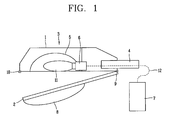
- a conventional streetlight includes: a casing 3 composed of an upper case 1 and a lower case 2; an arm 4 for fixing the casing 3 to a pole (not shown); a reflector 5 installed in the upper case 1; a lamp 11 installed inside the reflector 5; a receptacle 6 for fixing the lamp 11; and a ballast 7 connected to the lamp 11 by a power line 12 to stably apply power to the lamp 11.
- a transparent cover 8 is installed at the lower case 2 so that light coming out of the lamp 11 can be transmitted therethrough.
- the lower case 2 is hingeably connected to the upper case 1, and may be coupled to or disjointed from the upper case 1 by a clamp 10 installed at a front end portion of the upper case 1.
- the lamp 11 used for the conventional streetlight as above has problems that its life span is very short, which causes frequent replacement, and its lighting effect is very low.
- Such an electrodeless lighting system is a lighting device in which microwave energy generated from a magnetron, a power source, is transmitted to a resonator through a waveguide, and is applied to an electrodeless bulb installed in the resonator, and thus the bulb emits visible light or ultraviolet light.
- the electrodeless lighting system has a long life span and good lighting effect compared with incandescent lamps and fluorescent lamps that are generally used.
- the electrodeless lighting system used for lateral lighting such as a streetlight whose technology is open or which is released as products is great in size because it employs a forced air cooling method using a cooling fan to cool heat generated from components. For this reason, it is difficult to make its structure compact and simple.
- the conventional electrodeless lighting system also has a problem that a noise is generated due the driving of the cooling fan and the air flow due to the driving thereof.
- an object of the present invention is to provide an electrodeless lighting system capable of lateral lighting like a streetlight and configured to smoothly emit generated heat to the outside, in which heat generating components and lighting components are installed at separated spaces, respectively.
- an electrodeless lighting system comprising: a first case in which a microwave generator, a waveguide for guiding microwave energy and a luminous part communicating with the waveguide, for emitting light by the microwave energy are installed, wherein one side of the first case is opened so that light from the luminous part is emitted to the outside; a second case coupled to the first case to open or close the opened one side of the first case and configured to pass the light from the luminous part; and a third case positioned at one outer side of the first case, in which a high voltage generator for supplying a high voltage to the microwave generator is installed.
- a plurality of embodiments of an electrodeless lighting system in accordance with the present invention may exist, and, hereinafter, the most preferred embodiment will be described.
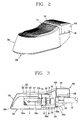
- Figure 2 is a perspective view showing an electrodeless lighting system in accordance with one embodiment of the present invention
- Figure 3 is a longitudinal sectional view of Figure 2
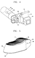
- Figure 4 is a perspective view showing an assembly composed of a luminous part, a waveguide and a microwave generator in accordance with the present invention.
- the electrodeless lighting system in accordance with one embodiment of the present invention includes: a microwave generator 102; a waveguide 103 for guiding microwave energy; a first case 200 having therein a luminous part 120 communicating with the waveguide 103 and emitting light by microwave energy, and having one side opened so that light from the luminous part 120 can be emitted to the outside; a second case 300 coupled to the first case 200 to open or close the opened one side of the first case 1 and configured to pass light emitted from the luminous part 120; a third case 400 positioned at one side outside the case 200 and having therein a high voltage generator 108 for supplying a high voltage to the microwave generator 102.
- the first case 200 is divided into a first area (A) at which the luminous part 120 is positioned, a second area (B) at which the microwave generator 102 and the waveguide 103 are positioned, and a third area (C) receiving a power cable (not shown) for supplying power to the high voltage generator 108 and the microwave generator 102, wherein an arm 110 for supporting the first case 200 is installed at the third area (C).
- the arm 110 is fixed by a bracket 109 formed at one side of the third area (C).
- a plurality of radiation fins 117 are formed at one outer surface of the first case 200 where the first area (A) and the second area (B) are positioned in order to transfer heat generated from the luminous part 120 and the microwave generator 102 to the outside.
- the plurality of radiation fins 117 are entirely formed at one surface opposite to the opened side of the first case 200.
- the plurality of radiation fins 117 may be formed at the entire outer surface of the first case 200 except the opened one side of the first case 200.
- the luminous part 120 includes: a resonator 104 having one end coupled to the waveguide 103 and configured to allow microwave energy introduced from the waveguide 103 to resonate therein and to allow the light to pass therethrough; a bulb 105 positioned to be inclined to a side opposite to one end of the resonator 104 connected to the waveguide 103 on the basis of the center of the resonator 104; and a reflector 107 installed at an inner surface of the first case 200, which faces the opened one side of the first case 200, for reflecting light emitted from the bulb 105 to the opened one side of the first case 200.
- the bulb 105 is rotated by being connected to a motor 106 installed at the second area (B) of the first case 200 by a bulb rotating shaft 105a.
- the bulb 105 passes the center of the resonator 104 and is positioned adjacent to one end opposite to another end of the resonator 104 coupled to the waveguide 103. Accordingly, the bulb rotating shaft 105a is preferably formed long enough to pass the center of the resonator 103.
- a resonance control member 104a for controlling a resonant space in the resonator 104 is installed.
- the resonance control member 104a is installed such that the bulb rotating shaft 105 passes through its center.
- the first area (A) and the second area (B) of the first case 200 are divided by a separate plate 116, and a hole through which the resonator 104 coupled to the waveguide passes is formed at the separate plate 116.
- portions of the separate plate 104 except the hole through which the resonator 104 passes are preferably sealed so as to prevent the air containing foreign substances from being introduced into the first area (A) from the second area (B).
- the separate plate 116 is formed integrally with the first case 200.
- the separate plate 116 may be made of a member of a different material from that of the first case 200. At this time, the separate plate 116 is preferably made of an insulation member.
- the second area (B) and the third area (C) of the first case 200 are also divided by the separate plate 220, and a plurality of holes 220a through which the power cable passes are formed at the separate plate 220.
- the power cable is connected to the high voltage generator 108 and the microwave generator 102 through the third area (C) of the first case 200 from the outside.
- a heat transfer member 113 for connecting the microwave generator 102 to an inner surface of the first case 200 is installed at the second area (B) of the first case 200.
- the heat transfer member 113 is connected to an inner surface of the side where the radiation fin 117 of the first case 200 is formed. Namely, a connection portion 111 formed at one end of the heat transfer member 113 is fixed to an inner surface of the first case 200 by a bolt 112. Also, various methods for fixing the heat transfer member 113 to the first case 200 can be used.
- the second case 300 is pivotably coupled to the first case 200. Namely, one end of the second case 300 is pivotably fixed to the third area (C) of the first case 200 by a pin 300b, and its other end is provided with a clamp 300c so that the second case 300 is separably coupled to a front end of the first area (A) of the first case 200.
- a transparent window 300a is mounted at a portion of the second case 300 covering the first area (A) of the first case 200 so that light coming out of the luminous part 108 is emitted to the outside.
- a plurality of holes 300d are formed at the second case 300 to cool the microwave generator 102 by air. Namely, the holes 300d are formed at a portion of the second case 300, which covers the second area (B) of the first case 200.
- the third case 400 in which the high voltage generator 108 is installed is mounted adjacent to the first case 200 at a certain distance.
- an insulation member 250 is preferably installed between the third case 400 and the first case 200 in order to prevent heat generated from the high voltage generator 108 from being transferred to the inside of the first case.
- a plurality of radiation fins 119 are formed at one outer surface of the third case 400 in order to more effectively radiate heat which is generated from the high voltage generator 108 to the outside.
- the radiation fins 119 may be formed on the entire outer surface of the third case 400.
- the third case 400 is configured to be separable from the first case 200 by a detachable member 118 formed at its one side.
- the first case 200, the second case 300 and the third case 400 are made of an aluminum material.
- Figure 5 is a perspective view showing an electrodeless lighting system in accordance with another embodiment of the present invention
- Figure 6 is a longitudinal sectional view of Figure 5.
- a third case 500 of an electrodeless lighting system in accordance with another embodiment of the present invention is closely attached to the first case 200.
- the third case 50 and the second area of the first case 200 are divided by a separate plate 420.
- the separate plate 420 extends from a separate plate 220 dividing the second area (B) and the third area (C) of the first case 200.
- a plurality of holes 420 are formed at the separate plate 420. Accordingly, the inside of the third case 500 communicates with the outside through a plurality of holes 300d formed at a portion of the second case 300 covering the second area (B) of the first case 200 and the holes of the separate plate 420, so that the air cools not only the microwave generator 102 but also the high voltage generator 108.
- a plurality of radiation fins 460 are formed at one outer surface of the third case 500 so that heat generated from the high voltage generator 108 can be more effectively emitted to the outside.
- the radiation fins 460 may be formed on the entire outer surface of the third case 400.
- the radiation fins 460 formed at the third case 500 closely contact with radiation fins 117 formed at the first case 200, so that internal heat of the first case 200 and the third case 300 can be efficiently emitted to the outside.
- the third case 500 is configured to be separable from the first case 200 by the detachable member 480 formed at its one side.
- the third case 500 is also made of an aluminum material.
- microwave energy is generated at the microwave generator 102.
- the microwave energy generated in such a manner is guided through the waveguide 103 and thus is introduced into the resonator 104 through a slot of the waveguide 103.
- the microwave energy introduced in the resonator 104 resonates therein and also excites a luminous material filled in the bulb 105. Accordingly, light due to plasma is generated, and the generated light passes the resonator 104 and is reflected by the reflector 107, thereby being emitted to the outside through an opened side of the first case 200.
- the microwave generator 102 and the high voltage generator 108 are positioned at separate areas, namely, in the first area (A) and the second area (B) of the first case 200, and the third case 400 and 500, respectively, heat interference therebetween is prevented.
- the air is circulated between the inside of the cases 200 and 500 and the outside through a plurality of holes 300d and 420a formed at the separate plates 116, 220 and 420 for dividing the areas and at the second case 300 for opening/closing the first case 200, so that the heat can be easily diffused to the outside.
- the heat generated at the microwave generator 102 is transferred to the first case 200 through the heat transfer member 113 connected thereto, and the heat transferred to the first case 200 is easily emitted to the outside by heat exchange with the external air through a plurality of radiation fins 177 formed at the outer surface of the first case 200. Also, the heat generated from the high voltage generator 108 is also emitted to the outside through radiation fins 119 and 460 formed at the outer surface of the third case 400 and 500.
- the outside and inside of the case communicate with each other through a plurality of holes formed at separate plates for dividing the areas and the second case for opening/closing the first case, so that the air is circulated therebetween and thus the heat in the case can be easily diffused to the outside.
- a plurality of radiation fins are formed at an outer side of the first case in which the luminous part and the microwave generator are installed and at an outer side of the third case in which the high voltage generator is installed, so that the generated heat can be more efficiently emitted to the outside.
- the electrodeless lighting system in accordance with the present invention has the above described structure and effect, thereby being more effectively used in lateral lighting such as a streetlight.
Landscapes
- Engineering & Computer Science (AREA)
- General Engineering & Computer Science (AREA)
- Physics & Mathematics (AREA)
- Electromagnetism (AREA)
- Plasma & Fusion (AREA)
- Power Engineering (AREA)
- Non-Portable Lighting Devices Or Systems Thereof (AREA)
- Arrangement Of Elements, Cooling, Sealing, Or The Like Of Lighting Devices (AREA)
Applications Claiming Priority (1)
| Application Number | Priority Date | Filing Date | Title |
|---|---|---|---|
| KR1020040085950A KR100631541B1 (ko) | 2004-10-26 | 2004-10-26 | 플라즈마를 이용한 가로등 시스템 |
Publications (2)
| Publication Number | Publication Date |
|---|---|
| EP1667201A2 true EP1667201A2 (de) | 2006-06-07 |
| EP1667201A3 EP1667201A3 (de) | 2009-05-20 |
Family
ID=36121654
Family Applications (1)
| Application Number | Title | Priority Date | Filing Date |
|---|---|---|---|
| EP05254377A Withdrawn EP1667201A3 (de) | 2004-10-26 | 2005-07-13 | Elektrodenloses Beleuchtungssystem |
Country Status (5)
| Country | Link |
|---|---|
| US (1) | US7521852B2 (de) |
| EP (1) | EP1667201A3 (de) |
| JP (1) | JP2006128074A (de) |
| KR (1) | KR100631541B1 (de) |
| CN (1) | CN1767144B (de) |
Families Citing this family (15)
| Publication number | Priority date | Publication date | Assignee | Title |
|---|---|---|---|---|
| KR100748529B1 (ko) | 2005-09-23 | 2007-08-13 | 엘지전자 주식회사 | 무전극 조명기기의 고온 운전형 무전극 전구 및 이를구비한 무전극 조명기기 |
| KR20070035888A (ko) * | 2005-09-28 | 2007-04-02 | 엘지전자 주식회사 | 이종 개구률부를 구비한 무전극 조명기기의 공진기 |
| KR100761264B1 (ko) * | 2005-09-28 | 2007-09-28 | 엘지전자 주식회사 | 알루미늄 공진기를 구비한 무전극 조명기기 |
| KR20070039304A (ko) * | 2005-10-07 | 2007-04-11 | 엘지전자 주식회사 | 초기 점등 수단을 구비한 중출력 무전극 조명기기 |
| US8256938B2 (en) * | 2009-06-15 | 2012-09-04 | Topanga Technologies, Inc. | Method and system for converting a sodium street lamp to an efficient white light source |
| US20130155702A1 (en) * | 2010-09-03 | 2013-06-20 | Stray Light Optical Technologies | Lighting apparatus |
| KR101036860B1 (ko) * | 2010-12-13 | 2011-05-25 | 박범규 | 플라즈마 조명등을 이용한 가로등 |
| CN103875058B (zh) * | 2011-10-07 | 2016-09-14 | 塞拉维申有限公司 | 无强制对流冷却的包含磁控管的微波驱动无电极灯 |
| US20150055334A1 (en) * | 2013-08-26 | 2015-02-26 | Tinson HUANG | Street lighting fixture having an induction lamp |
| US9303848B2 (en) | 2014-08-26 | 2016-04-05 | Grt Tech Co., Ltd. | Light emitting diode lamp structure |
| EP2990716B1 (de) * | 2014-08-26 | 2016-10-19 | GRT Tech Co., Ltd. | Struktur einer LED Lampe |
| USD776859S1 (en) | 2015-04-30 | 2017-01-17 | Hubbell Incorporated | Area luminaire |
| USD828604S1 (en) * | 2016-07-18 | 2018-09-11 | Neptun Light, Inc. | Light fixture |
| USD862762S1 (en) * | 2016-09-29 | 2019-10-08 | RAB Lighting Inc. | Flared LED light fixture |
| USD863643S1 (en) * | 2016-09-29 | 2019-10-15 | RAB Lighting Inc. | Tapered LED light fixture |
Citations (3)
| Publication number | Priority date | Publication date | Assignee | Title |
|---|---|---|---|---|
| US5998934A (en) | 1997-05-15 | 1999-12-07 | Matsushita Electronics Corporation | Microwave-excited discharge lamp apparatus |
| EP1310985A2 (de) | 2001-11-07 | 2003-05-14 | Lg Electronics Inc. | Elektrodenloses Beleuchtungssystem |
| EP1432012A2 (de) | 2002-12-17 | 2004-06-23 | Lg Electronics Inc. | Kühlvorrichtung für Mikrowellenlampe |
Family Cites Families (14)
| Publication number | Priority date | Publication date | Assignee | Title |
|---|---|---|---|---|
| US4485332A (en) * | 1982-05-24 | 1984-11-27 | Fusion Systems Corporation | Method & apparatus for cooling electrodeless lamps |
| JP3202910B2 (ja) * | 1995-12-04 | 2001-08-27 | 松下電器産業株式会社 | マイクロ波放電ランプ |
| US6049170A (en) * | 1996-11-01 | 2000-04-11 | Matsushita Electric Industrial Co., Ltd. | High frequency discharge energy supply means and high frequency electrodeless discharge lamp device |
| EP1192639A1 (de) * | 1999-05-12 | 2002-04-03 | Fusion Lighting, Inc. | Mikrowellen lampe hoher helligkeit. |
| JP2001052655A (ja) * | 1999-08-05 | 2001-02-23 | Toshiba Lighting & Technology Corp | 放電容器、無電極メタルハライド放電ランプ、無電極メタルハライド放電ランプ点灯装置および照明装置 |
| MXPA02003405A (es) * | 2001-08-30 | 2004-07-16 | Lg Electronics Inc | Aparato de iluminacion sin electrodos tipo globo. |
| KR100393817B1 (ko) * | 2001-09-27 | 2003-08-02 | 엘지전자 주식회사 | 무전극 조명기기 |
| KR20030026806A (ko) * | 2001-09-28 | 2003-04-03 | 주식회사 엘지이아이 | 마이크로파의 누출을 차단하는 장치 및 그 방법 |
| JP3988434B2 (ja) * | 2001-10-26 | 2007-10-10 | 松下電工株式会社 | マイクロ波無電極放電ランプ装置 |
| DE60223332T2 (de) * | 2002-01-25 | 2008-02-28 | Lg Electronics Inc. | Elektrodenloses Beleuchtungssystem |
| JP2003249196A (ja) * | 2002-02-25 | 2003-09-05 | Matsushita Electric Works Ltd | マイクロ波無電極放電ランプ点灯装置 |
| KR100451359B1 (ko) * | 2002-03-06 | 2004-10-06 | 주식회사 엘지이아이 | 마이크로 웨이브를 이용한 조명기기 |
| KR100430006B1 (ko) * | 2002-04-10 | 2004-05-03 | 엘지전자 주식회사 | 무전극 조명 시스템 |
| KR100575666B1 (ko) * | 2003-12-13 | 2006-05-03 | 엘지전자 주식회사 | 플라즈마 램프 시스템 |
-
2004
- 2004-10-26 KR KR1020040085950A patent/KR100631541B1/ko not_active Expired - Fee Related
-
2005
- 2005-07-12 US US11/178,428 patent/US7521852B2/en not_active Expired - Fee Related
- 2005-07-13 EP EP05254377A patent/EP1667201A3/de not_active Withdrawn
- 2005-07-20 JP JP2005210001A patent/JP2006128074A/ja active Pending
- 2005-08-04 CN CN2005100885487A patent/CN1767144B/zh not_active Expired - Fee Related
Patent Citations (3)
| Publication number | Priority date | Publication date | Assignee | Title |
|---|---|---|---|---|
| US5998934A (en) | 1997-05-15 | 1999-12-07 | Matsushita Electronics Corporation | Microwave-excited discharge lamp apparatus |
| EP1310985A2 (de) | 2001-11-07 | 2003-05-14 | Lg Electronics Inc. | Elektrodenloses Beleuchtungssystem |
| EP1432012A2 (de) | 2002-12-17 | 2004-06-23 | Lg Electronics Inc. | Kühlvorrichtung für Mikrowellenlampe |
Also Published As
| Publication number | Publication date |
|---|---|
| JP2006128074A (ja) | 2006-05-18 |
| CN1767144B (zh) | 2010-05-05 |
| KR100631541B1 (ko) | 2006-10-09 |
| US7521852B2 (en) | 2009-04-21 |
| CN1767144A (zh) | 2006-05-03 |
| US20060087257A1 (en) | 2006-04-27 |
| KR20060036837A (ko) | 2006-05-02 |
| EP1667201A3 (de) | 2009-05-20 |
Similar Documents
| Publication | Publication Date | Title |
|---|---|---|
| US7521852B2 (en) | Electrodeless lighting system | |
| KR100396772B1 (ko) | 마이크로파를 이용한 조명기구 | |
| JP2005174938A (ja) | 無電極ランプシステム | |
| CN100459024C (zh) | 等离子体照明系统的冷却设备 | |
| JP4170681B2 (ja) | マイクロ波を利用した無電極放電ランプ | |
| KR100531908B1 (ko) | 무전극 조명기기의 마이크로파 집속장치 | |
| RU2225659C2 (ru) | Осветительное устройство, использующее микроволновую энергию | |
| US20140246971A1 (en) | Microwave driven electrodeless lamp comprising magnetron without forced convective cooling | |
| KR100565342B1 (ko) | 무전극 조명기기의 미러구조 | |
| JPH09320543A (ja) | マイクロ波無電極放電光源装置 | |
| JP2003151301A (ja) | 無電極照明機器 | |
| KR100421395B1 (ko) | 무전극 램프의 냉각장치 | |
| KR100430012B1 (ko) | 무전극 램프의 열변형 방지장치 | |
| KR100386250B1 (ko) | 무전극 램프의 케이싱 구조 | |
| KR100314015B1 (ko) | 마이크로 웨이브 조명기기의 냉각 장치 | |
| KR100831210B1 (ko) | 무전극 조명기기가 적용된 가로등 | |
| KR100459452B1 (ko) | 무전극 램프의 반사구 보호장치 | |
| KR100400401B1 (ko) | 무전극 조명기기의 램프 방열구조 | |
| KR100414090B1 (ko) | 마이크로파를 이용한 조명시스템 | |
| KR100608881B1 (ko) | 무전극 조명기기의 초기점등장치 | |
| KR20070117386A (ko) | 마이크로파를 이용한 조명기기 및 그의 공진기 | |
| KR20020059536A (ko) | 마그네트론 일체형 마이크로파 조명 장치 | |
| KR20060128511A (ko) | 무전극 조명기기 | |
| KR20040057680A (ko) | 플라즈마 조명장치 | |
| KR20030092168A (ko) | 무전극 램프의 반사장치 |
Legal Events
| Date | Code | Title | Description |
|---|---|---|---|
| PUAI | Public reference made under article 153(3) epc to a published international application that has entered the european phase |
Free format text: ORIGINAL CODE: 0009012 |
|
| AK | Designated contracting states |
Kind code of ref document: A2 Designated state(s): AT BE BG CH CY CZ DE DK EE ES FI FR GB GR HU IE IS IT LI LT LU LV MC NL PL PT RO SE SI SK TR |
|
| AX | Request for extension of the european patent |
Extension state: AL BA HR MK YU |
|
| PUAL | Search report despatched |
Free format text: ORIGINAL CODE: 0009013 |
|
| AK | Designated contracting states |
Kind code of ref document: A3 Designated state(s): AT BE BG CH CY CZ DE DK EE ES FI FR GB GR HU IE IS IT LI LT LU LV MC NL PL PT RO SE SI SK TR |
|
| AX | Request for extension of the european patent |
Extension state: AL BA HR MK YU |
|
| 17P | Request for examination filed |
Effective date: 20091015 |
|
| 17Q | First examination report despatched |
Effective date: 20091201 |
|
| AKX | Designation fees paid |
Designated state(s): DE GB IT |
|
| STAA | Information on the status of an ep patent application or granted ep patent |
Free format text: STATUS: THE APPLICATION IS DEEMED TO BE WITHDRAWN |
|
| 18D | Application deemed to be withdrawn |
Effective date: 20120201 |