EP1667084A1 - Erfassung des gewünschten Halts - Google Patents
Erfassung des gewünschten Halts Download PDFInfo
- Publication number
- EP1667084A1 EP1667084A1 EP05300960A EP05300960A EP1667084A1 EP 1667084 A1 EP1667084 A1 EP 1667084A1 EP 05300960 A EP05300960 A EP 05300960A EP 05300960 A EP05300960 A EP 05300960A EP 1667084 A1 EP1667084 A1 EP 1667084A1
- Authority
- EP
- European Patent Office
- Prior art keywords
- stop
- vehicle
- destination
- receiving device
- assistance system
- Prior art date
- Legal status (The legal status is an assumption and is not a legal conclusion. Google has not performed a legal analysis and makes no representation as to the accuracy of the status listed.)
- Granted
Links
Images



Classifications
-
- G—PHYSICS
- G08—SIGNALLING
- G08G—TRAFFIC CONTROL SYSTEMS
- G08G1/00—Traffic control systems for road vehicles
- G08G1/123—Traffic control systems for road vehicles indicating the position of vehicles, e.g. scheduled vehicles; Managing passenger vehicles circulating according to a fixed timetable, e.g. buses, trains, trams
- G08G1/133—Traffic control systems for road vehicles indicating the position of vehicles, e.g. scheduled vehicles; Managing passenger vehicles circulating according to a fixed timetable, e.g. buses, trains, trams within the vehicle ; Indicators inside the vehicles or at stops
Definitions
- the present invention relates to an on-board assistance system for the users of a vehicle serving several predetermined stops and a support infrastructure using such a support system.
- the assistance system of the present invention is particularly suitable for buses but can be applied in different modes of public transport, such as the metro, urban or regional trains, for example.
- a system for assisting a public transport user is described in document GB 2 322 725, in which a portable reception device comprising a receiver allows the user to be warned when approaching a predetermined destination stop.
- Transmitters capable of transmitting a radio frequency signal comprising an identification code are arranged near said stops. Each transmitter continuously transmits the identification code associated with it. When the vehicle enters the range of the transmitter, it receives the corresponding code. The receiving device compares the received code and the destination code that it has in memory to determine if the destination station is approaching. In the case where the destination station is approaching, the receiving device warns the user.
- programming terminals allow the programming of reception devices.
- Such a support system nevertheless has several disadvantages.
- Such a support system is complicated and expensive to deploy, since each stop, or more generally each place whose approach must be signaled, requires the installation of a transmitter.
- such transmitters are not protected from vandalism or natural wear and tear.
- such an assistance system can easily be disturbed by the radiation of other devices, especially in urban areas, which can lead to reception problems.
- such a support system is difficult to evolve, since each change of a path requires re-installing new transmitters, which requires long and expensive work.
- the present invention aims to provide assistance system that avoids at least some of the aforementioned drawbacks.
- Another object of the invention is to provide a scalable assistance system, easy to deploy, which allows a user to be notified when approaching a predetermined stop.
- the invention relates to an assistance system for the users of a vehicle serving a transmission line including several predetermined stops which are associated predetermined stopping identification codes, said assistance system comprising a radiofrequency transmitter for transmitting, to a portable reception device, one of said identification codes corresponding to a stop near which said vehicle is located, characterized in that said assistance system is embedded in said vehicle, said assistance system comprising a satellite location receiver able to determine a current position of said vehicle from signals emitted by satellites, a geographical database defining a proximity zone associated with each of said stops, a processing means adapted to detect, from said current position, the presence of said vehicle in a e of said proximity zones and to select said stopping identification code associated with stopping in the proximity zone from which the presence of said vehicle is detected, said radiofrequency transmitter being arranged in said vehicle so as to emit, at least inside said vehicle, said identification code selected.
- the stops and the proximity zones are defined by data recorded in the on-board assistance system, it is very simple to adapt them to any transmission line whatever the positions of the stops.
- This assistance system is therefore more flexible than assistance system using fixed transmitters, for which the proximity area, which is equal to the range of the transmitter, is difficult to control.
- the proximity zones may be of any shape.
- said geographical database comprises data defining each of said proximity zones by a respective polygon whose vertices are defined by latitudes and longitudes stored in said geographical database.
- said geographical database defines said proximity zones so as to position each of said proximity zones substantially upstream of said associated stop with respect to the direction of movement of the vehicle in which said stop is served.
- Such a definition of the proximity zones makes it possible to warn the user with a certain advance and to avoid detecting a stop already passed.
- said assistance system comprises a traffic direction indicator to indicate a current direction of circulation of said vehicle, said geographical database comprising data defining, for each of said stops, a direction of circulation of the vehicle in which said stop is likely to be served, said processing means being able to select stops likely to be served in the current direction of the vehicle to detect the presence of the vehicle only among the areas of proximity associated with said selected stops.
- said processing means is adapted to position said traffic direction indicator in response to the detection of the presence of the vehicle in the proximity zone of a terminus of said transport line.
- said processing means is adapted to position said traffic direction indicator in response to the detection of the presence of the vehicle in the proximity zone of a terminus of said transport line.
- said geographical database comprises data defining the names of said stops, an identical stop identification code being associated with several of said stops bearing the same name and served in different traffic directions.
- said geographical database comprises data defining the names of said stops, an identical stop identification code being associated with several of said stops bearing the same name and served in different traffic directions.
- said geographical database includes a file by stopping the transport line, said file including a stop name, a direction of service and a definition of proximity zone.
- said assistance system comprises a programming device disposed in said vehicle, said programming device comprising a user-operable input interface for selecting a destination stop and an output interface. intended to cooperate with said receiving device for storing in said receiving device a destination code corresponding to said destination stop.
- said destination code is identical to the stop identification code associated with said selected destination stop.
- the destination code, sent by the programming device is not necessarily identical to the identification code, transmitted by the radiofrequency transmitter, of the destination stop, since the receiver can carry out a correspondence between these codes.
- said input interface comprises a touch screen for displaying a list of stops of said transmission line. It is also possible to provide any type of input interface on the programming devices, for example an input interface comprising a voice recognition module.
- said output interface comprises a radio frequency transmitter.
- said programming device comprises a correspondence management module able to identify a correspondence stop, where the user must change the transmission line, and another transport line that the user must use to reach his stop of destination.
- the subject of the invention is also an assistance infrastructure characterized in that it comprises a support system mentioned above and a portable reception device, said reception device comprising a receiver able to receive said stop identification code. transmitted by the radiofrequency transmitter when said receiving device is inside said vehicle, said receiving device comprising a memory capable of storing a destination code, corresponding to a destination stop desired by the user, said receiving device comprising comparison means adapted to compare said destination code and said received identification code and said reception device comprising alert means adapted to alert the user of a correspondence between said stored destination code and said code stop identification received.
- said receiving device is integrated in a mobile phone.
- said receiving device comprises a voice recognition module for voice programming said at least one destination station in said receiving device.
- said alerting means comprises a light warning means.
- said alerting means comprises an audible warning means.
- said warning system comprises a means of vibration.
- said method comprises a step of storing in said receiving device a destination code by means of a programming terminal, said programming terminal comprising an input interface for selecting the destination stop.
- said method comprises the steps of determining, with the aid of said programming terminal, a correspondence stop where the user must change lines to reach said destination stop and to store in said reception device an identification code. said judgment of correspondence.
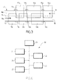
- a bus 1 intended to serve several predetermined stops 11a, 11b, 13a, 13b, 15a and 15b (FIG. 3) along a transport line L1 (FIGS. 3 and 6). ) having two terminals A and B.
- the bus 1 is equipped with an onboard assistance system 2.
- the assistance system 2 comprises a satellite positioning system 3, a computer 4 and a transmitter 5.
- Each stop 11a, 11b, 13a, 13b, 15a and 15b or terminus A and B has an identification code which is associated.
- This assistance system is intended to form an assistance infrastructure in association with portable devices for bus users.
- all the buses serving this line L1 are equipped in the same way.
- the location system 3 is a GPS receiver, which is able to determine a current position of the bus 1 from signals emitted by satellites 6, in a manner known per se.
- the GPS receiver 3 transmits the current position data in the form of a latitude-longitude pair to the computer 4.
- the computer 4 is intended to process the signals received by the GPS receiver 3.
- the computer 4 comprises a geographic database 7 which includes files 7a, for example in XML.
- files 7a for example in XML.
- File 7a contains data called "service direction".
- the direction of service corresponds to the direction of movement of the bus 1 in which the stop 15a is likely to be served.
- the value "1" corresponds to a stop served when the bus is traveling on the line L1 in the direction of the arrow 16, and the value "0" corresponds to a stop served when the bus is traveling in the direction of the arrow 17.
- the file 7a contains location data, between the ⁇ location> line and the ⁇ / location> line.
- the location data makes it possible to define a rectangular proximity zone 14a associated with the stop 15a, by specifying the geographical data of the vertices of a rectangle, namely two latitudes and two longitudes.
- this rectangle is specified by an upper left vertex (UL) and a lower right vertex (DR).
- the file 7a also contains information data relating to the stop 15a, between the line ⁇ info> and the line ⁇ / info>, namely the name of the stop 15a, that is to say GARE , and the line L1 on which the stop 15a is located. This information data is intended to be transmitted to the receiving device 20, in a manner to be described in detail below.
- the stops 11a and 11b bear the same name, namely THEATER
- judgments 13a and 13b bear the same name, namely MAIRIE
- both judgments 15a and 15b bear the same name, namely GARE.
- the stops 11a, 13a and 15a are served when the bus 1 circulates in the street 18 in the direction of the arrow 16 and the stops 11b, 13b and 15b are served when the bus 1 circulates in the street 18 in the direction of the arrow 17.
- Nearby areas are also associated with all stops, including Terminals A and B. Street 18 has two lanes 18a and 18b, separated by a line 19.
- Each zone 10a, 10b, 12a, 12b, 14a or 14b extends upstream of the stop 11a, 11b, 13a, 13b, 15a or 15b with which it is associated.
- the size of an area is defined as the area that defines it.
- the size of each zone 10a, 10b, 12a, 12b, 14a or 14b is defined independently of the size of the other zones. For example, when the bus 1 flows in the direction of the arrow 16, if the stop 13a is close to the stop 15a, it is not desired that the stop 13a is announced before the bus 1 stops at judgment 15a.
- the zone 12a must therefore be sufficiently small so that the zone 12a does not contain the stop 15a.
- stop 11a can influence the size of the zones 10a, 10b, 12a, 12b, 14a and 14b. For example, if the stop 11a is located on a fast lane it can be defined by a relatively large area 10a because the bus 1 can get there faster than elsewhere and the users must be warned with a certain advance notice, therefore sufficiently far from stop 11a.
- the stops and the proximity zones are defined by data recorded in the on-board assistance system, it is very simple to adapt to any transmission line regardless of the positions of the stops, which are not necessarily face to face.
- the computer 4 includes a position indicator that corresponds to the direction of movement of the bus.
- the position indicator is updated with each change of direction, as will be described in detail below.
- the position indicator is an integer variable.
- the position indicator is "1" when bus 1 runs in the direction of arrow 16 and "0" when bus 1 is traveling in the direction of arrow 17.
- the computer 4 is also equipped with an operating system, for example linux or windows.
- the definition files of the proximity zones 7a can be updated by copying files (floppy disk, USB key, etc.). It is therefore very simple to update the assistance system 2, for example when the path of the bus 1 changes.
- the computer 4 is connected to the transmitter 5.
- the transmitter 5 is a radio frequency transmitter which emits for example in the 433 MHZ band.
- the signal emitted by the transmitter 5 has for example a power of about 1 mW and a range of about 200-300m. However, a range of approximately 10m is generally sufficient to cover the interior space of the bus 1.
- the power can be adapted to reduce the coverage area.
- a programming terminal 30 is shown for programming the reception device 20.
- a programming terminal 30 can be arranged in the bus 1, as can be seen in FIG. 1.
- the terminal 30 includes an interface input in the form of a touch screen 31 allowing a bus user to choose the destination stop where the user wants to go down and whose identification code must be stored in the memory 24 as the destination code.
- the screen 31 includes a menu 32 for selecting each of the stops 11a, 11b, 13a, 13b, 15a, 15b, A or B of the line L1. Arrows 33 make it possible to go through the list 34 of the stops 11a, 11b, 13a, 13b, 15a and 15b including the terminals A and B on the line L1.
- the terminal 30 also has an output interface in the form of a radio frequency transmitter 36 for transmitting to a receiving device 20 the programming data.
- the transmission is a transmission at very short range to avoid programming other receiving devices 20 that may be nearby.
- the transmitter 36 operates at the same frequency as the transmitter 5, which makes it possible to use a single corresponding receiver in the reception device 20.
- a receiving device 20 which comprises a housing 26.
- the receiving device 20 comprises a receiver 22 adapted to the transmitter 5, adapted to receive signals in the 433 MHz band.
- the architecture of the receiving device 20 is based on a microprocessor BasicStamp type 21 associated with a module RF / 433MHz 22.
- the receiving device 20 comprises a display screen 23, for example a LCD display 2 * 16 characters.
- the receiving device 20 also comprises a memory 24, for example of the EPROM type, which enables it to memorize the destination codes associated with the desired destination stops by the user.
- the receiving device 20 also comprises an alert system 27, for example an audible alarm.
- the receiving device 20 also comprises control buttons 25, which allow the user to control the receiving device 20 for example to turn it on or off.
- Step 70 is to detect the current position of the bus 1 with the GPS receiver 3.
- position data is received by the GPS receiver 3, it transmits it to the computer 4 and proceeds to step 71.
- Step 71 compares the received position data with the proximity associated with the starting terminals of the bus 1, namely for example the terminals A and B.
- the computer 4 compares the proximity area defined in each of the two files 7a associated with the terminus of departure with the position data received.
- step 72 which consists of adjusting the value of the position indicator to indicate the direction of movement of the bus 1 from this terminus of departure, namely for example the direction 16 from the terminus A and the direction 17 from the terminus B. Then we return to step 70. Otherwise, we return to step 70.
- the departure terminus and the terminus of arrival of a bus at a given location are not necessarily confused. It is quite possible to provide a proximity zone associated with the stop where the passengers are coming down (terminus of arrival) and a zone of proximity associated with the stop where the passengers go up (terminus of departure).
- the step 80 is to select in the programming terminal 30 the desired destination stop from the list of all the stops 11a, 11b, 13a, 13b, 15a or 15b including the terminus A or B. This selection is made using the touch screen 31.
- Step 81 is an optional step that is not used in this embodiment and will be described in detail later.
- the step 82 consists in transmitting a signal containing the identification code and the name of the destination stop selected by the user, the signal being sent by the terminal 30 to the receiving device 20.
- the transmitted signal also includes a programming instruction, to indicate to the reception device 20 that the identification code and the name must be stored in the memory 24.
- a audible signal for validation of the reception device 20 confirms the registration of the destination code and the stop name in the memory 24.
- the user can perform this programming when it is mounted in the bus 1 or during its journey.
- Step 90 consists of to detect the current position of the bus 1 with the GPS receiver 3.
- the computer 4 compares the received position data with the proximity zones 10a, 10b, 12a, 12b, 14a and 14b associated with each stop 11a, 11b, 13a, 13b, 15a and 15b including each terminus A and B.
- the computer 4 analyzes each file 7a.
- the computer 4 For each file 7a, the computer 4 begins by comparing the value of the direction of service mentioned in the file 7a with the value of the position indicator. If they are identical, the computer 4 compares the latitude and longitude provided by the GPS receiver 3 with the latitudes and longitudes of the vertices of the proximity area defined in the file 7a. If the current position of the bus 1 is not in this zone, the computer 4 proceeds to the next file 7a. If the position data does not correspond to any zone near the stops of the line, it returns to step 90. As long as the bus 1 is not in an area close to the stops of the line, then one carries out a loop between step 90 and step 91.
- bus 1 is considered to be running on line L1 in the direction of arrow 16.
- GPS receiver 3 receives position data and step 91 is carried out.
- step 91 the computer 4 makes the comparisons.
- it analyzes the file 7a associated with the zone 14a, it detects that the value of the service direction of this file 7a is equal to the value of the position indicator.
- the computer 4 therefore compares the current position data of the bus 1 with the proximity zone 14a defined in this file 7a. The computer 4 thus detects that the bus 1 is in the zone 14a, so that the bus 1 approaches the stop 15a, and one goes to the step 92.
- the step 92 consists of controlling the transmitter 5 to it emits a modulated signal containing the identification code corresponding to the stop 15a.
- the emitted signal also includes a detection instruction, to indicate to the receiving device 20 that the identification code must be compared with the stored destination code.
- the identification code When the identification code has been issued, it returns to step 90. Thus, this loop is performed continuously by the embedded system.
- the housing 26 is portable and transported by the user who is in the bus 1. For example, it is considered that the user wishes to go to the stop 13a and that he programmed his receiving device 20 accordingly.
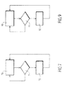
- FIG. 10 there is shown a block diagram describing the steps performed by the reception device 20 to alert the user when approaching his destination stop 11a, 11b, 13a, 13b, 15a or 15b. Including terminus A or B.
- Step 100 consists of receiving an identification code transmitted by the transmitter 5.
- the reception device 20 receives an identification code, it proceeds to step 101.
- the step 101 is to compare the received identification code with the stored destination code.
- step 102 When the receiving device 20 receives the identification code corresponding to the stop 15a, it compares it with the destination code corresponding to the stop 13a but there is no equality, so we return to the step 100, as indicated by the arrow 103.
- the device 20 receives the code corresponding to the stop 13a, it goes to the step 101 and compares the codes. Since the identification code received by the reception device 20 corresponds to the destination code stored in the memory 24, step 102 is proceeded to.
- the step 102 consists in alerting the user by a sound or vibration signal and display on the screen 23 the name of the destination stop previously stored in the memory 24. The user can stop the notification sent by his receiving device by the use of the buttons 25. Alternatively, the stop name could be issued by the transmitter 5 each time it issues a stop identification code.
- step 102 has been performed, return to step 100.
- a terminal 30 is disposed in each of the buses 1.
- terminals 30 may be outside the buses 1, for example in bus shelters or correspondence nodes.
- the terminal 30 includes the list of all the stops of the transport network, namely for example all stops lines L1, L2 and L3 and allows the user to select any of these stops as a desired destination.
- the terminal 30 is connected to the computer 4.
- the computer 4 transmits in real time current position data from the bus 1 to the terminal 30.
- the programming terminal 30 has a correspondence management module, which enables it to determine the correspondences that the user must perform.
- the correspondences are the line changes that the user may have to make to get to his destination stop.
- the bus stops are the stops where the user must change lines to reach his destination stop.
- programming of the receiving device 20 includes step 81.
- Step 80 corresponds to selecting the destination stop, in the same manner as in the first mode of production.
- a user takes the bus 1 of the line L1 and wants to go to the terminus C of the line L3, he selects this destination in the programming terminal 30 inside the bus 1.
- the programming terminal 30 determines the shortest path to go from the current position of the bus 1 to the terminus C using its correspondence management module .
- Step 182 consists of transmitting a programming instruction and destination data, namely the identification code and the name of the destination stop.
- the terminal 30 transmits the identification code and the stop name corresponding to the stop where the user must leave the first line, ie, for example, stop 15a, and a frame containing information on the second line and the direction that the user must take, that is to say for example the line L2 direction D.
- the following correspondence is identified by the identification code and the name corresponding to the stop where the user must leave the second line, namely the stop 9 and a frame containing information relating to the third line and the direction that the user must take, that is to say line L3 and direction C.
- the warning system 27 is triggered in the same manner as in the first embodiment.
- the screen 23 displays the name of the stop 15a and the line L2 that the user must take to arrive at the terminus C, as shown in Figure 11.
- the user does not need to program his reception device 20 since the latter has already memorized the destination stop C, as well as the corresponding correspondence stop 9.
- the receiving device 20 makes it possible to alert the user at each correspondence stop 15a and 9 by indicating which line to take L2 and L3, then to alert him when approaching the stop of destination C.
- the correspondence management can be used on a transport network which comprises any number of lines and any number of matches between the lines.
- This assistance system 2 is adapted to a transport network using buses 1, but can also be used on any type of transport network.
- the receiving device 20 which is programmed by voice.
- the receiving device has a memory for previously storing the name of the stops and the identification codes of all the stops of the line.
- This is equipped with a voice recognition module to program the name of the desired destination stop.
- a switch toggles the receiving device into voice programming mode. he Just say the name the stop of destination. If the name is recognized by the module, that is to say if the name has been memorized, it will emit a confirmation tone.
- a separate programming terminal is not necessary in this case.
- the receiving device can permanently display the current station as well as the destination stop that it has in memory, as shown in FIG. 12.
- the receiving device 20 can be integrated in a mobile phone equipped with a wireless communication technology, for example WiFi technology. In this case, the programming terminals 30 are no longer needed.
- an application can be downloaded automatically, after validation of the user, when the phone is in the WiFi zone of bus 1.
- the warning means 27 may be arbitrary, such as light, sound, vibration or display.
- the vibration of the receiving device 20 at the approach of its destination stop allows it to be autonomous to use public transport.
- the receiving device may comprise control buttons for entering programming mode or erasing the memory 24.
- a radiofrequency link between the programming terminal 30 and the receiving device 20 is particularly suitable since it makes it possible to program the reception device 20 even if it remains in the user's pocket, since this type of connection is little directive. Nevertheless, the programming of the reception device 20 can be carried out with an infrared link or by any other means of data transfer.
- the location of the terminals 30 in bus shelters, railway stations or airports.
- the programming terminals 30 can be coupled to ATM terminals already existing in the stations. With the purchase of the ticket, the receiving device 20 can thus be automatically programmed with the chosen destination.
- the destination codes transmitted by the terminals 30 when programming the reception device 20 may be different from the identification codes issued by the on-board assistance system when the reception device 20 has a correspondence rule. between the stored destination codes and the received identification codes.
- the proximity zones 10a, 10b, 12a, 12b, 14a and 14b can be defined in the form of any polygon whose vertices are marked by their latitude and longitude. Other geometric shapes are still possible.
- the XML localization files 7a can be updated by a means of communication (Satellite, WiFi, etc.) if the embedded computer 4 has such means.
- the 433 MHz is a free band that is suitable for this type of application. Transmitters of this type are known and inexpensive. Nevertheless, the system can operate on another frequency band (2.4 GHz, Wifi for example).
- the traffic direction indicator can be initialized using a manual setting.
- the computer may include an additional file with the order of the stops, to analyze the files 7a in the order of the stops to save time. Such scheduling can also be done using pointers present in each file 7a. Each pointer pointing to file 7a corresponding to the next stop.
Landscapes
- Engineering & Computer Science (AREA)
- Radar, Positioning & Navigation (AREA)
- Remote Sensing (AREA)
- Physics & Mathematics (AREA)
- General Physics & Mathematics (AREA)
- Traffic Control Systems (AREA)
- Holo Graphy (AREA)
- Input Circuits Of Receivers And Coupling Of Receivers And Audio Equipment (AREA)
- Optical Head (AREA)
- Electric Propulsion And Braking For Vehicles (AREA)
Applications Claiming Priority (1)
| Application Number | Priority Date | Filing Date | Title |
|---|---|---|---|
| FR0412856A FR2879001A1 (fr) | 2004-12-03 | 2004-12-03 | Detection de l'arret souhaite |
Publications (2)
| Publication Number | Publication Date |
|---|---|
| EP1667084A1 true EP1667084A1 (de) | 2006-06-07 |
| EP1667084B1 EP1667084B1 (de) | 2007-02-14 |
Family
ID=34952559
Family Applications (1)
| Application Number | Title | Priority Date | Filing Date |
|---|---|---|---|
| EP05300960A Expired - Lifetime EP1667084B1 (de) | 2004-12-03 | 2005-11-23 | Erfassung des gewünschten Halts |
Country Status (4)
| Country | Link |
|---|---|
| EP (1) | EP1667084B1 (de) |
| AT (1) | ATE354150T1 (de) |
| DE (1) | DE602005000570D1 (de) |
| FR (1) | FR2879001A1 (de) |
Cited By (5)
| Publication number | Priority date | Publication date | Assignee | Title |
|---|---|---|---|---|
| CN104157162A (zh) * | 2014-07-15 | 2014-11-19 | 深圳市盛世任我行科技有限公司 | 盲人公交语音导引系统 |
| CN105405288A (zh) * | 2015-12-20 | 2016-03-16 | 深圳步步汇通科技有限公司 | 智能导盲系统 |
| WO2017012227A1 (zh) * | 2015-07-23 | 2017-01-26 | 广州华途信息科技有限公司 | 一种城市公共交通视障人士助乘系统及方法 |
| US10095229B2 (en) | 2016-09-13 | 2018-10-09 | Ford Global Technologies, Llc | Passenger tracking systems and methods |
| CN109118756A (zh) * | 2018-09-27 | 2019-01-01 | 河海大学 | 一种基于信息交互的盲人公交引航系统 |
Citations (4)
| Publication number | Priority date | Publication date | Assignee | Title |
|---|---|---|---|---|
| US6374176B1 (en) * | 1996-08-13 | 2002-04-16 | Nextbus Information Systems, Inc. | Public transit vehicle arrival information system |
| WO2002048987A1 (en) * | 2000-12-14 | 2002-06-20 | Koninklijke Philips Electronics N.V. | Method of providing travel information to a mobile communications device |
| DE10225096A1 (de) * | 2002-06-05 | 2003-12-18 | Wolfgang Beyer | Verfahren und mobile Computereinrichtung zur Routenplanung |
| EP1424667A2 (de) * | 2002-11-20 | 2004-06-02 | Nec Corporation | Gerät und Verfahren zur Leitung von Transportfahrzeugen |
-
2004
- 2004-12-03 FR FR0412856A patent/FR2879001A1/fr active Pending
-
2005
- 2005-11-23 EP EP05300960A patent/EP1667084B1/de not_active Expired - Lifetime
- 2005-11-23 DE DE602005000570T patent/DE602005000570D1/de not_active Expired - Lifetime
- 2005-11-23 AT AT05300960T patent/ATE354150T1/de not_active IP Right Cessation
Patent Citations (4)
| Publication number | Priority date | Publication date | Assignee | Title |
|---|---|---|---|---|
| US6374176B1 (en) * | 1996-08-13 | 2002-04-16 | Nextbus Information Systems, Inc. | Public transit vehicle arrival information system |
| WO2002048987A1 (en) * | 2000-12-14 | 2002-06-20 | Koninklijke Philips Electronics N.V. | Method of providing travel information to a mobile communications device |
| DE10225096A1 (de) * | 2002-06-05 | 2003-12-18 | Wolfgang Beyer | Verfahren und mobile Computereinrichtung zur Routenplanung |
| EP1424667A2 (de) * | 2002-11-20 | 2004-06-02 | Nec Corporation | Gerät und Verfahren zur Leitung von Transportfahrzeugen |
Cited By (5)
| Publication number | Priority date | Publication date | Assignee | Title |
|---|---|---|---|---|
| CN104157162A (zh) * | 2014-07-15 | 2014-11-19 | 深圳市盛世任我行科技有限公司 | 盲人公交语音导引系统 |
| WO2017012227A1 (zh) * | 2015-07-23 | 2017-01-26 | 广州华途信息科技有限公司 | 一种城市公共交通视障人士助乘系统及方法 |
| CN105405288A (zh) * | 2015-12-20 | 2016-03-16 | 深圳步步汇通科技有限公司 | 智能导盲系统 |
| US10095229B2 (en) | 2016-09-13 | 2018-10-09 | Ford Global Technologies, Llc | Passenger tracking systems and methods |
| CN109118756A (zh) * | 2018-09-27 | 2019-01-01 | 河海大学 | 一种基于信息交互的盲人公交引航系统 |
Also Published As
| Publication number | Publication date |
|---|---|
| ATE354150T1 (de) | 2007-03-15 |
| EP1667084B1 (de) | 2007-02-14 |
| FR2879001A1 (fr) | 2006-06-09 |
| DE602005000570D1 (de) | 2007-03-29 |
Similar Documents
| Publication | Publication Date | Title |
|---|---|---|
| EP0974137B1 (de) | Verfahren zur interaktiven navigationshilfe und vorrichtung dazu | |
| NL2001140C1 (nl) | Een navigatieapparaat en -methode voor het instellen en gebruiken van profielen. | |
| US20120054028A1 (en) | Method of advertising to a targeted vehicle | |
| FR2908189A1 (fr) | Procede et systeme de navigation dynamique embarquee | |
| CA2008789A1 (fr) | Systeme de collecte et de diffusion d'informations sur la circulation et le stationnement de vehicules de transport, notamment pour automobilistes | |
| EP0933616A1 (de) | Vorrichtung und Verfahren zur dynamischen Automobilenroutenführung | |
| EP1667084B1 (de) | Erfassung des gewünschten Halts | |
| FR2945888A1 (fr) | Systeme de presignalisation pour une population de pietons ou utilisatuers de vehicule | |
| CA2604031A1 (fr) | Dispositif de communication locale selective sur base contextuelle | |
| FR2772911A1 (fr) | Procede et dispositifs de restitution d'informations routieres embarques sur vehicule automobile | |
| EP0595685A1 (de) | Verfahren und Vorrichtung zur Fahrzeugführung auf Verkehrsstrassen | |
| FR2934940A1 (fr) | Systeme de guidage et d'information interactif sur telephone mobile ou terminal analogue. | |
| EP1481380B1 (de) | Auslöseverfahren und vorrichtung für eine strassenbake | |
| FR2800184A1 (fr) | Procede de determination d'un itineraire compris entre un point de depart et un point d'arrivee d'un reseau, tel qu'un reseau routier | |
| WO2003044757A1 (fr) | Procede de declenchement de balise signaletique | |
| EP1038283A1 (de) | Navigationshilfsvorrichtung in einem system an bord eines fahrzeugs | |
| FR2760878A1 (fr) | Dispositif d'information routiere | |
| FR2740249A1 (fr) | Installation pour la gestion d'une flotte de vehicules en particulier pour la gestion d'une flotte de taxis | |
| EP0752691A1 (de) | Verfahren zur Fahrhilfe und dazu ausgerüstetes Fahrzeug | |
| FR2942314A1 (fr) | Systeme de navigation interactif et procede mis en oeuvre dans ce systeme | |
| FR2838225A1 (fr) | Procede de declenchement par un dispositif declencheur d'au moins une action associee a une balise signaletique et moyens pour la mise en oeuvre de ce procede | |
| EP2261875B1 (de) | Telekommunikationsverfahren zum Steuern einer Ausrüstung | |
| FR2982988A1 (fr) | Systeme electronique d'aide a la conduite a mise a jour geolocalisee et procede associe | |
| FR2655456A1 (fr) | Systeme d'identification applique a la securite autoroutiere. | |
| FR2772168A1 (fr) | Systeme d'information destine notamment aux utilisateurs de transport en commun |
Legal Events
| Date | Code | Title | Description |
|---|---|---|---|
| PUAI | Public reference made under article 153(3) epc to a published international application that has entered the european phase |
Free format text: ORIGINAL CODE: 0009012 |
|
| AK | Designated contracting states |
Kind code of ref document: A1 Designated state(s): AT BE BG CH CY CZ DE DK EE ES FI FR GB GR HU IE IS IT LI LT LU LV MC NL PL PT RO SE SI SK TR |
|
| AX | Request for extension of the european patent |
Extension state: AL BA HR MK YU |
|
| 17P | Request for examination filed |
Effective date: 20060719 |
|
| GRAP | Despatch of communication of intention to grant a patent |
Free format text: ORIGINAL CODE: EPIDOSNIGR1 |
|
| GRAS | Grant fee paid |
Free format text: ORIGINAL CODE: EPIDOSNIGR3 |
|
| GRAA | (expected) grant |
Free format text: ORIGINAL CODE: 0009210 |
|
| AK | Designated contracting states |
Kind code of ref document: B1 Designated state(s): AT BE BG CH CY CZ DE DK EE ES FI FR GB GR HU IE IS IT LI LT LU LV MC NL PL PT RO SE SI SK TR |
|
| AKX | Designation fees paid |
Designated state(s): AT BE BG CH CY CZ DE DK EE ES FI FR GB GR HU IE IS IT LI LT LU LV MC NL PL PT RO SE SI SK TR |
|
| PG25 | Lapsed in a contracting state [announced via postgrant information from national office to epo] |
Ref country code: PL Free format text: LAPSE BECAUSE OF FAILURE TO SUBMIT A TRANSLATION OF THE DESCRIPTION OR TO PAY THE FEE WITHIN THE PRESCRIBED TIME-LIMIT Effective date: 20070214 Ref country code: NL Free format text: LAPSE BECAUSE OF FAILURE TO SUBMIT A TRANSLATION OF THE DESCRIPTION OR TO PAY THE FEE WITHIN THE PRESCRIBED TIME-LIMIT Effective date: 20070214 Ref country code: AT Free format text: LAPSE BECAUSE OF FAILURE TO SUBMIT A TRANSLATION OF THE DESCRIPTION OR TO PAY THE FEE WITHIN THE PRESCRIBED TIME-LIMIT Effective date: 20070214 Ref country code: SI Free format text: LAPSE BECAUSE OF FAILURE TO SUBMIT A TRANSLATION OF THE DESCRIPTION OR TO PAY THE FEE WITHIN THE PRESCRIBED TIME-LIMIT Effective date: 20070214 Ref country code: IE Free format text: LAPSE BECAUSE OF FAILURE TO SUBMIT A TRANSLATION OF THE DESCRIPTION OR TO PAY THE FEE WITHIN THE PRESCRIBED TIME-LIMIT Effective date: 20070214 Ref country code: DK Free format text: LAPSE BECAUSE OF FAILURE TO SUBMIT A TRANSLATION OF THE DESCRIPTION OR TO PAY THE FEE WITHIN THE PRESCRIBED TIME-LIMIT Effective date: 20070214 Ref country code: FI Free format text: LAPSE BECAUSE OF FAILURE TO SUBMIT A TRANSLATION OF THE DESCRIPTION OR TO PAY THE FEE WITHIN THE PRESCRIBED TIME-LIMIT Effective date: 20070214 |
|
| REG | Reference to a national code |
Ref country code: GB Ref legal event code: FG4D Free format text: NOT ENGLISH |
|
| REG | Reference to a national code |
Ref country code: CH Ref legal event code: EP |
|
| REF | Corresponds to: |
Ref document number: 602005000570 Country of ref document: DE Date of ref document: 20070329 Kind code of ref document: P |
|
| REG | Reference to a national code |
Ref country code: IE Ref legal event code: FG4D Free format text: LANGUAGE OF EP DOCUMENT: FRENCH |
|
| PG25 | Lapsed in a contracting state [announced via postgrant information from national office to epo] |
Ref country code: BG Free format text: LAPSE BECAUSE OF FAILURE TO SUBMIT A TRANSLATION OF THE DESCRIPTION OR TO PAY THE FEE WITHIN THE PRESCRIBED TIME-LIMIT Effective date: 20070514 Ref country code: SE Free format text: LAPSE BECAUSE OF FAILURE TO SUBMIT A TRANSLATION OF THE DESCRIPTION OR TO PAY THE FEE WITHIN THE PRESCRIBED TIME-LIMIT Effective date: 20070514 |
|
| PG25 | Lapsed in a contracting state [announced via postgrant information from national office to epo] |
Ref country code: ES Free format text: LAPSE BECAUSE OF FAILURE TO SUBMIT A TRANSLATION OF THE DESCRIPTION OR TO PAY THE FEE WITHIN THE PRESCRIBED TIME-LIMIT Effective date: 20070525 |
|
| PG25 | Lapsed in a contracting state [announced via postgrant information from national office to epo] |
Ref country code: IS Free format text: LAPSE BECAUSE OF FAILURE TO SUBMIT A TRANSLATION OF THE DESCRIPTION OR TO PAY THE FEE WITHIN THE PRESCRIBED TIME-LIMIT Effective date: 20070614 |
|
| PG25 | Lapsed in a contracting state [announced via postgrant information from national office to epo] |
Ref country code: PT Free format text: LAPSE BECAUSE OF FAILURE TO SUBMIT A TRANSLATION OF THE DESCRIPTION OR TO PAY THE FEE WITHIN THE PRESCRIBED TIME-LIMIT Effective date: 20070716 |
|
| NLV1 | Nl: lapsed or annulled due to failure to fulfill the requirements of art. 29p and 29m of the patents act | ||
| GBV | Gb: ep patent (uk) treated as always having been void in accordance with gb section 77(7)/1977 [no translation filed] |
Effective date: 20070214 |
|
| REG | Reference to a national code |
Ref country code: IE Ref legal event code: FD4D |
|
| PG25 | Lapsed in a contracting state [announced via postgrant information from national office to epo] |
Ref country code: SK Free format text: LAPSE BECAUSE OF FAILURE TO SUBMIT A TRANSLATION OF THE DESCRIPTION OR TO PAY THE FEE WITHIN THE PRESCRIBED TIME-LIMIT Effective date: 20070214 Ref country code: GB Free format text: LAPSE BECAUSE OF FAILURE TO SUBMIT A TRANSLATION OF THE DESCRIPTION OR TO PAY THE FEE WITHIN THE PRESCRIBED TIME-LIMIT Effective date: 20070214 |
|
| PLBE | No opposition filed within time limit |
Free format text: ORIGINAL CODE: 0009261 |
|
| STAA | Information on the status of an ep patent application or granted ep patent |
Free format text: STATUS: NO OPPOSITION FILED WITHIN TIME LIMIT |
|
| PG25 | Lapsed in a contracting state [announced via postgrant information from national office to epo] |
Ref country code: RO Free format text: LAPSE BECAUSE OF FAILURE TO SUBMIT A TRANSLATION OF THE DESCRIPTION OR TO PAY THE FEE WITHIN THE PRESCRIBED TIME-LIMIT Effective date: 20070214 Ref country code: CZ Free format text: LAPSE BECAUSE OF FAILURE TO SUBMIT A TRANSLATION OF THE DESCRIPTION OR TO PAY THE FEE WITHIN THE PRESCRIBED TIME-LIMIT Effective date: 20070214 |
|
| 26N | No opposition filed |
Effective date: 20071115 |
|
| PG25 | Lapsed in a contracting state [announced via postgrant information from national office to epo] |
Ref country code: DE Free format text: LAPSE BECAUSE OF FAILURE TO SUBMIT A TRANSLATION OF THE DESCRIPTION OR TO PAY THE FEE WITHIN THE PRESCRIBED TIME-LIMIT Effective date: 20070515 Ref country code: LV Free format text: LAPSE BECAUSE OF FAILURE TO SUBMIT A TRANSLATION OF THE DESCRIPTION OR TO PAY THE FEE WITHIN THE PRESCRIBED TIME-LIMIT Effective date: 20070214 |
|
| PG25 | Lapsed in a contracting state [announced via postgrant information from national office to epo] |
Ref country code: LT Free format text: LAPSE BECAUSE OF FAILURE TO SUBMIT A TRANSLATION OF THE DESCRIPTION OR TO PAY THE FEE WITHIN THE PRESCRIBED TIME-LIMIT Effective date: 20070214 |
|
| PG25 | Lapsed in a contracting state [announced via postgrant information from national office to epo] |
Ref country code: IT Free format text: LAPSE BECAUSE OF FAILURE TO SUBMIT A TRANSLATION OF THE DESCRIPTION OR TO PAY THE FEE WITHIN THE PRESCRIBED TIME-LIMIT Effective date: 20070214 Ref country code: GR Free format text: LAPSE BECAUSE OF FAILURE TO SUBMIT A TRANSLATION OF THE DESCRIPTION OR TO PAY THE FEE WITHIN THE PRESCRIBED TIME-LIMIT Effective date: 20070515 |
|
| BERE | Be: lapsed |
Owner name: INSTITUT NATIONAL DE RECHERCHE SUR LES TRANSPORTS Effective date: 20071130 |
|
| PG25 | Lapsed in a contracting state [announced via postgrant information from national office to epo] |
Ref country code: MC Free format text: LAPSE BECAUSE OF NON-PAYMENT OF DUE FEES Effective date: 20071130 |
|
| PG25 | Lapsed in a contracting state [announced via postgrant information from national office to epo] |
Ref country code: BE Free format text: LAPSE BECAUSE OF NON-PAYMENT OF DUE FEES Effective date: 20071130 |
|
| PG25 | Lapsed in a contracting state [announced via postgrant information from national office to epo] |
Ref country code: EE Free format text: LAPSE BECAUSE OF FAILURE TO SUBMIT A TRANSLATION OF THE DESCRIPTION OR TO PAY THE FEE WITHIN THE PRESCRIBED TIME-LIMIT Effective date: 20070214 |
|
| PG25 | Lapsed in a contracting state [announced via postgrant information from national office to epo] |
Ref country code: CY Free format text: LAPSE BECAUSE OF FAILURE TO SUBMIT A TRANSLATION OF THE DESCRIPTION OR TO PAY THE FEE WITHIN THE PRESCRIBED TIME-LIMIT Effective date: 20070214 |
|
| PG25 | Lapsed in a contracting state [announced via postgrant information from national office to epo] |
Ref country code: LU Free format text: LAPSE BECAUSE OF NON-PAYMENT OF DUE FEES Effective date: 20071123 |
|
| PG25 | Lapsed in a contracting state [announced via postgrant information from national office to epo] |
Ref country code: HU Free format text: LAPSE BECAUSE OF FAILURE TO SUBMIT A TRANSLATION OF THE DESCRIPTION OR TO PAY THE FEE WITHIN THE PRESCRIBED TIME-LIMIT Effective date: 20070815 Ref country code: TR Free format text: LAPSE BECAUSE OF FAILURE TO SUBMIT A TRANSLATION OF THE DESCRIPTION OR TO PAY THE FEE WITHIN THE PRESCRIBED TIME-LIMIT Effective date: 20070214 |
|
| REG | Reference to a national code |
Ref country code: CH Ref legal event code: PL |
|
| PG25 | Lapsed in a contracting state [announced via postgrant information from national office to epo] |
Ref country code: CH Free format text: LAPSE BECAUSE OF NON-PAYMENT OF DUE FEES Effective date: 20091130 Ref country code: LI Free format text: LAPSE BECAUSE OF NON-PAYMENT OF DUE FEES Effective date: 20091130 |
|
| REG | Reference to a national code |
Ref country code: FR Ref legal event code: PLFP Year of fee payment: 11 |
|
| REG | Reference to a national code |
Ref country code: FR Ref legal event code: PLFP Year of fee payment: 12 |
|
| REG | Reference to a national code |
Ref country code: FR Ref legal event code: PLFP Year of fee payment: 13 |
|
| PGFP | Annual fee paid to national office [announced via postgrant information from national office to epo] |
Ref country code: FR Payment date: 20241120 Year of fee payment: 20 |