EP1666848A1 - Objet avec échelle d'angle - Google Patents
Objet avec échelle d'angle Download PDFInfo
- Publication number
- EP1666848A1 EP1666848A1 EP05016649A EP05016649A EP1666848A1 EP 1666848 A1 EP1666848 A1 EP 1666848A1 EP 05016649 A EP05016649 A EP 05016649A EP 05016649 A EP05016649 A EP 05016649A EP 1666848 A1 EP1666848 A1 EP 1666848A1
- Authority
- EP
- European Patent Office
- Prior art keywords
- region
- axis
- annular region
- scaling
- angle scaling
- Prior art date
- Legal status (The legal status is an assumption and is not a legal conclusion. Google has not performed a legal analysis and makes no representation as to the accuracy of the status listed.)
- Granted
Links
- 238000000034 method Methods 0.000 claims description 11
- 238000001459 lithography Methods 0.000 claims description 2
- 238000005259 measurement Methods 0.000 description 13
- 238000004519 manufacturing process Methods 0.000 description 6
- 230000003287 optical effect Effects 0.000 description 3
- 230000006866 deterioration Effects 0.000 description 2
- 239000000835 fiber Substances 0.000 description 2
- 230000005484 gravity Effects 0.000 description 2
- 238000000608 laser ablation Methods 0.000 description 2
- 230000007935 neutral effect Effects 0.000 description 2
- 229910000831 Steel Inorganic materials 0.000 description 1
- 238000002679 ablation Methods 0.000 description 1
- 230000001133 acceleration Effects 0.000 description 1
- XAGFODPZIPBFFR-UHFFFAOYSA-N aluminium Chemical compound [Al] XAGFODPZIPBFFR-UHFFFAOYSA-N 0.000 description 1
- 229910052782 aluminium Inorganic materials 0.000 description 1
- 238000005452 bending Methods 0.000 description 1
- 230000001419 dependent effect Effects 0.000 description 1
- 239000000463 material Substances 0.000 description 1
- 230000009467 reduction Effects 0.000 description 1
- 239000010959 steel Substances 0.000 description 1
Images


Classifications
-
- G—PHYSICS
- G01—MEASURING; TESTING
- G01D—MEASURING NOT SPECIALLY ADAPTED FOR A SPECIFIC VARIABLE; ARRANGEMENTS FOR MEASURING TWO OR MORE VARIABLES NOT COVERED IN A SINGLE OTHER SUBCLASS; TARIFF METERING APPARATUS; MEASURING OR TESTING NOT OTHERWISE PROVIDED FOR
- G01D5/00—Mechanical means for transferring the output of a sensing member; Means for converting the output of a sensing member to another variable where the form or nature of the sensing member does not constrain the means for converting; Transducers not specially adapted for a specific variable
- G01D5/26—Mechanical means for transferring the output of a sensing member; Means for converting the output of a sensing member to another variable where the form or nature of the sensing member does not constrain the means for converting; Transducers not specially adapted for a specific variable characterised by optical transfer means, i.e. using infrared, visible, or ultraviolet light
- G01D5/32—Mechanical means for transferring the output of a sensing member; Means for converting the output of a sensing member to another variable where the form or nature of the sensing member does not constrain the means for converting; Transducers not specially adapted for a specific variable characterised by optical transfer means, i.e. using infrared, visible, or ultraviolet light with attenuation or whole or partial obturation of beams of light
- G01D5/34—Mechanical means for transferring the output of a sensing member; Means for converting the output of a sensing member to another variable where the form or nature of the sensing member does not constrain the means for converting; Transducers not specially adapted for a specific variable characterised by optical transfer means, i.e. using infrared, visible, or ultraviolet light with attenuation or whole or partial obturation of beams of light the beams of light being detected by photocells
- G01D5/347—Mechanical means for transferring the output of a sensing member; Means for converting the output of a sensing member to another variable where the form or nature of the sensing member does not constrain the means for converting; Transducers not specially adapted for a specific variable characterised by optical transfer means, i.e. using infrared, visible, or ultraviolet light with attenuation or whole or partial obturation of beams of light the beams of light being detected by photocells using displacement encoding scales
- G01D5/3473—Circular or rotary encoders
-
- G—PHYSICS
- G01—MEASURING; TESTING
- G01D—MEASURING NOT SPECIALLY ADAPTED FOR A SPECIFIC VARIABLE; ARRANGEMENTS FOR MEASURING TWO OR MORE VARIABLES NOT COVERED IN A SINGLE OTHER SUBCLASS; TARIFF METERING APPARATUS; MEASURING OR TESTING NOT OTHERWISE PROVIDED FOR
- G01D5/00—Mechanical means for transferring the output of a sensing member; Means for converting the output of a sensing member to another variable where the form or nature of the sensing member does not constrain the means for converting; Transducers not specially adapted for a specific variable
- G01D5/26—Mechanical means for transferring the output of a sensing member; Means for converting the output of a sensing member to another variable where the form or nature of the sensing member does not constrain the means for converting; Transducers not specially adapted for a specific variable characterised by optical transfer means, i.e. using infrared, visible, or ultraviolet light
- G01D5/32—Mechanical means for transferring the output of a sensing member; Means for converting the output of a sensing member to another variable where the form or nature of the sensing member does not constrain the means for converting; Transducers not specially adapted for a specific variable characterised by optical transfer means, i.e. using infrared, visible, or ultraviolet light with attenuation or whole or partial obturation of beams of light
- G01D5/34—Mechanical means for transferring the output of a sensing member; Means for converting the output of a sensing member to another variable where the form or nature of the sensing member does not constrain the means for converting; Transducers not specially adapted for a specific variable characterised by optical transfer means, i.e. using infrared, visible, or ultraviolet light with attenuation or whole or partial obturation of beams of light the beams of light being detected by photocells
- G01D5/347—Mechanical means for transferring the output of a sensing member; Means for converting the output of a sensing member to another variable where the form or nature of the sensing member does not constrain the means for converting; Transducers not specially adapted for a specific variable characterised by optical transfer means, i.e. using infrared, visible, or ultraviolet light with attenuation or whole or partial obturation of beams of light the beams of light being detected by photocells using displacement encoding scales
Definitions
- the invention relates to a body with an angle scaling according to claim 1, as it can be used in particular as a carrier for a material measure in angle measuring systems.
- angle measuring systems are used to measure rotational movements or rotational positions of a machine part, such as a shaft on which then a body with an angular scaling is fixed in rotation.
- the angle scaling can have, for example, an optical or a magnetic division, which can be scanned accordingly.
- the rotational movement is either incremental or absolute, the output measured value is z.
- B. a sequence of counts, a counter value or a code word.
- Corresponding angle measuring systems are used in particular in so-called pick-and-place machines in the manufacture of electronic components, or used in machine tools for the measurement of rotational movements.
- the reproducibility or repeatability of the measurement of angles of rotation of machine parts to just a few angular seconds is of great importance, for example, in the extremely dynamic pick-and-place machines.
- angle measuring systems are designed in such a way that they do not have their own storage of relatively rotatable components.
- the accuracy of an angle measurement is significantly affected by the quality of the angle scaling, the dimensional accuracy of the body that carries the angular scaling, and the concentricity of the bearing. Important in this context is the smallest possible eccentricity of the body in relation to the storage. In addition, especially in highly dynamic applications such bodies must be extremely rigidly connected to the corresponding machine part and beyond the body itself must be designed as torsionally or torsionally stiff so that precise measurement results can be achieved.
- the previously known devices have the disadvantage that comparatively high demands are placed on the mounting surface, for example on the end face of a shaft, and / or clamping surface of the body, so that no deterioration of the measurement results, or the measurement signals occur.
- the invention has for its object to provide a body with an angular scaling for measuring the rotational position of a machine part, which is characterized in particular by the fact that even then delivers extremely good results when comparatively large dimensional tolerances of the machine part or the clamping surface of the body available.
- the body is formed monolithic with an angle scaling and used to measure the rotational position or rotational movement of a machine part about an axis.
- the body has one first ring portion and a second ring portion, and a land area.
- the first ring portion is designed to connect with the machine part flange.
- the angle scaling is arranged on the second ring area.
- the land area is located between the first ring area and the second ring area with respect to a radially aligned line.
- the web region in the direction of the axis has a geometric extent d 3 which is at least three times smaller than the largest geometric extent d 2 of the second annular region in the direction of the axis.
- the torsional rigidity of the body itself was not influenced in such a way that this results in a deterioration of the measurement accuracy.
- the measuring accuracy is even substantially improved with relatively roughly tolerated mounting surfaces.
- monolithic is to be understood below that a so-called body consists of one piece, so that it can be made about a turning process, for example, from a steel or aluminum semi-finished with comparatively little effort.
- the first annular region is designed in such a way that it can be connected in a flange-like manner to a machine part, for instance to a shaft end.
- Flanges allow mounting two machine parts under application of axially directed fixing forces.
- the angle scaling can, for example, be arranged or applied directly on the second ring area, for example by writing the scale lines on the second ring area, ie directly on the body, by means of a laser ablation process or by a lithography process.
- the angle scaling can be impressed into the body in the second ring area.
- an optical method for scanning the angle scaling is suitable.
- a magnetic division can also be arranged as an angle scaling on the second ring area.
- the invention also encompasses devices in which the angular scaling on the second annular region is arranged as an independent component, for example as a measuring tape.
- the web region has a geometric extension in the direction of the axis which is at least five times smaller (d 2 / d 3 ⁇ 5), in particular ten times smaller (d 2 / d 3 ⁇ 10), than the largest geometric extent of the second Ring area in the direction of the axis. It is particularly advantageous if the web region has a geometric extension in the direction of the axis which is at least fifteen times smaller than the largest geometric expansion of the second annular region in the direction of the axis (d 2 / d 3 ⁇ 15).
- the geometric extent d 1 of the first annular region is advantageously greater than the geometric extent d 3 of the web region. Accordingly, the web region in the direction of the axis has a smaller geometric extent d 3 than the geometric extent of the first annular region (d 3 ⁇ d 1 ).
- the angle scaling is externally applied to a shell side of a cylindrical, in particular a hollow cylindrical or annular body.
- the body according to the invention is particularly advantageous if it is designed as a comparatively slender ring body.
- Such ring bodies react namely by their bending softness particularly sensitive to inaccuracies in the mounting surface of the machine part or against inaccuracies of the clamping surface of the body itself.
- the method according to the invention is particularly advantageous.
- the first annular region and the second annular region, as well as the land region advantageously have a geometry that rotates over 360 °.
- the ring body is thus designed in this case as a closed ring.
- the invention is not limited to closed bodies which are cylindrical or annular.
- the body may also be formed as a ring segment, for example when the rotational position of a machine part does not have to be measured over a full revolution of the machine part.
- the invention has the particular advantage that the mounting surface of the machine part to which the body is to be mounted with the angle scaling, a comparatively large dimensional tolerance, in particular with respect to its flatness, may have, without the measurement results of the rotational position of the machine part are deteriorated ,
- the body according to the invention with the angle scaling has a low mass moment of inertia with high torsional stiffness and is therefore particularly suitable for applications with high angular accelerations is.
- the corresponding body is easy to manufacture and with relatively little effort.
- the corresponding body is designed in the presented embodiments as a ring body 1.
- This annular body 1 has a first annular region 1.1, a second annular region 1.2 and a web region 1.3, the web region 1.3 being arranged with respect to a radially aligned line R between the first annular region 1.1 and the second annular region 1.2.
- the first ring area 1.1 is flange-like configured and has holes 1.12, which are arranged along a circular line, each with the same angular offset.
- an angle scaling 2 is arranged on the outer shell side of the second ring portion 1.2 .
- the angle scaling 2 was applied directly to the ring body with a laser ablation process.
- the outer shell side of the second ring portion 1.2 was coated with a special layer and then made a single-coat ablation.
- the one angle scaling 2 can also be arranged on one end face or on the inner shell side of the second ring area 1.2.
- the angle scaling 2 is designed so that a rotational position about an axis Z of the ring body 1 can be detected, that is to say that the marks of the angle scaling 2 have an offset in the circumferential or rotational direction when the ring body rotates about the axis Z.
- the angle scaling 2 is designed such that an optical scanning of the angle scaling 2 is possible.
- a magnetic scanning principle can alternatively be used.
- the annular body 1 has an outer diameter D and an inner diameter d.
- the ring body 1 is manufactured as precisely as possible by means of a turning or grinding process, so that the shell side has a relatively small roundness deviation.
- annular bodies 1 which have a relatively large inner opening compared to the outer diameter D, ie a large inner diameter d (D / d relatively small)
- the minimally manufacturable Rundessabweichonne are limited in principle, because such annular body 1 are easily deformed by their slim design , For example, by clamping such ring bodies 1 in a processing machine disturbing deflections arise, which lead to dimensional deviations of the finished ring body 1.
- angle measuring systems such as pick-and-place machines, just light, and thus slim, ring body 1 is required so that a corresponding dynamic in the operation of z. B. such pick-and-place machines, is achievable.
- FIG 2a is a partial cross section in the radial direction through the annular body 1 and a machine part, which is a shaft 3 in the presented embodiments shown.
- the web region 1.3 thus has a smaller geometric extent d 3 in the direction of the axis Z than the geometric extent d 1 of the first annular region 1.1.
- the geometric extent d 3 of the web portion 1.3 in the direction of the axis Z is less than that of the second ring portion 1.2.
- the web region 1.3 in the direction of the axis Z has a geometric extension d 3 , which is 24 times smaller than the largest geometric extent d 2 of the second ring region 1.2 in the direction of the axis Z. So here are the conditions d 3 ⁇ 1/24 2 .d, or d / d 3 ⁇ 24 fulfilled. 2
- the web region 1.3 is the thinnest region of the annular body 1 (d 3 ⁇ d 1 ⁇ d 2 ).
- the web region 1.3 is arranged centrally in the Z direction relative to the first annular region 1.1.
- This arrangement is shown in FIG. 2a in that the radially oriented line R penetrates centrally both the first ring region 1.1 and the land region 1.3 or the radially oriented line R represents the axis of symmetry.
- the first ring portion 1.1 and the web portion 1.3 are formed such that their cross-sections with respect to the radially aligned Line R are symmetrical.
- the web region 1.3 itself is also designed such that its cross-section alone has a geometry which is symmetrical with respect to the radially oriented line R. This special design of the web area 1.2 has proved to be particularly advantageous for optimizing the measurement results in the angle measuring device.
- the cross-sectional area of the annular body 1 has a centroid S.
- the position of the area center of gravity S can be formed based on the individual areas of gravity of the essentially rectangular areas (first ring area 1.1, second ring area 1.2, land area 1.3). Due to the fact that the first annular region 1.1 has by far the largest cross-sectional area, the centroid S comes to lie in the vicinity of the middle of the cross-sectional area of the first annular region 1.1.
- the plane N which is formed by the Aufspann description1.11.
- the plane N lies in the plane in which run the neutral fibers of the ring body 1.
- the angle scaling 2 is arranged so that the plane N intersects the angle scaling 2 in the center (FIG. 2b).
- the shaft 3 whose rotational position is to be determined ultimately, is rotatable about the axis Z and has an end face 3.2, which inevitably has unevenness in the context of the predetermined dimensional tolerances.
- threaded holes 3.1 are provided, which are arranged in the same pattern as the holes 1.12 of the first ring portion 1.1.
- the first ring area 1.1 or its clamping surface 1.11 is placed on the end face 3.2 of the shaft 3.
- the clamping surface 1.11 is located in a geometric plane which is orthogonal to the axis Z, wherein the bores 1.12 of the first annular region 1.1, the clamping surface to penetrate 1.11 in the vertical direction (parallel to the axis Z).
- the clamping surface is 1.11 of the first ring portion 1.1 against the end face 3.2 of the shaft 3 by tightening screws 4, which serve here as a fastener pressed.
- the holes 1.12 are oriented parallel to the axis Z. Accordingly, therefore, the first ring portion 1.1 is formed such that is fixed by the screws 4 of the annular body 1 on the shaft 3, wherein the fixing force thus generated is aligned in the direction of the axis Z.
- the annular body 1 is thus connected to the shaft 3 by the first annular region 1.1, which is designed as a flange.
- the ring body 1 is extremely torsionally rigid and can thus be used in angle encoders, which are used in highly dynamic machines and meet the high precision requirements.
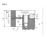
- FIG. 3 shows a second exemplary embodiment of a ring body 1 according to the invention.
- the ring body 1 here has a relation to the first embodiment, different geometry of the web portion 1.3 '.
- the advantage of this embodiment is, in particular, that the production of the web region 1.3 'with comparatively less effort is possible.
- the lower annular surface of the web region 1.3 ' is arranged in the same plane as the clamping surface 1.11, so that here a continuous annular surface can be produced during the turning process.
- the web area 1.3 'in the direction of the axis Z has a geometric extent d 3 ', which is approximately 24 times smaller than the largest geometric extent d 2 of the second ring area 1.2 in the direction of the axis Z (d 3 ' ⁇ 1/24 ⁇ d 2, and d 2 / d 3 ' ⁇ 24).
- FIG. 1 A third embodiment of the invention is shown in FIG.
- the first annular region 1.1 here has slots 1.13, through which the ring body 1 in the direction of the axis Z can adapt particularly to unevenness on the shaft 3, without this leading to unacceptable radial or axial deformations in the range of the angle scaling 2.
- the slotted 1.13 are radially aligned and open to the center of the ring body 1 out.
- recesses it is also possible for recesses to be provided in the first annular region 1.1, which recesses have a closed contour, that is to say elongated holes, for example. In this way, the torsional stiffness about the axis Z can be increased compared to the variant with the open slots 1.13.
- inventions also include bodies in which the slits 1.13, or corresponding recesses with open or closed contour, penetrate not only the first annular region 1.1, but also the web region 1.3.
Landscapes
- Physics & Mathematics (AREA)
- General Physics & Mathematics (AREA)
- Transmission And Conversion Of Sensor Element Output (AREA)
- A Measuring Device Byusing Mechanical Method (AREA)
- Length Measuring Devices With Unspecified Measuring Means (AREA)
Applications Claiming Priority (1)
| Application Number | Priority Date | Filing Date | Title |
|---|---|---|---|
| DE102004056671A DE102004056671A1 (de) | 2004-11-24 | 2004-11-24 | Körper mit einer Winkelskalierung |
Publications (2)
| Publication Number | Publication Date |
|---|---|
| EP1666848A1 true EP1666848A1 (fr) | 2006-06-07 |
| EP1666848B1 EP1666848B1 (fr) | 2013-07-03 |
Family
ID=35262238
Family Applications (1)
| Application Number | Title | Priority Date | Filing Date |
|---|---|---|---|
| EP05016649.5A Active EP1666848B1 (fr) | 2004-11-24 | 2005-08-01 | Objet avec échelle d'angle |
Country Status (4)
| Country | Link |
|---|---|
| US (1) | US7290344B2 (fr) |
| EP (1) | EP1666848B1 (fr) |
| CN (1) | CN1782663B (fr) |
| DE (1) | DE102004056671A1 (fr) |
Cited By (1)
| Publication number | Priority date | Publication date | Assignee | Title |
|---|---|---|---|---|
| EP2019291A1 (fr) * | 2007-07-23 | 2009-01-28 | Dr. Johannes Heidenhain GmbH | Corps doté d'une mise à l'échelle d'angle et son utilisation |
Families Citing this family (5)
| Publication number | Priority date | Publication date | Assignee | Title |
|---|---|---|---|---|
| US7546689B2 (en) * | 2007-07-09 | 2009-06-16 | Hexagon Metrology Ab | Joint for coordinate measurement device |
| JP2010062683A (ja) * | 2008-09-01 | 2010-03-18 | Smk Corp | リモートコントロール送信機 |
| DE202009006254U1 (de) * | 2009-04-29 | 2009-07-16 | Harting Electric Gmbh & Co. Kg | Verbindungselement für elektrische Leiter mit einer Leiterplatte |
| DE102011103739A1 (de) * | 2011-05-31 | 2012-12-06 | Dr. Johannes Heidenhain Gmbh | Verfahren und Vorrichtung zur Maßbandmontage |
| WO2012169582A1 (fr) * | 2011-06-09 | 2012-12-13 | コーデンシ株式会社 | Règle pour codeur rotatif, son procédé de moulage par injection et codeur rotative l'utilisant |
Citations (3)
| Publication number | Priority date | Publication date | Assignee | Title |
|---|---|---|---|---|
| EP0664441A2 (fr) * | 1991-04-26 | 1995-07-26 | Walter Dr. Mehnert | Capteur inductif de position |
| DE19936237A1 (de) * | 1999-08-05 | 2001-02-15 | Heidenhain Gmbh Dr Johannes | Drehgeber mit einer Klemmvorrichtung |
| EP1457762A1 (fr) * | 2003-03-13 | 2004-09-15 | Stegmann GmbH & Co. KG | Dispositif pour mesurer la position, le déplacement ou l'angle de rotation d'un objet |
Family Cites Families (5)
| Publication number | Priority date | Publication date | Assignee | Title |
|---|---|---|---|---|
| DE4021717A1 (de) * | 1990-07-07 | 1992-01-09 | Jost Werke Gmbh | Vorrichtung zum messen des schwenkwinkels zwischen einer sattelzugmaschine und einem an diese angekuppelten sattelanhaenger |
| DE19913262A1 (de) * | 1999-03-24 | 2000-09-28 | Heidenhain Gmbh Dr Johannes | Winkelmeßeinrichtung |
| CN1338615A (zh) * | 2000-02-27 | 2002-03-06 | 湖南航天机电设备与特种材料研究所 | 一种用数字光盘作码盘的传感器 |
| GB0216487D0 (en) * | 2002-07-16 | 2002-08-21 | Renishaw Plc | A rotary scale |
| JP4142942B2 (ja) * | 2002-12-09 | 2008-09-03 | 株式会社ソキア | ロータリエンコーダ |
-
2004
- 2004-11-24 DE DE102004056671A patent/DE102004056671A1/de not_active Withdrawn
-
2005
- 2005-08-01 EP EP05016649.5A patent/EP1666848B1/fr active Active
- 2005-11-23 US US11/286,185 patent/US7290344B2/en active Active
- 2005-11-24 CN CN2005101272540A patent/CN1782663B/zh active Active
Patent Citations (3)
| Publication number | Priority date | Publication date | Assignee | Title |
|---|---|---|---|---|
| EP0664441A2 (fr) * | 1991-04-26 | 1995-07-26 | Walter Dr. Mehnert | Capteur inductif de position |
| DE19936237A1 (de) * | 1999-08-05 | 2001-02-15 | Heidenhain Gmbh Dr Johannes | Drehgeber mit einer Klemmvorrichtung |
| EP1457762A1 (fr) * | 2003-03-13 | 2004-09-15 | Stegmann GmbH & Co. KG | Dispositif pour mesurer la position, le déplacement ou l'angle de rotation d'un objet |
Cited By (2)
| Publication number | Priority date | Publication date | Assignee | Title |
|---|---|---|---|---|
| EP2019291A1 (fr) * | 2007-07-23 | 2009-01-28 | Dr. Johannes Heidenhain GmbH | Corps doté d'une mise à l'échelle d'angle et son utilisation |
| US7707730B2 (en) | 2007-07-23 | 2010-05-04 | Dr. Johannes Heidenhain Gmbh | Body having an angle scale and its use |
Also Published As
| Publication number | Publication date |
|---|---|
| DE102004056671A1 (de) | 2006-06-01 |
| US7290344B2 (en) | 2007-11-06 |
| US20060110885A1 (en) | 2006-05-25 |
| CN1782663B (zh) | 2010-08-11 |
| EP1666848B1 (fr) | 2013-07-03 |
| CN1782663A (zh) | 2006-06-07 |
Similar Documents
| Publication | Publication Date | Title |
|---|---|---|
| EP1903316B1 (fr) | Capteur angulaire et procédé de sa fabrication | |
| EP1643216B1 (fr) | Procédé de fabrication et de montage d'un corps avec une échelle angulair | |
| EP1666848B1 (fr) | Objet avec échelle d'angle | |
| EP2093537A1 (fr) | Système et procédé pour déterminer l'alignement de deux pièces de machine rotatives, l'alignement de deux cylindres creux, ou pour éprouver la rectitude d'u component | |
| EP1757908A1 (fr) | Embrayage et dispositif de mesure d'angle pourvu d'un tel embrayage | |
| EP2638303A1 (fr) | Procédé de montage d'un module porteur de palier à roulement et module porteur de palier à roulement | |
| EP3591344B1 (fr) | Dispositif de mesure pour une broche ou un caroussel | |
| EP2255207B1 (fr) | Systeme de mesure angulaire et procede de fabrication d'un systeme de mesure angulaire | |
| DE19748292A1 (de) | Verfahren zum Anbringen einer Winkelteilung an einer Teilscheibe für Rotationsmeßsysteme sowie Teilscheibe mit Winkelteilung für Rotationsmeßsysteme | |
| EP1322918B1 (fr) | Procede et dispositif pour detecter le mouvement de rotation d'un element monte en rotation autour d'un axe | |
| DE102014203517A1 (de) | Wälzlager mit einer integrierten Winkelmesseinrichtung | |
| DE102006036746B4 (de) | Positionsmesseinrichtung | |
| EP3623102A1 (fr) | Procédé d'orientation d'une broche et machine-outil | |
| DE3706767C2 (fr) | ||
| EP3760981A1 (fr) | Dispositif de mesure d'angle et procédé de fonctionnement d'un dispositif de mesure d'angle | |
| EP3760980A1 (fr) | Dispositif de mesure d'angle | |
| DE69727964T2 (de) | Messapparat zur prüfung der linearen dimension von mechanischen teilen und zugehöriges herstellverfahren | |
| DE202015009568U1 (de) | Kalibrierkörper | |
| DE102018115891A1 (de) | Verfahren zur Herstellung eines Mess-Normals und Mess-Normal | |
| DE4138589A1 (de) | Winkelmessvorrichtung | |
| EP2065684B1 (fr) | Moyen d'ajustement et corps correspondant doté d'une échelle ainsi que procédé d'ajustement | |
| DE102008013378A1 (de) | Winkelmesssystem | |
| DE102005021504A1 (de) | Verfahren zur Herstellung und Montage eines Körpers mit einer Winkelskalierung | |
| EP2975357B1 (fr) | Dispositif doté d'une unité de balayage et d'une aide au montage et procédé de montage de l'unité de balayage | |
| EP3736542B1 (fr) | Dispositif de fixation côté extrémité d'un support s'étendant dans une direction longitudinale doté d'une graduation de mesure destinée à mesurer la position au moins dans une direction longitudinale sur une surface de montage d'un corps de base |
Legal Events
| Date | Code | Title | Description |
|---|---|---|---|
| PUAI | Public reference made under article 153(3) epc to a published international application that has entered the european phase |
Free format text: ORIGINAL CODE: 0009012 |
|
| AK | Designated contracting states |
Kind code of ref document: A1 Designated state(s): AT BE BG CH CY CZ DE DK EE ES FI FR GB GR HU IE IS IT LI LT LU LV MC NL PL PT RO SE SI SK TR |
|
| AX | Request for extension of the european patent |
Extension state: AL BA HR MK YU |
|
| 17P | Request for examination filed |
Effective date: 20061207 |
|
| AKX | Designation fees paid |
Designated state(s): AT BE BG CH CY CZ DE DK EE ES FI FR GB GR HU IE IS IT LI LT LU LV MC NL PL PT RO SE SI SK TR |
|
| GRAP | Despatch of communication of intention to grant a patent |
Free format text: ORIGINAL CODE: EPIDOSNIGR1 |
|
| GRAS | Grant fee paid |
Free format text: ORIGINAL CODE: EPIDOSNIGR3 |
|
| GRAA | (expected) grant |
Free format text: ORIGINAL CODE: 0009210 |
|
| AK | Designated contracting states |
Kind code of ref document: B1 Designated state(s): AT BE BG CH CY CZ DE DK EE ES FI FR GB GR HU IE IS IT LI LT LU LV MC NL PL PT RO SE SI SK TR |
|
| REG | Reference to a national code |
Ref country code: GB Ref legal event code: FG4D Free format text: NOT ENGLISH |
|
| REG | Reference to a national code |
Ref country code: CH Ref legal event code: EP Ref country code: AT Ref legal event code: REF Ref document number: 620034 Country of ref document: AT Kind code of ref document: T Effective date: 20130715 |
|
| REG | Reference to a national code |
Ref country code: IE Ref legal event code: FG4D Free format text: LANGUAGE OF EP DOCUMENT: GERMAN |
|
| REG | Reference to a national code |
Ref country code: DE Ref legal event code: R096 Ref document number: 502005013803 Country of ref document: DE Effective date: 20130829 |
|
| PG25 | Lapsed in a contracting state [announced via postgrant information from national office to epo] |
Ref country code: SI Free format text: LAPSE BECAUSE OF FAILURE TO SUBMIT A TRANSLATION OF THE DESCRIPTION OR TO PAY THE FEE WITHIN THE PRESCRIBED TIME-LIMIT Effective date: 20130703 |
|
| PGFP | Annual fee paid to national office [announced via postgrant information from national office to epo] |
Ref country code: AT Payment date: 20130813 Year of fee payment: 9 |
|
| REG | Reference to a national code |
Ref country code: NL Ref legal event code: VDEP Effective date: 20130703 |
|
| REG | Reference to a national code |
Ref country code: LT Ref legal event code: MG4D |
|
| PG25 | Lapsed in a contracting state [announced via postgrant information from national office to epo] |
Ref country code: LT Free format text: LAPSE BECAUSE OF FAILURE TO SUBMIT A TRANSLATION OF THE DESCRIPTION OR TO PAY THE FEE WITHIN THE PRESCRIBED TIME-LIMIT Effective date: 20130703 Ref country code: IS Free format text: LAPSE BECAUSE OF FAILURE TO SUBMIT A TRANSLATION OF THE DESCRIPTION OR TO PAY THE FEE WITHIN THE PRESCRIBED TIME-LIMIT Effective date: 20131103 Ref country code: CY Free format text: LAPSE BECAUSE OF FAILURE TO SUBMIT A TRANSLATION OF THE DESCRIPTION OR TO PAY THE FEE WITHIN THE PRESCRIBED TIME-LIMIT Effective date: 20130710 Ref country code: SE Free format text: LAPSE BECAUSE OF FAILURE TO SUBMIT A TRANSLATION OF THE DESCRIPTION OR TO PAY THE FEE WITHIN THE PRESCRIBED TIME-LIMIT Effective date: 20130703 Ref country code: PT Free format text: LAPSE BECAUSE OF FAILURE TO SUBMIT A TRANSLATION OF THE DESCRIPTION OR TO PAY THE FEE WITHIN THE PRESCRIBED TIME-LIMIT Effective date: 20131104 |
|
| BERE | Be: lapsed |
Owner name: DR. JOHANNES HEIDENHAIN G.M.B.H. Effective date: 20130831 |
|
| PG25 | Lapsed in a contracting state [announced via postgrant information from national office to epo] |
Ref country code: LV Free format text: LAPSE BECAUSE OF FAILURE TO SUBMIT A TRANSLATION OF THE DESCRIPTION OR TO PAY THE FEE WITHIN THE PRESCRIBED TIME-LIMIT Effective date: 20130703 Ref country code: FI Free format text: LAPSE BECAUSE OF FAILURE TO SUBMIT A TRANSLATION OF THE DESCRIPTION OR TO PAY THE FEE WITHIN THE PRESCRIBED TIME-LIMIT Effective date: 20130703 Ref country code: ES Free format text: LAPSE BECAUSE OF FAILURE TO SUBMIT A TRANSLATION OF THE DESCRIPTION OR TO PAY THE FEE WITHIN THE PRESCRIBED TIME-LIMIT Effective date: 20131014 Ref country code: NL Free format text: LAPSE BECAUSE OF FAILURE TO SUBMIT A TRANSLATION OF THE DESCRIPTION OR TO PAY THE FEE WITHIN THE PRESCRIBED TIME-LIMIT Effective date: 20130703 Ref country code: GR Free format text: LAPSE BECAUSE OF FAILURE TO SUBMIT A TRANSLATION OF THE DESCRIPTION OR TO PAY THE FEE WITHIN THE PRESCRIBED TIME-LIMIT Effective date: 20131004 Ref country code: PL Free format text: LAPSE BECAUSE OF FAILURE TO SUBMIT A TRANSLATION OF THE DESCRIPTION OR TO PAY THE FEE WITHIN THE PRESCRIBED TIME-LIMIT Effective date: 20130703 |
|
| PG25 | Lapsed in a contracting state [announced via postgrant information from national office to epo] |
Ref country code: CY Free format text: LAPSE BECAUSE OF FAILURE TO SUBMIT A TRANSLATION OF THE DESCRIPTION OR TO PAY THE FEE WITHIN THE PRESCRIBED TIME-LIMIT Effective date: 20130703 |
|
| REG | Reference to a national code |
Ref country code: CH Ref legal event code: PL |
|
| PG25 | Lapsed in a contracting state [announced via postgrant information from national office to epo] |
Ref country code: RO Free format text: LAPSE BECAUSE OF FAILURE TO SUBMIT A TRANSLATION OF THE DESCRIPTION OR TO PAY THE FEE WITHIN THE PRESCRIBED TIME-LIMIT Effective date: 20130703 Ref country code: EE Free format text: LAPSE BECAUSE OF FAILURE TO SUBMIT A TRANSLATION OF THE DESCRIPTION OR TO PAY THE FEE WITHIN THE PRESCRIBED TIME-LIMIT Effective date: 20130703 Ref country code: CH Free format text: LAPSE BECAUSE OF NON-PAYMENT OF DUE FEES Effective date: 20130831 Ref country code: LI Free format text: LAPSE BECAUSE OF NON-PAYMENT OF DUE FEES Effective date: 20130831 Ref country code: SK Free format text: LAPSE BECAUSE OF FAILURE TO SUBMIT A TRANSLATION OF THE DESCRIPTION OR TO PAY THE FEE WITHIN THE PRESCRIBED TIME-LIMIT Effective date: 20130703 Ref country code: DK Free format text: LAPSE BECAUSE OF FAILURE TO SUBMIT A TRANSLATION OF THE DESCRIPTION OR TO PAY THE FEE WITHIN THE PRESCRIBED TIME-LIMIT Effective date: 20130703 Ref country code: MC Free format text: LAPSE BECAUSE OF FAILURE TO SUBMIT A TRANSLATION OF THE DESCRIPTION OR TO PAY THE FEE WITHIN THE PRESCRIBED TIME-LIMIT Effective date: 20130703 Ref country code: CZ Free format text: LAPSE BECAUSE OF FAILURE TO SUBMIT A TRANSLATION OF THE DESCRIPTION OR TO PAY THE FEE WITHIN THE PRESCRIBED TIME-LIMIT Effective date: 20130703 |
|
| PLBE | No opposition filed within time limit |
Free format text: ORIGINAL CODE: 0009261 |
|
| STAA | Information on the status of an ep patent application or granted ep patent |
Free format text: STATUS: NO OPPOSITION FILED WITHIN TIME LIMIT |
|
| REG | Reference to a national code |
Ref country code: IE Ref legal event code: MM4A |
|
| REG | Reference to a national code |
Ref country code: FR Ref legal event code: ST Effective date: 20140430 |
|
| PG25 | Lapsed in a contracting state [announced via postgrant information from national office to epo] |
Ref country code: BE Free format text: LAPSE BECAUSE OF NON-PAYMENT OF DUE FEES Effective date: 20130831 Ref country code: IT Free format text: LAPSE BECAUSE OF FAILURE TO SUBMIT A TRANSLATION OF THE DESCRIPTION OR TO PAY THE FEE WITHIN THE PRESCRIBED TIME-LIMIT Effective date: 20130703 |
|
| 26N | No opposition filed |
Effective date: 20140404 |
|
| REG | Reference to a national code |
Ref country code: DE Ref legal event code: R097 Ref document number: 502005013803 Country of ref document: DE Effective date: 20140404 |
|
| PG25 | Lapsed in a contracting state [announced via postgrant information from national office to epo] |
Ref country code: IE Free format text: LAPSE BECAUSE OF NON-PAYMENT OF DUE FEES Effective date: 20130801 |
|
| PG25 | Lapsed in a contracting state [announced via postgrant information from national office to epo] |
Ref country code: FR Free format text: LAPSE BECAUSE OF NON-PAYMENT OF DUE FEES Effective date: 20130903 |
|
| REG | Reference to a national code |
Ref country code: AT Ref legal event code: MM01 Ref document number: 620034 Country of ref document: AT Kind code of ref document: T Effective date: 20140801 |
|
| PG25 | Lapsed in a contracting state [announced via postgrant information from national office to epo] |
Ref country code: AT Free format text: LAPSE BECAUSE OF NON-PAYMENT OF DUE FEES Effective date: 20140801 |
|
| PG25 | Lapsed in a contracting state [announced via postgrant information from national office to epo] |
Ref country code: TR Free format text: LAPSE BECAUSE OF FAILURE TO SUBMIT A TRANSLATION OF THE DESCRIPTION OR TO PAY THE FEE WITHIN THE PRESCRIBED TIME-LIMIT Effective date: 20130703 |
|
| PG25 | Lapsed in a contracting state [announced via postgrant information from national office to epo] |
Ref country code: BG Free format text: LAPSE BECAUSE OF FAILURE TO SUBMIT A TRANSLATION OF THE DESCRIPTION OR TO PAY THE FEE WITHIN THE PRESCRIBED TIME-LIMIT Effective date: 20130703 Ref country code: HU Free format text: LAPSE BECAUSE OF FAILURE TO SUBMIT A TRANSLATION OF THE DESCRIPTION OR TO PAY THE FEE WITHIN THE PRESCRIBED TIME-LIMIT; INVALID AB INITIO Effective date: 20050801 Ref country code: LU Free format text: LAPSE BECAUSE OF NON-PAYMENT OF DUE FEES Effective date: 20130801 |
|
| PGFP | Annual fee paid to national office [announced via postgrant information from national office to epo] |
Ref country code: GB Payment date: 20220822 Year of fee payment: 18 |
|
| PGFP | Annual fee paid to national office [announced via postgrant information from national office to epo] |
Ref country code: DE Payment date: 20230821 Year of fee payment: 19 |
|
| GBPC | Gb: european patent ceased through non-payment of renewal fee |
Effective date: 20230801 |