EP1666848A1 - Body with angular scale - Google Patents
Body with angular scale Download PDFInfo
- Publication number
- EP1666848A1 EP1666848A1 EP05016649A EP05016649A EP1666848A1 EP 1666848 A1 EP1666848 A1 EP 1666848A1 EP 05016649 A EP05016649 A EP 05016649A EP 05016649 A EP05016649 A EP 05016649A EP 1666848 A1 EP1666848 A1 EP 1666848A1
- Authority
- EP
- European Patent Office
- Prior art keywords
- region
- axis
- annular region
- scaling
- angle scaling
- Prior art date
- Legal status (The legal status is an assumption and is not a legal conclusion. Google has not performed a legal analysis and makes no representation as to the accuracy of the status listed.)
- Granted
Links
- 238000000034 method Methods 0.000 claims description 11
- 238000001459 lithography Methods 0.000 claims description 2
- 238000005259 measurement Methods 0.000 description 13
- 238000004519 manufacturing process Methods 0.000 description 6
- 230000003287 optical effect Effects 0.000 description 3
- 230000006866 deterioration Effects 0.000 description 2
- 239000000835 fiber Substances 0.000 description 2
- 230000005484 gravity Effects 0.000 description 2
- 238000000608 laser ablation Methods 0.000 description 2
- 230000007935 neutral effect Effects 0.000 description 2
- 229910000831 Steel Inorganic materials 0.000 description 1
- 238000002679 ablation Methods 0.000 description 1
- 230000001133 acceleration Effects 0.000 description 1
- XAGFODPZIPBFFR-UHFFFAOYSA-N aluminium Chemical compound [Al] XAGFODPZIPBFFR-UHFFFAOYSA-N 0.000 description 1
- 229910052782 aluminium Inorganic materials 0.000 description 1
- 238000005452 bending Methods 0.000 description 1
- 230000001419 dependent effect Effects 0.000 description 1
- 239000000463 material Substances 0.000 description 1
- 230000009467 reduction Effects 0.000 description 1
- 239000010959 steel Substances 0.000 description 1
Images


Classifications
-
- G—PHYSICS
- G01—MEASURING; TESTING
- G01D—MEASURING NOT SPECIALLY ADAPTED FOR A SPECIFIC VARIABLE; ARRANGEMENTS FOR MEASURING TWO OR MORE VARIABLES NOT COVERED IN A SINGLE OTHER SUBCLASS; TARIFF METERING APPARATUS; MEASURING OR TESTING NOT OTHERWISE PROVIDED FOR
- G01D5/00—Mechanical means for transferring the output of a sensing member; Means for converting the output of a sensing member to another variable where the form or nature of the sensing member does not constrain the means for converting; Transducers not specially adapted for a specific variable
- G01D5/26—Mechanical means for transferring the output of a sensing member; Means for converting the output of a sensing member to another variable where the form or nature of the sensing member does not constrain the means for converting; Transducers not specially adapted for a specific variable characterised by optical transfer means, i.e. using infrared, visible, or ultraviolet light
- G01D5/32—Mechanical means for transferring the output of a sensing member; Means for converting the output of a sensing member to another variable where the form or nature of the sensing member does not constrain the means for converting; Transducers not specially adapted for a specific variable characterised by optical transfer means, i.e. using infrared, visible, or ultraviolet light with attenuation or whole or partial obturation of beams of light
- G01D5/34—Mechanical means for transferring the output of a sensing member; Means for converting the output of a sensing member to another variable where the form or nature of the sensing member does not constrain the means for converting; Transducers not specially adapted for a specific variable characterised by optical transfer means, i.e. using infrared, visible, or ultraviolet light with attenuation or whole or partial obturation of beams of light the beams of light being detected by photocells
- G01D5/347—Mechanical means for transferring the output of a sensing member; Means for converting the output of a sensing member to another variable where the form or nature of the sensing member does not constrain the means for converting; Transducers not specially adapted for a specific variable characterised by optical transfer means, i.e. using infrared, visible, or ultraviolet light with attenuation or whole or partial obturation of beams of light the beams of light being detected by photocells using displacement encoding scales
- G01D5/3473—Circular or rotary encoders
-
- G—PHYSICS
- G01—MEASURING; TESTING
- G01D—MEASURING NOT SPECIALLY ADAPTED FOR A SPECIFIC VARIABLE; ARRANGEMENTS FOR MEASURING TWO OR MORE VARIABLES NOT COVERED IN A SINGLE OTHER SUBCLASS; TARIFF METERING APPARATUS; MEASURING OR TESTING NOT OTHERWISE PROVIDED FOR
- G01D5/00—Mechanical means for transferring the output of a sensing member; Means for converting the output of a sensing member to another variable where the form or nature of the sensing member does not constrain the means for converting; Transducers not specially adapted for a specific variable
- G01D5/26—Mechanical means for transferring the output of a sensing member; Means for converting the output of a sensing member to another variable where the form or nature of the sensing member does not constrain the means for converting; Transducers not specially adapted for a specific variable characterised by optical transfer means, i.e. using infrared, visible, or ultraviolet light
- G01D5/32—Mechanical means for transferring the output of a sensing member; Means for converting the output of a sensing member to another variable where the form or nature of the sensing member does not constrain the means for converting; Transducers not specially adapted for a specific variable characterised by optical transfer means, i.e. using infrared, visible, or ultraviolet light with attenuation or whole or partial obturation of beams of light
- G01D5/34—Mechanical means for transferring the output of a sensing member; Means for converting the output of a sensing member to another variable where the form or nature of the sensing member does not constrain the means for converting; Transducers not specially adapted for a specific variable characterised by optical transfer means, i.e. using infrared, visible, or ultraviolet light with attenuation or whole or partial obturation of beams of light the beams of light being detected by photocells
- G01D5/347—Mechanical means for transferring the output of a sensing member; Means for converting the output of a sensing member to another variable where the form or nature of the sensing member does not constrain the means for converting; Transducers not specially adapted for a specific variable characterised by optical transfer means, i.e. using infrared, visible, or ultraviolet light with attenuation or whole or partial obturation of beams of light the beams of light being detected by photocells using displacement encoding scales
Abstract
Description
Die Erfindung betrifft einen Körper mit einer Winkelskalierung gemäß dem Anspruch 1, wie er insbesondere als Träger für eine Maßverkörperung in Winkelmesssystemen einsetzbar ist.The invention relates to a body with an angle scaling according to
Derartige Winkelmesssysteme dienen zur Messung von Drehbewegungen bzw. Drehstellungen eines Maschinenteils, etwa einer Welle, an der dann ein Körper mit einer Winkelskalierung drehfest fixiert ist. Die Winkelskalierung kann beispielsweise eine optische oder eine magnetische Teilung aufweisen, die entsprechend abgetastet werden kann. Dabei wird die Drehbewegung entweder inkremental oder absolut erfasst, der ausgegebene Messwert ist z. B. eine Folge von Zählimpulsen, ein Zählerwert oder ein Codewort. Entsprechende Winkelmesssysteme werden insbesondere in so genannten Pick-and-Place-Maschinen in der Fertigung von elektronischen Bauteilen verwendet, oder in Werkzeugmaschinen für die Messung von rotatorischen Bewegungen eingesetzt. Die Reproduzierbarkeit, bzw. Wiederholbarkeit der Messung von Drehwinkeln von Maschinenteilen auf nur wenige Winkelsekunden genau ist beispielsweise bei den extrem dynamischen Pick-and-Place-Maschinen von großer Bedeutung. Bei Werkzeugmaschinen ist insbesondere die absolute Genauigkeit der Messergebnisse eines Winkelmesssystems entscheidend. Häufig sind Winkelmesssysteme derart ausgestaltet, dass diese keine eigene Lagerung der relativ zueinander drehbaren Bauteile aufweisen.Such angle measuring systems are used to measure rotational movements or rotational positions of a machine part, such as a shaft on which then a body with an angular scaling is fixed in rotation. The angle scaling can have, for example, an optical or a magnetic division, which can be scanned accordingly. The rotational movement is either incremental or absolute, the output measured value is z. B. a sequence of counts, a counter value or a code word. Corresponding angle measuring systems are used in particular in so-called pick-and-place machines in the manufacture of electronic components, or used in machine tools for the measurement of rotational movements. The reproducibility or repeatability of the measurement of angles of rotation of machine parts to just a few angular seconds is of great importance, for example, in the extremely dynamic pick-and-place machines. In machine tools, in particular the absolute accuracy of the measurement results of an angle measuring system is crucial. Frequently, angle measuring systems are designed in such a way that they do not have their own storage of relatively rotatable components.
Die Genauigkeit einer Winkelmessung wird wesentlich durch die Güte der Winkelskalierung, der Formgenauigkeit des Körpers, der die Winkelskalierung trägt, und durch die Rundlauf-Abweichung der Lagerung beeinflusst. Wichtig ist in diesem Zusammenhang auch eine möglichst kleine Exzentrizität des Körpers in Bezug auf die Lagerung. Darüber hinaus müssen insbesondere bei hochdynamische Anwendungen derartige Körper extrem starr mit dem entsprechend Maschineteil verbunden sein und darüber hinaus muss der Körper selbst möglichst verdreh- bzw. torsionssteif ausgestaltet sein, damit präzise Messergebisse erzielbar sind.The accuracy of an angle measurement is significantly affected by the quality of the angle scaling, the dimensional accuracy of the body that carries the angular scaling, and the concentricity of the bearing. Important in this context is the smallest possible eccentricity of the body in relation to the storage. In addition, especially in highly dynamic applications such bodies must be extremely rigidly connected to the corresponding machine part and beyond the body itself must be designed as torsionally or torsionally stiff so that precise measurement results can be achieved.
In dem Prospekt "Winkelmessgeräte" vom Februar 2004 der Firma Heidenhain ist auf der Seite 23 ein Einbau-Winkelmessgerät (Typ ERA bzw. ERM) gezeigt, welches eine Teilungstrommel aufweist, die als ein monolithischer Körper ausgestaltet ist. Ein innerer Ringbereich dieser Teilungstrommel ist zum Verbinden mit einer Welle flanschartig ausgestaltet.In the brochure "Angle Encoders" of February 2004, Heidenhain a built-in angle measuring device (type ERA or ERM) is shown on page 23, which has a pitch drum, which is designed as a monolithic body. An inner ring portion of this pitch drum is designed to be connected to a shaft flange.
Die vorbekannten Vorrichtungen weisen den Nachteil auf, dass vergleichsweise hohe Anforderungen an die Montagefläche, beispielsweise an der Stirnseite einer Welle, und / oder Aufspannfläche des Körpers zu stellen sind, damit keine Verschlechterungen der Messergebnisse, bzw. der Messsignale auftreten.The previously known devices have the disadvantage that comparatively high demands are placed on the mounting surface, for example on the end face of a shaft, and / or clamping surface of the body, so that no deterioration of the measurement results, or the measurement signals occur.
Der Erfindung liegt die Aufgabe zugrunde, einen Körper mit einer Winkelskalierung zur Messung der Drehstellung eines Maschinenteils zu schaffen, welcher sich insbesondere dadurch auszeichnet, dass dieser auch dann überaus gute Messergebnisse liefert, wenn vergleichsweise große Maß-Toleranzen des Maschinenteils bzw. der Aufspannfläche des Körpers vorliegen.The invention has for its object to provide a body with an angular scaling for measuring the rotational position of a machine part, which is characterized in particular by the fact that even then delivers extremely good results when comparatively large dimensional tolerances of the machine part or the clamping surface of the body available.
Diese Aufgabe wird durch einen Körper mit einer Winkelskalierung gemäß dem Anspruch 1 gelöst. Demnach ist der Körper mit einer Winkelskalierung monolithisch ausgebildet und dient zur Messung der Drehstellung bzw. Drehbewegung eines Maschinenteils um eine Achse. Der Körper weist einen ersten Ringbereich und einen zweiten Ringbereich, sowie einen Stegbereich auf. Der erste Ringbereich ist zum Verbinden mit dem Maschinenteil flanschartig ausgestaltet. Am zweiten Ringbereich ist die Winkelskalierung angeordnet. Der Stegbereich befindet sich bezüglich einer radial ausgerichteten Linie zwischen dem ersten Ringbereich und dem zweiten Ringbereich. Dabei weist der Stegbereich in Richtung der Achse eine geometrische Ausdehnung d3 auf, welche mindestens dreimal kleiner ist als die größte geometrische Ausdehnung d2 des zweiten Ringbereichs in Richtung der Achse. Somit gelten die Bedingungen: d3 ≤ 1/3·d2, bzw. d2/d3 ≥ 3.This object is achieved by a body with an angle scaling according to
Es zeigte sich, dass sich mit den erfindungsgemäßen Körpern mit einer Winkelskalierung wesentlich bessere Messergebnisse erzielen lassen als mit herkömmlichen, insbesondere wenn vergleichsweise ungenaue Montageflächen an den Maschinenteilen vorliegen. Es wurde herausgefunden, dass bei konventionellen Körpern Messfehler wegen - wenn auch geringer - Verformungen in axialer Richtung (Planschlag) und in Radialrichtung im Bereich der Winkelskalierung entstehen. Durch die spezielle geometrische Ausgestaltung des Stegbereichs im Verhältnis zum zweiten Ringbereich werden die maßgeblichen Verformungen des zweiten Ringbereiches, welcher die Winkelskalierung trägt, nunmehr bei erfindungsgemäßen Körpern minimiert. Trotz der vorgenommen Veränderungen, insbesondere trotz Querschnittsreduzierungen, wurde überraschenderweise die Torsionssteifigkeit des Körpers selbst nicht in der Weise beeinflusst, dass diese eine Verschlechterung der Messgenauigkeit zur Folge hat. In Summe wurde, wie erwähnt, im Vergleich zu herkömmlichen Winkelmesssystemen die Messgenauigkeit bei relativ grob tolerierten Montageflächen sogar wesentlich verbessert.It has been found that significantly better measurement results can be achieved with the bodies according to the invention having an angle scaling than with conventional ones, especially if comparatively imprecise mounting surfaces are present on the machine parts. It has been found that with conventional bodies, measurement errors occur because of - albeit smaller - deformations in the axial direction (flat lay) and in the radial direction in the range of the angular scaling. Due to the special geometrical configuration of the web region in relation to the second annular region, the relevant deformations of the second annular region, which carries the angular scaling, are now minimized in bodies according to the invention. Despite the changes made, in particular despite cross-sectional reductions, surprisingly, the torsional rigidity of the body itself was not influenced in such a way that this results in a deterioration of the measurement accuracy. In sum, as mentioned, in comparison with conventional angle measuring systems, the measuring accuracy is even substantially improved with relatively roughly tolerated mounting surfaces.
Unter dem Begriff monolithisch ist im Folgenden zu verstehen, dass ein so bezeichneter Körper aus einem Stück besteht, so dass dieser etwa durch einen Drehprozess beispielsweise aus einem Stahl- oder Aluminiumhalbzeug mit vergleichsweise geringem Aufwand gefertigt werden kann.The term monolithic is to be understood below that a so-called body consists of one piece, so that it can be made about a turning process, for example, from a steel or aluminum semi-finished with comparatively little effort.
Der erste Ringbereich ist derart ausgestaltet, dass dieser flanschartig mit einem Maschinenteil, etwa mit einem Wellenende, verbunden werden kann. Flansche ermöglichen eine Montage zweier Maschinenteile unter Aufbringung von axial gerichteten Fixierkräften. Häufig weisen Flansche zu diesem Zweck entlang einer Kreislinie versetzt angeordnete Bohrungen auf durch die Befestigungsmittel, beispielsweise Schrauben, zum Eingriff kommen und so bezüglich des betreffenden Maschinenteils axial gerichtete Halte- oder Fixierkräfte erzeugbar sind.The first annular region is designed in such a way that it can be connected in a flange-like manner to a machine part, for instance to a shaft end. Flanges allow mounting two machine parts under application of axially directed fixing forces. Frequently, flanges for this purpose along a circular line offset holes arranged by the fastening means, such as screws, come into engagement and so with respect to the relevant machine part axially directed holding or fixing forces can be generated.
Die Winkelskalierung kann am zweiten Ringbereich beispielsweise direkt angeordnet bzw. aufgebracht sein, indem etwa die Skalenstriche durch einen Laser-Abladier-Prozess oder durch ein Lithographieverfahren auf den zweiten Ringbereich, also direkt auf den Körper, geschrieben werden. Alternativ dazu kann aber auch die Winkelskalierung in den Körper im zweiten Ringbereich eingeprägt werden. Für beide Varianten bietet sich ein optisches Verfahren zur Abtastung der Winkelskalierung an. In weiterer Ausgestaltung der Erfindung kann am zweiten Ringbereich aber auch eine magnetische Teilung als Winkelskalierung angeordnet sein.The angle scaling can, for example, be arranged or applied directly on the second ring area, for example by writing the scale lines on the second ring area, ie directly on the body, by means of a laser ablation process or by a lithography process. Alternatively, however, the angle scaling can be impressed into the body in the second ring area. For both variants, an optical method for scanning the angle scaling is suitable. In a further embodiment of the invention, however, a magnetic division can also be arranged as an angle scaling on the second ring area.
Die Erfindung umfasst im Übrigen auch Vorrichtungen bei der die Winkelskalierung am zweiten Ringbereich als ein eigenständiges Bauteil angeordnet ist, etwa als ein Maßband.Incidentally, the invention also encompasses devices in which the angular scaling on the second annular region is arranged as an independent component, for example as a measuring tape.
Mit Vorteil weist der Stegbereich in Richtung der Achse eine geometrische Ausdehnung auf, welche mindestens fünfmal kleiner ist (d2/d3 ≥ 5), insbesondere zehnmal kleiner ist (d2/d3 ≥ 10), als die größte geometrische Ausdehnung des zweiten Ringbereichs in Richtung der Achse. Besonders vorteilhaft ist es, wenn der Stegbereich in Richtung der Achse eine geometrische Ausdehnung aufweist, welche mindestens fünfzehnmal kleiner ist, als die größte geometrische Ausdehnung des zweiten Ringbereichs in Richtung der Achse (d2/d3 ≥ 15).Advantageously, the web region has a geometric extension in the direction of the axis which is at least five times smaller (d 2 / d 3 ≥ 5), in particular ten times smaller (d 2 / d 3 ≥ 10), than the largest geometric extent of the second Ring area in the direction of the axis. It is particularly advantageous if the web region has a geometric extension in the direction of the axis which is at least fifteen times smaller than the largest geometric expansion of the second annular region in the direction of the axis (d 2 / d 3 ≥ 15).
Damit der Körper eine ausreichende Steifigkeit, etwa für dessen Fertigungsprozess aufweist, ist mit Vorteil die geometrische Ausdehnung d1 des ersten Ringbereichs größer als die geometrische Ausdehnung d3 des Stegbereichs. Demnach weist also der Stegbereich in Richtung der Achse eine geringere geometrische Ausdehnung d3 auf als die geometrische Ausdehnung des ersten Ringbereichs (d3 < d1).In order for the body to have sufficient rigidity, for example for its production process, the geometric extent d 1 of the first annular region is advantageously greater than the geometric extent d 3 of the web region. Accordingly, the web region in the direction of the axis has a smaller geometric extent d 3 than the geometric extent of the first annular region (d 3 <d 1 ).
In einer bevorzugten Ausgestaltung der Erfindung ist die Winkelskalierung außen auf eine Mantelseite eines zylindrischen, insbesondere eines hohlzylindrischen bzw. ringförmigen, Körpers aufgebracht.In a preferred embodiment of the invention, the angle scaling is externally applied to a shell side of a cylindrical, in particular a hollow cylindrical or annular body.
Besonders vorteilhaft ausgestaltet ist der erfindungsgemäße Körper, wenn dieser als vergleichsweise schlanker Ringkörper ausgeführt ist. Derartige Ringkörper reagieren nämlich durch ihre Biegeweichheit besonders empfindlich gegenüber Ungenauigkeiten der Montagefläche des betreffenden Maschinenteils bzw. gegenüber Ungenauigkeiten der Aufspannfläche des Körpers selbst. Insbesondere bei Ringkörpern bei denen das Verhältnis des Außendurchmessers zum Innendurchmesser kleiner als 5, insbesondere kleiner als 3, mit Vorteil kleiner als 2 ist, ist das erfindungsgemäße Verfahren besonders vorteilhaft.The body according to the invention is particularly advantageous if it is designed as a comparatively slender ring body. Such ring bodies react namely by their bending softness particularly sensitive to inaccuracies in the mounting surface of the machine part or against inaccuracies of the clamping surface of the body itself. Especially in ring bodies where the ratio of the outer diameter to the inner diameter smaller than 5, in particular smaller than 3, advantageously smaller than 2, the method according to the invention is particularly advantageous.
Wenn die Drehstellung eines Maschineteils über eine gesamte oder mehrere Umdrehungen messbar sein soll, weisen mit Vorteil der erste Ringbereich und der zweite Ringbereich, sowie der Stegbereich eine über 360° umlaufende Geometrie auf. Der Ringkörper ist also in diesem Fall als geschlossener Ring ausgeführt.If the rotational position of a machine part is to be measurable over one or more revolutions, the first annular region and the second annular region, as well as the land region, advantageously have a geometry that rotates over 360 °. The ring body is thus designed in this case as a closed ring.
Die Erfindung ist jedoch nicht auf geschlossene Körper beschränkt, welche zylindrisch oder ringförmig ausgestaltet sind. Beispielsweise kann der Körper auch als Ringsegment ausgebildet sein, etwa wenn die Drehstellung eines Maschinenteils nicht über eine volle Umdrehung des Maschinenteils gemessen werden muss.However, the invention is not limited to closed bodies which are cylindrical or annular. For example, the body may also be formed as a ring segment, for example when the rotational position of a machine part does not have to be measured over a full revolution of the machine part.
Die Erfindung weist insbesondere den Vorteil auf, dass die Montagefläche des Maschinenteils, an das der Körper mit der Winkelskalierung angebaut werden soll, eine vergleichsweise große Maßtoleranz, insbesondere in Bezug auf dessen Ebenheit, aufweisen kann, ohne dass die Messergebnisse der Drehstellung des Maschinenteils verschlechtert werden. Hinzu kommt, dass der erfindungsgemäße Körper mit der Winkelskalierung ein geringes Massenträgheitsmoment bei hoher Torsionssteifigkeit aufweist und deshalb für Anwendungen mit hohen Winkelbeschleunigungen besonders geeignet ist. Darüber hinaus ist der entsprechende Körper leicht und mit relativ wenig Aufwand zu fertigen.The invention has the particular advantage that the mounting surface of the machine part to which the body is to be mounted with the angle scaling, a comparatively large dimensional tolerance, in particular with respect to its flatness, may have, without the measurement results of the rotational position of the machine part are deteriorated , In addition, the body according to the invention with the angle scaling has a low mass moment of inertia with high torsional stiffness and is therefore particularly suitable for applications with high angular accelerations is. In addition, the corresponding body is easy to manufacture and with relatively little effort.
Vorteilhafte Ausführungsformen des erfindungsgemäßen Verfahrens sind aus den Maßnahmen in den vom Anspruch 1 abhängigen Ansprüchen zu entnehmen.Advantageous embodiments of the method according to the invention can be taken from the measures in the dependent from
Weitere Vorteile, sowie Einzelheiten des erfindungsgemäßen Körpers mit einer Winkelskalierung ergeben sich aus der nachfolgenden Beschreibung von Ausführungsbeispielen anhand der beiliegenden Figuren.Further advantages, as well as details of the body according to the invention with an angle scaling will become apparent from the following description of exemplary embodiments with reference to the accompanying figures.
Es zeigen die
Figur 1- eine perspektivische Ansicht eines erfindungsgemäßen Körpers mit einer Winkelskalierung,
- Figur 2a
- einen Teilquerschnitt in radialer Richtung durch den Körper im angebauten Zustand, gemäß einem ersten Ausführungsbeispiel,
- Figur 2b
- eine teilweise Seitenansicht auf den Körper mit der Winkelskalierung im angebauten Zustand,
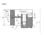
Figur 3- einen Teilquerschnitt in radialer Richtung durch den Körper gemäß einem zweiten Ausführungsbeispiel im angebauten Zustand,
Figur 4- eine perspektivische Ansicht eines erfindungsgemäßen Körpers mit einer Winkelskalierung gemäß einem dritten Ausführungsbeispiel.
- FIG. 1
- a perspective view of a body according to the invention with an angle scaling,
- FIG. 2a
- a partial cross section in the radial direction through the body in the mounted state, according to a first embodiment,
- FIG. 2b
- a partial side view of the body with the angle scaling in the mounted state,
- FIG. 3
- a partial cross section in the radial direction through the body according to a second embodiment in the mounted state,
- FIG. 4
- a perspective view of a body according to the invention with an angle scaling according to a third embodiment.
Gemäß der Figur 1 ist der entsprechende Körper in den vorgestellten Ausführungsbeispielen als Ringkörper 1 ausgestaltet. Dieser Ringkörper 1 weist einen ersten Ringbereich 1.1, einen zweiten Ringbereich 1.2 und einen Stegbereich 1.3 auf, wobei der Stegbereich 1.3 bezüglich einer radial ausgerichteten Linie R zwischen dem ersten Ringbereich 1.1 und dem zweiten Ringbereich 1.2 angeordnet ist. Der erste Ringbereich 1.1 ist flanschartig ausgestaltet und weist Bohrungen 1.12 auf, die entlang einer Kreislinie mit jeweils gleichem Winkelversatz angeordnet sind.According to the figure 1, the corresponding body is designed in the presented embodiments as a
An der äußeren Mantelseite des zweiten Ringbereichs 1.2 ist eine Winkelskalierung 2 angeordnet. In den vorgestellten Ausführungsbeispielen wurde die Winkelskalierung 2 mit einem Laser-Abladier-Prozess direkt auf den Ringkörper aufgebracht ist. Zu diesem Zweck wurde die äußere Mantelseite des zweiten Ringbereichs 1.2 mit einer speziellen Lage beschichtet und dann eine Einzelstrichablation vorgenommen.On the outer shell side of the second ring portion 1.2 an angle scaling 2 is arranged. In the presented embodiments, the angle scaling 2 was applied directly to the ring body with a laser ablation process. For this purpose, the outer shell side of the second ring portion 1.2 was coated with a special layer and then made a single-coat ablation.
Alternativ dazu kann aber auch die eine Winkelskalierung 2 an einer Stirnseite oder an der inneren Mantelseite des zweiten Ringbereichs 1.2 angeordnet sein.Alternatively, however, the one angle scaling 2 can also be arranged on one end face or on the inner shell side of the second ring area 1.2.
Die Winkelskalierung 2 ist so ausgestaltet, dass eine Drehstellung um eine Achse Z des Ringkörpers 1 detektierbar ist, das heißt, dass die Markierungen der Winkelskalierung 2 bei Drehung des Ringkörpers um die Achse Z einen Versatz in Umfangs- bzw. Drehrichtung aufweisen. Im gezeigten Ausführungsbeispiel ist die Winkelskalierung 2 derart ausgestaltet, dass eine optische Abtastung der Winkelskalierung 2 möglich ist. Durch Verwendung einer entsprechenden magnetischen Winkelskalierung bzw. Teilung kann alternativ dazu auch ein magnetisches Abtastprinzip angewendet werden.The angle scaling 2 is designed so that a rotational position about an axis Z of the
Der Ringkörper 1 weist einen Außendurchmesser D und einen Innendurchmesser d auf. Im vorgestellten Ausführungsbeispiel beträgt der Außendurchmesser D = 250 mm und der Innendurchmesser d = 220 mm. Demnach beträgt hier das Verhältnis D/d = 250/220, also 1,14. Der Ringkörper 1 wird mit Hilfe eines Dreh- oder Schleifverfahrens möglichst präzise gefertigt, so dass die Mantelseite eine relativ geringe Rundheitsabweichung aufweist. Gerade bei Ringkörpern 1, welche im Vergleich zum Außendurchmesser D eine relativ große innere Öffnung aufweisen, also einen großen Innendurchmesser d (D/d vergleichsweise klein), sind die minimal fertigbaren Rundheitsabweichungen prinzipiell begrenzt, weil solche Ringkörper 1 durch ihre schlanke Bauweise leicht verformbar sind. So können beispielsweise schon durch das Spannen derartiger Ringkörper 1 in einer Bearbeitungsmaschine störende Durchbiegungen entstehen, welche zu Maßabweichungen des fertigen Ringkörpers 1 führen. Andererseits sind für bestimmte Anwendungen von Winkelmesssystemen, etwa für Pick-and-Place-Maschinen, gerade leichte, und damit auch schlanke, Ringkörper 1 gefordert, damit eine entsprechende Dynamik im Betrieb von z. B. derartiger Pick-and-Place-Maschinen, erreichbar ist.The
In der Figur 2a ist ein Teilquerschnitt in radialer Richtung durch den Ringkörper 1 und ein Maschinenteil, welches in den vorgestellten Ausführungsbeispielen eine Welle 3 ist, gezeigt. Damit die oben genannten Durchbiegungen während der Fertigung des Ringkörpers 1 minimiert werden, ist zur dessen Versteifung der erste Ringbereich 1.1 im Vergleich zum Stegbereich 1.3 dicker ausgeführt. Der Stegbereich 1.3 weist in Richtung der Achse Z also eine geringere geometrische Ausdehnung d3 auf, als die geometrische Ausdehnung d1 des ersten Ringbereichs 1.1.In the figure 2a is a partial cross section in the radial direction through the
Besonders bedeutsam im Hinblick auf genaue Messergebnisse eines entsprechenden Winkelmesssystems ist, dass die geometrische Ausdehnung d3 des Stegbereichs 1.3 in Richtung der Achse Z geringer ist als die des zweiten Ringbereichs 1.2. Die absoluten geometrische Ausdehnung sind im gezeigten Ausführungsbeispiel d1 = 0,8 mm, d2 = 12 mm, d3 = 0,5 mm. Das heißt, dass hier der Stegbereich 1.3 in Richtung der Achse Z eine geometrische Ausdehnung d3 aufweist, welche 24-mal kleiner ist als die größte geometrische Ausdehnung d2 des zweiten Ringbereichs 1.2 in Richtung der Achse Z. Es sind also hier die Bedingungen d3 ≤ 1/24.d2, bzw. d2/d3 ≥ 24 erfüllt. Im gezeigten Ausführungsbeispiel ist überdies der Stegbereich 1.3 der dünnste Bereich des Ringkörpers 1 (d3<d1<d2).Particularly significant with regard to accurate measurement results of a corresponding angle measuring system is that the geometric extent d 3 of the web portion 1.3 in the direction of the axis Z is less than that of the second ring portion 1.2. The absolute geometric extension in the illustrated embodiment d 1 = 0.8 mm, d 2 = 12 mm, d 3 = 0.5 mm. This means that here the web region 1.3 in the direction of the axis Z has a geometric extension d 3 , which is 24 times smaller than the largest geometric extent d 2 of the second ring region 1.2 in the direction of the axis Z. So here are the conditions d 3 ≤ 1/24 2 .d, or d / d 3 ≥ 24 fulfilled. 2 In the embodiment shown, moreover, the web region 1.3 is the thinnest region of the annular body 1 (d 3 <d 1 <d 2 ).
Im ersten Ausführungsbeispiel ist im Übrigen der Stegbereich 1.3 relativ zum ersten Ringbereich 1.1 in Z-Richtung mittig angeordnet. Diese Anordnung ist in der Figur 2a gezeigt, indem die radial ausgerichtete Linie R sowohl den ersten Ringbereich 1.1 als auch den Stegbereich 1.3 mittig durchdringt bzw. die radial ausgerichtete Linie R die Symmetrieachse darstellt. Mit anderen Worten sind der erste Ringbereich 1.1 als auch der Stegbereich 1.3 derart ausgebildet, dass deren Querschnitte bezüglich der radial ausgerichteten Linie R symmetrisch sind. Der Stegbereich 1.3 selbst ist darüber hinaus auch derart ausgebildet, dass dessen Querschnitt alleine eine Geometrie aufweist, die bezüglich der radial ausgerichteten Linie R symmetrisch ist. Diese spezielle Gestaltung des Stegbereichs 1.2 hat sich für die Optimierung der Messergebnisse im Winkelmessgerät als besonders vorteilhaft erwiesen.Incidentally, in the first exemplary embodiment, the web region 1.3 is arranged centrally in the Z direction relative to the first annular region 1.1. This arrangement is shown in FIG. 2a in that the radially oriented line R penetrates centrally both the first ring region 1.1 and the land region 1.3 or the radially oriented line R represents the axis of symmetry. In other words, the first ring portion 1.1 and the web portion 1.3 are formed such that their cross-sections with respect to the radially aligned Line R are symmetrical. Moreover, the web region 1.3 itself is also designed such that its cross-section alone has a geometry which is symmetrical with respect to the radially oriented line R. This special design of the web area 1.2 has proved to be particularly advantageous for optimizing the measurement results in the angle measuring device.
Die Querschnittsfläche des Ringkörpers 1 weist einen Flächenschwerpunkt S auf. Im gezeigten Ausführungsbeispiel kann die Lage des Flächenschwerpunkts S basierend auf den einzelnen Flächenschwerpunkten der im wesentlichen rechteckförmigen Bereiche (erste Ringbereich 1.1, zweiter Ringbereichs 1.2, Stegbereich 1.3) gebildet werden. Dadurch, dass der erste Ringbereich 1.1 die mit Abstand größte Querschnittsfläche aufweist, kommt der Flächenschwerpunkt S in der Nähe der Mitte der Querschnittsfläche des ersten Ringbereichs 1.1 zu liegen.The cross-sectional area of the
Durch den Flächenschwerpunkt S verläuft in radialer Richtung die Ebene N, die durch die Aufspannfläche1.11 gebildet wird. Somit liegt also die Ebene N in der Ebene, in der die neutralen Fasern des Ringkörpers 1 verlaufen. Im Idealfall ist die Winkelskalierung 2 so angeordnet, dass die Ebene N die Winkelskalierung 2 mittig schneidet (Figur 2b).Due to the centroid S in the radial direction, the plane N, which is formed by the Aufspannfläche1.11. Thus, therefore, the plane N lies in the plane in which run the neutral fibers of the
Die Welle 3, deren Drehstellung letztlich ermittelt werden soll, ist um die Achse Z drehbar und weist eine Stirnseite 3.2 auf, die im Rahmen der vorgegebenen Maßtoleranzen zwangsläufig Unebenheiten hat. In der Welle 3 sind Gewindebohrungen 3.1 vorgesehen, welche im gleichen Muster wie die Bohrungen 1.12 des ersten Ringbereichs 1.1 angeordnet sind.The
Bei der Montage des Ringkörpers 1 wird der erste Ringbereich 1.1 bzw. dessen Aufspannfläche 1.11 auf die Stirnseite 3.2 der Welle 3 aufgesetzt. Die Aufspannfläche 1.11 liegt in einer geometrische Ebene, die orthogonal zur Achse Z angeordnet ist, wobei die Bohrungen 1.12 des ersten Ringbereichs 1.1 die Aufspannfläche 1.11 mit senkrechter Richtung (parallel zur Achse Z) durchdringen.During assembly of the
Nach dem Aufsetzen des Ringkörpers 1 erfolgt dessen Zentrierung bezüglich der Welle 3. Sodann wird die Aufspannfläche 1.11 des ersten Ringbereichs 1.1 gegen die Stirnseite 3.2 der Welle 3 durch Anziehen von Schrauben 4, die hier als Befestigungsmittel dienen, gedrückt. Die Bohrungen 1.12 sind parallel zur Achse Z orientiert. Demnach ist also der erste Ringbereich 1.1 derart ausgebildet ist, dass durch die Schrauben 4 der Ringkörper 1 an der Welle 3 fixiert ist, wobei die so erzeugte Fixierkraft in Richtung der Achse Z ausgerichtet ist. Der Ringkörper 1 wird also durch den ersten Ringbereich 1.1, der gleichsam als Flansch ausgebildet ist, mit der Welle 3 verbunden.After placing the
Auf Grund der fertigungsbedingten Unebenheiten sowohl an der Stirnseite 3.2 der Welle 3 als auch an der Aufspannfläche 1.11 des ersten Ringbereichs 1.1 passt sich beim Festziehen der Schrauben 4 der erste Ringbereich 1.1 geometrisch an die besagten Unebenheiten an und verformt sich entsprechend. Diese Verformung erzeugt aber keine nennenswerte radiale oder axiale Verformung des relativ starren zweiten Ringbereichs 1.2 und der an diesem angeordneten Winkelskalierung 2. Es hat sich gezeigt, dass es für die weitere Minimierung der montagebedingten Verformungen des Ringkörpers 1, insbesondere des zweiten Ringbereichs 1.2, von Vorteil ist, wenn die Aufspannfläche 1.11 bzw. die Montagefläche 3.2 in der Ebene N der neutralen Fasern angeordnet ist. Durch den vergleichsweise dünnen Stegbereich 1.3 werden keine unzulässig große radialen Verformungen und auch kein unzulässig großer Planschlag in den Bereich der Winkelskalierung 2 übertragen, wenngleich der Stegbereich 1.3 durchaus vergleichsweise große Deformationen aufweisen kann. Gleichwohl ist der Ringkörper 1 überaus torsionssteif und kann somit in Winkelmessgeräten eingesetzt werden, die in hochdynamischen Maschinen verwendet werden und die hohe Präzisionsforderungen erfüllen.Due to the production-related unevenness both on the end face 3.2 of the
In der Figur 3 ist ein zweites Ausführungsbeispiel eines erfindungsgemäßen Ringkörpers 1 gezeigt. Der Ringkörper 1 weist hier eine gegenüber dem ersten Ausführungsbeispiel unterschiedliche Geometrie des Stegbereiches 1.3' auf. Der Vorteil dieser Ausführungsform liegt insbesondere darin, dass die Herstellung des Stegbereichs 1.3' mit vergleichsweise geringerem Aufwand möglich ist. Die untere Ringfläche des Stegbereichs 1.3' ist in der gleichen Ebene wie die Aufspannfläche 1.11 angeordnet, so dass hier eine durchgehende Ringfläche beim Drehprozess hergestellt werden kann. Lediglich an der oberen Seite des Stegbereichs 1.3' muss eine Rille eingedreht werden, damit schließlich die geringe geometrische Ausdehnung d3' des Stegbereichs 1.3' in Richtung der Achse Z im Vergleich zur geometrische Ausdehnung d2 des zweiten Ringbereichs 1.2 erreicht wird. Im zweiten Ausführungsbeispiel sind die absoluten geometrische Ausdehnung wie folgt bemessen d1 = 0,8 mm, d2 = 12 mm, d3' = 0,5 mm. Das heißt, dass hier der Stegbereich 1.3' in Richtung der Achse Z eine geometrische Ausdehnung d3' aufweist, welche etwa 24-mal kleiner ist als die größte geometrische Ausdehnung d2 des zweiten Ringbereichs 1.2 in Richtung der Achse Z (d3' ≤ 1/24·d2, bzw. d2/d3' ≥ 24).FIG. 3 shows a second exemplary embodiment of a
Ein drittes Ausführungsbeispiel der Erfindung ist in der Figur 4 dargestellt. Der erste Ringbereich 1.1 weist hier Schlitze 1.13 auf, durch welche sich der Ringkörper 1 in Richtung der Achse Z besonders an Unebenheiten auf der Welle 3 anpassen kann, ohne dass dies zu unzulässigen radialen oder axialen Verformungen im Bereich der Winkelskalierung 2 führt. Im gezeigten dritten Ausführungsbeispiel gemäß der Figur 4 sind die Schlitzte 1.13 radial ausgerichtet und zum Mittelpunkt des Ringkörpers 1 hin offen. Alternativ dazu können aber auch im ersten Ringbereich 1.1 Ausnehmungen vorgesehen sein, welche eine geschlossene Kontur aufweisen, also beispielsweise Langlöcher. Auf diese Weise kann die Torsionssteifigkeit um die Achse Z gegenüber der Variante mit den offenen Schlitzen 1.13 erhöht werden.A third embodiment of the invention is shown in FIG. The first annular region 1.1 here has slots 1.13, through which the
Ferner umfasst die Erfindungen auch Körper, bei denen die Schlitze 1.13 , bzw. entsprechende Ausnehmungen mit offener oder geschlossener Kontur, nicht nur den ersten Ringbereich 1.1 durchdringen, sondern auch den Stegbereich 1.3.Furthermore, the inventions also include bodies in which the slits 1.13, or corresponding recesses with open or closed contour, penetrate not only the first annular region 1.1, but also the web region 1.3.
Claims (14)
der Stegbereich (1.3, 1.3') zwischen dem ersten Ringbereich (1.1) und dem zweiten Ringbereich (1.2) angeordnet ist, und der Stegbereich (1.3, 1.3') in Richtung der Achse (Z) eine geometrische Ausdehnung (d3, d3') aufweist, welche mindestens dreimal kleiner ist als die größte geometrische Ausdehnung (d2) des zweiten Ringbereichs (1.2) in Richtung der Achse (Z).Body (1) with an angular scale (2) which is rotatable about an axis (Z) for measuring the rotational position of a machine part (3), said body (1) being monolithic and
the web region (1.3, 1.3 ') is arranged between the first annular region (1.1) and the second annular region (1.2), and the web region (1.3, 1.3') in the direction of the axis (Z) has a geometric extension (d 3 , d 3 ') which is at least three times smaller than the largest geometric extent (d 2 ) of the second annular region (1.2) in the direction of the axis (Z).
Applications Claiming Priority (1)
| Application Number | Priority Date | Filing Date | Title |
|---|---|---|---|
| DE102004056671A DE102004056671A1 (en) | 2004-11-24 | 2004-11-24 | Body with an angle scaling |
Publications (2)
| Publication Number | Publication Date |
|---|---|
| EP1666848A1 true EP1666848A1 (en) | 2006-06-07 |
| EP1666848B1 EP1666848B1 (en) | 2013-07-03 |
Family
ID=35262238
Family Applications (1)
| Application Number | Title | Priority Date | Filing Date |
|---|---|---|---|
| EP05016649.5A Active EP1666848B1 (en) | 2004-11-24 | 2005-08-01 | Body with angular scale |
Country Status (4)
| Country | Link |
|---|---|
| US (1) | US7290344B2 (en) |
| EP (1) | EP1666848B1 (en) |
| CN (1) | CN1782663B (en) |
| DE (1) | DE102004056671A1 (en) |
Cited By (1)
| Publication number | Priority date | Publication date | Assignee | Title |
|---|---|---|---|---|
| EP2019291A1 (en) * | 2007-07-23 | 2009-01-28 | Dr. Johannes Heidenhain GmbH | Body with angle scaling and its use |
Families Citing this family (5)
| Publication number | Priority date | Publication date | Assignee | Title |
|---|---|---|---|---|
| US7546689B2 (en) * | 2007-07-09 | 2009-06-16 | Hexagon Metrology Ab | Joint for coordinate measurement device |
| JP2010062683A (en) * | 2008-09-01 | 2010-03-18 | Smk Corp | Remote control transmitter |
| DE202009006254U1 (en) | 2009-04-29 | 2009-07-16 | Harting Electric Gmbh & Co. Kg | Connecting element for electrical conductors with a printed circuit board |
| DE102011103739A1 (en) * | 2011-05-31 | 2012-12-06 | Dr. Johannes Heidenhain Gmbh | Method and device for measuring tape assembly |
| CN103620349B (en) * | 2011-06-09 | 2017-05-24 | Kodenshi株式会社 | Scale for rotary encoder, method of injection-molding same, and rotary encoder using same |
Citations (3)
| Publication number | Priority date | Publication date | Assignee | Title |
|---|---|---|---|---|
| EP0664441A2 (en) * | 1991-04-26 | 1995-07-26 | Walter Dr. Mehnert | Inductive position sensor |
| DE19936237A1 (en) * | 1999-08-05 | 2001-02-15 | Heidenhain Gmbh Dr Johannes | Rotation sensor mount has simple clamp arrangement |
| EP1457762A1 (en) * | 2003-03-13 | 2004-09-15 | Stegmann GmbH & Co. KG | Device for measuring the position, the displacement or the rotational angle of an object |
Family Cites Families (5)
| Publication number | Priority date | Publication date | Assignee | Title |
|---|---|---|---|---|
| DE4021717A1 (en) * | 1990-07-07 | 1992-01-09 | Jost Werke Gmbh | Measuring pivot angle between tractor and trailer of articulated lorry - using measurement wheel and angle transducer on coupling plate |
| DE19913262A1 (en) * | 1999-03-24 | 2000-09-28 | Heidenhain Gmbh Dr Johannes | Angle measuring equipment for measuring rotations of shaft or as rotation shaft encoders has part of connecting cable fastened by holder on housing while holder may release tension of connecting cable |
| CN1338615A (en) * | 2000-02-27 | 2002-03-06 | 湖南航天机电设备与特种材料研究所 | Sensor using digitalized optical disk as code disk |
| GB0216487D0 (en) * | 2002-07-16 | 2002-08-21 | Renishaw Plc | A rotary scale |
| JP4142942B2 (en) * | 2002-12-09 | 2008-09-03 | 株式会社ソキア | Rotary encoder |
-
2004
- 2004-11-24 DE DE102004056671A patent/DE102004056671A1/en not_active Withdrawn
-
2005
- 2005-08-01 EP EP05016649.5A patent/EP1666848B1/en active Active
- 2005-11-23 US US11/286,185 patent/US7290344B2/en active Active
- 2005-11-24 CN CN2005101272540A patent/CN1782663B/en active Active
Patent Citations (3)
| Publication number | Priority date | Publication date | Assignee | Title |
|---|---|---|---|---|
| EP0664441A2 (en) * | 1991-04-26 | 1995-07-26 | Walter Dr. Mehnert | Inductive position sensor |
| DE19936237A1 (en) * | 1999-08-05 | 2001-02-15 | Heidenhain Gmbh Dr Johannes | Rotation sensor mount has simple clamp arrangement |
| EP1457762A1 (en) * | 2003-03-13 | 2004-09-15 | Stegmann GmbH & Co. KG | Device for measuring the position, the displacement or the rotational angle of an object |
Cited By (2)
| Publication number | Priority date | Publication date | Assignee | Title |
|---|---|---|---|---|
| EP2019291A1 (en) * | 2007-07-23 | 2009-01-28 | Dr. Johannes Heidenhain GmbH | Body with angle scaling and its use |
| US7707730B2 (en) | 2007-07-23 | 2010-05-04 | Dr. Johannes Heidenhain Gmbh | Body having an angle scale and its use |
Also Published As
| Publication number | Publication date |
|---|---|
| US7290344B2 (en) | 2007-11-06 |
| DE102004056671A1 (en) | 2006-06-01 |
| CN1782663B (en) | 2010-08-11 |
| CN1782663A (en) | 2006-06-07 |
| EP1666848B1 (en) | 2013-07-03 |
| US20060110885A1 (en) | 2006-05-25 |
Similar Documents
| Publication | Publication Date | Title |
|---|---|---|
| EP1903316B1 (en) | Rotary encoder and method of its manufacture | |
| EP1666848B1 (en) | Body with angular scale | |
| EP1643216A1 (en) | Method for the fabrication and mounting of a body with an angular scale | |
| EP2093537A1 (en) | Process and device for the determination of the alignment of two rotatable machine parts, of the alignment of two hollow cylindrical machine parts, or for the examination of a component for straightness | |
| DE102006020067A1 (en) | Clutch and angle measuring device with this coupling | |
| WO2012062640A1 (en) | Method for mounting an anti-friction bearing carrier module, and anti-friction bearing carrier module | |
| EP3591344B1 (en) | Measuring device for a spindle or a rotary table | |
| EP2255207B1 (en) | Angle measuring system and method for producing an angle measuring system | |
| EP0913669A2 (en) | Procedure to provide an angle measuring scale on a disc and rotation measuring devices using same | |
| EP1322918B1 (en) | Device and method for detecting the rotational movement of an element rotatably mounted about an axis | |
| DE102014203517A1 (en) | Rolling bearings with an integrated angle measuring device | |
| DE102006036746B4 (en) | Position measuring device | |
| DE3706767C2 (en) | ||
| EP3760981A1 (en) | Angle measuring device and method for operating an angle measuring device | |
| EP3760980A1 (en) | Angle measuring equipment | |
| DE69727964T2 (en) | MEASURING APPARATUS FOR CHECKING THE LINEAR DIMENSION OF MECHANICAL PARTS AND RELATED MANUFACTURING METHOD | |
| DE202015009568U1 (en) | calibration | |
| DE102018115891A1 (en) | Process for producing a measurement standard and measurement standard | |
| DE4138589A1 (en) | ANGLE MEASURING DEVICE | |
| EP3623102A1 (en) | Method for aligning a spindle and machine tool | |
| EP2065684B1 (en) | Adjustment device and corresponding bodies with scaling and method for adjusting | |
| DE102005021504A1 (en) | Body manufacturing and mounting method for angle measuring system, involves applying angle scaling on body adjusted based on carrier device, and mounting body on machine part, so that distances between markings and point are same and large | |
| EP2975357B1 (en) | Device comprising a scanning unit and an assembly aid and method for assembling the scanning unit | |
| EP3736542B1 (en) | Assembly for fixing an end of a support extending in a longitudinal direction with a measurement point for position measurement at least in a longitudinal direction on an attachment face of a carrier | |
| DE102008013378A1 (en) | Angle measuring system |
Legal Events
| Date | Code | Title | Description |
|---|---|---|---|
| PUAI | Public reference made under article 153(3) epc to a published international application that has entered the european phase |
Free format text: ORIGINAL CODE: 0009012 |
|
| AK | Designated contracting states |
Kind code of ref document: A1 Designated state(s): AT BE BG CH CY CZ DE DK EE ES FI FR GB GR HU IE IS IT LI LT LU LV MC NL PL PT RO SE SI SK TR |
|
| AX | Request for extension of the european patent |
Extension state: AL BA HR MK YU |
|
| 17P | Request for examination filed |
Effective date: 20061207 |
|
| AKX | Designation fees paid |
Designated state(s): AT BE BG CH CY CZ DE DK EE ES FI FR GB GR HU IE IS IT LI LT LU LV MC NL PL PT RO SE SI SK TR |
|
| GRAP | Despatch of communication of intention to grant a patent |
Free format text: ORIGINAL CODE: EPIDOSNIGR1 |
|
| GRAS | Grant fee paid |
Free format text: ORIGINAL CODE: EPIDOSNIGR3 |
|
| GRAA | (expected) grant |
Free format text: ORIGINAL CODE: 0009210 |
|
| AK | Designated contracting states |
Kind code of ref document: B1 Designated state(s): AT BE BG CH CY CZ DE DK EE ES FI FR GB GR HU IE IS IT LI LT LU LV MC NL PL PT RO SE SI SK TR |
|
| REG | Reference to a national code |
Ref country code: GB Ref legal event code: FG4D Free format text: NOT ENGLISH |
|
| REG | Reference to a national code |
Ref country code: CH Ref legal event code: EP Ref country code: AT Ref legal event code: REF Ref document number: 620034 Country of ref document: AT Kind code of ref document: T Effective date: 20130715 |
|
| REG | Reference to a national code |
Ref country code: IE Ref legal event code: FG4D Free format text: LANGUAGE OF EP DOCUMENT: GERMAN |
|
| REG | Reference to a national code |
Ref country code: DE Ref legal event code: R096 Ref document number: 502005013803 Country of ref document: DE Effective date: 20130829 |
|
| PG25 | Lapsed in a contracting state [announced via postgrant information from national office to epo] |
Ref country code: SI Free format text: LAPSE BECAUSE OF FAILURE TO SUBMIT A TRANSLATION OF THE DESCRIPTION OR TO PAY THE FEE WITHIN THE PRESCRIBED TIME-LIMIT Effective date: 20130703 |
|
| PGFP | Annual fee paid to national office [announced via postgrant information from national office to epo] |
Ref country code: AT Payment date: 20130813 Year of fee payment: 9 |
|
| REG | Reference to a national code |
Ref country code: NL Ref legal event code: VDEP Effective date: 20130703 |
|
| REG | Reference to a national code |
Ref country code: LT Ref legal event code: MG4D |
|
| PG25 | Lapsed in a contracting state [announced via postgrant information from national office to epo] |
Ref country code: LT Free format text: LAPSE BECAUSE OF FAILURE TO SUBMIT A TRANSLATION OF THE DESCRIPTION OR TO PAY THE FEE WITHIN THE PRESCRIBED TIME-LIMIT Effective date: 20130703 Ref country code: IS Free format text: LAPSE BECAUSE OF FAILURE TO SUBMIT A TRANSLATION OF THE DESCRIPTION OR TO PAY THE FEE WITHIN THE PRESCRIBED TIME-LIMIT Effective date: 20131103 Ref country code: CY Free format text: LAPSE BECAUSE OF FAILURE TO SUBMIT A TRANSLATION OF THE DESCRIPTION OR TO PAY THE FEE WITHIN THE PRESCRIBED TIME-LIMIT Effective date: 20130710 Ref country code: SE Free format text: LAPSE BECAUSE OF FAILURE TO SUBMIT A TRANSLATION OF THE DESCRIPTION OR TO PAY THE FEE WITHIN THE PRESCRIBED TIME-LIMIT Effective date: 20130703 Ref country code: PT Free format text: LAPSE BECAUSE OF FAILURE TO SUBMIT A TRANSLATION OF THE DESCRIPTION OR TO PAY THE FEE WITHIN THE PRESCRIBED TIME-LIMIT Effective date: 20131104 |
|
| BERE | Be: lapsed |
Owner name: DR. JOHANNES HEIDENHAIN G.M.B.H. Effective date: 20130831 |
|
| PG25 | Lapsed in a contracting state [announced via postgrant information from national office to epo] |
Ref country code: LV Free format text: LAPSE BECAUSE OF FAILURE TO SUBMIT A TRANSLATION OF THE DESCRIPTION OR TO PAY THE FEE WITHIN THE PRESCRIBED TIME-LIMIT Effective date: 20130703 Ref country code: FI Free format text: LAPSE BECAUSE OF FAILURE TO SUBMIT A TRANSLATION OF THE DESCRIPTION OR TO PAY THE FEE WITHIN THE PRESCRIBED TIME-LIMIT Effective date: 20130703 Ref country code: ES Free format text: LAPSE BECAUSE OF FAILURE TO SUBMIT A TRANSLATION OF THE DESCRIPTION OR TO PAY THE FEE WITHIN THE PRESCRIBED TIME-LIMIT Effective date: 20131014 Ref country code: NL Free format text: LAPSE BECAUSE OF FAILURE TO SUBMIT A TRANSLATION OF THE DESCRIPTION OR TO PAY THE FEE WITHIN THE PRESCRIBED TIME-LIMIT Effective date: 20130703 Ref country code: GR Free format text: LAPSE BECAUSE OF FAILURE TO SUBMIT A TRANSLATION OF THE DESCRIPTION OR TO PAY THE FEE WITHIN THE PRESCRIBED TIME-LIMIT Effective date: 20131004 Ref country code: PL Free format text: LAPSE BECAUSE OF FAILURE TO SUBMIT A TRANSLATION OF THE DESCRIPTION OR TO PAY THE FEE WITHIN THE PRESCRIBED TIME-LIMIT Effective date: 20130703 |
|
| PG25 | Lapsed in a contracting state [announced via postgrant information from national office to epo] |
Ref country code: CY Free format text: LAPSE BECAUSE OF FAILURE TO SUBMIT A TRANSLATION OF THE DESCRIPTION OR TO PAY THE FEE WITHIN THE PRESCRIBED TIME-LIMIT Effective date: 20130703 |
|
| REG | Reference to a national code |
Ref country code: CH Ref legal event code: PL |
|
| PG25 | Lapsed in a contracting state [announced via postgrant information from national office to epo] |
Ref country code: RO Free format text: LAPSE BECAUSE OF FAILURE TO SUBMIT A TRANSLATION OF THE DESCRIPTION OR TO PAY THE FEE WITHIN THE PRESCRIBED TIME-LIMIT Effective date: 20130703 Ref country code: EE Free format text: LAPSE BECAUSE OF FAILURE TO SUBMIT A TRANSLATION OF THE DESCRIPTION OR TO PAY THE FEE WITHIN THE PRESCRIBED TIME-LIMIT Effective date: 20130703 Ref country code: CH Free format text: LAPSE BECAUSE OF NON-PAYMENT OF DUE FEES Effective date: 20130831 Ref country code: LI Free format text: LAPSE BECAUSE OF NON-PAYMENT OF DUE FEES Effective date: 20130831 Ref country code: SK Free format text: LAPSE BECAUSE OF FAILURE TO SUBMIT A TRANSLATION OF THE DESCRIPTION OR TO PAY THE FEE WITHIN THE PRESCRIBED TIME-LIMIT Effective date: 20130703 Ref country code: DK Free format text: LAPSE BECAUSE OF FAILURE TO SUBMIT A TRANSLATION OF THE DESCRIPTION OR TO PAY THE FEE WITHIN THE PRESCRIBED TIME-LIMIT Effective date: 20130703 Ref country code: MC Free format text: LAPSE BECAUSE OF FAILURE TO SUBMIT A TRANSLATION OF THE DESCRIPTION OR TO PAY THE FEE WITHIN THE PRESCRIBED TIME-LIMIT Effective date: 20130703 Ref country code: CZ Free format text: LAPSE BECAUSE OF FAILURE TO SUBMIT A TRANSLATION OF THE DESCRIPTION OR TO PAY THE FEE WITHIN THE PRESCRIBED TIME-LIMIT Effective date: 20130703 |
|
| PLBE | No opposition filed within time limit |
Free format text: ORIGINAL CODE: 0009261 |
|
| STAA | Information on the status of an ep patent application or granted ep patent |
Free format text: STATUS: NO OPPOSITION FILED WITHIN TIME LIMIT |
|
| REG | Reference to a national code |
Ref country code: IE Ref legal event code: MM4A |
|
| REG | Reference to a national code |
Ref country code: FR Ref legal event code: ST Effective date: 20140430 |
|
| PG25 | Lapsed in a contracting state [announced via postgrant information from national office to epo] |
Ref country code: BE Free format text: LAPSE BECAUSE OF NON-PAYMENT OF DUE FEES Effective date: 20130831 Ref country code: IT Free format text: LAPSE BECAUSE OF FAILURE TO SUBMIT A TRANSLATION OF THE DESCRIPTION OR TO PAY THE FEE WITHIN THE PRESCRIBED TIME-LIMIT Effective date: 20130703 |
|
| 26N | No opposition filed |
Effective date: 20140404 |
|
| REG | Reference to a national code |
Ref country code: DE Ref legal event code: R097 Ref document number: 502005013803 Country of ref document: DE Effective date: 20140404 |
|
| PG25 | Lapsed in a contracting state [announced via postgrant information from national office to epo] |
Ref country code: IE Free format text: LAPSE BECAUSE OF NON-PAYMENT OF DUE FEES Effective date: 20130801 |
|
| PG25 | Lapsed in a contracting state [announced via postgrant information from national office to epo] |
Ref country code: FR Free format text: LAPSE BECAUSE OF NON-PAYMENT OF DUE FEES Effective date: 20130903 |
|
| REG | Reference to a national code |
Ref country code: AT Ref legal event code: MM01 Ref document number: 620034 Country of ref document: AT Kind code of ref document: T Effective date: 20140801 |
|
| PG25 | Lapsed in a contracting state [announced via postgrant information from national office to epo] |
Ref country code: AT Free format text: LAPSE BECAUSE OF NON-PAYMENT OF DUE FEES Effective date: 20140801 |
|
| PG25 | Lapsed in a contracting state [announced via postgrant information from national office to epo] |
Ref country code: TR Free format text: LAPSE BECAUSE OF FAILURE TO SUBMIT A TRANSLATION OF THE DESCRIPTION OR TO PAY THE FEE WITHIN THE PRESCRIBED TIME-LIMIT Effective date: 20130703 |
|
| PG25 | Lapsed in a contracting state [announced via postgrant information from national office to epo] |
Ref country code: BG Free format text: LAPSE BECAUSE OF FAILURE TO SUBMIT A TRANSLATION OF THE DESCRIPTION OR TO PAY THE FEE WITHIN THE PRESCRIBED TIME-LIMIT Effective date: 20130703 Ref country code: HU Free format text: LAPSE BECAUSE OF FAILURE TO SUBMIT A TRANSLATION OF THE DESCRIPTION OR TO PAY THE FEE WITHIN THE PRESCRIBED TIME-LIMIT; INVALID AB INITIO Effective date: 20050801 Ref country code: LU Free format text: LAPSE BECAUSE OF NON-PAYMENT OF DUE FEES Effective date: 20130801 |
|
| PGFP | Annual fee paid to national office [announced via postgrant information from national office to epo] |
Ref country code: GB Payment date: 20220822 Year of fee payment: 18 |
|
| PGFP | Annual fee paid to national office [announced via postgrant information from national office to epo] |
Ref country code: DE Payment date: 20230821 Year of fee payment: 19 |
|
| GBPC | Gb: european patent ceased through non-payment of renewal fee |
Effective date: 20230801 |