EP1666813A1 - Multi-type air conditioner and method to distribute oil uniformly - Google Patents
Multi-type air conditioner and method to distribute oil uniformly Download PDFInfo
- Publication number
- EP1666813A1 EP1666813A1 EP05024435A EP05024435A EP1666813A1 EP 1666813 A1 EP1666813 A1 EP 1666813A1 EP 05024435 A EP05024435 A EP 05024435A EP 05024435 A EP05024435 A EP 05024435A EP 1666813 A1 EP1666813 A1 EP 1666813A1
- Authority
- EP
- European Patent Office
- Prior art keywords
- compressors
- oil
- air conditioner
- type air
- refrigerant
- Prior art date
- Legal status (The legal status is an assumption and is not a legal conclusion. Google has not performed a legal analysis and makes no representation as to the accuracy of the status listed.)
- Withdrawn
Links
Images




Classifications
-
- F—MECHANICAL ENGINEERING; LIGHTING; HEATING; WEAPONS; BLASTING
- F25—REFRIGERATION OR COOLING; COMBINED HEATING AND REFRIGERATION SYSTEMS; HEAT PUMP SYSTEMS; MANUFACTURE OR STORAGE OF ICE; LIQUEFACTION SOLIDIFICATION OF GASES
- F25B—REFRIGERATION MACHINES, PLANTS OR SYSTEMS; COMBINED HEATING AND REFRIGERATION SYSTEMS; HEAT PUMP SYSTEMS
- F25B49/00—Arrangement or mounting of control or safety devices
-
- F—MECHANICAL ENGINEERING; LIGHTING; HEATING; WEAPONS; BLASTING
- F25—REFRIGERATION OR COOLING; COMBINED HEATING AND REFRIGERATION SYSTEMS; HEAT PUMP SYSTEMS; MANUFACTURE OR STORAGE OF ICE; LIQUEFACTION SOLIDIFICATION OF GASES
- F25B—REFRIGERATION MACHINES, PLANTS OR SYSTEMS; COMBINED HEATING AND REFRIGERATION SYSTEMS; HEAT PUMP SYSTEMS
- F25B31/00—Compressor arrangements
- F25B31/002—Lubrication
-
- F—MECHANICAL ENGINEERING; LIGHTING; HEATING; WEAPONS; BLASTING
- F25—REFRIGERATION OR COOLING; COMBINED HEATING AND REFRIGERATION SYSTEMS; HEAT PUMP SYSTEMS; MANUFACTURE OR STORAGE OF ICE; LIQUEFACTION SOLIDIFICATION OF GASES
- F25B—REFRIGERATION MACHINES, PLANTS OR SYSTEMS; COMBINED HEATING AND REFRIGERATION SYSTEMS; HEAT PUMP SYSTEMS
- F25B43/00—Arrangements for separating or purifying gases or liquids; Arrangements for vaporising the residuum of liquid refrigerant, e.g. by heat
-
- F—MECHANICAL ENGINEERING; LIGHTING; HEATING; WEAPONS; BLASTING
- F25—REFRIGERATION OR COOLING; COMBINED HEATING AND REFRIGERATION SYSTEMS; HEAT PUMP SYSTEMS; MANUFACTURE OR STORAGE OF ICE; LIQUEFACTION SOLIDIFICATION OF GASES
- F25B—REFRIGERATION MACHINES, PLANTS OR SYSTEMS; COMBINED HEATING AND REFRIGERATION SYSTEMS; HEAT PUMP SYSTEMS
- F25B13/00—Compression machines, plants or systems, with reversible cycle
-
- F—MECHANICAL ENGINEERING; LIGHTING; HEATING; WEAPONS; BLASTING
- F25—REFRIGERATION OR COOLING; COMBINED HEATING AND REFRIGERATION SYSTEMS; HEAT PUMP SYSTEMS; MANUFACTURE OR STORAGE OF ICE; LIQUEFACTION SOLIDIFICATION OF GASES
- F25B—REFRIGERATION MACHINES, PLANTS OR SYSTEMS; COMBINED HEATING AND REFRIGERATION SYSTEMS; HEAT PUMP SYSTEMS
- F25B2313/00—Compression machines, plants or systems with reversible cycle not otherwise provided for
- F25B2313/006—Compression machines, plants or systems with reversible cycle not otherwise provided for two pipes connecting the outdoor side to the indoor side with multiple indoor units
-
- F—MECHANICAL ENGINEERING; LIGHTING; HEATING; WEAPONS; BLASTING
- F25—REFRIGERATION OR COOLING; COMBINED HEATING AND REFRIGERATION SYSTEMS; HEAT PUMP SYSTEMS; MANUFACTURE OR STORAGE OF ICE; LIQUEFACTION SOLIDIFICATION OF GASES
- F25B—REFRIGERATION MACHINES, PLANTS OR SYSTEMS; COMBINED HEATING AND REFRIGERATION SYSTEMS; HEAT PUMP SYSTEMS
- F25B2313/00—Compression machines, plants or systems with reversible cycle not otherwise provided for
- F25B2313/025—Compression machines, plants or systems with reversible cycle not otherwise provided for using multiple outdoor units
- F25B2313/0253—Compression machines, plants or systems with reversible cycle not otherwise provided for using multiple outdoor units in parallel arrangements
-
- F—MECHANICAL ENGINEERING; LIGHTING; HEATING; WEAPONS; BLASTING
- F25—REFRIGERATION OR COOLING; COMBINED HEATING AND REFRIGERATION SYSTEMS; HEAT PUMP SYSTEMS; MANUFACTURE OR STORAGE OF ICE; LIQUEFACTION SOLIDIFICATION OF GASES
- F25B—REFRIGERATION MACHINES, PLANTS OR SYSTEMS; COMBINED HEATING AND REFRIGERATION SYSTEMS; HEAT PUMP SYSTEMS
- F25B2400/00—Component parts or details not otherwise provided for in this subclass
- F25B2400/07—Details of compressors or related parts
- F25B2400/075—Details of compressors or related parts with parallel compressors
-
- F—MECHANICAL ENGINEERING; LIGHTING; HEATING; WEAPONS; BLASTING
- F25—REFRIGERATION OR COOLING; COMBINED HEATING AND REFRIGERATION SYSTEMS; HEAT PUMP SYSTEMS; MANUFACTURE OR STORAGE OF ICE; LIQUEFACTION SOLIDIFICATION OF GASES
- F25B—REFRIGERATION MACHINES, PLANTS OR SYSTEMS; COMBINED HEATING AND REFRIGERATION SYSTEMS; HEAT PUMP SYSTEMS
- F25B2500/00—Problems to be solved
- F25B2500/01—Geometry problems, e.g. for reducing size
-
- F—MECHANICAL ENGINEERING; LIGHTING; HEATING; WEAPONS; BLASTING
- F25—REFRIGERATION OR COOLING; COMBINED HEATING AND REFRIGERATION SYSTEMS; HEAT PUMP SYSTEMS; MANUFACTURE OR STORAGE OF ICE; LIQUEFACTION SOLIDIFICATION OF GASES
- F25B—REFRIGERATION MACHINES, PLANTS OR SYSTEMS; COMBINED HEATING AND REFRIGERATION SYSTEMS; HEAT PUMP SYSTEMS
- F25B2600/00—Control issues
- F25B2600/02—Compressor control
-
- F—MECHANICAL ENGINEERING; LIGHTING; HEATING; WEAPONS; BLASTING
- F25—REFRIGERATION OR COOLING; COMBINED HEATING AND REFRIGERATION SYSTEMS; HEAT PUMP SYSTEMS; MANUFACTURE OR STORAGE OF ICE; LIQUEFACTION SOLIDIFICATION OF GASES
- F25B—REFRIGERATION MACHINES, PLANTS OR SYSTEMS; COMBINED HEATING AND REFRIGERATION SYSTEMS; HEAT PUMP SYSTEMS
- F25B2700/00—Sensing or detecting of parameters; Sensors therefor
- F25B2700/21—Temperatures
- F25B2700/2105—Oil temperatures
-
- F—MECHANICAL ENGINEERING; LIGHTING; HEATING; WEAPONS; BLASTING
- F25—REFRIGERATION OR COOLING; COMBINED HEATING AND REFRIGERATION SYSTEMS; HEAT PUMP SYSTEMS; MANUFACTURE OR STORAGE OF ICE; LIQUEFACTION SOLIDIFICATION OF GASES
- F25B—REFRIGERATION MACHINES, PLANTS OR SYSTEMS; COMBINED HEATING AND REFRIGERATION SYSTEMS; HEAT PUMP SYSTEMS
- F25B2700/00—Sensing or detecting of parameters; Sensors therefor
- F25B2700/21—Temperatures
- F25B2700/2115—Temperatures of a compressor or the drive means therefor
-
- F—MECHANICAL ENGINEERING; LIGHTING; HEATING; WEAPONS; BLASTING
- F25—REFRIGERATION OR COOLING; COMBINED HEATING AND REFRIGERATION SYSTEMS; HEAT PUMP SYSTEMS; MANUFACTURE OR STORAGE OF ICE; LIQUEFACTION SOLIDIFICATION OF GASES
- F25B—REFRIGERATION MACHINES, PLANTS OR SYSTEMS; COMBINED HEATING AND REFRIGERATION SYSTEMS; HEAT PUMP SYSTEMS
- F25B2700/00—Sensing or detecting of parameters; Sensors therefor
- F25B2700/21—Temperatures
- F25B2700/2115—Temperatures of a compressor or the drive means therefor
- F25B2700/21155—Temperatures of a compressor or the drive means therefor of the oil
Definitions
- the present invention relates to air conditioner, and more particularly, to a multi-type air conditioner and a method for controlling same, which can improve reliability of a compressor and system efficiency.
- the air conditioner cools or/and heats rooms as the air conditioner performs steps of compression, condensing, expansion, and evaporation of refrigerant.
- cooling air conditioner for supplying cold air to the room by operating a refrigerating cycle only in one direction
- cooling/heating air conditioner for supplying cold or warm air to the room by operating the refrigerating cycle in either direction, selectively.
- the multi-type air conditioner may have one of more than one outdoor unit.
- the multi-type air conditioner having one of more than one outdoor unit is provided with at least one compressor mounted on the outdoor unit.
- the compressor a single speed compressor of which operating frequency is constant, or a variable speed compressor of which operating frequency varies, is used.
- the multi-type air conditioner having an outdoor unit with a plurality of compressors mounted thereon has the following problems.
- the present invention is directed to a multi-type air conditioner and a method for controlling same that substantially obviates one or more problems due to limitations and disadvantages of the related art.
- An object of the present invention is to provide a multi-type air conditioner and a method for controlling same, in which an oil distribution among compressor is made uniform at an exact time the oil is distributed non-uniformly among the compressors, for improving the compressor performance, to improve a performance of the air conditioner.
- a multi-type air conditioner includes a plurality of compressors, a plurality of temperature sensors mounted in the plurality of compressors for sensing temperatures in the compressors, respectively, and an equalizing pipe in communication with the plurality of compressors, for uniform distribution of oil among the plurality of compressors according to the temperatures sensed at the plurality of temperature sensors respectively.
- the temperature sensors are mounted adjacent to ends of the equalizing pipe, respectively.
- the ends of the equalizing pipe may be positioned at heights at least higher than a lowest oil level of the compressors, and the equalizing pipe may include branch pipes in communication with the plurality of compressors.
- the multi-type air conditioner may further include a strainer in the equalizing pipe for separating foreign matters from flowing oil.
- the plurality of compressors may include a variable capacity compressor of which capacity varies, and other one single speed compressor which is driven at a constant speed.
- the multi-type air conditioner may further include a plurality of oil separators in communication with the plurality of compressors for separating oil from refrigerant from the compressors respectively, and a plurality of oil return pipes respectively connected between the oil separators and compressors for guiding oil separated at the oil separators to the compressors.
- the oil return pipes may be respectively connected to refrigerant suction pipes of the compressors into which refrigerant is drawn.
- the multi-type air conditioner may further include strainers in the oil return pipes for separating foreign matters from flowing oil.
- a multi-type air conditioner includes at least one outdoor unit having a plurality of compressors for compressing refrigerant, at least one indoor unit connected to the outdoor unit with refrigerant pipes, a plurality of temperature sensors mounted in the plurality of compressors for sensing temperatures in the compressors, respectively, and an equalizing pipe in communication with the plurality of compressors, for uniform distribution of oil among the plurality of compressors according to the temperatures sensed at the plurality of temperature sensors respectively.
- the temperature sensors are mounted adjacent to the equalizing pipe in communication with insides of the compressors, respectively.
- the ends of the equalizing pipe are positioned at heights at least higher than a lowest oil level of the compressors, and, if the multi-type air conditioner has one outdoor unit, the equalizing pipe may include branch pipes in communication with the plurality of compressors, and, if the multi-type air conditioner has a plurality of outdoor units, the equalizing pipe may include branch pipes in communication with the plurality of compressors in respective outdoor units, and connection pipes for making the plurality of the outdoor units in communication between the branch pipes.
- the multi-type air conditioner may further include a strainer in the equalizing pipe for separating foreign matters from flowing oil.
- one of the outdoor units includes the plurality of compressors having a variable capacity compressor of which capacity varies, and other one single speed compressor which is driven at a constant speed, and other one of the outdoor units includes the plurality of compressors having the single speed compressors.
- the multi-type air conditioner may further include a plurality of oil separators in communication with the plurality of compressors for separating oil from refrigerant from the compressors respectively, and a plurality of oil return pipes respectively connected between the oil separators and compressors for guiding oil separated at the oil separators to the compressors.
- the oil return pipes are respectively connected to refrigerant suction pipes of the compressors into which refrigerant are drawn.
- the multi-type air conditioner may further include strainers in the oil return pipes for separating foreign matters from flowing oil.
- the refrigerant pipes connected between the outdoor unit and the indoor unit are parallel.
- a method for controlling a multi-type air conditioner having at least one outdoor unit having a plurality of compressors for compressing refrigerant, at least one indoor unit connected to the outdoor unit with refrigerant pipes, a plurality of temperature sensors mounted in the plurality of compressors for sensing temperatures in the compressors respectively, and an equalizing pipe in communication with the plurality of compressors, for uniform distribution of oil among the plurality of compressors according to the temperatures sensed at the plurality of temperature sensors respectively, includes a sensing step of sensing temperatures of insides of the plurality of compressors with the plurality of temperature sensors respectively, a comparing step of comparing the temperatures of the insides of the compressors sensed thus to preset critical temperatures of the compressors respectively, and an operation step of distributing oil uniformly among the plurality of compressors according to a result of the comparison.
- the operation step is performed if there is at least one temperature below the critical temperature in the temperatures sensed with the temperature sensors, and the operation step includes the step of operating the plurality of compressors alternately for a preset time period.
- the critical temperature is a temperature inside of the compressor when an amount of oil stored in the compressor is a minimum amount the compressor requires.
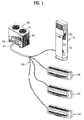
- FIG. 1 illustrates a perspective view of a multi-type air conditioner in accordance with a first preferred embodiment of the present invention, with partial cut away views;
- FIG. 2 illustrates a diagram of the multi-type air conditioner in accordance with a first preferred embodiment of the present invention during cooling operation, schematically;
- FIG. 3 illustrates key parts of an equalizing pipe arrangement between compressors in FIG. 2, schematically;
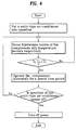
- FIG. 4 illustrates a flow chart showing the steps of a method for controlling a multi-type air conditioner in accordance with a first preferred embodiment of the present invention
- FIG. 5 illustrates a graph showing a critical temperature Tc of a compressor, and a correlation between a compressor internal temperature T and time, of a multi-type air conditioner of the present invention
- FIG. 6 illustrates a perspective view of a multi-type air conditioner in accordance with a second preferred embodiment of the present invention, with partial cut away views;
- FIG. 7 illustrates a diagram of the multi-type air conditioner in accordance with a second preferred embodiment of the present invention during cooling operation, schematically;
- FIG. 8 illustrates a flow chart showing the steps of a method for controlling a multi-type air conditioner in accordance with a second preferred embodiment of the present invention
- FIGS. 1 to 5 A multi-type air conditioner in accordance with a first preferred embodiment of the present invention will be described, with reference to FIGS. 1 to 5.
- the multi-type air conditioner includes one outdoor unit 80, a plurality of indoor units 51, 52, 53, and 54, and refrigerant pipelines 100 connected between the outdoor unit 80 and the indoor units 51, 52, 53, and 54.
- the plurality of indoor units 51, 52, 53, and 54 are connected in parallel to the outdoor unit 80 in parallel with the refrigerant pipelines 100. That is, refrigerant flow between the outdoor unit 80 and the indoor units 51, 52, 53, and 54 is made through the refrigerant pipelines 100.
- the indoor unit 51, 52, 53, or 54 includes an indoor fan 74 for drawing air from a room and discharging the air to the room again, and an indoor heat exchanger 72 for making the air drawn into the indoor unit 51, 52, 53, or 54 to heat exchange with refrigerant, to cool or heat the air.
- the outdoor unit 80 includes an outdoor fan 81 (see FIG. 1) for drawing outdoor air therein and discharging the outdoor air again, an outdoor heat exchanger 82 for making the air drawn by the outdoor fan 81 to heat exchange with refrigerant, a plurality of compressors 83, and 84 for compressing refrigerant, and a plurality of oil separators 85, and 86 connected to refrigerant discharge pipes 83a, and 84a of the compressors 83, and 84 for separating oil from refrigerant from the compressor 83, and 84, respectively.
- the compressor 83, or 84 includes a compression unit having a compression chamber for compressing refrigerant, a motor unit for compressing the compression chamber, and an oil pump for pumping oil for lubrication of the motor unit or the compression unit.
- the compressor discharges high temperature, and high pressure gaseous refrigerant, the oil is discharged together with the refrigerant, most of which is separated at the oil separator 85, or 86, and returns to a refrigerant suction pipe 83b, or 84b of the compressor 83, or 84, such that some of the oil circulates the refrigerating cycle together with refrigerant.
- the compressors 83, and 84 include a variable capacity compressor 83 having a variable capacity, and a single speed compressor 84 which is driven at a constant speed, so that, if a load on the indoor units 51, 52, 53, and 54 is low, for an example, in a case one or two of the plurality of indoor units 51, 52, 53, and 54 is in operation, only the variable capacity compressor 83 may be operated in correspondence to the load on the indoor unit 51, 52, 53, and 54, and, if the load on the indoor units 51, 52, 53, and 54 is relatively high, for an example, in a case three or four of the plurality of indoor units 51, 52, 53, and 54 are in operation, the single speed compressor 84 is operated together with the variable capacity compressor 83.
- An unexplained reference numeral 87a denotes a common accumulator in the outdoor unit 80 connected to the refrigerant suction pipes 83b and 84b of the variable capacity compressor 83 and the signal speed compressor 84, for accumulating liquid refrigerant so that only gaseous refrigerant is introduced into the variable capacity compressor 83 and the single speed compressor 84.
- An unexplained reference numeral 87b denotes a 4-way valve in the outdoor unit 80 for changing over a flow path such that refrigerant from the oil separator flows either to the indoor heat exchanger or the outdoor heat exchanger 82 so that the plurality of indoor units 51, 52, 53, and 54 can be used as coolers or heaters.
- An unexplained reference numeral 87c denotes a receiver in the outdoor unit 80 for storing surplus refrigerant, and making only liquid refrigerant to circulate toward an indoor unit side in cooling operation.
- An unexplained reference numeral 88a denotes an expansion device, such as an orifice or an electronic expansion valve, or so on, on the refrigerant pipeline 100 between the outdoor heat exchanger 82 and the indoor heat exchangers 72 for expanding refrigerant passed through the outdoor heat exchanger 82 or the indoor heat exchanger 72 to low temperature, and low pressure refrigerant.
- An unexplained reference numeral 88b denotes an electronic expansion valve on the outdoor unit for controlling a flow passage of the refrigerant for controlling a flow rate of the refrigerant circulating through the refrigerating cycle.
- An unexplained reference numeral 89 denotes a check valve on each of the refrigerant discharge pipes 83a, and 84a of the variable capacity compressor 83 and the single speed compressor 84 for preventing reverse flow of the refrigerant or the oil.
- the multi-type air conditioner further includes temperature sensors 163, and 164 in the compressors respectively, for sensing inside temperatures of the compressors 83, and 84 respectively, and an equalizing pipe 150 in communication with the compressors 83, and 84 for making uniform distribution of oil between the compressors 83, and 84 according to the temperatures sensed at the temperature sensors 163, and 164.
- the temperature sensors 163, and 164 are mounted adjacent to ends of the equalizing pipe 150, respectively. That is, it is preferable that the temperature sensors 163, and 164 are mounted at opposite ends of the equalizing pipe 150, respectively.
- the opposite ends of the equalizing pipe 150 are connected to position at a height at least higher than a lowest limit H0 of an oil level of the compressors 83, and 84. It is preferable that the opposite ends of the equalizing pipe 150 are positioned at a height higher than the lowest limit H0 of the oil level of the compressors 83, and 84. If there are three of more than three compressors in the outdoor unit, it is preferable that the equalizing pipe 150 is designed to be in communication with the compressors, to serve as a distribution pipe which prevents the oil from concentrating on one of the compressors, but makes the oil distributed among all the compressors. It is more preferable that a strainer 150a is further provided in the equalizing pipe 150 for separating foreign matters from flowing oil.
- the oil separated at the oil separators 85, and 86 returns to the compressors 83, and 84 through oil return pipes 156, and 157 connected between the oil separators 85, and 86, and the refrigerant suction pipes 83b, and 84b of the compressors 83, and 84, respectively.
- strainers 156a, and 157a are mounted on the oil return pipes 156, and 157 for separating foreign matters from the oil.
- a method for controlling the foregoing multi-type air conditioner in accordance with a first preferred embodiment of the present invention will be described.
- the multi-type air conditioner forms a cooling cycle such that the indoor units 51, 52, 53, and 54 cool rooms. If the refrigerant flow is changed over by means of the 4-way valve 87b such that the refrigerant flows in a reverse direction of the cooling, a heating cycle is formed such that the indoor units 51, 52, 53, and 54 heat rooms. Accordingly, in the following description, only a case will be described, in which the multi-type air conditioner forms the cooling cycle.
- the multi-type air conditioner If the multi-type air conditioner is operated such that some of the plurality of indoor units 51, 52, 53, and 54 are in cooling operation, for an example, one or two of the indoor units 51, 52, 53, and 54 is in cooling operation, the multi-type air conditioner operates the variable capacity compressor 83 only in the outdoor unit 80, leaving the single speed compressor 83 in the outdoor unit 80 stationary.
- variable capacity compressor 83 compresses the refrigerant to a high temperature, high pressure refrigerant and discharges to the refrigerant discharge pipe 83a together with the oil, and most of the oil is separated from the refrigerant as the discharged refrigerant and oil passes through the oil separator 85, and a portion of the oil circulates the refrigerating cycle together with the refrigerant.
- the refrigerant passed through the oil separator 85 passes through the 4-way valve 87b, the outdoor heat exchanger 82, the expansion device 88a in succession, and is introduced into the indoor heat exchanger of the indoor unit in cooling operation, vaporizes while cooling air around the indoor unit 72 such that the indoor unit serves as a cooler, and returns to the variable capacity compressor 83.
- the oil separated at the oil separator 85 returns to the refrigerant suction pipe 83b of the variable capacity compressor 83 through the oil return pipe 156, and, therefrom to the variable capacity compressor 83 together with the refrigerant returning to the variable capacity compressor 83.
- the multi-type air conditioner causes a non-uniform distribution of oil between the compressors 83, and 84 as oil in the refrigerating system concentrates on the variable capacity compressor 83 if operation of the variable capacity compressor 83 is continued for a long time period.
- the multi-type air conditioner of the present invention performs an operation in which the oil is distributed uniformly between the compressors 83, and 84 at an exact time point through the equalizing pipe 150 and the temperature sensors 163, and 164 at the opposite ends of the equalizing pipe 150, for preventing wear and noise from the compressors 83, and 84, extending lifetimes of the compressor 83, and 84, and improving a system efficiency.
- the temperature sensors 163, and 164 at the opposite ends of the equalizing pipe 150 sense temperatures inside of the compressors 83, and 84, respectively.
- the control unit compares the temperatures T3, and T4 of the compressors 83, and 84 sensed with the temperature sensors 163, and 164 to a preset critical temperature Tc of the compressors 83, and 84.
- the critical temperature Tc is an inside temperature of the compressor 83, or 84 when an amount of oil stored in the compressor 83, or 84 is a minimum amount the compressor 83, or 84 requires.
- the oil is transferred from the compressor 83 on which the oil is concentrated to the compressor 84 which has shortage of oil.
- the operation for equalizing oil between the compressors is performed, if the compressor at the critical time point is at least one.
- the multi-type air conditioner operates both the variable capacity compressor 83 and the single speed compressor 84 in correspondence to the load on the indoor units 51, 52, 53, and 54, if three or four of the indoor units 51, 52, 53, and 54 are operated.
- the multi-type air conditioner includes a plurality of outdoor units 80, and 90, a plurality of indoor units 51, 52, 53, 54, 61, 62, 63, and 64, and refrigerant pipelines 100 connected between the indoor units 51, 52, 53, 54, 61, 62, 63, and 64, and the outdoor units 80, and 90.
- the refrigerant pipelines 100 include a plurality of indoor unit connection pipes 101, 102, 103, 104, 111, 112, 113, and 114 respectively connected to the indoor units 51, 52, 53, 54, 61, 62, 63, and 64, a plurality of outdoor unit connection pipes 120, and 130 respectively connected to the outdoor units 80, and 90, and indoor/outdoor connection pipes 140 respectively connected between the indoor unit connection pipes 101, 102, 103, 104, 111, 112, 113, and 114 and the connection pipes 120, and 130, to connect the plurality of indoor units 51, 52, 53, 54, 61, 62, 63, and 64 to the plurality of outdoor units 80, and 90 in parallel.
- the refrigerant passed through the indoor units 51, 52, 53, 54, 61, 62, 63, and 64 joins at the indoor/outdoor connection pipes 140, and distributed to the outdoor units 80, and 90, and the refrigerant passed through the outdoor units 80, and 90 joins at the indoor/outdoor connection pipes 140, and distributed to the indoor units 51, 52, 53, 54, 61, 62, 63, and 64.
- each of the indoor units 51, 52, 53, 54, 61, 62, 63, and 64 has an indoor fan 72 for drawing air from a room and discharging the air to the room again, and an indoor heat exchanger 74 for making the air drawn into the indoor unit to heat exchange with the refrigerant, to cool or heat the room.
- the present invention is not limited to numbers of the outdoor units 80, and 90, and the indoor units 51, 52, 53, 54, 61, 62, 63, and 64, for convenience sake, the description of the multi-type air conditioner in accordance with a second preferred embodiment of the present invention will be proceeded with two outdoor units 80, and 90, and eight indoor units 51, 52, 53, 54, 61, 62, 63, and 64, taken as an example.
- the outdoor unit 80 includes an outdoor fan 81 (see FIG. 6) for drawing outdoor air therein and discharging the outdoor air again, an outdoor heat exchanger 82 for making the air drawn by the outdoor fan 81 to heat exchange with refrigerant, a plurality of compressors 83, and 84 for compressing refrigerant, and a plurality of oil separators 85, and 86 connected to refrigerant discharge pipes 83a, and 84a of the compressors 83, and 84 for separating oil from refrigerant from the compressor 83, and 84, respectively.
- the compressor 83, or 84 includes a compression unit having a compression chamber for compressing refrigerant, a motor unit for compressing the compression chamber, and an oil pump for pumping oil for lubrication of the motor unit or the compression unit.
- the compressor discharges high temperature, and high pressure gaseous refrigerant, the oil is discharged together with the refrigerant, most of which is separated at the oil separator 85, or 86, and returns to a refrigerant suction pipe 83b, or 84b of the compressor 83, or 84, such that some of the oil circulates the refrigerating cycle together with refrigerant.
- the compressors 83, and 84 include a variable capacity compressor 83 having a variable capacity, and a first single speed compressor 84 which is driven at a constant speed, so that, if a load on the indoor units 51, 52, 53, 54, 61, 62, 63, and 64 is low, for an example, in a case one or two of the plurality of indoor units 51, 52, 53, 54, 61, 62, 63, and 64 is in operation, only the variable capacity compressor 83 may be operated in correspondence to the load on the indoor unit 51, 52, 53, 54, 61, 62, 63, and 64, and, if the load on the indoor units 51, 52, 53, 54, 61, 62, 63, and 64 is relatively high, for an example, in a case three or four of the plurality of indoor units 51, 52, 53, 54, 61, 62, 63, and 64 are in operation, the first single speed compressor 84 is operated together with the variable capacity compressor 83.
- An unexplained reference numeral 87a denotes a common accumulator in the first outdoor unit 80 connected to the refrigerant suction pipes 83b and 84b of the variable capacity compressor 83 and the first signal speed compressor 84, for accumulating liquid refrigerant so that only gaseous refrigerant is introduced into the variable capacity compressor 83 and the first single speed compressor 84.
- An unexplained reference numeral 87b denotes a 4-way valve in the first outdoor unit 80 for changing over a flow path such that refrigerant from the oil separators 85, and 86 flows either to the indoor heat exchanger 74 or the outdoor heat exchanger 82 so that the plurality of indoor units 51, 52, 53, 54, 61, 62, 63, and 64 can be used as coolers or heaters.
- An unexplained reference numeral 87c denotes a receiver in the first outdoor unit 80 for storing surplus refrigerant, and making only liquid refrigerant to circulate toward an indoor unit side in cooling operation.
- An unexplained reference numeral 88a denotes an expansion device, such as an orifice or an electronic expansion valve, or so on, on the refrigerant pipeline 100 between the outdoor heat exchanger 82 and the indoor heat exchangers 72 for expanding refrigerant passed through the outdoor heat exchanger 82 or the indoor heat exchanger 72 to low temperature, and low pressure refrigerant.
- An unexplained reference numeral 88b denotes an electronic expansion valve on the first outdoor unit for controlling a flow passage of the refrigerant for controlling a flow rate of the refrigerant circulating through the refrigerating cycle.
- An unexplained reference numeral 89 denotes a check valve on each of the refrigerant discharge pipes 83a, and 84a of the variable capacity compressor 83 and the first single speed compressor 84 for preventing reverse flow of the refrigerant or the oil.
- the compressor of the second outdoor unit 90 includes second, and third single speed compressors 93, and 94, operated selectively depending on a load on the indoor units 51, 52, 53, 54, 61, 62, 63, and 64.
- the second single speed compressor 93 may be operated together with the variable capacity compressor 83, and the first single speed compressor 84, and if the load on the indoor units 51, 52, 53, 54, 61, 62, 63, and 64 is maximum, for an example, seven or eight of the indoor units 51, 52, 53, 54, 61, 62, 63, and 64 are in operation, the third single speed compressor 94 may be operated, together with the variable speed compressor 83, the first single speed compressor 84, and the second single speed compressor 93.
- the multi-type air conditioner further includes temperature sensors 163, 164, 173, and 174 in the compressors 83, 84, 93, and 94 respectively, for sensing inside temperatures of the compressors 83, 84, 93, and 94 respectively, and an equalizing pipe 150 in communication with the compressors 83, 84, 93, and 94 for making uniform distribution of oil among the compressors 83, 84, 93, and 94 according to the temperatures sensed at the temperature sensors 163, 164, 173, and 174.
- the equalizing pipe 150 is in communication with the variable capacity compressor 83, the first single speed compressor 84, the second single speed compressor, and the third single speed compressor, to prevent the oil from concentrating on one of the compressors 83, 84, 93, and 94, and to make the oil distributed among all the compressors 83, 84, 93, and 94.
- the equalizing pipe 150 includes a plurality of branch pipes 151, 152, 153, and 154, and a connection pipe 155 between the outdoor units 80, and 90 to make the branch pipes 151, and 152, and the branch pipes 153, and 154 in communication.
- Ends of the branch pipes 151, 152, 153, and 154 are connected to position at a height at least higher than a lowest limit of an oil level of the compressors 83, 84, 93, and 94. It is preferable that the ends of the branch pipes 151, 152, 153, and 154 are positioned at a height higher than the lowest limit of the oil level of the compressors 83, 84, 93, and 94. It is more preferable that strainers 151a, 152a, 153a, and 154a are further provided in the branch pipes 151, 152, 153, and 154 respectively, for separating foreign matters from flowing oil.
- the temperature sensors 163, 164, 173, and 174 are respectively mounted in the compressors 83, 84, 93, and 94 adjacent to the ends of the branch pipes 151, 152, 153, and 154 in communication with insides of the compressors 83, 84, 93, and 94.
- the oil separated at the oil separators 85, 86, 95, and 96 returns to the compressors 83, 84, 93, and 94 through oil return pipes 156, 157, 158, and 159 connected between the oil separators 85, 86, 95, and 96 and the refrigerant suction pipes 83b, 84b, 93b, and 94b of the compressors 83, 84, 93, and 94, respectively.
- strainers 156a, 157a, 158a, and 159a are mounted in the oil return pipes 156, 157, 158, and 159 for separating foreign matters from the oil.
- the multi-type air conditioner forms a cooling cycle such that the indoor units 51, 52, 53, 54, 61, 62, 63, and 64 cool rooms.
- the multi-type air conditioner If the multi-type air conditioner is operated such that some of the plurality of indoor units 51, 52, 53, 54, 61, 62, 63, and 64 are in cooling operation, for an example, one of the indoor units 51, 52, 53, 54, 61, 62, 63, and 64 is in cooling operation, the multi-type air conditioner operates the variable capacity compressor 83 only in the outdoor unit 80, leaving the first single speed compressor 83 in the first outdoor unit 80, the second, and third single speed compressors 93, and 94 in the second outdoor unit 90 stationary.
- variable capacity compressor 83 compresses the refrigerant to a high temperature, high pressure refrigerant and discharges to the refrigerant discharge pipe 83a together with the oil, and most of the oil is separated from the refrigerant as the discharged refrigerant and oil passes through the oil separator 85, and a portion of the oil circulates the refrigerating cycle together with the refrigerant.
- the refrigerant passed through the oil separator passes through the 4-way valve 87b, the outdoor heat exchanger 82, the expansion device 88a in succession, and is introduced into the indoor heat exchanger of the indoor unit in cooling operation, vaporizes while cooling air around the indoor unit 72 such that the indoor unit serves as a cooler, and returns to the variable capacity compressor 83.
- the oil separated from refrigerant at the oil separator 85 returns to the refrigerant suction pipe 83b of the variable capacity compressor 83 through the oil return pipe 156, and, therefrom to the variable capacity compressor 83 together with the refrigerant returning to the variable capacity compressor 83.
- the multi-type air conditioner causes a non-uniform distribution of oil among the compressors 83, 84, 94, and 95 as oil in the refrigerating system concentrates on the variable capacity compressor 83 if operation of the variable capacity compressor 83 is continued for a long time period.
- the multi-type air conditioner of in accordance with a second preferred embodiment of the present invention performs an operation in which the oil is distributed uniformly among the compressors 83, 84, 93, and 94 at an exact time point through the equalizing pipe 150 having the branch pipes 151, 152, 153, and 154, and the connection pipe 155, and the temperature sensors 163, 164, 173, and 174 at the ends of the branch pipes 151, 152, 153, and 154, for preventing wear and noise from the compressors 83, 84, 93, and 94, extending lifetimes of the compressor 83, 84, 93, and 94, and improving a system efficiency.
- the temperature sensors 163, 164, 173, and 174 at the ends of the branch pipes 151, 152, 153, and 154 sense temperatures inside of the compressors 83, 84, 93, and 94, respectively.
- the control unit compares the temperatures T13, T14, T23, and T24 of the compressors 83, 84, 93, and 94 sensed with the temperature sensors 163, 164, 173, and 174 to a preset critical temperature Tc of the compressors 83, 84, 93, and 94.
- the critical temperature Tc is an inside temperature of the compressor when an amount of oil stored in the compressor is a minimum amount the compressor requires.
- the oil is transferred from the compressor 83 on which the oil is concentrated to the compressors 84, 93, and 94 which have shortage of oil.
- the first, second, and third single speed compressors 84, 93, and 94 are operated in correspondence to the load on the indoor units 51, 52, 53, 54, 61, 62, 63, and 64.
- the performance of the operation for uniform distribution of oil among the compressors 83, 84, 93, and 94 at the exact time point at which the oil is distributed among the compressors 83, 84, 93, and 94 non-uniformly not only permits improvement of the performance of the compressors 83, 84, 93, and 94, but also permits improvement of system efficiency of the air conditioner having the compressors 83, 84, 93, and 94.
- the multi-type air conditioner of the present invention has the following advantages.
- the uniform distribution of oil among the compressors at an exact time point at which the oil is distributed among the compressors non-uniformly not only permits improvement of the performance of the compressors, but also permits improvement of system efficiency of the air conditioner having the compressors.
- the performance of the operation for uniform distribution of oil among the compressors only at a time point at which the oil is distributed among the compressors non-uniformly permits to minimize power consumption, to reduce an energy consumption effectively.
- the improvement of performance and efficiency of the multi-type air conditioner coming from improvement of the compressors permits to improve the cooling/heating performance of the multi-type air conditioner.
Landscapes
- Engineering & Computer Science (AREA)
- Physics & Mathematics (AREA)
- Mechanical Engineering (AREA)
- Thermal Sciences (AREA)
- General Engineering & Computer Science (AREA)
- Chemical & Material Sciences (AREA)
- Analytical Chemistry (AREA)
- Power Engineering (AREA)
- Compression-Type Refrigeration Machines With Reversible Cycles (AREA)
- Air Conditioning Control Device (AREA)
Abstract
Description
- This application claims the benefit of Korean Application No. P2004-93983, filed on November 17, 2004, which is hereby incorporated by reference as if fully set forth herein.
- The present invention relates to air conditioner, and more particularly, to a multi-type air conditioner and a method for controlling same, which can improve reliability of a compressor and system efficiency.
- In general, the air conditioner cools or/and heats rooms as the air conditioner performs steps of compression, condensing, expansion, and evaporation of refrigerant. In air conditioning systems, there are cooling air conditioner for supplying cold air to the room by operating a refrigerating cycle only in one direction, and cooling/heating air conditioner for supplying cold or warm air to the room by operating the refrigerating cycle in either direction, selectively.
- Moreover, there are general air conditioners in which one indoor unit is connected to one outdoor unit, and multi-type air conditioners in which a plurality of indoor units are connected to one outdoor unit. In the meantime, the multi-type air conditioner may have one of more than one outdoor unit.
- The multi-type air conditioner having one of more than one outdoor unit is provided with at least one compressor mounted on the outdoor unit. As the compressor, a single speed compressor of which operating frequency is constant, or a variable speed compressor of which operating frequency varies, is used.
- However, the multi-type air conditioner having an outdoor unit with a plurality of compressors mounted thereon has the following problems.
- That is, if the air conditioner is put into operation, there has been a problem of non-uniform distribution of oil among the plurality of compressors caused by differences of suction pressures of the compressors. Consequently, a compressor having a relative shortage of oil experiences drop of performance, to impair reliability. If the compressor is operated continuously in a state of oil shortage, the compressor is liable to burn. Moreover, the drop of performance of the compressor leads to drop an overall efficiency of the multi-type air conditioner, resulting to impair a cooling/heating performance.
- Accordingly, the present invention is directed to a multi-type air conditioner and a method for controlling same that substantially obviates one or more problems due to limitations and disadvantages of the related art.
- An object of the present invention is to provide a multi-type air conditioner and a method for controlling same, in which an oil distribution among compressor is made uniform at an exact time the oil is distributed non-uniformly among the compressors, for improving the compressor performance, to improve a performance of the air conditioner.
- Additional advantages, objects, and features of the invention will be set forth in part in the description which follows and in part will become apparent to those having ordinary skill in the art upon examination of the following or may be learned from practice of the invention. The objectives and other advantages of the invention may be realized and attained by the structure particularly pointed out in the written description and claims hereof as well as the appended drawings.
- To achieve these objects and other advantages and in accordance with the purpose of the invention, as embodied and broadly described herein, a multi-type air conditioner includes a plurality of compressors, a plurality of temperature sensors mounted in the plurality of compressors for sensing temperatures in the compressors, respectively, and an equalizing pipe in communication with the plurality of compressors, for uniform distribution of oil among the plurality of compressors according to the temperatures sensed at the plurality of temperature sensors respectively.
- Preferably, the temperature sensors are mounted adjacent to ends of the equalizing pipe, respectively.
- The ends of the equalizing pipe may be positioned at heights at least higher than a lowest oil level of the compressors, and the equalizing pipe may include branch pipes in communication with the plurality of compressors.
- The multi-type air conditioner may further include a strainer in the equalizing pipe for separating foreign matters from flowing oil.
- The plurality of compressors may include a variable capacity compressor of which capacity varies, and other one single speed compressor which is driven at a constant speed.
- The multi-type air conditioner may further include a plurality of oil separators in communication with the plurality of compressors for separating oil from refrigerant from the compressors respectively, and a plurality of oil return pipes respectively connected between the oil separators and compressors for guiding oil separated at the oil separators to the compressors. The oil return pipes may be respectively connected to refrigerant suction pipes of the compressors into which refrigerant is drawn.
- The multi-type air conditioner may further include strainers in the oil return pipes for separating foreign matters from flowing oil.
- In the meantime, in another aspect of the present invention, a multi-type air conditioner includes at least one outdoor unit having a plurality of compressors for compressing refrigerant, at least one indoor unit connected to the outdoor unit with refrigerant pipes, a plurality of temperature sensors mounted in the plurality of compressors for sensing temperatures in the compressors, respectively, and an equalizing pipe in communication with the plurality of compressors, for uniform distribution of oil among the plurality of compressors according to the temperatures sensed at the plurality of temperature sensors respectively.
- Preferably, the temperature sensors are mounted adjacent to the equalizing pipe in communication with insides of the compressors, respectively.
- The ends of the equalizing pipe are positioned at heights at least higher than a lowest oil level of the compressors, and, if the multi-type air conditioner has one outdoor unit, the equalizing pipe may include branch pipes in communication with the plurality of compressors, and, if the multi-type air conditioner has a plurality of outdoor units, the equalizing pipe may include branch pipes in communication with the plurality of compressors in respective outdoor units, and connection pipes for making the plurality of the outdoor units in communication between the branch pipes.
- The multi-type air conditioner may further include a strainer in the equalizing pipe for separating foreign matters from flowing oil.
- If the multi-type air conditioner has a plurality of outdoor units, one of the outdoor units includes the plurality of compressors having a variable capacity compressor of which capacity varies, and other one single speed compressor which is driven at a constant speed, and other one of the outdoor units includes the plurality of compressors having the single speed compressors.
- The multi-type air conditioner may further include a plurality of oil separators in communication with the plurality of compressors for separating oil from refrigerant from the compressors respectively, and a plurality of oil return pipes respectively connected between the oil separators and compressors for guiding oil separated at the oil separators to the compressors. The oil return pipes are respectively connected to refrigerant suction pipes of the compressors into which refrigerant are drawn.
- The multi-type air conditioner may further include strainers in the oil return pipes for separating foreign matters from flowing oil.
- Preferably, the refrigerant pipes connected between the outdoor unit and the indoor unit are parallel.
- In another aspect of the present invention, a method for controlling a multi-type air conditioner having at least one outdoor unit having a plurality of compressors for compressing refrigerant, at least one indoor unit connected to the outdoor unit with refrigerant pipes, a plurality of temperature sensors mounted in the plurality of compressors for sensing temperatures in the compressors respectively, and an equalizing pipe in communication with the plurality of compressors, for uniform distribution of oil among the plurality of compressors according to the temperatures sensed at the plurality of temperature sensors respectively, includes a sensing step of sensing temperatures of insides of the plurality of compressors with the plurality of temperature sensors respectively, a comparing step of comparing the temperatures of the insides of the compressors sensed thus to preset critical temperatures of the compressors respectively, and an operation step of distributing oil uniformly among the plurality of compressors according to a result of the comparison.
- The operation step is performed if there is at least one temperature below the critical temperature in the temperatures sensed with the temperature sensors, and the operation step includes the step of operating the plurality of compressors alternately for a preset time period.
- The critical temperature is a temperature inside of the compressor when an amount of oil stored in the compressor is a minimum amount the compressor requires.
- It is to be understood that both the foregoing general description and the following detailed description of the present invention are exemplary and explanatory and are intended to provide further explanation of the invention as claimed.
- The accompanying drawings, which are included to provide a further understanding of the invention and are incorporated in and constitute a part of this application, illustrate embodiment(s) of the invention and together with the description serve to explain the principle of the invention. In the drawings;
- FIG. 1 illustrates a perspective view of a multi-type air conditioner in accordance with a first preferred embodiment of the present invention, with partial cut away views;
- FIG. 2 illustrates a diagram of the multi-type air conditioner in accordance with a first preferred embodiment of the present invention during cooling operation, schematically;
- FIG. 3 illustrates key parts of an equalizing pipe arrangement between compressors in FIG. 2, schematically;
- FIG. 4 illustrates a flow chart showing the steps of a method for controlling a multi-type air conditioner in accordance with a first preferred embodiment of the present invention;
- FIG. 5 illustrates a graph showing a critical temperature Tc of a compressor, and a correlation between a compressor internal temperature T and time, of a multi-type air conditioner of the present invention;
- FIG. 6 illustrates a perspective view of a multi-type air conditioner in accordance with a second preferred embodiment of the present invention, with partial cut away views;
- FIG. 7 illustrates a diagram of the multi-type air conditioner in accordance with a second preferred embodiment of the present invention during cooling operation, schematically;
- FIG. 8 illustrates a flow chart showing the steps of a method for controlling a multi-type air conditioner in accordance with a second preferred embodiment of the present invention;
- Reference will now be made in detail to the preferred embodiments of the present invention, examples of which are illustrated in the accompanying drawings. Wherever possible, the same reference numbers will be used throughout the drawings to refer to the same or like parts.
- A multi-type air conditioner in accordance with a first preferred embodiment of the present invention will be described, with reference to FIGS. 1 to 5.
- Referring to FIG. 1, the multi-type air conditioner includes one
outdoor unit 80, a plurality ofindoor units refrigerant pipelines 100 connected between theoutdoor unit 80 and theindoor units - The plurality of
indoor units outdoor unit 80 in parallel with therefrigerant pipelines 100. That is, refrigerant flow between theoutdoor unit 80 and theindoor units refrigerant pipelines 100. - Referring to FIG. 2, the
indoor unit indoor fan 74 for drawing air from a room and discharging the air to the room again, and anindoor heat exchanger 72 for making the air drawn into theindoor unit - In the meantime, referring to FIG. 2, the
outdoor unit 80 includes an outdoor fan 81 (see FIG. 1) for drawing outdoor air therein and discharging the outdoor air again, anoutdoor heat exchanger 82 for making the air drawn by theoutdoor fan 81 to heat exchange with refrigerant, a plurality ofcompressors oil separators refrigerant discharge pipes compressors compressor - Though not shown, the
compressor oil separator refrigerant suction pipe compressor - It is preferable that the
compressors variable capacity compressor 83 having a variable capacity, and asingle speed compressor 84 which is driven at a constant speed, so that, if a load on theindoor units indoor units variable capacity compressor 83 may be operated in correspondence to the load on theindoor unit indoor units indoor units single speed compressor 84 is operated together with thevariable capacity compressor 83. - An unexplained reference numeral 87a denotes a common accumulator in the
outdoor unit 80 connected to therefrigerant suction pipes variable capacity compressor 83 and thesignal speed compressor 84, for accumulating liquid refrigerant so that only gaseous refrigerant is introduced into thevariable capacity compressor 83 and thesingle speed compressor 84. An unexplained reference numeral 87b denotes a 4-way valve in theoutdoor unit 80 for changing over a flow path such that refrigerant from the oil separator flows either to the indoor heat exchanger or theoutdoor heat exchanger 82 so that the plurality ofindoor units outdoor unit 80 for storing surplus refrigerant, and making only liquid refrigerant to circulate toward an indoor unit side in cooling operation. An unexplained reference numeral 88a denotes an expansion device, such as an orifice or an electronic expansion valve, or so on, on therefrigerant pipeline 100 between theoutdoor heat exchanger 82 and theindoor heat exchangers 72 for expanding refrigerant passed through theoutdoor heat exchanger 82 or theindoor heat exchanger 72 to low temperature, and low pressure refrigerant. An unexplained reference numeral 88b denotes an electronic expansion valve on the outdoor unit for controlling a flow passage of the refrigerant for controlling a flow rate of the refrigerant circulating through the refrigerating cycle. Anunexplained reference numeral 89 denotes a check valve on each of therefrigerant discharge pipes variable capacity compressor 83 and thesingle speed compressor 84 for preventing reverse flow of the refrigerant or the oil. - In the meantime, referring to FIG. 3, the multi-type air conditioner further includes
temperature sensors compressors pipe 150 in communication with thecompressors compressors temperature sensors - The
temperature sensors pipe 150, respectively. That is, it is preferable that thetemperature sensors pipe 150, respectively. - The opposite ends of the equalizing
pipe 150 are connected to position at a height at least higher than a lowest limit H0 of an oil level of thecompressors pipe 150 are positioned at a height higher than the lowest limit H0 of the oil level of thecompressors pipe 150 is designed to be in communication with the compressors, to serve as a distribution pipe which prevents the oil from concentrating on one of the compressors, but makes the oil distributed among all the compressors. It is more preferable that astrainer 150a is further provided in the equalizingpipe 150 for separating foreign matters from flowing oil. - In the meantime, the oil separated at the
oil separators compressors oil return pipes oil separators refrigerant suction pipes compressors - It is preferable that
strainers oil return pipes - A method for controlling the foregoing multi-type air conditioner in accordance with a first preferred embodiment of the present invention will be described. For reference, if refrigerant is made to circulate in a direction of the
outdoor heat exchanger 82, theexpansion device 88a, and theindoor heat exchanger 72 starting from thecompressors way valve 87b, the multi-type air conditioner forms a cooling cycle such that theindoor units way valve 87b such that the refrigerant flows in a reverse direction of the cooling, a heating cycle is formed such that theindoor units - If the multi-type air conditioner is operated such that some of the plurality of
indoor units indoor units variable capacity compressor 83 only in theoutdoor unit 80, leaving thesingle speed compressor 83 in theoutdoor unit 80 stationary. - Accordingly, the
variable capacity compressor 83 compresses the refrigerant to a high temperature, high pressure refrigerant and discharges to therefrigerant discharge pipe 83a together with the oil, and most of the oil is separated from the refrigerant as the discharged refrigerant and oil passes through theoil separator 85, and a portion of the oil circulates the refrigerating cycle together with the refrigerant. - That is, the refrigerant passed through the
oil separator 85 passes through the 4-way valve 87b, theoutdoor heat exchanger 82, theexpansion device 88a in succession, and is introduced into the indoor heat exchanger of the indoor unit in cooling operation, vaporizes while cooling air around theindoor unit 72 such that the indoor unit serves as a cooler, and returns to thevariable capacity compressor 83. - The oil separated at the
oil separator 85 returns to therefrigerant suction pipe 83b of thevariable capacity compressor 83 through theoil return pipe 156, and, therefrom to thevariable capacity compressor 83 together with the refrigerant returning to thevariable capacity compressor 83. - In the meantime, the multi-type air conditioner causes a non-uniform distribution of oil between the
compressors variable capacity compressor 83 if operation of thevariable capacity compressor 83 is continued for a long time period. - In this instance, the multi-type air conditioner of the present invention performs an operation in which the oil is distributed uniformly between the
compressors pipe 150 and thetemperature sensors pipe 150, for preventing wear and noise from thecompressors compressor - That is, referring to FIG. 4, upon putting the multi-type air conditioner in accordance with a first preferred embodiment of the present invention into operation, the
temperature sensors pipe 150 sense temperatures inside of thecompressors - Then, the control unit (not shown) compares the temperatures T3, and T4 of the
compressors temperature sensors compressors compressor compressor compressor - Accordingly, if one of the temperatures T3, and T4 of the
compressors compressors compressor - For an example, by operating the
compressors compressor 83 on which the oil is concentrated to thecompressor 84 which has shortage of oil. - Thus, by performing the operation for uniform distribution of oil between the
compressors compressors compressor compressors - For reference, a principle of a method for equalizing oil between the compressors of the present invention will be described, with reference to FIG. 5.
- During operation of the compressors, mixture of gaseous refrigerant, and oil is held in the compressor, and an amount of oil in the compressor which is relatively stationary is reduced gradually, leading to drop a concentration of oil in the compressor.
- Once the oil concentration drops, a pressure in the compressor drops, leading to drop the inside temperature of the compressor, too.
- Accordingly, by defining a temperature in the compressor in a case a minimum required quantity of oil is held in the compressor as a critical temperature Tc of the compressor, and a time point when the temperature T of the inside of the compressor is below the critical temperature Tc as a critical time point, the operation for equalizing oil between the compressors is performed, if the compressor at the critical time point is at least one.
- In the meantime, the multi-type air conditioner operates both the
variable capacity compressor 83 and thesingle speed compressor 84 in correspondence to the load on theindoor units indoor units - In this case, by the method for equalizing oil between the
compressors compressors compressors - Next, a multi-type air conditioner in accordance with a second preferred embodiment of the present invention will be described with reference to FIGS. 6 to 8.
- Referring to FIG. 6, the multi-type air conditioner includes a plurality of
outdoor units indoor units refrigerant pipelines 100 connected between theindoor units outdoor units - Referring to FIG. 7, the
refrigerant pipelines 100 include a plurality of indoorunit connection pipes indoor units unit connection pipes outdoor units outdoor connection pipes 140 respectively connected between the indoorunit connection pipes connection pipes indoor units outdoor units - The refrigerant passed through the
indoor units outdoor connection pipes 140, and distributed to theoutdoor units outdoor units outdoor connection pipes 140, and distributed to theindoor units - Moreover, each of the
indoor units indoor fan 72 for drawing air from a room and discharging the air to the room again, and anindoor heat exchanger 74 for making the air drawn into the indoor unit to heat exchange with the refrigerant, to cool or heat the room. - In the meantime, though the present invention is not limited to numbers of the
outdoor units indoor units outdoor units indoor units - Referring to FIG. 7, the
outdoor unit 80 includes an outdoor fan 81 (see FIG. 6) for drawing outdoor air therein and discharging the outdoor air again, anoutdoor heat exchanger 82 for making the air drawn by theoutdoor fan 81 to heat exchange with refrigerant, a plurality ofcompressors oil separators refrigerant discharge pipes compressors compressor - In the meantime, though not shown, the
compressor oil separator refrigerant suction pipe compressor - It is preferable that the
compressors variable capacity compressor 83 having a variable capacity, and a firstsingle speed compressor 84 which is driven at a constant speed, so that, if a load on theindoor units indoor units variable capacity compressor 83 may be operated in correspondence to the load on theindoor unit indoor units indoor units single speed compressor 84 is operated together with thevariable capacity compressor 83. - An unexplained reference numeral 87a denotes a common accumulator in the first
outdoor unit 80 connected to therefrigerant suction pipes variable capacity compressor 83 and the firstsignal speed compressor 84, for accumulating liquid refrigerant so that only gaseous refrigerant is introduced into thevariable capacity compressor 83 and the firstsingle speed compressor 84. An unexplained reference numeral 87b denotes a 4-way valve in the firstoutdoor unit 80 for changing over a flow path such that refrigerant from theoil separators indoor heat exchanger 74 or theoutdoor heat exchanger 82 so that the plurality ofindoor units outdoor unit 80 for storing surplus refrigerant, and making only liquid refrigerant to circulate toward an indoor unit side in cooling operation. An unexplained reference numeral 88a denotes an expansion device, such as an orifice or an electronic expansion valve, or so on, on therefrigerant pipeline 100 between theoutdoor heat exchanger 82 and theindoor heat exchangers 72 for expanding refrigerant passed through theoutdoor heat exchanger 82 or theindoor heat exchanger 72 to low temperature, and low pressure refrigerant. An unexplained reference numeral 88b denotes an electronic expansion valve on the first outdoor unit for controlling a flow passage of the refrigerant for controlling a flow rate of the refrigerant circulating through the refrigerating cycle. Anunexplained reference numeral 89 denotes a check valve on each of therefrigerant discharge pipes variable capacity compressor 83 and the firstsingle speed compressor 84 for preventing reverse flow of the refrigerant or the oil. - Referring to FIG. 7, system and operation of an outdoor fan 91 (see FIG. 6), indoor an
outdoor heat exchanger 92,oil separators common accumulator 97a, a 4-way valve 97b, areceiver 97c, an electronic expansion valve, and a check valve of the secondoutdoor unit 90 are the same with the firstoutdoor unit 80, except thecompressors - It is preferable that the compressor of the second
outdoor unit 90 includes second, and thirdsingle speed compressors indoor units - That is, if the load on the
indoor units indoor units single speed compressor 93 may be operated together with thevariable capacity compressor 83, and the firstsingle speed compressor 84, and if the load on theindoor units indoor units single speed compressor 94 may be operated, together with thevariable speed compressor 83, the firstsingle speed compressor 84, and the secondsingle speed compressor 93. - In the meantime, referring to FIG. 3, the multi-type air conditioner further includes
temperature sensors compressors compressors pipe 150 in communication with thecompressors compressors temperature sensors - The equalizing
pipe 150 is in communication with thevariable capacity compressor 83, the firstsingle speed compressor 84, the second single speed compressor, and the third single speed compressor, to prevent the oil from concentrating on one of thecompressors compressors pipe 150 includes a plurality ofbranch pipes connection pipe 155 between theoutdoor units branch pipes branch pipes branch pipes compressors branch pipes compressors strainers branch pipes - The
temperature sensors compressors branch pipes compressors - In the meantime, the oil separated at the
oil separators compressors oil return pipes oil separators refrigerant suction pipes compressors - It is preferable that
strainers oil return pipes - A method for controlling the foregoing multi-type air conditioner in accordance with a second preferred embodiment of the present invention will be described. For reference, if refrigerant is made to circulate in a direction of the
outdoor heat exchanger expansion device 88a, and theindoor heat exchanger 72 starting from thecompressors way valves indoor units way valves indoor units - If the multi-type air conditioner is operated such that some of the plurality of
indoor units indoor units variable capacity compressor 83 only in theoutdoor unit 80, leaving the firstsingle speed compressor 83 in the firstoutdoor unit 80, the second, and thirdsingle speed compressors outdoor unit 90 stationary. - The
variable capacity compressor 83 compresses the refrigerant to a high temperature, high pressure refrigerant and discharges to therefrigerant discharge pipe 83a together with the oil, and most of the oil is separated from the refrigerant as the discharged refrigerant and oil passes through theoil separator 85, and a portion of the oil circulates the refrigerating cycle together with the refrigerant. - That is, the refrigerant passed through the oil separator passes through the 4-
way valve 87b, theoutdoor heat exchanger 82, theexpansion device 88a in succession, and is introduced into the indoor heat exchanger of the indoor unit in cooling operation, vaporizes while cooling air around theindoor unit 72 such that the indoor unit serves as a cooler, and returns to thevariable capacity compressor 83. - The oil separated from refrigerant at the
oil separator 85 returns to therefrigerant suction pipe 83b of thevariable capacity compressor 83 through theoil return pipe 156, and, therefrom to thevariable capacity compressor 83 together with the refrigerant returning to thevariable capacity compressor 83. - In the meantime, the multi-type air conditioner causes a non-uniform distribution of oil among the
compressors variable capacity compressor 83 if operation of thevariable capacity compressor 83 is continued for a long time period. - In this instance, the multi-type air conditioner of in accordance with a second preferred embodiment of the present invention performs an operation in which the oil is distributed uniformly among the
compressors pipe 150 having thebranch pipes connection pipe 155, and thetemperature sensors branch pipes compressors compressor - That is, referring to FIG. 8, upon putting the multi-type air conditioner in accordance with a second preferred embodiment of the present invention into operation, the
temperature sensors branch pipes compressors - Then, the control unit (not shown) compares the temperatures T13, T14, T23, and T24 of the
compressors temperature sensors compressors - Accordingly, if one of the temperatures T13, T14, T23, and T24 of the
compressors compressors compressor - For an example, by operating the
compressors compressor 83 on which the oil is concentrated to thecompressors - Thus, by performing the operation for uniform distribution of oil among the
compressors compressors compressor compressors - In the meantime, if two, or more than two of the
indoor units single speed compressors indoor units - In this case too, the performance of the operation for uniform distribution of oil among the
compressors compressors compressors compressors - The multi-type air conditioner of the present invention has the following advantages.
- First, the uniform distribution of oil among the compressors at an exact time point at which the oil is distributed among the compressors non-uniformly, not only permits improvement of the performance of the compressors, but also permits improvement of system efficiency of the air conditioner having the compressors.
- Second, the performance of the operation for uniform distribution of oil among the compressors only at a time point at which the oil is distributed among the compressors non-uniformly permits to minimize power consumption, to reduce an energy consumption effectively.
- The improvement of performance and efficiency of the multi-type air conditioner coming from improvement of the compressors permits to improve the cooling/heating performance of the multi-type air conditioner.
- It will be apparent to those skilled in the art that various modifications and variations can be made in the present invention without departing from the spirit or scope of the inventions. Thus, it is intended that the present invention covers the modifications and variations of this invention provided they come within the scope of the appended claims and their equivalents.
Claims (13)
- A multi-type air conditioner comprising:a plurality of compressors;a plurality of temperature sensors mounted in the plurality of compressors for sensing temperatures in the compressors, respectively; andan equalizing pipe in communication with the plurality of compressors, for uniform distribution of oil among the plurality of compressors according to the temperatures sensed at the plurality of temperature sensors respectively.
- The multi-type air conditioner as claimed in claim 1, wherein the temperature sensors are mounted adjacent to ends of the equalizing pipe, respectively.
- The multi-type air conditioner as claimed in claim 1, wherein the ends of the equalizing pipe are positioned at heights at least higher than a lowest oil level of the compressors.
- The multi-type air conditioner as claimed in claim 1, wherein the equalizing pipe includes branch pipes in communication with the plurality of compressors.
- The multi-type air conditioner as claimed in claim 1, further comprising a strainer in the equalizing pipe for separating foreign matters from flowing oil.
- The multi-type air conditioner as claimed in claim 1, wherein the plurality of compressors include a variable capacity compressor of which capacity varies, and other one single speed compressor which is driven at a constant speed.
- The multi-type air conditioner as claimed in claim 1, further comprising:a plurality of oil separators in communication with the plurality of compressors for separating oil from refrigerant from the compressors respectively; anda plurality of oil return pipes respectively connected between the oil separators and compressors for guiding oil separated at the oil separators to the compressors.
- The multi-type air conditioner as claimed in claim 7, wherein the oil return pipes are respectively connected to refrigerant suction pipes of the compressors into which refrigerant is drawn.
- The multi-type air conditioner as claimed in claim 7, further comprising strainers in the oil return pipes for separating foreign matters from flowing oil.
- A method for controlling a multi-type air conditioner having at least one outdoor unit having a plurality of compressors for compressing refrigerant, at least one indoor unit connected to the outdoor unit with refrigerant pipes, a plurality of temperature sensors mounted in the plurality of compressors for sensing temperatures in the compressors respectively, and an equalizing pipe in communication with the plurality of compressors, for uniform distribution of oil among the plurality of compressors according to the temperatures sensed at the plurality of temperature sensors respectively, the method comprising:a sensing step of sensing temperatures of insides of the plurality of compressors with the plurality of temperature sensors respectively;a comparing step of comparing the temperatures of the insides of the compressors sensed thus to preset critical temperatures of the compressors, respectively; andan operation step of distributing oil uniformly among the plurality of compressors according to a result of the comparison.
- The method as claimed in claim 10, wherein the operation step is performed if there is at least one temperature below the critical temperature in the temperatures sensed with the temperature sensors.
- The method as claimed in claim 10, wherein the operation step includes the step of operating the plurality of compressors alternately for a preset time period.
- The method as claimed in claim 10, wherein the critical temperature is a temperature inside of the compressor when an amount of oil stored in the compressor is a minimum amount the compressor requires.
Applications Claiming Priority (1)
| Application Number | Priority Date | Filing Date | Title |
|---|---|---|---|
| KR1020040093983A KR100758901B1 (en) | 2004-11-17 | 2004-11-17 | Multi air conditioner |
Publications (1)
| Publication Number | Publication Date |
|---|---|
| EP1666813A1 true EP1666813A1 (en) | 2006-06-07 |
Family
ID=36000697
Family Applications (1)
| Application Number | Title | Priority Date | Filing Date |
|---|---|---|---|
| EP05024435A Withdrawn EP1666813A1 (en) | 2004-11-17 | 2005-11-09 | Multi-type air conditioner and method to distribute oil uniformly |
Country Status (4)
| Country | Link |
|---|---|
| US (1) | US7721559B2 (en) |
| EP (1) | EP1666813A1 (en) |
| KR (1) | KR100758901B1 (en) |
| CN (1) | CN100451498C (en) |
Cited By (2)
| Publication number | Priority date | Publication date | Assignee | Title |
|---|---|---|---|---|
| CN101093121B (en) * | 2006-06-21 | 2010-05-26 | 海尔集团公司 | A multi-connected air conditioner unit oil balance device |
| EP3078925A1 (en) * | 2015-04-07 | 2016-10-12 | Heatcraft Refrigeration Products LLC | Variable capacity condensing unit |
Families Citing this family (10)
| Publication number | Priority date | Publication date | Assignee | Title |
|---|---|---|---|---|
| KR100888964B1 (en) * | 2006-12-31 | 2009-03-17 | 엘지전자 주식회사 | Air Conditioning System and Its Control Method |
| US9541313B2 (en) * | 2009-03-31 | 2017-01-10 | Mitsubishi Electric Corporation | Refrigerating device |
| US8011191B2 (en) | 2009-09-30 | 2011-09-06 | Thermo Fisher Scientific (Asheville) Llc | Refrigeration system having a variable speed compressor |
| CN102753913B (en) * | 2010-02-15 | 2015-10-21 | 东芝开利株式会社 | Air conditioner |
| EP2369255B1 (en) * | 2010-03-15 | 2018-05-02 | LG Electronics Inc. | Air conditioning system and communication method thereof |
| KR101495186B1 (en) * | 2010-04-01 | 2015-02-24 | 엘지전자 주식회사 | Air conditioner with multiple compressors and an operation method thereof |
| KR101452767B1 (en) * | 2010-04-01 | 2014-10-21 | 엘지전자 주식회사 | Oil level detecting means for compressor |
| JP5885944B2 (en) * | 2011-06-17 | 2016-03-16 | 三菱重工業株式会社 | Multi-type air conditioner and control method of multi-type air conditioner |
| US10794621B2 (en) * | 2016-11-18 | 2020-10-06 | Lg Electronics Inc. | Air conditoner and method for controlling an air conditioner |
| US10969165B2 (en) | 2017-01-12 | 2021-04-06 | Emerson Climate Technologies, Inc. | Micro booster supermarket refrigeration architecture |
Citations (7)
| Publication number | Priority date | Publication date | Assignee | Title |
|---|---|---|---|---|
| JPH01203848A (en) * | 1988-02-10 | 1989-08-16 | Toshiba Corp | Air conditioner |
| JPH08128764A (en) * | 1994-10-31 | 1996-05-21 | Daikin Ind Ltd | Compressor oil temperature sensor mounting structure |
| JPH08200856A (en) * | 1995-01-31 | 1996-08-06 | Daikin Ind Ltd | Refrigeration system operation controller |
| JPH08200854A (en) * | 1995-01-31 | 1996-08-06 | Daikin Ind Ltd | Refrigerator |
| EP0838640A2 (en) * | 1996-10-28 | 1998-04-29 | Matsushita Refrigeration Company | Oil level equalizing system for plural compressors |
| US6125642A (en) * | 1999-07-13 | 2000-10-03 | Sporlan Valve Company | Oil level control system |
| US20030066302A1 (en) * | 2000-01-21 | 2003-04-10 | Kiyotaka Ueno | Oil amount detector, refrigeration apparatus and air conditioner |
Family Cites Families (7)
| Publication number | Priority date | Publication date | Assignee | Title |
|---|---|---|---|---|
| US3581519A (en) * | 1969-07-18 | 1971-06-01 | Emhart Corp | Oil equalization system |
| JPH01203677A (en) * | 1988-02-09 | 1989-08-16 | Toshiba Corp | Air conditioner |
| JPH03286198A (en) * | 1990-04-02 | 1991-12-17 | Daikin Ind Ltd | Oil level controller of oil separator in refrigerating device |
| CN1188218A (en) * | 1996-10-28 | 1998-07-22 | 松下冷机株式会社 | Oil level equalizing system for plural compressors |
| JP3042506B2 (en) * | 1998-07-27 | 2000-05-15 | ダイキン工業株式会社 | Refrigeration equipment |
| AU2109302A (en) * | 2000-12-08 | 2002-06-18 | Daikin Ind Ltd | Refrigerator |
| KR100694915B1 (en) | 2003-02-27 | 2007-03-14 | 도시바 캐리어 가부시키 가이샤 | Refrigeration cycle unit |
-
2004
- 2004-11-17 KR KR1020040093983A patent/KR100758901B1/en not_active Expired - Fee Related
-
2005
- 2005-11-09 EP EP05024435A patent/EP1666813A1/en not_active Withdrawn
- 2005-11-16 US US11/274,329 patent/US7721559B2/en not_active Expired - Fee Related
- 2005-11-17 CN CNB2005101250715A patent/CN100451498C/en not_active Expired - Fee Related
Patent Citations (7)
| Publication number | Priority date | Publication date | Assignee | Title |
|---|---|---|---|---|
| JPH01203848A (en) * | 1988-02-10 | 1989-08-16 | Toshiba Corp | Air conditioner |
| JPH08128764A (en) * | 1994-10-31 | 1996-05-21 | Daikin Ind Ltd | Compressor oil temperature sensor mounting structure |
| JPH08200856A (en) * | 1995-01-31 | 1996-08-06 | Daikin Ind Ltd | Refrigeration system operation controller |
| JPH08200854A (en) * | 1995-01-31 | 1996-08-06 | Daikin Ind Ltd | Refrigerator |
| EP0838640A2 (en) * | 1996-10-28 | 1998-04-29 | Matsushita Refrigeration Company | Oil level equalizing system for plural compressors |
| US6125642A (en) * | 1999-07-13 | 2000-10-03 | Sporlan Valve Company | Oil level control system |
| US20030066302A1 (en) * | 2000-01-21 | 2003-04-10 | Kiyotaka Ueno | Oil amount detector, refrigeration apparatus and air conditioner |
Non-Patent Citations (3)
| Title |
|---|
| PATENT ABSTRACTS OF JAPAN vol. 013, no. 506 (M - 892) 14 November 1989 (1989-11-14) * |
| PATENT ABSTRACTS OF JAPAN vol. 1996, no. 09 30 September 1996 (1996-09-30) * |
| PATENT ABSTRACTS OF JAPAN vol. 1996, no. 12 26 December 1996 (1996-12-26) * |
Cited By (2)
| Publication number | Priority date | Publication date | Assignee | Title |
|---|---|---|---|---|
| CN101093121B (en) * | 2006-06-21 | 2010-05-26 | 海尔集团公司 | A multi-connected air conditioner unit oil balance device |
| EP3078925A1 (en) * | 2015-04-07 | 2016-10-12 | Heatcraft Refrigeration Products LLC | Variable capacity condensing unit |
Also Published As
| Publication number | Publication date |
|---|---|
| CN1776330A (en) | 2006-05-24 |
| KR20060053575A (en) | 2006-05-22 |
| KR100758901B1 (en) | 2007-09-14 |
| US7721559B2 (en) | 2010-05-25 |
| CN100451498C (en) | 2009-01-14 |
| US20060117776A1 (en) | 2006-06-08 |
Similar Documents
| Publication | Publication Date | Title |
|---|---|---|
| JP4013261B2 (en) | Refrigeration equipment | |
| US6722156B2 (en) | Refrigeration system | |
| EP2428750B1 (en) | Refrigerator | |
| US9587867B2 (en) | Chiller system and control method thereof | |
| AU749518B2 (en) | Refrigerating device | |
| KR101387478B1 (en) | Compression system and Air-conditioning system using the same | |
| US8516847B2 (en) | Thermal storage air conditioner | |
| EP1659350A1 (en) | Compressor oil recovering apparatus and multi-unit air conditioner equipped with the same | |
| US6807817B2 (en) | Method for operating compressors of air conditioner | |
| EP1666813A1 (en) | Multi-type air conditioner and method to distribute oil uniformly | |
| KR100846567B1 (en) | Refrigerating apparatus | |
| EP3999791B1 (en) | Chiller system with multiple compressors | |
| US20100326125A1 (en) | Refrigeration system | |
| US20220082308A1 (en) | Refrigeration apparatus | |
| EP1643196B1 (en) | Air conditioner | |
| KR20080032870A (en) | Compressor oil recovery system and oil recovery method for multi air conditioner | |
| EP2908062B1 (en) | Outdoor Unit of Air Conditioner | |
| KR102104818B1 (en) | chiller | |
| KR101509575B1 (en) | Oil distribution device and air-conditioning apparatus comprising the same | |
| KR101418155B1 (en) | An air conditioner | |
| KR101203848B1 (en) | A compressor oil retrieving apparatus of multi-type air conditioner | |
| KR100710368B1 (en) | Multi air conditioner | |
| JP3480778B2 (en) | Multi-type air conditioner | |
| KR20050045252A (en) | Apparatus for controlling flow of refrigerants of multi type air-conditioner | |
| KR20110020335A (en) | Compressor oil distribution system |
Legal Events
| Date | Code | Title | Description |
|---|---|---|---|
| PUAI | Public reference made under article 153(3) epc to a published international application that has entered the european phase |
Free format text: ORIGINAL CODE: 0009012 |
|
| 17P | Request for examination filed |
Effective date: 20051109 |
|
| AK | Designated contracting states |
Kind code of ref document: A1 Designated state(s): AT BE BG CH CY CZ DE DK EE ES FI FR GB GR HU IE IS IT LI LT LU LV MC NL PL PT RO SE SI SK TR |
|
| AX | Request for extension of the european patent |
Extension state: AL BA HR MK YU |
|
| 17Q | First examination report despatched |
Effective date: 20061012 |
|
| AKX | Designation fees paid |
Designated state(s): DE FR GB IT |
|
| 17Q | First examination report despatched |
Effective date: 20061012 |
|
| STAA | Information on the status of an ep patent application or granted ep patent |
Free format text: STATUS: THE APPLICATION IS DEEMED TO BE WITHDRAWN |
|
| 18D | Application deemed to be withdrawn |
Effective date: 20070927 |